


This should take overall.

This 3D Model consists of files in StereoLithography (.Stl) format that is optimized for 3D printing.
Before printing the files, we strongly recommend reading the PRINTING DETAILS section.
WHAT WILL YOU GET AFTER PURCHASE?
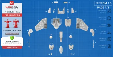
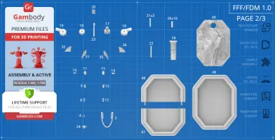
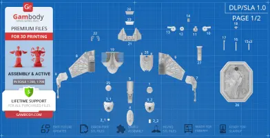
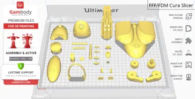
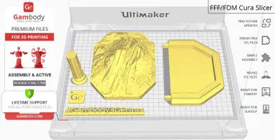
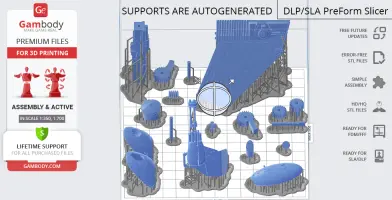
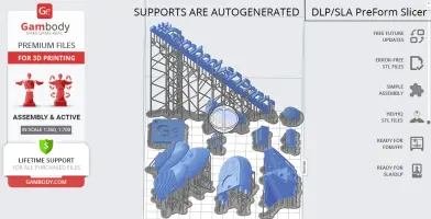
- 2 versions of Klingon Bird-of-Prey STL files for FFF/FDM and DLP/SLA/SLS - files for all versions are available for download after the purchase
- STL files of high-poly Bird-of-Prey ship 3D Model for 3D printing consist of 77 parts
- Sizes:
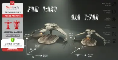
FFF/FDM: 152 mm tall, 416 mm wide, 312 mm deep
DLP/SLA/SLS: 76 mm tall, 208 mm wide, 156 mm deep
- Assembly Manual for FFF/FDM 1.0 and DLP/SLA/SLS 1.0 versions in PDF format
- Detailed settings that we provide as a recommendation for Cura, Simplify3D and Slic3r for the best print
- Full technical support from the Gambody Support Team
Detailed information about this 3D printing model is available in the DESCRIPTION section.

|
|||||
|---|---|---|---|---|---|
| File Name | File Size | Time / Filament | Object Size (x/y/z mm) |
||
|
_1_head_top_FDM (repaired ).stl |
26.64 MiB | 3 h 13 min 2 m | 36 x 83 x 19 | Download | |
|
_2_1_head_bot_FDM (repair ed).stl |
25.69 MiB | 3 h 49 min 2 m | 52 x 18 x 59 | Download | |
|
_2_2_head_bot_v2_FDM (rep aired).stl |
34.99 MiB | 3 h 15 min 2 m | 52 x 59 x 18 | Download | |
|
_3_head_hutch_FDM (repair ed).stl |
3.03 MiB | 1 h 54 min 1 m | 31 x 32 x 25 | Download | |
|
_4_head_pipe_1_FDM (repai red).stl |
0.99 MiB | 2 min <1 m | 9 x 9 x 3 | Download | |
|
_5_head_pipe_2_FDM (repai red).stl |
9.43 MiB | 1 h 19 min 1 m | 46 x 14 x 60 | Download | |
|
_6_1_head_window_FDM (rep aired).stl |
0.06 MiB | 3 min <1 m | 12 x 12 x 1 | Download | |
|
_6_2_head_window_v2_FDM ( repaired).stl |
2.10 MiB | 28 min <1 m | 12 x 12 x 28 | Download | |
|
_8_neck_part_1_R_FDM (rep aired).stl |
1.19 MiB | 7 min <1 m | 15 x 3 x 7 | Download | |
|
_9_neck_part_2_R_FDM (rep aired).stl |
0.05 MiB | 5 min <1 m | 6 x 12 x 6 | Download | |
|
_10_neck_part_3_R_FDM (re paired).stl |
0.05 MiB | 5 min <1 m | 13 x 6 x 5 | Download | |
|
_11_neck_part_4_R_FDM (re paired).stl |
0.32 MiB | 8 min <1 m | 14 x 8 x 9 | Download | |
|
_12_neck_part_1_L_FDM (re paired).stl |
1.19 MiB | 7 min <1 m | 15 x 3 x 7 | Download | |
|
_13_neck_part_2_L_FDM (re paired).stl |
0.05 MiB | 5 min <1 m | 6 x 12 x 6 | Download | |
|
_14_neck_part_3_L_FDM (re paired).stl |
0.05 MiB | 5 min <1 m | 13 x 6 x 5 | Download | |
|
_15_neck_part_4_L_FDM (re paired).stl |
0.32 MiB | 8 min <1 m | 14 x 8 x 9 | Download | |
|
_16_gear_1_FDM (repaired) .stl |
0.32 MiB | 53 min <1 m | 42 x 32 x 10 | Download | |
|
_17_gear_2_FDM (repaired) .stl |
3.97 MiB | 50 min <1 m | 22 x 22 x 25 | Download | |
|
_18_gear_3_FDM (repaired) .stl |
0.54 MiB | 29 min <1 m | 22 x 22 x 10 | Download | |
|
_19_gear_4_FDM (repaired) .stl |
0.31 MiB | 53 min <1 m | 42 x 32 x 10 | Download | |
|
_20_gear_5_FDM (repaired) .stl |
11.77 MiB | 24 min <1 m | 13 x 13 x 15 | Download | |
|
_21_gear_beam_a_x3_FDM (r epaired).stl |
0.08 MiB | 8 min <1 m | 33 x 5 x 5 | Download | |
|
_22_gear_beam_b_FDM (repa ired).stl |
0.08 MiB | 11 min <1 m | 45 x 5 x 5 | Download | |
|
_23_gear_beam_c_FDM (repa ired).stl |
0.10 MiB | 14 min <1 m | 8 x 51 x 6 | Download | |
|
_24_gear_key_FDM (repaire d).stl |
0.32 MiB | 14 min <1 m | 18 x 7 x 12 | Download | |
|
_25_body_top_FDM (repaire d).stl |
81.13 MiB | 25 h 40 min 15 m | 115 x 114 x 37 | Download | |
|
_28_body_back_window_1_FD M (repaired).stl |
1.67 MiB | 1 h 19 min 1 m | 47 x 17 x 18 | Download | |
|
_26_body_bot_FDM (repaire d).stl |
27.36 MiB | 11 h 26 min 6 m | 68 x 26 x 87 | Download | |
|
_27_body_back_FDM (repair ed).stl |
4.09 MiB | 13 h 36 min 7 m | 73 x 54 x 69 | Download | |
|
_29_body_back_window_2_FD M (repaired).stl |
0.81 MiB | 1 h 11 min 1 m | 46 x 11 x 17 | Download | |
|
_30_body_beams_x10_FDM (r epaired).stl |
0.01 MiB | 7 min <1 m | 5 x 23 x 5 | Download | |
|
_31_body_panel_1_R_FDM (r epaired).stl |
1.20 MiB | 12 min <1 m | 19 x 36 x 4 | Download | |
|
_32_body_panel_2_R_FDM (r epaired).stl |
1.56 MiB | 11 min <1 m | 27 x 21 x 6 | Download | |
|
_33_body_panel_3_R_FDM (r epaired).stl |
0.32 MiB | 17 min <1 m | 12 x 26 x 8 | Download | |
|
_34_body_panel_wing_R_FDM (repaired).stl |
0.22 MiB | 1 h 6 min 1 m | 60 x 16 x 30 | Download | |
|
_35_body_panel_1_L_FDM (r epaired).stl |
1.20 MiB | 13 min <1 m | 19 x 36 x 4 | Download | |
|
_36_body_panel_2_L_FDM (r epaired).stl |
1.56 MiB | 11 min <1 m | 27 x 21 x 6 | Download | |
|
_37_body_panel_3_L_FDM (r epaired).stl |
0.32 MiB | 17 min <1 m | 12 x 26 x 8 | Download | |
|
_38_body_panel_wing_L_FDM (repaired).stl |
0.22 MiB | 1 h 6 min 1 m | 60 x 16 x 30 | Download | |
|
_39_body_panel_cap_FDM (r epaired).stl |
1.02 MiB | 33 min <1 m | 30 x 31 x 8 | Download | |
|
_40_wing_1_R_FDM (repaire d).stl |
7.23 MiB | 26 h 12 m | 137 x 62 x 138 | Download | |
|
_41_wing_2_R_FDM (repaire d).stl |
4.21 MiB | 5 h 29 min 3 m | 50 x 74 x 72 | Download | |
|
_42_wing_gun_R_FDM (repai red).stl |
4.27 MiB | 1 h 34 min 1 m | 10 x 14 x 86 | Download | |
|
_43_wing_1_L_FDM (repaire d).stl |
7.13 MiB | 26 h 1 min 12 m | 137 x 62 x 138 | Download | |
|
_44_wing_2_L_FDM (repaire d).stl |
4.21 MiB | 5 h 16 min 3 m | 50 x 74 x 72 | Download | |
|
_45_wing_gun_L_FDM (repai red).stl |
4.28 MiB | 1 h 33 min 1 m | 10 x 14 x 86 | Download | |
|
_46_platform_base_full_FD M (repaired).stl |
1.59 MiB | 21 h 24 min 12 m | 170 x 211 x 15 | Download | |
|
_47_platform_base_cut_1_F DM (repaired).stl |
0.83 MiB | 10 h 58 min 6 m | 170 x 105 x 15 | Download | |
|
_48_platform_base_cut_2_F DM (repaired).stl |
0.84 MiB | 10 h 55 min 6 m | 170 x 118 x 15 | Download | |
|
_49_platform_mount_FDM (r epaired).stl |
2.82 MiB | 31 h 27 min 17 m | 129 x 178 x 58 | Download | |
|
_50_platform_ladder_FDM ( repaired).stl |
6.16 MiB | 3 h 28 min 2 m | 33 x 30 x 74 | Download | |
|
Keychain (repaired).stl |
0.35 MiB | 23 min <1 m | 30 x 30 x 2 | Download | |
|
Tag (repaired).stl |
1.70 MiB | 1 h 18 min 1 m | 150 x 18 x 5 | Download | |
|
_7_neck_FDM (repaired).st l |
7.83 MiB | 8 h 35 min 4 m | 34 x 30 x 114 | Download | |
|
_26_body_bot_FDM_v2_for_l anding_gear (repaired).st l |
24.68 MiB | 10 h 16 min 6 m | 68 x 87 x 25 | Download | |
|
_50_platform_ladder_FDM_v 2 (repaired).stl |
8.99 MiB | 5 h 50 min 3 m | 47 x 50 x 104 | Download | |
|
_51_new_chassis_1_FDM (re paired).stl |
9.07 MiB | 2 h 25 min 1 m | 72 x 46 x 10 | Download | |
|
_52_new_chassis_2_FDM (re paired).stl |
0.58 MiB | 42 min <1 m | 11 x 26 x 50 | Download | |
|
_53_new_chassis_3_FDM (re paired).stl |
0.84 MiB | 1 h 42 min 1 m | 27 x 79 x 28 | Download | |
|
_54_new_chassis_4_FDM (re paired).stl |
0.84 MiB | 1 h 41 min 1 m | 27 x 79 x 28 | Download | |
| ... | |||||
This should take overall.
ABOUT THIS 3D MODEL
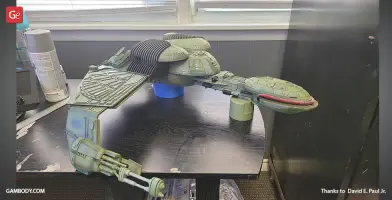
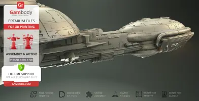
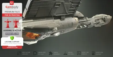
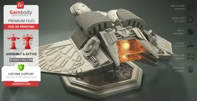
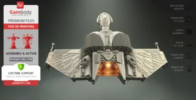
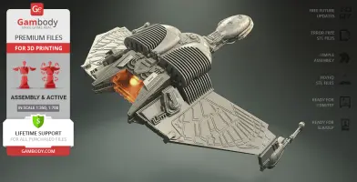
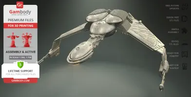
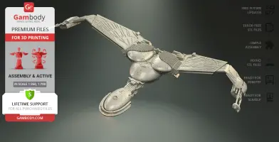
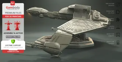
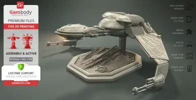
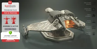
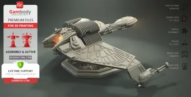
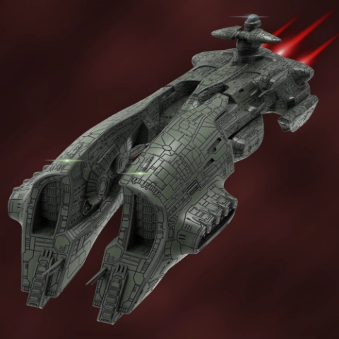
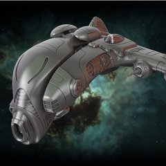
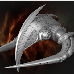
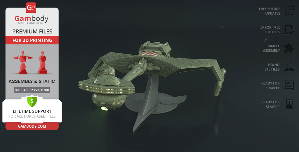
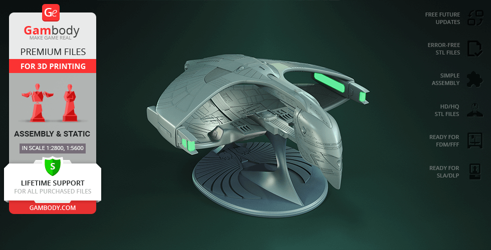
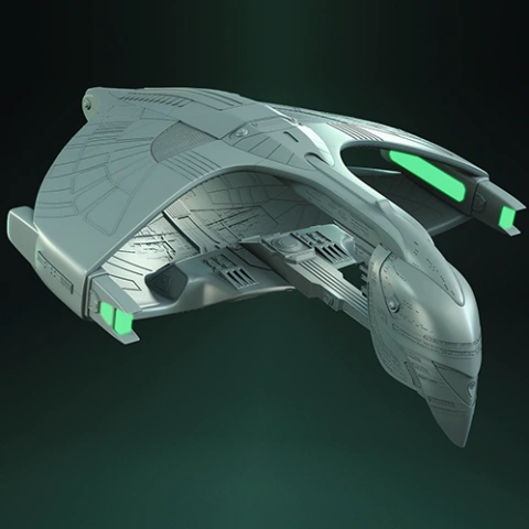
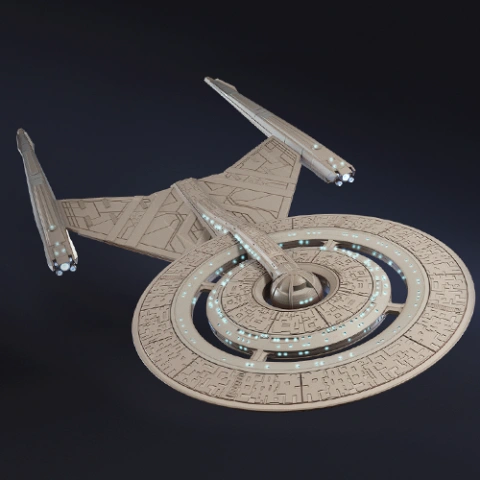
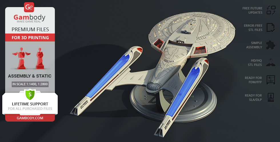
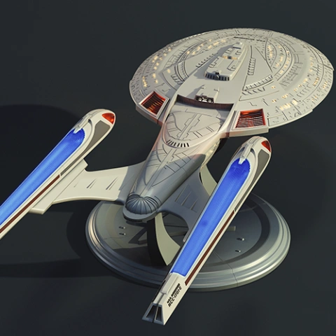
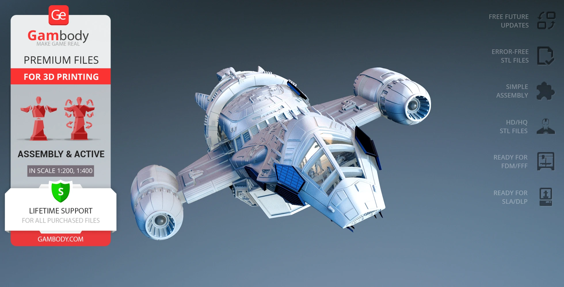
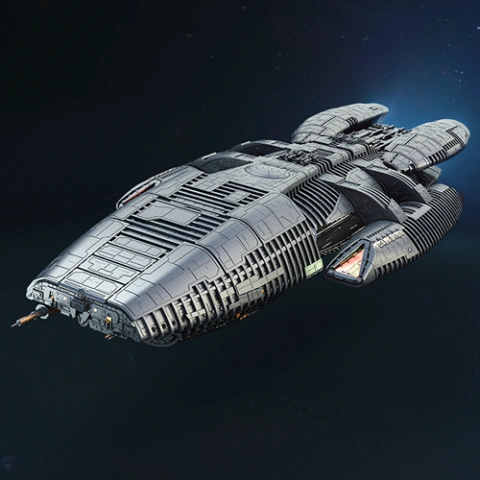
The gem of the Klingon Defense Forces and the Star Trek franchise, the Bird-of-Prey warship is as majestic as it is highly functional. Thanks to its great agility and the cutting-edge set of weapons, it was able to out-live various contemporaries and earn the status of a fearsome front-liner. Naturally, as an adventurist at heart willing to rival the merciless Klingons and a modeller deeply inspired by their advanced craft, our contributing 3D artist decided to recreate the Bird-of-Prey in the form of a model that can be simply 3D printed and added to your out-of-this-world diorama!
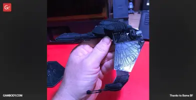
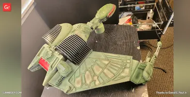
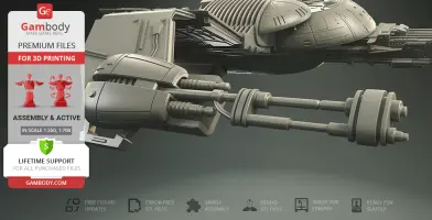
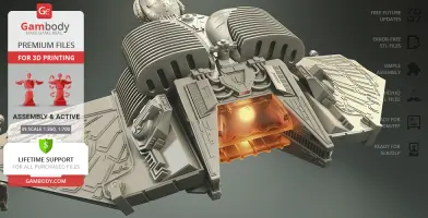
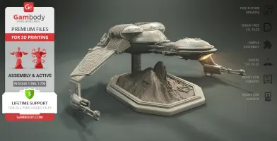
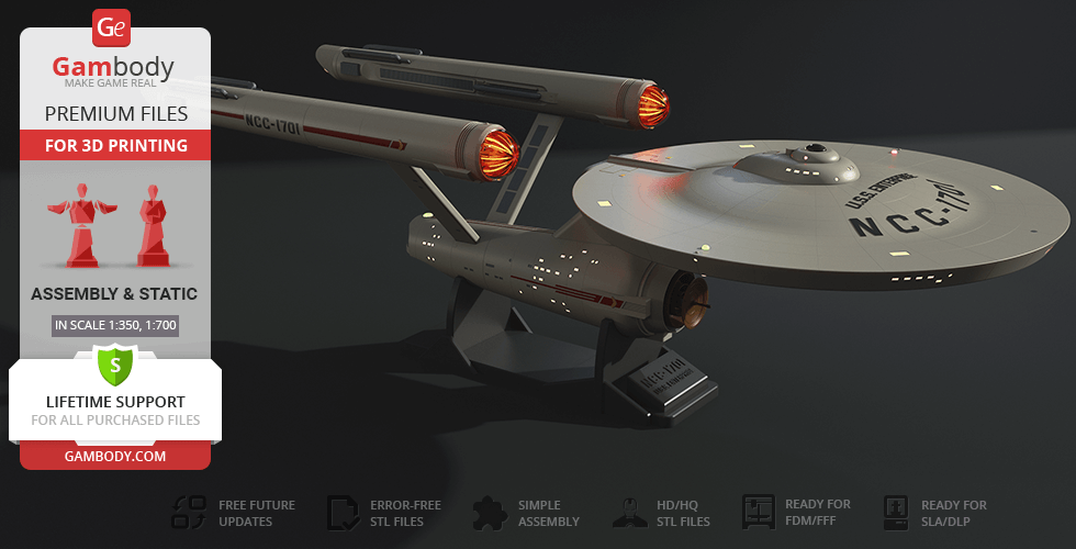
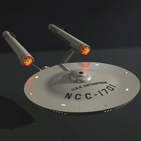
As opposed to the pristine and futuristic USS Enterprise, the Klingon Bird-of-Prey for 3D printing appears ominous and clunky. Its avian design and highly detailed feather-like hull plating emphasise the prestige and prowess of the ship. The craft has its trademark forward-firing wing-mounted disruptor cannons and the photon torpedo launcher on standby, waiting for commands of a tenacious captain. And for you to showcase the Klingon Bird-of-Prey as an invaluable trophy, the 3D printing model is provided with an elaborate platform resembling the landscape of a distant planet with the Star Trek insignia engraved on it.
ADAPTATION FOR 3D PRINTING
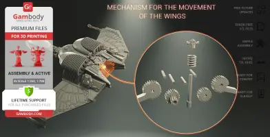
Klingon Bird-of-Prey for 3D printing is an active assembly model and its moderation and adaptation for different types of 3D printers took Gambody team 40 hours in total. For you to receive the cleanest 3D printing result possible and to minimize the amount of filament needed for generated support, the famous ship was divided into many assembly parts that are provided as separate STL files. For you to impress the spectators with your 3D printed piece, the special articulation mechanism was designed to fit inside the ship and set the Bird-of-Prey's wings into motion. Moreover, special tunnels throughout the ship were introduced for LED wiring and further enhancement of your display.
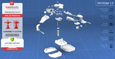
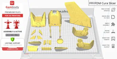
All assembly parts are provided in STL files of FFF/FDM version in recommended positions that were worked out in order to ensure the smoothness of the details’ surfaces after printing and that the 3D printing beginners won’t face difficulties when placing the parts on a build plate. When downloading any model’s file you will also receive “Assembly Manual” for FFF/FDM 1.0 and DLP/SLA/SLS 1.0 versions in PDF format. We highly recommend that you get acquainted with the “Assembly video” and “Assembly Manual” before getting down to the Klingon Bird-of-Prey model.
The model is saved in STL files, a format supported by most 3D printers. All STL files for 3D printing have been checked in Netfabb and no errors were shown.
The model’s scale was calculated from the length of the Klingon Bird-of-Prey which is 109000 mm. The 3D printing model’s chosen scale is 1:350 for the FFF/FDM version and 1:700 for the DLP/SLA/SLS version.
VERSIONS' SPECIFICATIONS
FFF/FDM 1.0 version features:
- Contains 50 parts;
- A printed model is 152 mm tall, 416 mm wide, 312 mm deep;
- There is a mechanism inside the ship that allows simultaneous movement of the wings up and down;
- The assembly kit includes a special key that ensures the simultaneous movement of the wings;
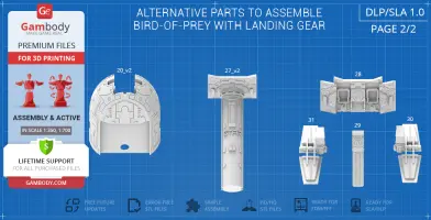
- There are two variants of the bottom part of the “head” and the photon torpedo launcher for you to choose from;
- You can display the model on a decorative platform or conceal the slot with a cap resembling a hatch + there is an optional landing gear;
- All parts are divided in such a way that you will print them with the smallest number of support structures.
DLP/SLA/SLS 1.0 version features:
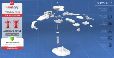
- Contains 27 parts;
- A printed model is 76 mm tall, 208 mm wide, 156 mm deep;
- There is a mechanism inside the ship that allows simultaneous movement of the wings up and down;
- The assembly kit includes a special key that ensures the simultaneous movement of the wings;
- There are two variants of the bottom part of the “head” and the photon torpedo launcher for you to choose from;
- You can display the model on a decorative platform or conceal the slot with a cap resembling a hatch + there is an optional landing gear;
- All parts are divided in such a way to fit the build plates and to ensure that support structures are generated where needed.
You can get the model of Klingon Bird-of-Prey for 3D Printing immediately after the purchase! Just click the green Buy button in the top-right corner of the model’s page. You can pay with PayPal or your credit card.
Watch the tutorial on how to assemble Klingon Bird-of-Prey 3D Printing Model at Gambody YouTube channel.
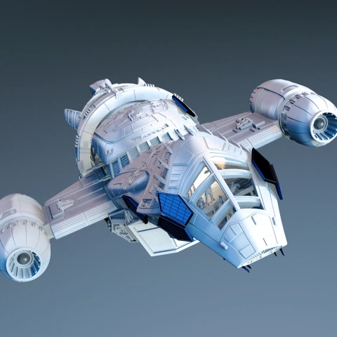
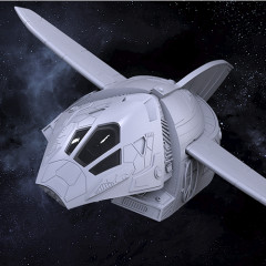
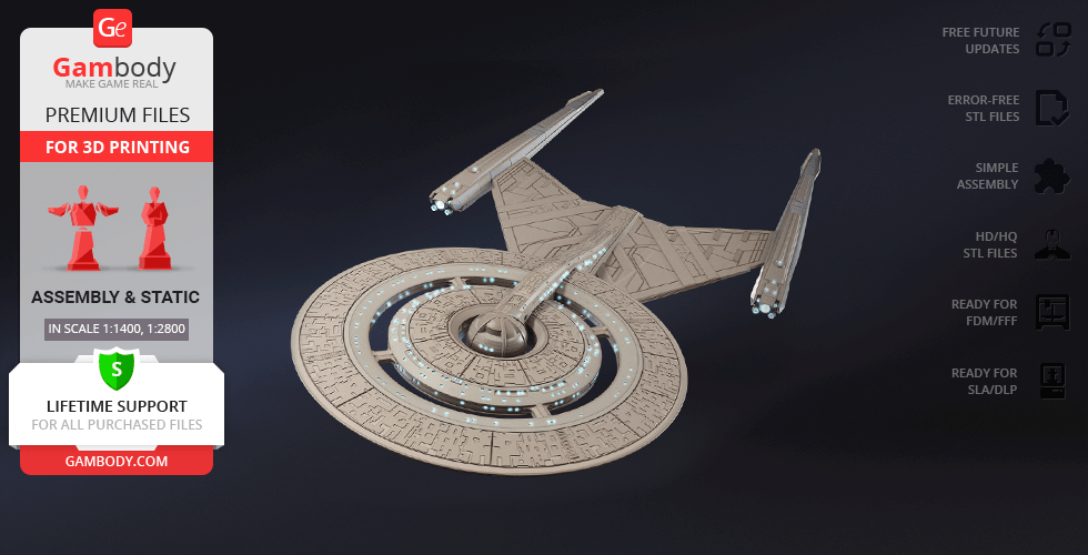
Also, you may like USS Enterprise NCC-1701 3D Printing Model and Spock 3D Printing Figurine, as well as other Space Ships 3D Printing Models.
_______
FAQ:
Where can I print a model if I have no printer?
How to get started with 3D printing?
How to set up my 3D printer?
How to choose right 3D model print bed positioning?
How to paint printed figurine?
Below you can find printing recommendations for Cura, Simplify3D and Slic3r software.
These are basic settings that were tested in Cura 4.8.0 slicer.
The test models were printed on Ultimaker 2, Creality Ender 3, Creality CR-10S Pro V2, Anycubic I3 Mega, Anycubic I3 MegaS 3D printers with PLA and PETG filaments.
Disclaimer: The following printing settings are a recommendation, not an obligation. The parameters can vary depending on the peculiarities of your 3D printer, the material you use and especially the particular assembly part at hand. Each part that any model comprises often needs preliminary review and you are free to tweak the settings the way you find suitable.
Note:
- You can scale up the model (downscaling is not recommended!);
- All connectors should be printed at 100% Infill;
- For all parts of locks (“ge_lock” in “Source files”) you need to change "Brim" type to "Skirt" in Build Plate Adhesion section.
Quality
Layer Height: 0.12 mm (you can also set Layer Height at 0.16 or 0.2mm for 0.4mm nozzles)
Initial Layer Height: 0.2 mm (carefully level the print bed and keep your Initial Layer Height the same as the main Layer Height)
Line Width: 0.4 mm
Wall Line Width: 0.4 mm
Outer Wall Line Width: 0.4 mm
Inner Wall(s) Line Width: 0.4 mm
Top/Bottom Line Width: 0.4 mm
Infill Line Width: 0.4 mm
Skirt/Brim Line Width: 0.4 mm
Support Line Width: 0.4 mm
Initial Layer Line Width: 100%
Shell
Wall Thickness: 0.8 mm
Wall Line Count: 2
Outer Wall Wipe Distance: 0.3 mm
Top Surface Skin Layers: 0
Top/Bottom Thickness: 0.6 mm
Top Thickness: 0.6 mm
Top Layers: 5
Bottom Thickness: 0.6 mm
Bottom Layers: 5
Initial Bottom Layers: 5
Top/Bottom Pattern: Lines
Bottom Pattern Initial Layer: Lines
Top/Bottom Line Directions: [ ]
Outer Wall Inset: 0 mm
Optimize Wall Printing Order: Check
Compensate Wall Overlaps: Check
Compensate Inner Wall Overlaps: Check
Minimum Wall Flow: 0%
Fill Gaps Between Walls: Everywhere
Filter Out Tiny Gaps: Check
Horizontal Expansion: 0 mm
Initial Layer Horizontal Expansion: 0 mm
Hole horizontal expansion: 0
Z Seam Alignment: User Specified
Z Seam Position: Back
Z Seam X: Average length of your printer’s plate (e.g.”150” if your plate is 300mm on the X-axis)
Z Seam Y: A value higher than the length of your plate on the Y-axis (e.g. 700)
Seam Corner Preference: Hide Seam
Extra Skin Wall Count: 1
Skin Overlap Percentage: 10%
Skin Overlap 0.04 mm
Infill
Infill Density: 20% (for all smaller parts and for all parts of connectors use 100% Infill)
Infill Pattern: Triangles
Connect Infill Lines: Check
Infill Line Directions: [ ]
Infill X Offset: 0 mm
Infill Y Offset: 0 mm
Infill Line Multiplier: 1
Extra Infill Wall Count: 0
Infill Overlap Percentage: 10-20%
Infill Overlap: 0.04 mm
Skin Overlap Percentage: 5%
Skin Overlap: 0.02 mm
Infill Wipe Distance: 0 mm
Infill Layer Thickness: 0.24 mm
Gradual Infill Steps: 0
Infill Before Walls: Check
Minimum Infill Area: 0 mm2
Skin Removal Width: 0.8 mm
Top Skin Removal Width: 0.8 mm
Bottom Skin Removal Width: 0.8 mm
Skin Expand Distance: 0.8
Top Skin Expand Distance: 0.8
Bottom Skin Expand Distance: 0.8
Maximum Skin Angle for Expansion: 90˚
Minimum Skin Width for Expansion: 0.0
Skin Edge Support Thickness: 0
Skin Edge Support Layers: 0
Material
Initial Layer Flow: 100%
Printing Temperature: See your filament settings
Initial Printing Temperature: Your filament settings
Final Printing Temperature: Your filament settings
Build Plate Temperature: Your filament settings
Build Plate Temperature Initial Layer: Your filament settings + 5°
Flow: 100% (Important! If you face difficulty printing the model, you may need to adjust the Flow parameter. You may research the topic using the Internet or seek assistance at our Customer Support Team at support@gambody.com)
Speed
You can increase the printing Speed by 20% when you print simple objects. For small/thin parts you need to decrease the Speed by 25% - 50%.
Print Speed: 50 mm/s
Infill Speed: 50 mm/s
Wall Speed: 25 mm/s
Outer Wall Speed:25 mm/s
Inner Wall Speed: 50 mm/s
Top/Bottom Speed: 25mm/s
Support Speed: 25 mm/s
Support Infill Speed: 45 mm/s
Support Interface Speed: 25 mm/s
Support Roof Speed: 25 mm/s
Support Floor Speed: 25 mm/s
Travel Speed: 80 mm/s
Initial Layer Speed: 80 mm/s
Initial Layer Print Speed: 20 mm/s
Initial Layer Travel Speed: 80 mm/s
Skirt/Brim Speed: 20 mm/s
Z Hop Speed: 5 mm/s
Number of Slower Layers: 2
Enable Acceleration Control: Check
When printing simple objects, you need to set all Acceleration parameters at 500 mm/s. For small/thin parts you need to decrease the Acceleration by 50% - 70%.
Travel
Enable Retraction: Check
Retraction Distance: 4-8 mm, 1-3 mm for Direct Extruder (This is the most important retraction parameter. You can find your optimal value of Retraction Distance by printing any test object, e.g. bridges, towers etc.)
Retraction Speed: 25mm/s
Retraction Retract Speed: 25 mm/s
Retraction Prime Speed: 25 mm/s
Retraction Extra Prime Amount: 0 mm3
Retraction Minimum Travel: 1.5 mm
Maximum Retraction Count: 100
Minimum Extrusion Distance Window: 6,5 - 10 mm
Limit Support Retractions: Check
Combing Mode: All
Max Comb Distance With No Retract: 30 mm
Retract Before Outer Wall: Check
Avoid Printed Parts When Travelling: Check
Avoid Supports When Travelling: Check
Travel Avoid Distance: 1 mm
Layer Start X: 0.0 mm
Layer Start Y: 0.0 mm
Z Hop When Retracted: Check
Z Hop Height: 0,3 mm
Cooling
Enable Print Cooling: Check
Fan Speed: 100%
Regular Fan Speed: 100%
Maximum Fan Speed: 100%
Regular/Maximum Fan Speed Threshold: 10 s
Initial Fan Speed: 0%
Regular Fan Speed at Height: 0.36 mm
Regular Fan Speed at Layer: 3
Minimum Layer Time: 10 s
Minimum Speed: 10 mm/s
Support
Generate Support: Check
Support Structure: Normal (you can try using Tree Support Structure if you have difficulty printing any particular assembly part)
Support Placement: Everywhere
Support Overhang Angle: 60° (this parameter can range from 30° to 70° depending on the part at hand)
Support Pattern: Zig Zag
Support Wall Line Count: 1 (stronger support that might be more difficult to remove) 0 (less strong support but is easier to remove)
Support Density: 15%
Support Line Distance: 2.6667 mm
Initial layer support line distance: 2.667 mm
Support Z Distance: 0.12 mm
Support Top Distance: 0.12 mm
Support Bottom Distance: 0.12 mm
Support X/Y Distance: 0.8-1 mm
Support Distance Priority: Z overrides X/Y
Support Stair Step Height: 0.3 mm
Support Stair Step Maximum Width: 5.0 mm
Support Stair Step Minimum Slope Angle: 10°
Support Join Distance: 2.0 mm
Support Horizontal Expansion: 0.2 mm
Support Infill Layer Thickness: 0.2 mm
Gradual Support Infill Steps: 0
Minimum Support Area: 2 mm
Enable Support Interface: Check (generates additional “pillow” on the support structure that leads to a more even surface, but can be difficult to remove in hard-to-reach areas)
Enable Support Roof: Check
Enable Support Floor: Check
Support Interface Thickness: 0.8 mm
Support Roof Thickness: 0.8 mm
Support Floor Thickness: 0.8 mm
Support Interface Resolution 0.2 mm
Support Interface Density: 50-100%
Support Roof Density: 50-100%
Support Roof Line Distance: 0.8 mm
Support Floor Density: 50-100%
Support Floor line Distance: 0.4mm
Support Interface Pattern: Grid
Support Roof Pattern: Grid (this parameter should differ from Bottom Pattern Initial Layer in “Shell” section)
Support Floor Pattern: Grid
Minimum Support Interface Area: 10mm
Minimum Support Roof Area: 10 mm
Minimum Support Floor Area: 10 mm
Support Interface Horizontal Expansion: 0.0 mm
Support Roof Horizontal Expansion: 0.0 mm
Support Floor Horizontal Expansion: 0.0 mm
Fan Speed Override: Check
Supported Skin Fan Speed: 100%
Use Towers: Check
Tower Diameter: 4 mm
Minimum Diameter: 3.0 mm
Tower Roof Angle: 65°
Build Plate Adhesion
Build Plate Adhesion Type: Skirt/Brim (For unsteady parts, and those parts that may come unstuck use “Brim”. For bigger assembly parts that have large adhesion area and for all parts of locks and claws that you want to come out clean use "Skirt")
Skirt/Brim Minimum Length: 250 mm
Brim Width: 8.0 mm
Brim Line Count: 10
Brim Only on Outside: Check
Mesh Fixes
Union Overlapping Volumes: Check
Merged Meshes Overlap: 0.15 mm
Special Modes
Print Sequence: All at Once
Surface Mode: Normal
Experimental
Slicing Tolerance: Middle
Maximum Resolution: 0.01 mm
Flow rate compensation max extrusion offset: 0 mm
Flow rate compensation factor: 100%
This model was tested with PLA material.
To avoid printing problems, we recommend the following settings:
Extruder
Nozzle Diameter: 0.4 mm
Extrusion Multiplier: 0.97
Extrusion Width: Auto
Retraction Distance: 5.00 mm
Extra Restart Distance: 0.00 mm
Retraction Vertical Lift: 0.08 mm
Retraction Speed: 5400.0 mm/min
Wipe Distance: 5.00 mm
Layer
Primary Layer Height: 0.2 mm
Top Solid Layers: 8
Bottom Solid Layers: 5
Outline/Perimeter Shells: 2
Outline Direction: Inside-Out
First Layer Height: 90%
First Layer Width: 100%
First Layer Speed: 20%
Additions
Use Skirt/Brim: Check
Skirt Layers: 1
Skirt Offset from Part: 6.00 mm
Skirt Outlines: 5
Infill
Internal Fill Pattern: Fast Honeycomb
External Fill Patern: Rectilinear
Interior Fill Percentage: 10%
Outline Overlap: 22%
Infill Extrusion Width: 100%
Minimum Infill Length: 5.00 mm
Combine Infill Every: 1 layers
External Infill Angle Offsets: 45/-45 deg
Support
Generate Support Material: Check
Support Infill Percentage: 15%
Extra Inflation Distance: 1.00 mm
Support Base Layers: 0
Combine Support Every: 1 layers
Dense Support Layers: 0
Dense Infill Percentage: 70%
Support Type: Normal
Support Pillar Resolution: 5.00 mm
Max Overhang Angle: 60 deg
Horizontal Offset From Part: 0.50 mm
Upper Vertical Separation Layers: 1
Lower Vertical Separation Layers: 1
Support Infill Angles: 45 deg
Temperature
Extruder 1 Temperature: 210
Heated Bed: 60
Cooling
Increase fan speed for layers below: 45.0 sec
Maximum Cooling fan speed: 50%
Bridging fan speed override: 100%
Speeds
Default Printing Speed: 4800.0 mm/min
Outline Underspeed: 50%
Solid Infill Underspeed: 80%
Support Structure Underspeed: 80%
X/Y Axis Movement Speed: 10800.0 mm/min
Z Axis Movemen Speed: 1002.0 mm/min
Adjust printing speed for layers below: 15.0 sec
Allow speed reduction down to: 20%
Other
Unsupported area threshold: 20.0 sq m
Layer height
Layer height: 0.1 mm
First layer height: 90%
Vertical shells
Perimeters: 2
Horizontal shells
Soid layers:
Top: 8
Bottom: 5
Quality
Detect thin walls: Check
Detect bridging perimeters: Check
Advanced
Seam position: Random
Infill
Fill desity: 20%
Fill pattern: Honeycomb
Top/bottom fill pattern: Rectilinear
Reducing printing time
Combine infill every: 1 layers
Advanced
Solid infill every: 0 layers
Fill angle: 25 deg
Solid infill threshold area: 0mm
Skirt
Loops: 2
Distance from object: 6 mm
Skirt height: 1 layers
Minimum extrusion length: 4 mm
Brim
Brim width: 10 mm
Support material
Generate support material: Check
Overhang threshold: 45 deg
Enforce support for the first: 3 layers
Raft
Raft layers: 0 layers
Options for support material and raft
Contact Z distance: 0.1 mm
Pattern: Rectilinear
Patter spacing: 2 mm
Pattern angle: 0 deg
Interface layers: 2 layers
Interface pattern spacing: 0.2 mm
Speed for print moves
Perimeters: 60 mm/s
Small perimeters: 20 mm/s
External perimeters: 20 mm/s
Infill: 60 mm/s
Solid infill: 60 mm/s
Top solid infill: 30 mm/s
Support material: 50 mm/s
Support material interface: 100%
Bridges: 30 mm/s
Gap fill: 50 mm/s
Speed for non-print moves
Travel: 60 mm/s
Modifiers
First layer speed: 30 mm/s
Acceleration control
Perimeters: 800 mm/s
Infill: 1500 mm/s
Bridge: 1000 mm/s
First layer: 1000 mm/s
Default: 1000 mm/s
Autospeed
Max print speed: 100 mm/s
Max volumetrix speed: 0 mm/s
Extrusion width
Default extrusion width: 0.42 mm
First layer: 0.42 mm
Perimeters: 0.42 mm
External perimeters: 0.42 mm
Infill: 0.42 mm
Solid infill: 0.42 mm
Top solid infill: 0.42 mm
Support material: 0.42 mm
Overlap
Infill/Perimeters overlap: 20%
Flow
Bridge flow ratio: 0.95
Other
XY Size Compensation: 0 mm
Threds: 8
Resolution: 0 mm
sci-fi, vehicles, ship, ships, space, spaceship, series, starship, vessel, spacecraft, tv-series, star-trek, uss-enterprise, spock, james-kirk, klingon, the-delta, klingon-bird-of-prey, constitution-class, romulan-bird-of-prey, enterprise, matt-jefferies, klingon-ships, star-trek-discovery, discovery-klingons, advent, advent22, spring
You are about to report Klingon Bird-of-Prey 3D Printing Model | Assembly + Action for violating our Terms and Conditions. Please take a few moments to fill in the following information.


Comments
comments powered by Disqus