Community (fb)

 es
es  ua
ua 







Files
3D model format
Stereolithography (.stl)
Total files

Slicer settings
Mesh error check
Netfabb
Support
Lifetime support from Gambody team
Update requests
Available to verified buyers
Model complexity
Advanced: may require tuning print settings or support placement, plus precise fitting, gluing, or sanding.
Model versions
FFF/FDM
Assembly method
Connectors, Glue
Features
- Movable S-foils with integrated locking positions.
- Functional sliding side doors.
- LED-ready engine structure for optional custom lighting.
- Two cockpit canopy options: printable transparent canopy or framed insert for clear plastic.
- Removable top-rear battery compartment cover.
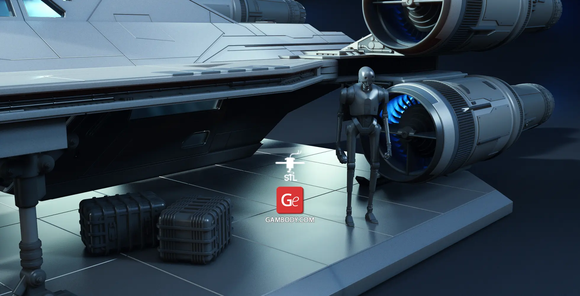
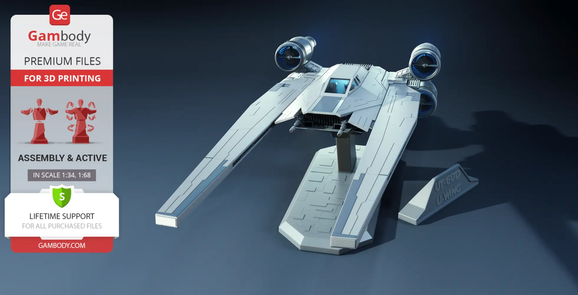
- Choice of a diorama display base or an in-flight stand.
- The assembly parts are connected using specially designed integrated connectors that fit securely into the corresponding slots. Optionally, for added strength and rigidity, the static connections can be glued together.
DLP/SLA
Eco parts
Assembly method
Connectors, Glue
Features
- Movable S-foils with integrated locking positions.
- Functional sliding side doors.
- LED-ready engine structure for optional custom lighting.
- Two cockpit canopy options: printable transparent canopy or framed insert for clear plastic.
- Removable top-rear battery compartment cover.
- Choice of a diorama display base or an in-flight stand.
- The assembly parts are connected using specially designed integrated connectors that fit securely into the corresponding slots. Optionally, for added strength and rigidity, the static connections can be glued together.
Additional details
Part of diorama
No
Add-on pack available
No
You will get instant access to the STL files of U-Wing Starfighter 3D Printer Files | Assembly + Action after completing your purchase. Simply add the model to your cart and check out using PayPal, credit or debit card, Apple Pay, Google Pay, Alipay, or other available payment methods.
Watch the assembly video for U-Wing Starfighter 3D Printer Files | Assembly + Action, and explore more tutorials, behind-the-scenes content, 3D printing timelapses, and painting guides on the official Gambody YouTube channel.
This 3D model comes with StereoLithography (.STL) files optimized for 3D printing. You'll get digital files, not a physical product
Before printing, take a look at Printing Details for recommended settings and tips to achieve better results.
U-Wing Starfighter 3D Printer Files | Assembly + Action includes 2 version(s) for the supported 3D printer type(s): FFF/FDM, DLP/SLA. Files are available for download after purchase.
See the Description and Specifications sections for more details about this model.
| File name | Size (mm | in) | Size(mb) | Printing Time / Filament | |||
|---|---|---|---|---|---|---|
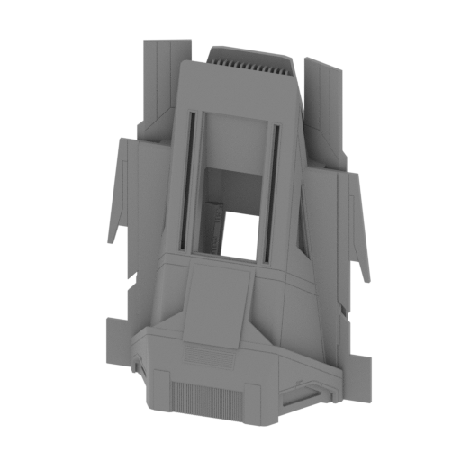 | _01_shipHull_a_FDM (repaired).stl 137.91 x 66.21 x 173.64 mm | 5.43 x 2.61 x 6.84 in | Size: 137.91 x 66.21 x 173.64 mm | 5.43 x 2.61 x 6.84 in | File size: 15.67 mb | Printing Time / Filament: 43 h 40 min / 27 m | ||
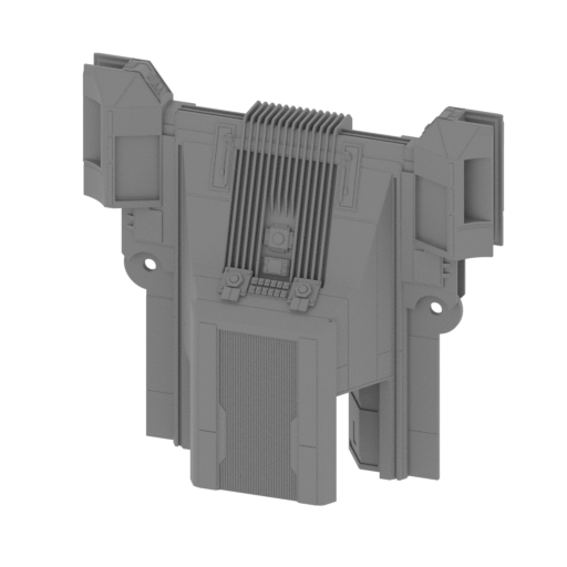 | _02_shipHull_b_FDM (repaired).stl 193.06 x 66.21 x 179 mm | 7.6 x 2.61 x 7.05 in | Size: 193.06 x 66.21 x 179 mm | 7.6 x 2.61 x 7.05 in | File size: 30.90 mb | Printing Time / Filament: 83 h 59 min / 55 m | ||
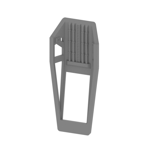 | _03_cockpitHatch_a_FDM (repaired).stl 48.27 x 15.87 x 109.36 mm | 1.9 x 0.62 x 4.31 in | Size: 48.27 x 15.87 x 109.36 mm | 1.9 x 0.62 x 4.31 in | File size: 2.10 mb | Printing Time / Filament: 4 h 49 min / 3 m | ||
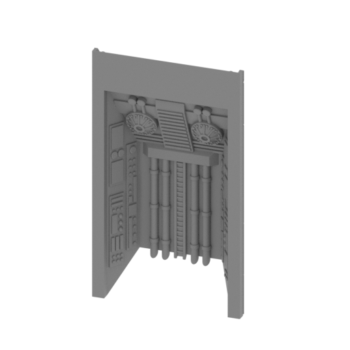 | _04_cockpitHatch_b_FDM (repaired).stl 48.27 x 15.87 x 81.44 mm | 1.9 x 0.62 x 3.21 in | Size: 48.27 x 15.87 x 81.44 mm | 1.9 x 0.62 x 3.21 in | File size: 37.43 mb | Printing Time / Filament: 5 h 14 min / 3 m | ||
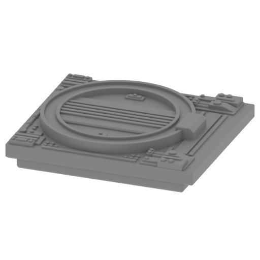 | _05_batteryHatch_a_FDM (repaired).stl 51.45 x 45.58 x 10.55 mm | 2.03 x 1.79 x 0.42 in | Size: 51.45 x 45.58 x 10.55 mm | 2.03 x 1.79 x 0.42 in | File size: 3.19 mb | Printing Time / Filament: 2 h 20 min / 1 m | ||
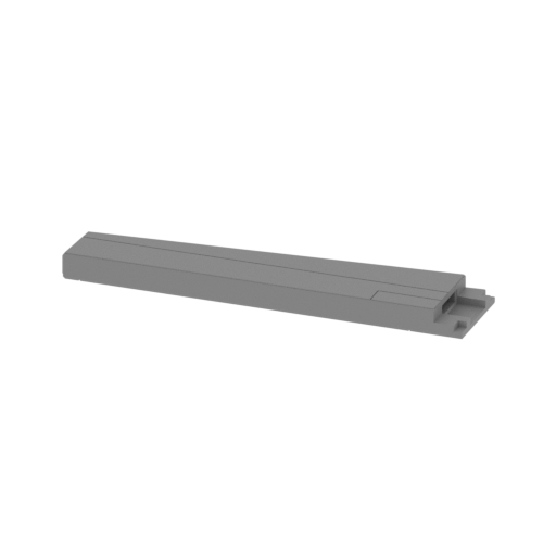 | _06_wing_a_L_FDM (repaired).stl 128.88 x 28.45 x 8.7 mm | 5.07 x 1.12 x 0.34 in | Size: 128.88 x 28.45 x 8.7 mm | 5.07 x 1.12 x 0.34 in | File size: 0.12 mb | Printing Time / Filament: 2 h 40 min / 2 m | ||
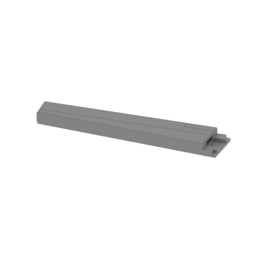 | _07_wing_b_R_FDM (repaired).stl 128.88 x 28.45 x 8.7 mm | 5.07 x 1.12 x 0.34 in | Size: 128.88 x 28.45 x 8.7 mm | 5.07 x 1.12 x 0.34 in | File size: 0.12 mb | Printing Time / Filament: 2 h 39 min / 2 m | ||
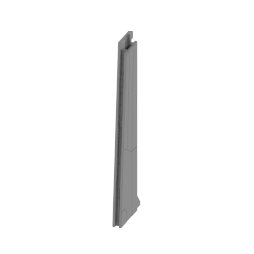 | _08_wing_c_L_FDM (repaired).stl 8.7 x 54.17 x 178 mm | 0.34 x 2.13 x 7.01 in | Size: 8.7 x 54.17 x 178 mm | 0.34 x 2.13 x 7.01 in | File size: 9.76 mb | Printing Time / Filament: 8 h 2 min / 4 m | ||
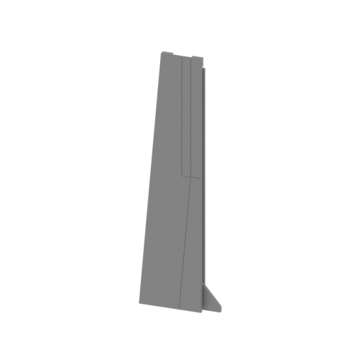 | _09_wing_d_R_FDM (repaired).stl 54.17 x 8.7 x 178 mm | 2.13 x 0.34 x 7.01 in | Size: 54.17 x 8.7 x 178 mm | 2.13 x 0.34 x 7.01 in | File size: 9.72 mb | Printing Time / Filament: 7 h 56 min / 4 m | ||
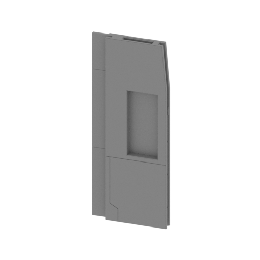 | _10_V1_wing_e_L_FDM (repaired).stl 57.16 x 8.7 x 140.38 mm | 2.25 x 0.34 x 5.53 in | Size: 57.16 x 8.7 x 140.38 mm | 2.25 x 0.34 x 5.53 in | File size: 4.01 mb | Printing Time / Filament: 8 h 32 min / 5 m | ||
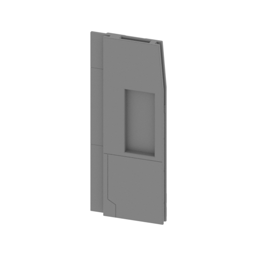 | _10_V2_wing_e_L_FDM (repaired).stl 57.16 x 8.96 x 140.39 mm | 2.25 x 0.35 x 5.53 in | Size: 57.16 x 8.96 x 140.39 mm | 2.25 x 0.35 x 5.53 in | File size: 4.03 mb | Printing Time / Filament: 8 h 31 min / 5 m | ||
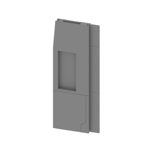 | _11_V1_wing_f_R_FDM (repaired).stl 57.16 x 8.7 x 140.38 mm | 2.25 x 0.34 x 5.53 in | Size: 57.16 x 8.7 x 140.38 mm | 2.25 x 0.34 x 5.53 in | File size: 4.03 mb | Printing Time / Filament: 8 h 48 min / 5 m | ||
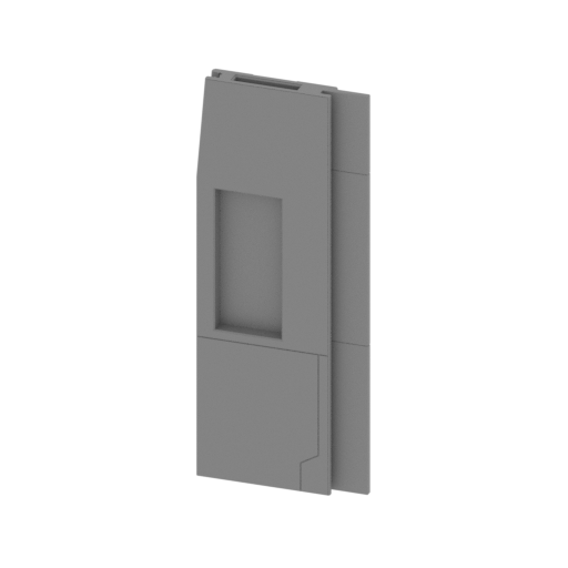 | _11_V2_wing_f_R_FDM (repaired).stl 57.15 x 8.95 x 140.38 mm | 2.25 x 0.35 x 5.53 in | Size: 57.15 x 8.95 x 140.38 mm | 2.25 x 0.35 x 5.53 in | File size: 4.03 mb | Printing Time / Filament: 8 h 36 min / 5 m | ||
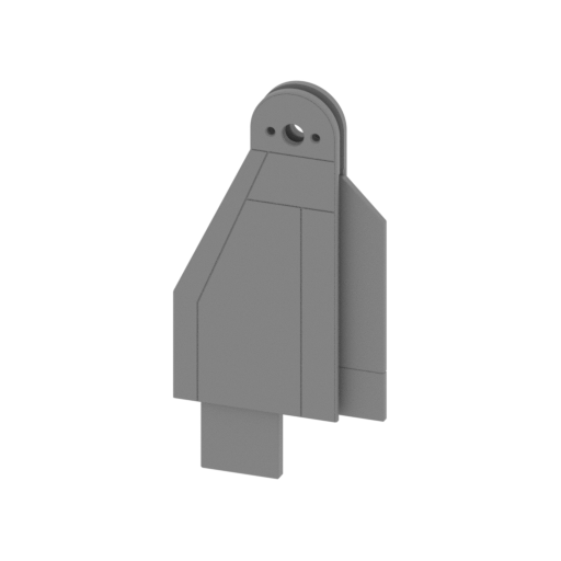 | _12_V1_wing_g_L_FDM (repaired).stl 57.15 x 8.7 x 112.77 mm | 2.25 x 0.34 x 4.44 in | Size: 57.15 x 8.7 x 112.77 mm | 2.25 x 0.34 x 4.44 in | File size: 6.40 mb | Printing Time / Filament: 5 h 36 min / 3 m | ||
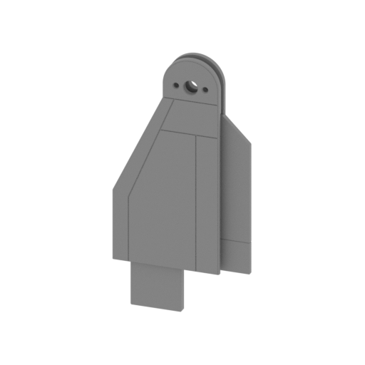 | _12_V2_wing_g_L_FDM (repaired).stl 57.15 x 8.95 x 112.77 mm | 2.25 x 0.35 x 4.44 in | Size: 57.15 x 8.95 x 112.77 mm | 2.25 x 0.35 x 4.44 in | File size: 6.36 mb | Printing Time / Filament: 5 h 12 min / 3 m | ||
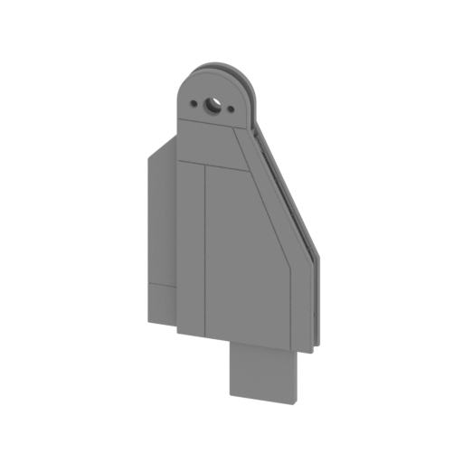 | _13_V1_wing_h_R_FDM (repaired).stl 57.15 x 8.7 x 112.77 mm | 2.25 x 0.34 x 4.44 in | Size: 57.15 x 8.7 x 112.77 mm | 2.25 x 0.34 x 4.44 in | File size: 6.34 mb | Printing Time / Filament: 5 h 51 min / 3 m | ||
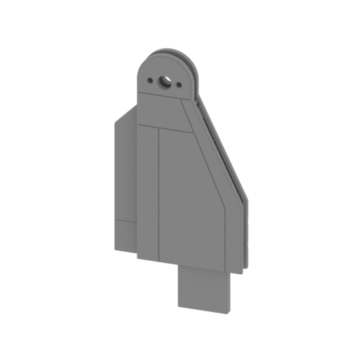 | _13_V2_wing_h_R_FDM (repaired).stl 57.15 x 8.95 x 112.77 mm | 2.25 x 0.35 x 4.44 in | Size: 57.15 x 8.95 x 112.77 mm | 2.25 x 0.35 x 4.44 in | File size: 6.33 mb | Printing Time / Filament: 5 h 34 min / 3 m | ||
 | _14_wingDetail_a_X2_FDM (repaired).stl 40 x 12 x 3.6 mm | 1.57 x 0.47 x 0.14 in | Size: 40 x 12 x 3.6 mm | 1.57 x 0.47 x 0.14 in | File size: 0.01 mb | Printing Time / Filament: 17 min / <1 m | ||
 | _15_wingDetail_b_X2_FDM (repaired).stl 40 x 21.78 x 3.6 mm | 1.57 x 0.86 x 0.14 in | Size: 40 x 21.78 x 3.6 mm | 1.57 x 0.86 x 0.14 in | File size: 0.01 mb | Printing Time / Filament: 28 min / <1 m | ||
 | _16_wingDetail_c_L_FDM (repaired).stl 49.28 x 22.58 x 5.5 mm | 1.94 x 0.89 x 0.22 in | Size: 49.28 x 22.58 x 5.5 mm | 1.94 x 0.89 x 0.22 in | File size: 0.04 mb | Printing Time / Filament: 46 min / <1 m | ||
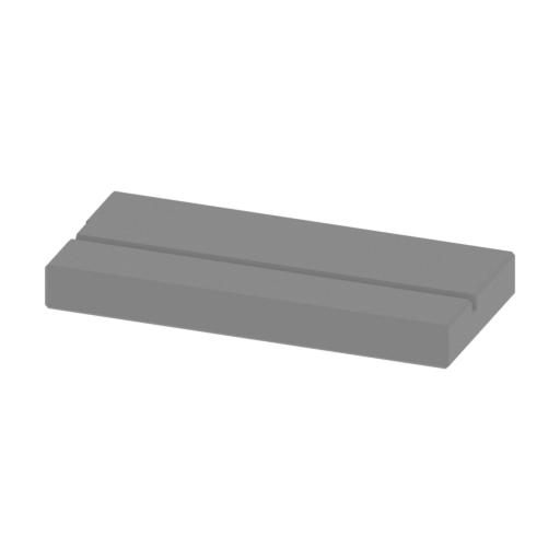 | _17_wingDetail_d_R_FDM (repaired).stl 49.28 x 22.58 x 5.5 mm | 1.94 x 0.89 x 0.22 in | Size: 49.28 x 22.58 x 5.5 mm | 1.94 x 0.89 x 0.22 in | File size: 0.04 mb | Printing Time / Filament: 46 min / <1 m | ||
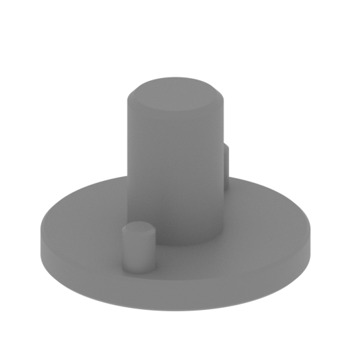 | _18_wingDetail_e_X2_FDM (repaired).stl 16 x 16 x 10.6 mm | 0.63 x 0.63 x 0.42 in | Size: 16 x 16 x 10.6 mm | 0.63 x 0.63 x 0.42 in | File size: 0.62 mb | Printing Time / Filament: 12 min / <1 m | ||
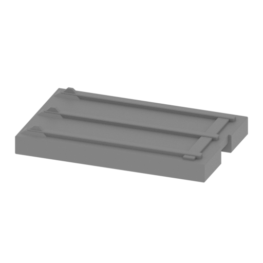 | _19_wingDetail_f_X2_FDM (repaired).stl 31.3 x 19.48 x 4.33 mm | 1.23 x 0.77 x 0.17 in | Size: 31.3 x 19.48 x 4.33 mm | 1.23 x 0.77 x 0.17 in | File size: 0.08 mb | Printing Time / Filament: 21 min / <1 m | ||
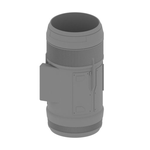 | _20_engine_a_L_FDM (repaired).stl 46.15 x 46.15 x 92.15 mm | 1.82 x 1.82 x 3.63 in | Size: 46.15 x 46.15 x 92.15 mm | 1.82 x 1.82 x 3.63 in | File size: 14.43 mb | Printing Time / Filament: 10 h 28 min / 6 m | ||
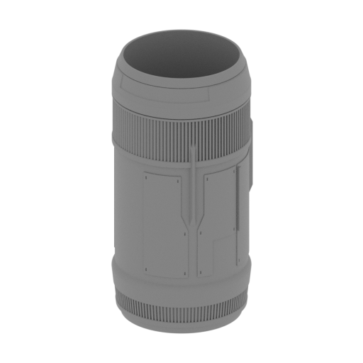 | _21_engine_b_L_FDM (repaired).stl 46.15 x 46.15 x 92.15 mm | 1.82 x 1.82 x 3.63 in | Size: 46.15 x 46.15 x 92.15 mm | 1.82 x 1.82 x 3.63 in | File size: 14.47 mb | Printing Time / Filament: 10 h 18 min / 6 m | ||
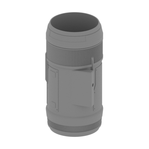 | _22_engine_c_R_FDM (repaired).stl 46.15 x 46.15 x 92.15 mm | 1.82 x 1.82 x 3.63 in | Size: 46.15 x 46.15 x 92.15 mm | 1.82 x 1.82 x 3.63 in | File size: 14.37 mb | Printing Time / Filament: 10 h 21 min / 6 m | ||
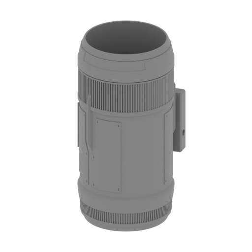 | _23_engine_d_R_FDM (repaired).stl 46.15 x 46.15 x 92.15 mm | 1.82 x 1.82 x 3.63 in | Size: 46.15 x 46.15 x 92.15 mm | 1.82 x 1.82 x 3.63 in | File size: 14.42 mb | Printing Time / Filament: 10 h 45 min / 6 m | ||
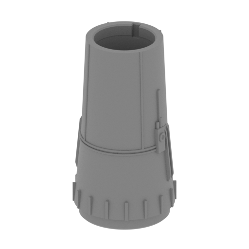 | _24_engine_e_L_FDM (repaired).stl 36.11 x 36.11 x 66.66 mm | 1.42 x 1.42 x 2.62 in | Size: 36.11 x 36.11 x 66.66 mm | 1.42 x 1.42 x 2.62 in | File size: 8.81 mb | Printing Time / Filament: 3 h 16 min / 2 m | ||
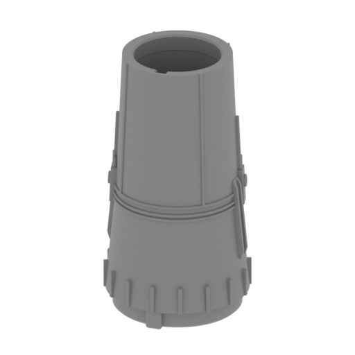 | _25_engine_f_L_FDM (repaired).stl 36.11 x 36.11 x 66.66 mm | 1.42 x 1.42 x 2.62 in | Size: 36.11 x 36.11 x 66.66 mm | 1.42 x 1.42 x 2.62 in | File size: 8.80 mb | Printing Time / Filament: 3 h 15 min / 2 m | ||
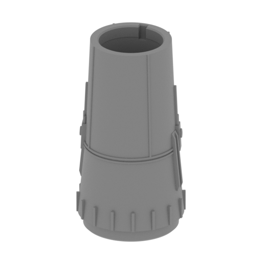 | _26_engine_g_R_FDM (repaired).stl 36.11 x 36.11 x 66.66 mm | 1.42 x 1.42 x 2.62 in | Size: 36.11 x 36.11 x 66.66 mm | 1.42 x 1.42 x 2.62 in | File size: 8.81 mb | Printing Time / Filament: 3 h 15 min / 2 m | ||
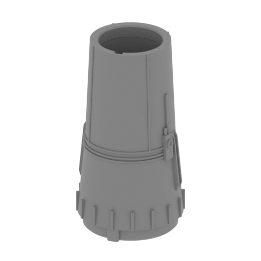 | _27_engine_h_R_FDM (repaired).stl 36.11 x 36.11 x 66.66 mm | 1.42 x 1.42 x 2.62 in | Size: 36.11 x 36.11 x 66.66 mm | 1.42 x 1.42 x 2.62 in | File size: 8.79 mb | Printing Time / Filament: 3 h 18 min / 2 m | ||
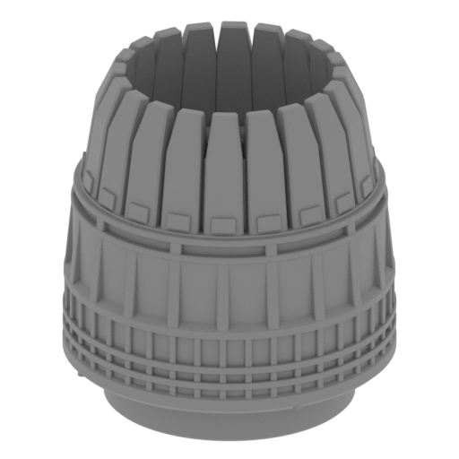 | _28_engine_i_X4_FDM (repaired).stl 28.08 x 28.08 x 29.69 mm | 1.11 x 1.11 x 1.17 in | Size: 28.08 x 28.08 x 29.69 mm | 1.11 x 1.11 x 1.17 in | File size: 6.82 mb | Printing Time / Filament: 1 h 47 min / 1 m | ||
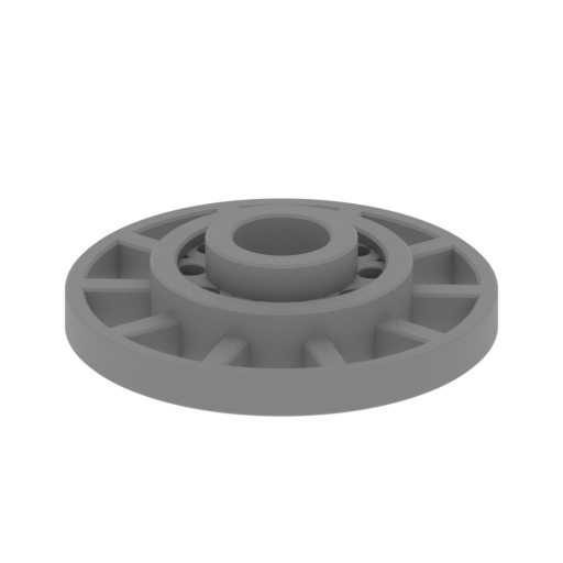 | _29_engine_j_X4_FDM (repaired).stl 18.75 x 18.75 x 4.46 mm | 0.74 x 0.74 x 0.18 in | Size: 18.75 x 18.75 x 4.46 mm | 0.74 x 0.74 x 0.18 in | File size: 4.88 mb | Printing Time / Filament: 17 min / <1 m | ||
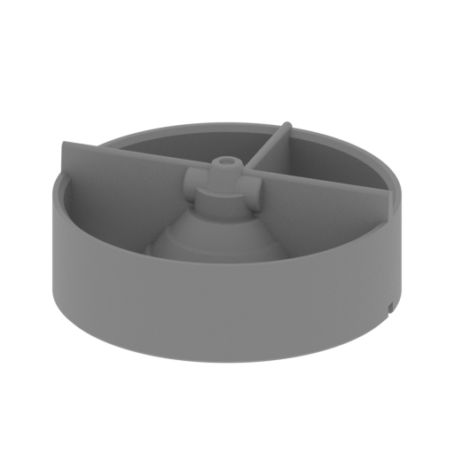 | _30_engine_k_X4_FDM (repaired).stl 38.13 x 38.13 x 15.69 mm | 1.5 x 1.5 x 0.62 in | Size: 38.13 x 38.13 x 15.69 mm | 1.5 x 1.5 x 0.62 in | File size: 4.11 mb | Printing Time / Filament: 1 h 28 min / 1 m | ||
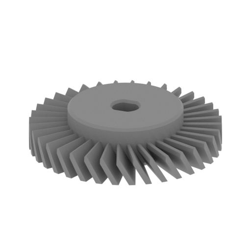 | _31_engine_l_X4_FDM (repaired).stl 35.33 x 35.33 x 8.04 mm | 1.39 x 1.39 x 0.32 in | Size: 35.33 x 35.33 x 8.04 mm | 1.39 x 1.39 x 0.32 in | File size: 1.42 mb | Printing Time / Filament: 60 min / <1 m | ||
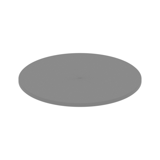 | _32_engine_m_X4_FDM (repaired).stl 35.47 x 35.47 x 1.2 mm | 1.4 x 1.4 x 0.05 in | Size: 35.47 x 35.47 x 1.2 mm | 1.4 x 1.4 x 0.05 in | File size: 0.72 mb | Printing Time / Filament: 21 min / <1 m | ||
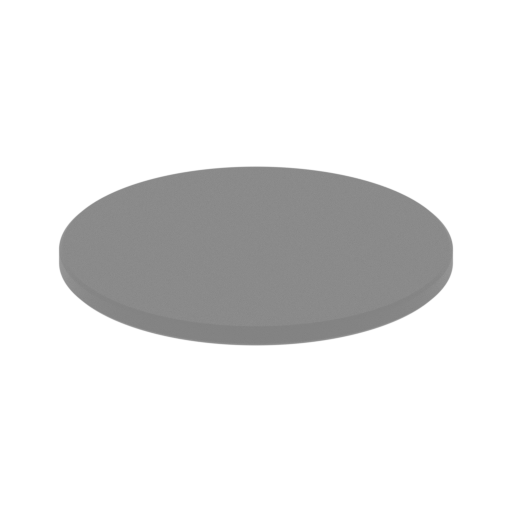 | _33_engine_n_X4_FDM (repaired).stl 18.75 x 18.75 x 1.01 mm | 0.74 x 0.74 x 0.04 in | Size: 18.75 x 18.75 x 1.01 mm | 0.74 x 0.74 x 0.04 in | File size: 0.43 mb | Printing Time / Filament: 5 min / <1 m | ||
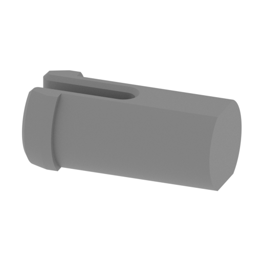 | _34_engine_o_X4_FDM (repaired).stl 10.1 x 5.23 x 4.07 mm | 0.4 x 0.21 x 0.16 in | Size: 10.1 x 5.23 x 4.07 mm | 0.4 x 0.21 x 0.16 in | File size: 0.20 mb | Printing Time / Filament: 4 min / <1 m | ||
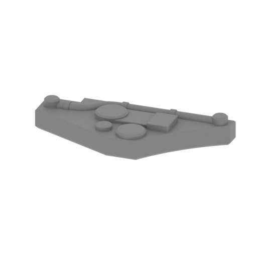 | _35_engine_p_X4_FDM (repaired).stl 19.93 x 8.41 x 2.95 mm | 0.78 x 0.33 x 0.12 in | Size: 19.93 x 8.41 x 2.95 mm | 0.78 x 0.33 x 0.12 in | File size: 1.05 mb | Printing Time / Filament: 5 min / <1 m | ||
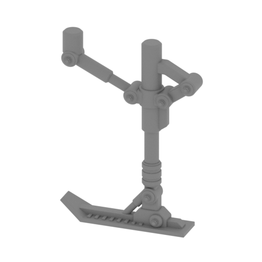 | _36_chassis_a_X2_FDM (repaired).stl 42.56 x 10.38 x 58.94 mm | 1.68 x 0.41 x 2.32 in | Size: 42.56 x 10.38 x 58.94 mm | 1.68 x 0.41 x 2.32 in | File size: 5.14 mb | Printing Time / Filament: 2 h 8 min / 1 m | ||
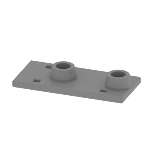 | _37_chassis_b_X2_FDM (repaired).stl 49.28 x 22.58 x 8 mm | 1.94 x 0.89 x 0.31 in | Size: 49.28 x 22.58 x 8 mm | 1.94 x 0.89 x 0.31 in | File size: 0.25 mb | Printing Time / Filament: 43 min / <1 m | ||
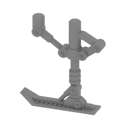 | _38_chassis_c_X2_FDM (repaired).stl 42.56 x 10.38 x 46.78 mm | 1.68 x 0.41 x 1.84 in | Size: 42.56 x 10.38 x 46.78 mm | 1.68 x 0.41 x 1.84 in | File size: 4.99 mb | Printing Time / Filament: 1 h 37 min / 1 m | ||
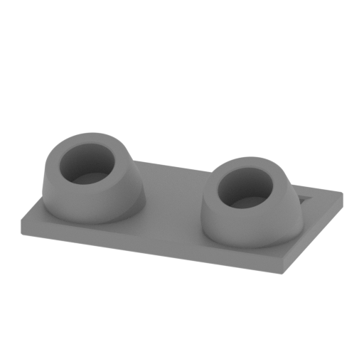 | _39_chassis_d_X2_FDM (repaired).stl 31.3 x 19.48 x 9.74 mm | 1.23 x 0.77 x 0.38 in | Size: 31.3 x 19.48 x 9.74 mm | 1.23 x 0.77 x 0.38 in | File size: 0.25 mb | Printing Time / Filament: 30 min / <1 m | ||
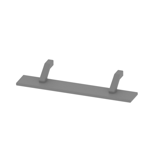 | _40_chassisHatch_a_X2_FDM (repaired).stl 49.28 x 14.47 x 6.92 mm | 1.94 x 0.57 x 0.27 in | Size: 49.28 x 14.47 x 6.92 mm | 1.94 x 0.57 x 0.27 in | File size: 0.02 mb | Printing Time / Filament: 16 min / <1 m | ||
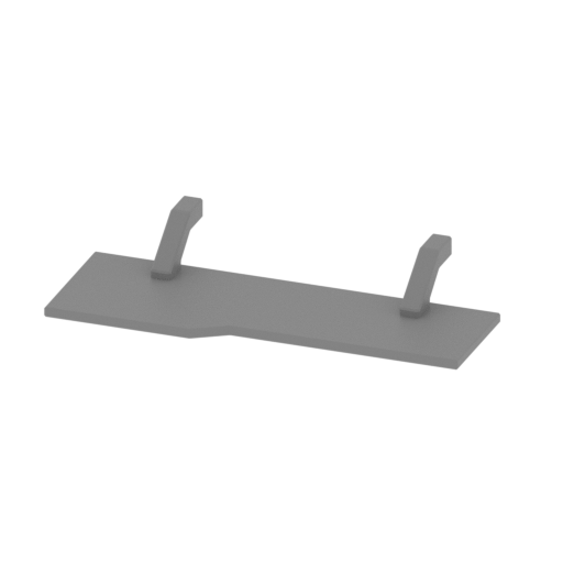 | _41_chassisHatch_b_L_FDM (repaired).stl 48.88 x 22.56 x 6.92 mm | 1.92 x 0.89 x 0.27 in | Size: 48.88 x 22.56 x 6.92 mm | 1.92 x 0.89 x 0.27 in | File size: 0.02 mb | Printing Time / Filament: 22 min / <1 m | ||
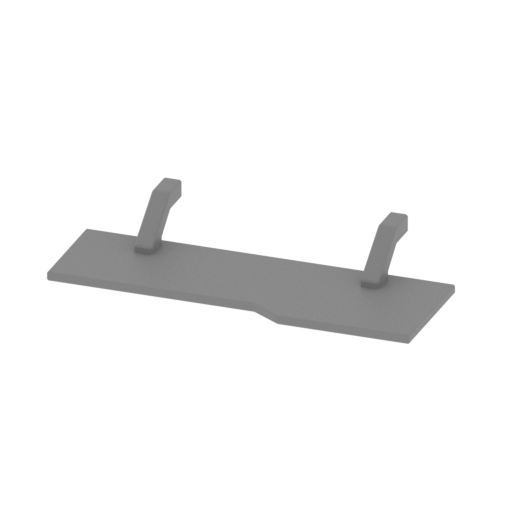 | _42_chassisHatch_c_R_FDM (repaired).stl 48.88 x 22.56 x 6.92 mm | 1.92 x 0.89 x 0.27 in | Size: 48.88 x 22.56 x 6.92 mm | 1.92 x 0.89 x 0.27 in | File size: 0.02 mb | Printing Time / Filament: 22 min / <1 m | ||
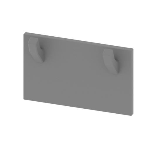 | _43_chassisHatch_d_L_FDM (repaired).stl 31.3 x 9.55 x 21.16 mm | 1.23 x 0.38 x 0.83 in | Size: 31.3 x 9.55 x 21.16 mm | 1.23 x 0.38 x 0.83 in | File size: 0.10 mb | Printing Time / Filament: 29 min / <1 m | ||
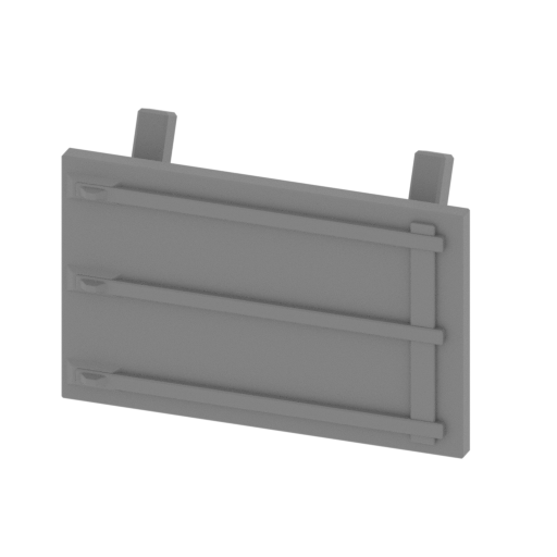 | _44_chassisHatch_e_R_FDM (repaired).stl 31.3 x 9.55 x 21.16 mm | 1.23 x 0.38 x 0.83 in | Size: 31.3 x 9.55 x 21.16 mm | 1.23 x 0.38 x 0.83 in | File size: 0.10 mb | Printing Time / Filament: 28 min / <1 m | ||
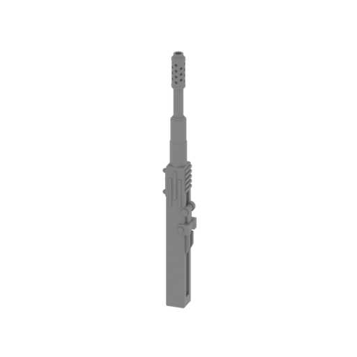 | _45_weapon_a_L_FDM (repaired).stl 9.93 x 8.42 x 89.13 mm | 0.39 x 0.33 x 3.51 in | Size: 9.93 x 8.42 x 89.13 mm | 0.39 x 0.33 x 3.51 in | File size: 3.50 mb | Printing Time / Filament: 1 h 15 min / <1 m | ||
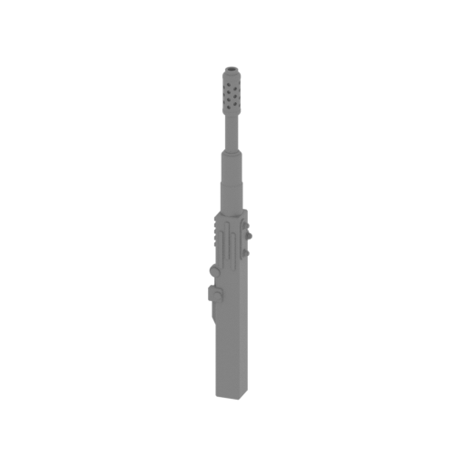 | _46_weapon_b_R_FDM (repaired).stl 9.93 x 8.42 x 89.13 mm | 0.39 x 0.33 x 3.51 in | Size: 9.93 x 8.42 x 89.13 mm | 0.39 x 0.33 x 3.51 in | File size: 3.50 mb | Printing Time / Filament: 1 h 15 min / <1 m | ||
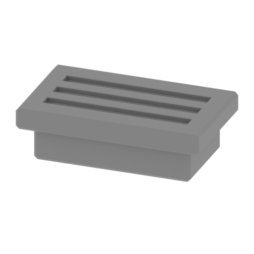 | _47_lamp_a_X2_FDM (repaired).stl 8.6 x 5.26 x 2.63 mm | 0.34 x 0.21 x 0.1 in | Size: 8.6 x 5.26 x 2.63 mm | 0.34 x 0.21 x 0.1 in | File size: 0.04 mb | Printing Time / Filament: 2 min / <1 m | ||
 | _48_lamp_b_X2_FDM (repaired).stl 68.1 x 18.33 x 1 mm | 2.68 x 0.72 x 0.04 in | Size: 68.1 x 18.33 x 1 mm | 2.68 x 0.72 x 0.04 in | File size: 0.01 mb | Printing Time / Filament: 4 min / <1 m | ||
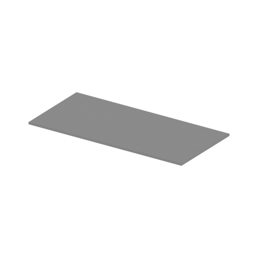 | _49_glass_a_FDM (repaired).stl 77.35 x 49.31 x 1 mm | 3.05 x 1.94 x 0.04 in | Size: 77.35 x 49.31 x 1 mm | 3.05 x 1.94 x 0.04 in | File size: 0.01 mb | Printing Time / Filament: 40 min / <1 m | ||
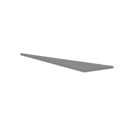 | _50_glass_b_X2_FDM (repaired).stl 39.77 x 8.13 x 1 mm | 1.57 x 0.32 x 0.04 in | Size: 39.77 x 8.13 x 1 mm | 1.57 x 0.32 x 0.04 in | File size: 0.01 mb | Printing Time / Filament: 4 min / <1 m | ||
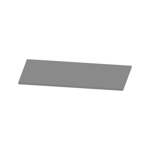 | _51_glass_c_FDM (repaired).stl 51.78 x 34.74 x 1 mm | 2.04 x 1.37 x 0.04 in | Size: 51.78 x 34.74 x 1 mm | 2.04 x 1.37 x 0.04 in | File size: 0.01 mb | Printing Time / Filament: 21 min / <1 m | ||
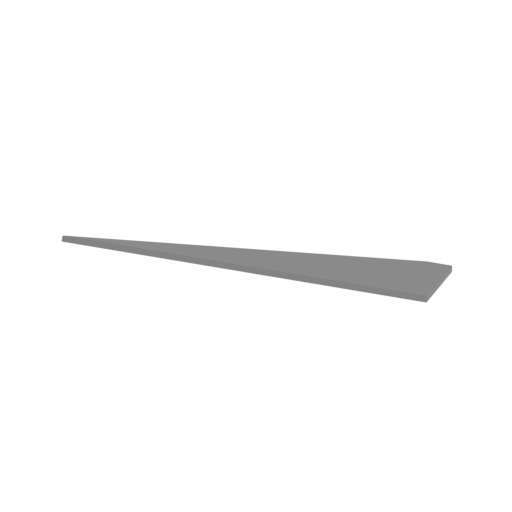 | _52_glass_d_X2_FDM (repaired).stl 54.47 x 11.08 x 1 mm | 2.14 x 0.44 x 0.04 in | Size: 54.47 x 11.08 x 1 mm | 2.14 x 0.44 x 0.04 in | File size: 0.01 mb | Printing Time / Filament: 6 min / <1 m | ||
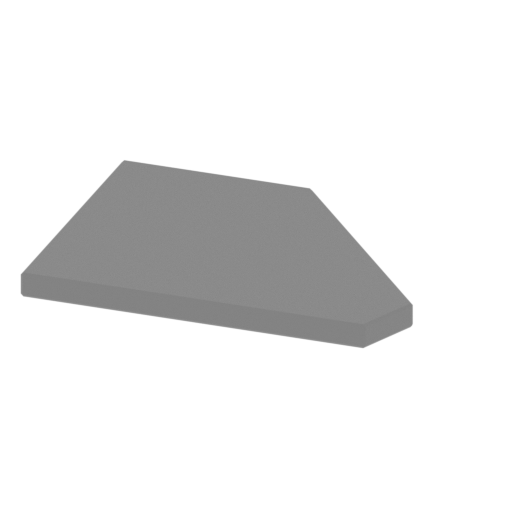 | _53_glass_e_X2_FDM (repaired).stl 15.01 x 11.29 x 1 mm | 0.59 x 0.44 x 0.04 in | Size: 15.01 x 11.29 x 1 mm | 0.59 x 0.44 x 0.04 in | File size: 0.01 mb | Printing Time / Filament: 3 min / <1 m | ||
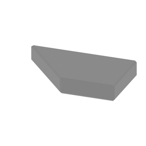 | _54_glass_f_X2_FDM (repaired).stl 6.45 x 3.86 x 1 mm | 0.25 x 0.15 x 0.04 in | Size: 6.45 x 3.86 x 1 mm | 0.25 x 0.15 x 0.04 in | File size: 0.01 mb | Printing Time / Filament: 1 min / <1 m | ||
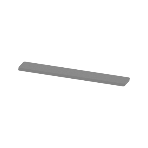 | _55_glass_g_X2_FDM (repaired).stl 44.76 x 6.91 x 1 mm | 1.76 x 0.27 x 0.04 in | Size: 44.76 x 6.91 x 1 mm | 1.76 x 0.27 x 0.04 in | File size: 0.07 mb | Printing Time / Filament: 6 min / <1 m | ||
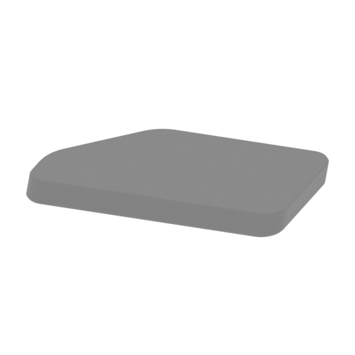 | _56_glass_h_L_FDM (repaired).stl 13.1 x 8.4 x 1 mm | 0.52 x 0.33 x 0.04 in | Size: 13.1 x 8.4 x 1 mm | 0.52 x 0.33 x 0.04 in | File size: 0.10 mb | Printing Time / Filament: 2 min / <1 m | ||
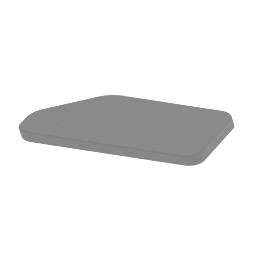 | _57_glass_i_R_FDM (repaired).stl 13.1 x 8.4 x 1 mm | 0.52 x 0.33 x 0.04 in | Size: 13.1 x 8.4 x 1 mm | 0.52 x 0.33 x 0.04 in | File size: 0.10 mb | Printing Time / Filament: 2 min / <1 m | ||
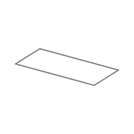 | _58_glassFrame_a_FDM (repaired).stl 77.34 x 49.3 x 0.8 mm | 3.04 x 1.94 x 0.03 in | Size: 77.34 x 49.3 x 0.8 mm | 3.04 x 1.94 x 0.03 in | File size: 0.01 mb | Printing Time / Filament: 4 min / <1 m | ||
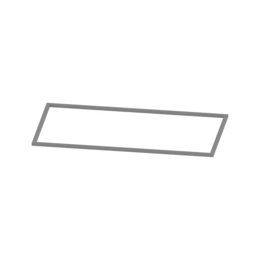 | _59_glassFrame_b_FDM (repaired).stl 51.81 x 34.77 x 0.8 mm | 2.04 x 1.37 x 0.03 in | Size: 51.81 x 34.77 x 0.8 mm | 2.04 x 1.37 x 0.03 in | File size: 0.01 mb | Printing Time / Filament: 4 min / <1 m | ||
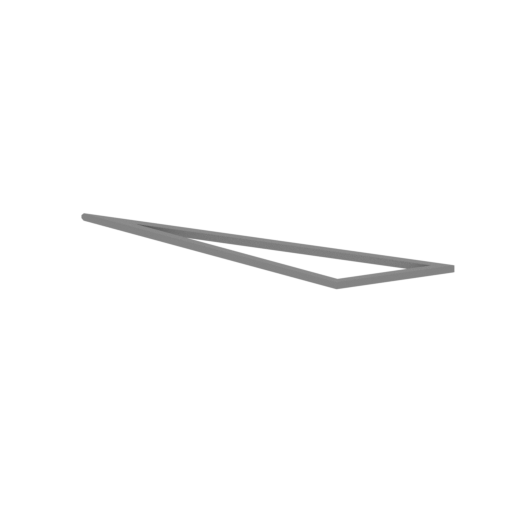 | _60_glassFrame_c_X2_FDM (repaired).stl 40.08 x 8.15 x 0.8 mm | 1.58 x 0.32 x 0.03 in | Size: 40.08 x 8.15 x 0.8 mm | 1.58 x 0.32 x 0.03 in | File size: 0.02 mb | Printing Time / Filament: 2 min / <1 m | ||
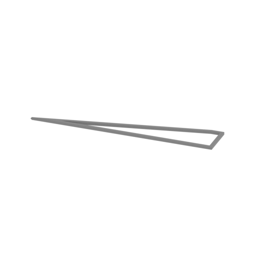 | _61_glassFrame_d_X2_FDM (repaired).stl 54.55 x 11.08 x 0.8 mm | 2.15 x 0.44 x 0.03 in | Size: 54.55 x 11.08 x 0.8 mm | 2.15 x 0.44 x 0.03 in | File size: 0.02 mb | Printing Time / Filament: 3 min / <1 m | ||
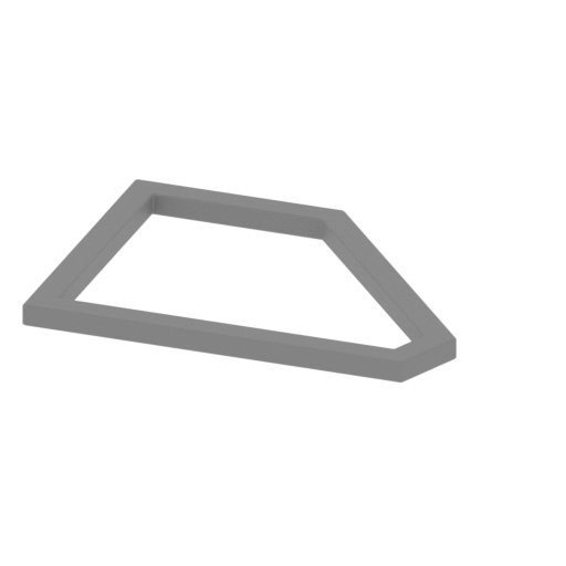 | _62_glassFrame_e_X2_FDM (repaired).stl 15.03 x 11.29 x 0.8 mm | 0.59 x 0.44 x 0.03 in | Size: 15.03 x 11.29 x 0.8 mm | 0.59 x 0.44 x 0.03 in | File size: 0.02 mb | Printing Time / Filament: 1 min / <1 m | ||
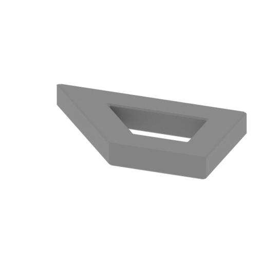 | _63_glassFrame_f_X2_FDM (repaired).stl 6.5 x 3.86 x 0.8 mm | 0.26 x 0.15 x 0.03 in | Size: 6.5 x 3.86 x 0.8 mm | 0.26 x 0.15 x 0.03 in | File size: 0.01 mb | Printing Time / Filament: 1 min / <1 m | ||
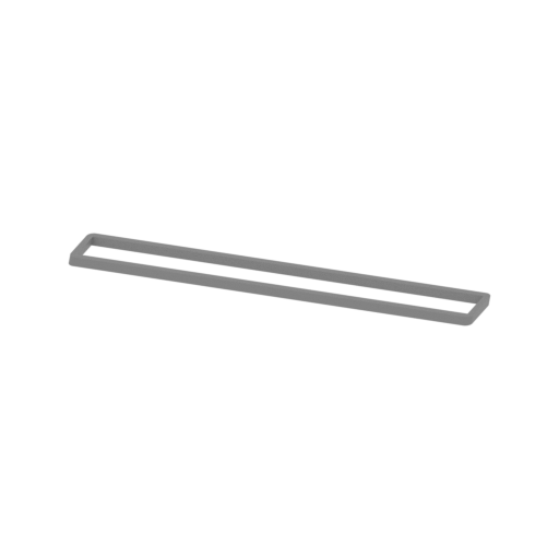 | _64_glassFrame_g_X2_FDM (repaired).stl 44.76 x 6.92 x 0.8 mm | 1.76 x 0.27 x 0.03 in | Size: 44.76 x 6.92 x 0.8 mm | 1.76 x 0.27 x 0.03 in | File size: 0.05 mb | Printing Time / Filament: 2 min / <1 m | ||
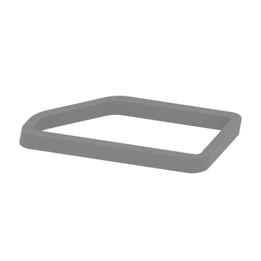 | _65_glassFrame_h_L_FDM (repaired).stl 13.1 x 8.41 x 0.8 mm | 0.52 x 0.33 x 0.03 in | Size: 13.1 x 8.41 x 0.8 mm | 0.52 x 0.33 x 0.03 in | File size: 0.05 mb | Printing Time / Filament: 1 min / <1 m | ||
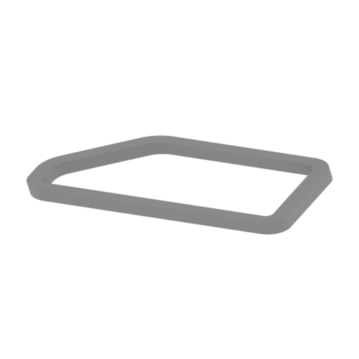 | _66_glassFrame_i_R_FDM (repaired).stl 13.1 x 8.41 x 0.8 mm | 0.52 x 0.33 x 0.03 in | Size: 13.1 x 8.41 x 0.8 mm | 0.52 x 0.33 x 0.03 in | File size: 0.05 mb | Printing Time / Filament: 1 min / <1 m | ||
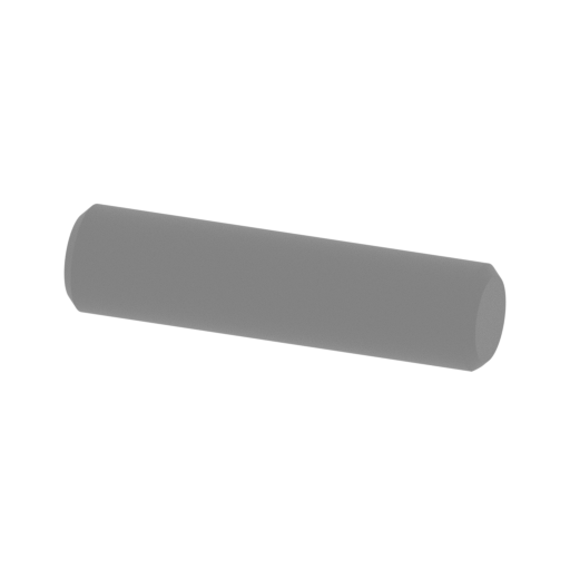 | _67_pin_V1_X2_FDM (repaired).stl 20 x 5 x 4.73 mm | 0.79 x 0.2 x 0.19 in | Size: 20 x 5 x 4.73 mm | 0.79 x 0.2 x 0.19 in | File size: 0.10 mb | Printing Time / Filament: 6 min / <1 m | ||
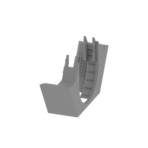 | _68_interior_a_FDM (repaired).stl 26.39 x 95.09 x 53.01 mm | 1.04 x 3.74 x 2.09 in | Size: 26.39 x 95.09 x 53.01 mm | 1.04 x 3.74 x 2.09 in | File size: 6.99 mb | Printing Time / Filament: 3 h 47 min / 2 m | ||
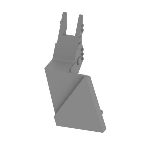 | _69_interior_b_L_FDM (repaired).stl 22.04 x 36.01 x 53.01 mm | 0.87 x 1.42 x 2.09 in | Size: 22.04 x 36.01 x 53.01 mm | 0.87 x 1.42 x 2.09 in | File size: 3.17 mb | Printing Time / Filament: 1 h 30 min / 1 m | ||
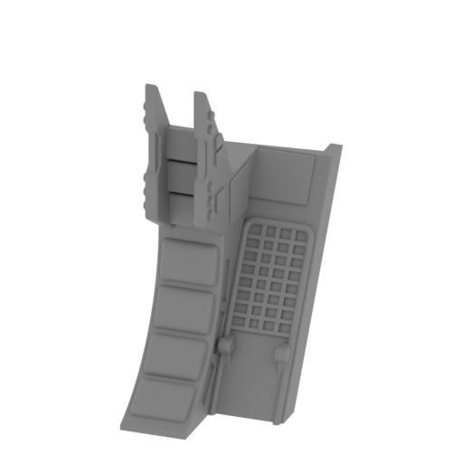 | _70_interior_c_R_FDM (repaired).stl 22.04 x 36.01 x 53.01 mm | 0.87 x 1.42 x 2.09 in | Size: 22.04 x 36.01 x 53.01 mm | 0.87 x 1.42 x 2.09 in | File size: 3.18 mb | Printing Time / Filament: 1 h 32 min / 1 m | ||
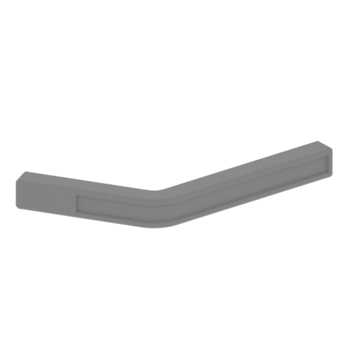 | _71_interior_d_X4_FDM (repaired).stl 27.11 x 19.71 x 3.2 mm | 1.07 x 0.78 x 0.13 in | Size: 27.11 x 19.71 x 3.2 mm | 1.07 x 0.78 x 0.13 in | File size: 0.04 mb | Printing Time / Filament: 5 min / <1 m | ||
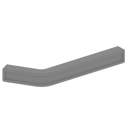 | _72_interior_e_X2_FDM (repaired).stl 21.25 x 19.71 x 3.2 mm | 0.84 x 0.78 x 0.13 in | Size: 21.25 x 19.71 x 3.2 mm | 0.84 x 0.78 x 0.13 in | File size: 0.04 mb | Printing Time / Filament: 4 min / <1 m | ||
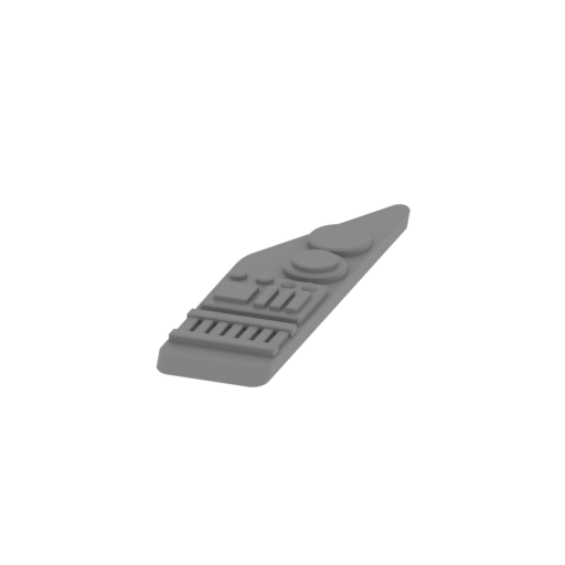 | _73_interior_f_L_FDM (repaired).stl 6.7 x 24.51 x 1.82 mm | 0.26 x 0.96 x 0.07 in | Size: 6.7 x 24.51 x 1.82 mm | 0.26 x 0.96 x 0.07 in | File size: 0.54 mb | Printing Time / Filament: 4 min / <1 m | ||
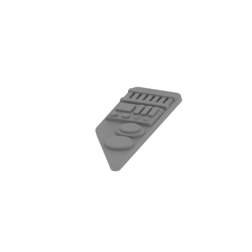 | _74_interior_g_R_FDM (repaired).stl 6.7 x 24.51 x 1.82 mm | 0.26 x 0.96 x 0.07 in | Size: 6.7 x 24.51 x 1.82 mm | 0.26 x 0.96 x 0.07 in | File size: 0.58 mb | Printing Time / Filament: 4 min / <1 m | ||
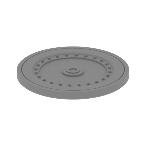 | _75_engineHatch_a_FDM (repaired).stl 42.32 x 42.32 x 3.4 mm | 1.67 x 1.67 x 0.13 in | Size: 42.32 x 42.32 x 3.4 mm | 1.67 x 1.67 x 0.13 in | File size: 7.84 mb | Printing Time / Filament: 50 min / <1 m | ||
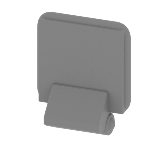 | _76_seat_a_X4_FDM (repaired).stl 10.51 x 4.59 x 12.81 mm | 0.41 x 0.18 x 0.5 in | Size: 10.51 x 4.59 x 12.81 mm | 0.41 x 0.18 x 0.5 in | File size: 1.83 mb | Printing Time / Filament: 8 min / <1 m | ||
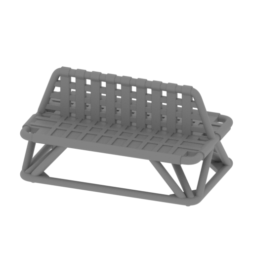 | _77_seat_b_FDM (repaired).stl 39.71 x 24.19 x 22.25 mm | 1.56 x 0.95 x 0.88 in | Size: 39.71 x 24.19 x 22.25 mm | 1.56 x 0.95 x 0.88 in | File size: 6.57 mb | Printing Time / Filament: 1 h 40 min / 1 m | ||
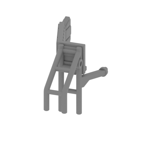 | _78_seat_c_L_FDM (repaired).stl 25.85 x 48.45 x 31.51 mm | 1.02 x 1.91 x 1.24 in | Size: 25.85 x 48.45 x 31.51 mm | 1.02 x 1.91 x 1.24 in | File size: 4.10 mb | Printing Time / Filament: 1 h 26 min / 1 m | ||
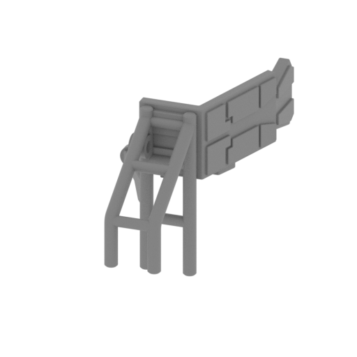 | _79_seat_d_R_FDM (repaired).stl 25.85 x 48.45 x 31.51 mm | 1.02 x 1.91 x 1.24 in | Size: 25.85 x 48.45 x 31.51 mm | 1.02 x 1.91 x 1.24 in | File size: 4.10 mb | Printing Time / Filament: 1 h 27 min / 1 m | ||
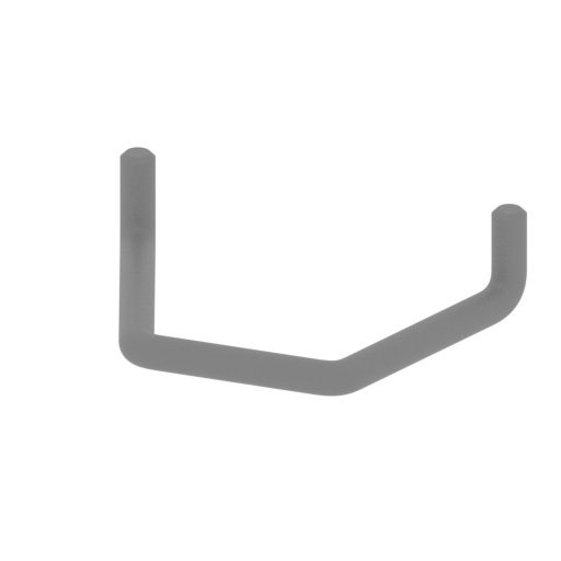 | _80_pipe_a_FDM (repaired).stl 24.31 x 15.96 x 6.43 mm | 0.96 x 0.63 x 0.25 in | Size: 24.31 x 15.96 x 6.43 mm | 0.96 x 0.63 x 0.25 in | File size: 2.20 mb | Printing Time / Filament: 5 min / <1 m | ||
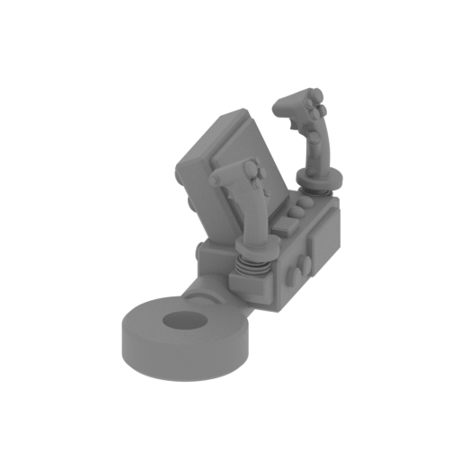 | _81_controlPanel_a_L_FDM (repaired).stl 6.82 x 17.48 x 9.14 mm | 0.27 x 0.69 x 0.36 in | Size: 6.82 x 17.48 x 9.14 mm | 0.27 x 0.69 x 0.36 in | File size: 5.30 mb | Printing Time / Filament: 11 min / <1 m | ||
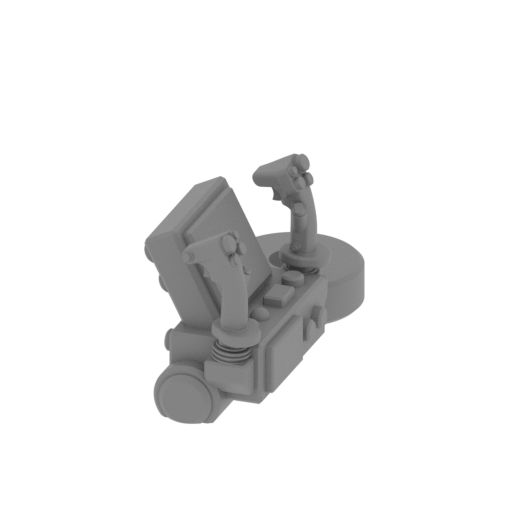 | _82_controlPanel_b_R_FDM (repaired).stl 6.82 x 17.48 x 9.14 mm | 0.27 x 0.69 x 0.36 in | Size: 6.82 x 17.48 x 9.14 mm | 0.27 x 0.69 x 0.36 in | File size: 5.32 mb | Printing Time / Filament: 10 min / <1 m | ||
 | _83_bodyPart_a_FDM (repaired).stl 20 x 42 x 3 mm | 0.79 x 1.65 x 0.12 in | Size: 20 x 42 x 3 mm | 0.79 x 1.65 x 0.12 in | File size: 0.01 mb | Printing Time / Filament: 26 min / <1 m | ||
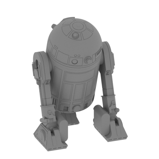 | _84_r2d2_a_FDM (repaired).stl 26.56 x 26.91 x 33.18 mm | 1.05 x 1.06 x 1.31 in | Size: 26.56 x 26.91 x 33.18 mm | 1.05 x 1.06 x 1.31 in | File size: 15.20 mb | Printing Time / Filament: 1 h 54 min / 1 m | ||
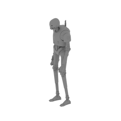 | _85_K_2SO_a_FDM (repaired).stl 17.97 x 21.04 x 63.95 mm | 0.71 x 0.83 x 2.52 in | Size: 17.97 x 21.04 x 63.95 mm | 0.71 x 0.83 x 2.52 in | File size: 74.04 mb | Printing Time / Filament: 1 h 51 min / 1 m | ||
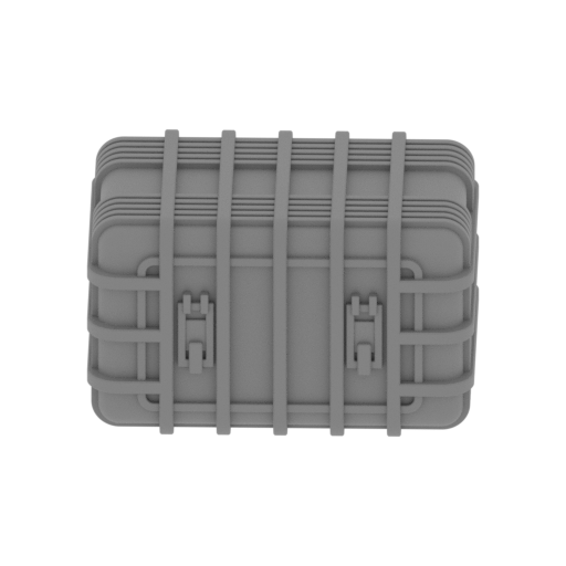 | _86_box_a_X5_FDM (repaired).stl 32.15 x 26.66 x 17.48 mm | 1.27 x 1.05 x 0.69 in | Size: 32.15 x 26.66 x 17.48 mm | 1.27 x 1.05 x 0.69 in | File size: 3.32 mb | Printing Time / Filament: 1 h 16 min / 1 m | ||
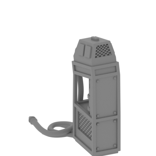 | _87_weldingMachine_a_FDM (repaired).stl 32.73 x 30.74 x 34.23 mm | 1.29 x 1.21 x 1.35 in | Size: 32.73 x 30.74 x 34.23 mm | 1.29 x 1.21 x 1.35 in | File size: 8.03 mb | Printing Time / Filament: 1 h 3 min / <1 m | ||
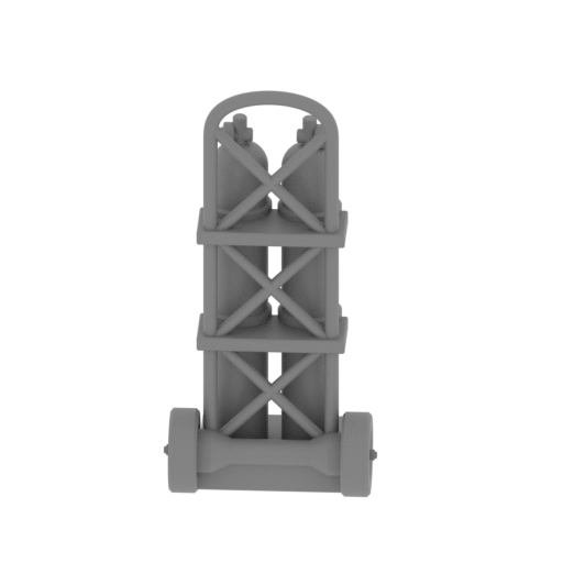 | _88_gasCylinders_a_FDM (repaired).stl 30.43 x 28.51 x 61.18 mm | 1.2 x 1.12 x 2.41 in | Size: 30.43 x 28.51 x 61.18 mm | 1.2 x 1.12 x 2.41 in | File size: 5.99 mb | Printing Time / Filament: 2 h 31 min / 1 m | ||
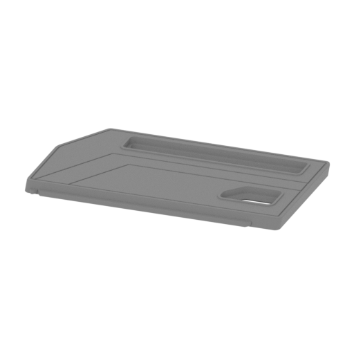 | _89_door_a_L_FDM (repaired).stl 64.95 x 38.33 x 2.9 mm | 2.56 x 1.51 x 0.11 in | Size: 64.95 x 38.33 x 2.9 mm | 2.56 x 1.51 x 0.11 in | File size: 1.20 mb | Printing Time / Filament: 1 h 2 min / 1 m | ||
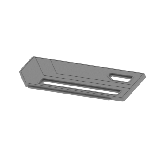 | _90_door_b_R_FDM (repaired).stl 64.95 x 38.33 x 2.9 mm | 2.56 x 1.51 x 0.11 in | Size: 64.95 x 38.33 x 2.9 mm | 2.56 x 1.51 x 0.11 in | File size: 1.21 mb | Printing Time / Filament: 1 h 2 min / 1 m | ||
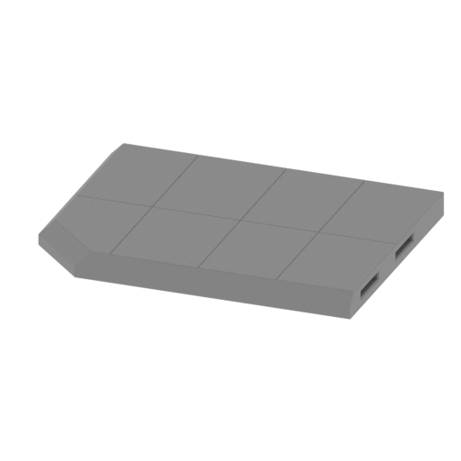 | _91_stand_a_X4_FDM (repaired).stl 170 x 130 x 12.35 mm | 6.69 x 5.12 x 0.49 in | Size: 170 x 130 x 12.35 mm | 6.69 x 5.12 x 0.49 in | File size: 0.04 mb | Printing Time / Filament: 21 h 7 min / 12 m | ||
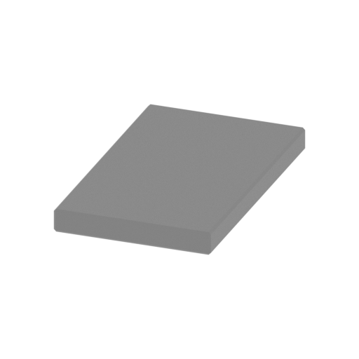 | _92_stand_b_X8_FDM (repaired).stl 24.26 x 40 x 3.6 mm | 0.96 x 1.57 x 0.14 in | Size: 24.26 x 40 x 3.6 mm | 0.96 x 1.57 x 0.14 in | File size: 0.01 mb | Printing Time / Filament: 31 min / <1 m | ||
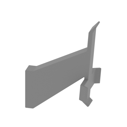 | _93_stand_c_FDM (repaired).stl 105.68 x 72.68 x 138 mm | 4.16 x 2.86 x 5.43 in | Size: 105.68 x 72.68 x 138 mm | 4.16 x 2.86 x 5.43 in | File size: 0.06 mb | Printing Time / Filament: 12 h 37 min / 9 m | ||
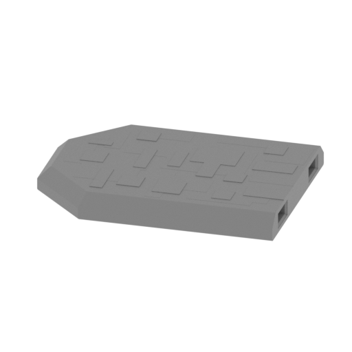 | _94_stand_d_FDM (repaired).stl 166.69 x 130.33 x 16.45 mm | 6.56 x 5.13 x 0.65 in | Size: 166.69 x 130.33 x 16.45 mm | 6.56 x 5.13 x 0.65 in | File size: 0.12 mb | Printing Time / Filament: 20 h 55 min / 12 m | ||
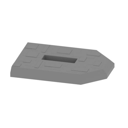 | _95_stand_e_FDM (repaired).stl 166.69 x 130.33 x 16.45 mm | 6.56 x 5.13 x 0.65 in | Size: 166.69 x 130.33 x 16.45 mm | 6.56 x 5.13 x 0.65 in | File size: 0.11 mb | Printing Time / Filament: 20 h 47 min / 12 m | ||
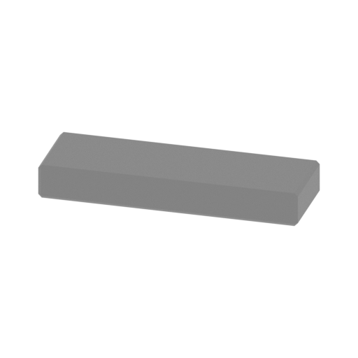 | _96_stand_f_X2_FDM (repaired).stl 61.38 x 25.01 x 8 mm | 2.42 x 0.98 x 0.31 in | Size: 61.38 x 25.01 x 8 mm | 2.42 x 0.98 x 0.31 in | File size: 0.01 mb | Printing Time / Filament: 60 min / 1 m | ||
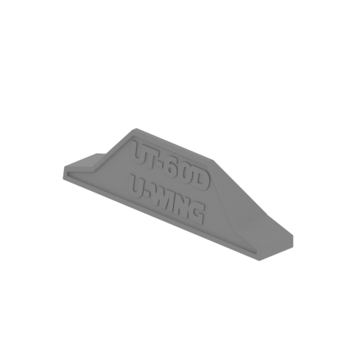 | _97_logo_a_FDM (repaired).stl 165.93 x 97.91 x 47.08 mm | 6.53 x 3.85 x 1.85 in | Size: 165.93 x 97.91 x 47.08 mm | 6.53 x 3.85 x 1.85 in | File size: 0.54 mb | Printing Time / Filament: 9 h 32 min / 5 m | ||
 | Keychain (repaired).stlCalculation... | Size:Calculation... | File size: 0.01 mb | Printing Time / Filament: Calculation... | ||
 | Tag (repaired).stlCalculation... | Size:Calculation... | File size: 0.01 mb | Printing Time / Filament: Calculation... | ||
3D model history
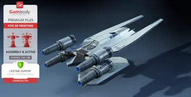
The U-Wing Starfighter showcases a different side of the Rebel Alliance. Rather than an agile dogfighter, the UT-60D was built as an assault transport and gunship, designed to carry troops through heavy Imperial fire, deploy them directly into combat, and provide close air support when it mattered most. Introduced in Rogue One: A Star Wars Story, its distinctive swing-wing design and rugged, utilitarian silhouette quickly became a memorable part of the Star Wars universe. Built to complete difficult missions instead of stealing the spotlight, it remains a favorite among fans of spacecraft 3D models and sci-fi 3D models.
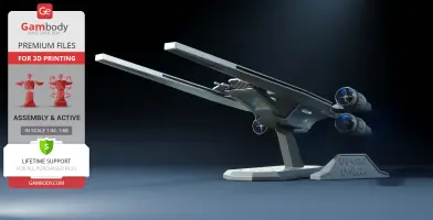
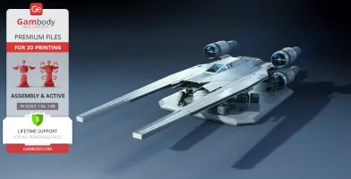
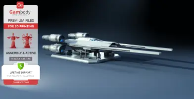
This U-Wing 3D model captures that practical Rebel engineering in a highly detailed build for makers and collectors. The U-Wing STL features movable S-foils with locking positions, sliding side doors, LED-ready engines, and two cockpit canopy options for either transparent prints or custom-cut plastic inserts. Complete with a removable battery compartment cover and a choice of an in-flight stand or a diorama base, this U-Wing 3D print project blends functional design with display appeal. Whether you're expanding a fleet of spaceship STL projects or searching for an authentic starfighter 3D model, it makes a worthy addition to any collection of movie 3D models and premium starship 3D print model builds.
3D printing model features
Model-specific features:
- Articulating S-foils can sweep back into attack configuration and lock securely in multiple positions.
- Functional sliding side doors allow the troop compartment to be displayed open or closed.
- LED-ready engine structure is designed for optional custom backlighting.
- Includes two cockpit canopy options: a printable transparent version or a framed insert designed for custom-cut clear plastic.
- Features a removable top-rear battery compartment cover for convenient access during LED installation.
- Comes with two display options: a detailed diorama base or a dynamic in-flight stand.
Printing & assembly details:
- Provided as error-free STL files compatible with most 3D printers;
- Optimized part division minimizes support material and ensures smooth and precise surface detailing;
- The assembly parts in the FFF/FDM version come in the recommended print orientations for easy bed placement;
- Assembly manual in PDF and video formats is included for the FFF/FDM and DLP/SLA versions;
- The model is available in recommended scales — 1:34 for the FFF/FDM version and 1:68 for the DLP/SLA versions.
What will you get after purchase?
- 2 versions of U-Wing StarfighterSTL files for FFF/FDM and DLP/SLA — files for all versions are available for download after the purchase;
- STL files of high-poly U-Wing Starfighter model for 3D printing consist of 184 files;
- Sizes for:
- FFF/FDM Model size (Folded wings): 250 mm wide, 104 mm high, 704 mm deep;
- FFF/FDM Model size (Extended wings): 886 mm wide, 104 mm high, 667 mm deep;
- FFF/FDM Platform size (In flight stand): 120 mm wide, 110 mm high, 320 mm deep;
- FFF/FDM Platform size (Diorama): 260 mm wide, 76 mm high, 340 mm deep;
- DLP/SLA Model size (Folded wings): 125 mm wide, 52 mm high, 352 mm deep;
- DLP/SLA Model size (Extended wings): 443 mm wide, 52 mm high, 334 mm deep;
- DLP/SLA Platform size (In flight stand): 60 mm wide, 55 mm high, 160 mm deep;
- DLP/SLA Platform size (Diorama): 130 mm wide, 38 mm high, 170 mm deep;
- Assembly Manual for 1.0 FFF/FDM and 1.0 DLP/SLA versions in PDF and video formats;
- Detailed settings that we provide as a recommendation for Bambu Studio, Cura, Orca Slicer, PrusaSlicer, Simplify3D, and Slic3r for the best print;
- Full technical support from the Gambody Support Team.
Below you'll find detailed slicing settings for Bambu Studio 2.0+, Orca Slicer 2.0+, UltiMaker Cura 5.0+, PrusaSlicer 2.0+, Slic3r 1.3+, Simplify3D 5.0+ to help you get the best results when printing this model. These settings are optimized specifically for this 3D model, but please note they may need slight adjustments depending on your printer or filament. When in doubt, refer to your printer's user manual.
To avoid printing issues and achieve the best quality, we highly recommend applying the following settings:
 Bambu Studio 2.0+
 For better quality use 0.12 mm layer height, for fast printing use 0.2 mm layer height. For pins and the Ge connectors, use 0.2 layer height.
120-150% of your Layer Height
But you can paint the seam if you want.
You have to calibrate this parameter
You have to calibrate this parameter
You have to calibrate this parameter
For pins and power elements of the structure, such as the vehicle frame, use 3 loop
Disabled for vehicles and enabled for characters
For 0,2 Layer Height
The parameters in this tab vary greatly, it all depends on the quality of your printer. For example, if you have a classic Ender3, stick to the minimum parameters, but if you have a newer printer, for example Anycubic cobra 3 v2, you can select the maximum recommended values
Settings for advanced users, change these parameters only if you have sufficient 3D printing expertise
Enable this parameter if your model requires supports
We also recommend placing and removing supports manually in some places using special button
1-2 loops for more thick support
Top Z distance = 1-1.3 layer Height. If the supports are hard to remove, try increasing this setting by 0.1-0,4 mm
Bottom Z distance = 1-1.3 layer Height. If the supports are hard to remove, try increasing this setting by 0.1-0,4 mm
You have to calibrate this parameter which one is better for your filament
Increase this parameter if the supports are hard to remove from walls
For PLA and PETG filament types
5-8 mm is optional for small prints that have bad adhesion to the build plate
You have to calibrate this parameter
Read the description on your filament roll
Read the description on your filament roll and increase this parameter for fast printers
Read the description on your filament roll and increase this parameter for fast printers
 Orca Slicer 2.0+
 For better quality use 0.12 mm layer height, for fast printing use 0.2 mm layer height. For pins and the Ge connectors, use 0.2 layer height.
120-150% of your Layer Height
But you can paint the seam if you want.
0.01-0.05 You have to calibrate this parameter
0.01-0.05 You have to calibrate this parameter
0.1-0.2 You have to calibrate this parameter
For pins and power elements of the structure, such as the vehicle frame, use 3 loop
Disabled for vehicles and ships, enabled for characters
For 0,2 Layer Height
For 0,2 Layer Height
The parameters in this tab vary greatly, it all depends on the quality of your printer. For example, if you have a classic Ender3, stick to the minimum parameters, but if you have a newer printer, for example, Anycubic Kobra 3 Or Bambulab A1, you can select the maximum recommended values.
Settings for advanced users, change these parameters only if you have sufficient 3D printing expertise
Enable this parameter if your model requires supports
We also recommend placing and removing supports manually in some places using special button
Top Z distance = 1-1.3 layer Height. If the supports are hard to remove, try increasing this setting by 0.1-0,4 mm
Bottom Z distance = 1-1.3 layer Height. If the supports are hard to remove, try increasing this setting by 0.1-0,4 mm
Increase this parameter if the supports are hard to remove from walls
For PLA and PETG filament types
5-8 mm is optional for small prints that have bad adhesion to the build plate
Read the description on your filament roll
Read the description on your filament roll and increase this parameter for fast printers
You have to calibrate this parameter
Read the description on your filament roll and increase this parameter for fast printers
Read the description on your filament roll
This field is filled in according to your printer specifications when you add it to the slicer.
You can add custom G-code here for the start and end of the print. However, be careful - this is for advanced users only!
You have to calibrate your printer using Ge retraction test models
Retraction Length: For direct-drive setups use 0.5 mm to 2.5 mm; for Bowden extruders use 5 to 7 mm
This is how fast the filament is pulled back—40-60 mm/s for direct drive and 30-50 mm/s for Bowden setups.
You have to calibrate this parameter: Reduce it until the printer starts to hit the parts with the nozzle during printing, then increase it by 0.2.
 UltiMaker Cura 5.0+
 For better quality use 0.12 mm layer height, for fast printing use 0.2 mm layer height. For pins and the Ge connectors, use 0.2 layer height.
120-150% of your Layer Height
To increase the strength of the print parts, use wall line count: 3
For pins and connectors use 50% Infill
These parameters are for standard PLA plastic. If you are using a different type of plastic, check the printing temperature recommended by the manufacturer. Also, read the description on your filament spool. For fast printers, add +30 °C to the current parameters.
The parameters in this tab vary greatly, it all depends on the quality of your printer. For example, if you have a classic Ender3, stick to the minimum parameters, but if you have a newer printer, for example Anycubic cobra 3 v3, you can select the maximum recommended values
Settings for advanced users, change these parameters only if you have sufficient 3D printing expertise.
You need to calibrate this parameter using Gambody test models. These values are average values for a Direct Drive extruder; for a Bowden extruder, the values should be increased.
You need to calibrate this parameter using Gambody test models. These values are average values for a Direct Drive extruder; for a Bowden extruder, the values should be increased.
Use this value other than 0 if your nozzle catches on the internal infill during travel moves. Try to keep this value as low as possible in height.
Use normal supports to support large, straight surfaces (most mechanical or technical parts).
You have to calibrate this parameter according to the capabilities of your printer and your filament, using a Gambody test models.
Use 1 instead of 0 if your supports are thin and tall. They will be harder to remove, but much stronger.
Top Z distance = 1-1.3 layer Height. If the supports are hard to remove, try increasing this setting by 0.1-0,4 mm
Increase this parameter if the supports are hard to remove from walls
Use tree supports to support complex objects, such as characters.
You have to calibrate this parameter according to the capabilities of your printer and your filament, using a Gambody test models.
Top Z distance = 1-1.3 layer Height. If the supports are hard to remove, try increasing this setting by 0.1-0,4 mm
Increase this parameter if the supports are hard to remove from walls
Use a skirt for all parts when printing on outdated printers.
Use a brim when printing thin but tall parts, as well as parts with a small bed adhesion area.
 PrusaSlicer 2.0+
 For better quality use 0.12 mm layer height, for fast printing use 0.2 mm layer height. For pins and the Ge connectors, use 0.2 layer height.
120-150% of your Layer Height
for 0.2 Layer Height
But you can paint the seam if you want.
(for PLA and PETG)
(5-8 mm is optional for small prints that have bad adhesion to the build plate)
Enable this parameter if your model requires supports
(45-50 degree)You have to calibrate this parameter according to the capabilities of your printer
and your filament, using a Gambody test models.
Top contact Z distance = 1-1.3 layer Height. If the supports are hard to remove, try
increasing this setting by 0.1-0,4 mm
Top contact Z distance = 1-1.3 layer Height. If the supports are hard to remove, try
increasing this setting by 0.1-0,4 mm
Increase this parameter if the supports are hard to remove from walls
The parameters in this tab vary greatly, it all depends on the quality of your printer. For example, if you have a classic Ender3, stick to the minimum parameters, but if you have a newer printer, for example Anycubic cobra 3 v3, you can select the maximum recommended values
Settings for advanced users, change these parameters only if you have sufficient 3D printing expertise. Use the minimum value for outdated printers without acceleration calibration, and the maximum value for modern printers if you need it.
These settings only work for 3D printers with multiple extruders
You can try setting all parameters in this section, except the First layer, to values between 0.75% of your nozzle diameter and 1.25% of your nozzle diameter. Adjusting them will help you work out the optimal parameters for the best quality for your print. As for the First layer, you can set it to 150% of the diameter of your nozzle for better adhesion to the build plate (for a nozzle with a diameter of 0.4 mm, the First layer extrusion width can be from 0.3 mm to 0.5 mm)
For better printing quality you have to calibrate this parameter using Gambody test model.
Check your filament manufacturer's temperature recommendations on the spool.
Cooling parameters depends on the material you use for printing.
*for PLA
 Slic3r 1.3+
 For better quality use 0.12 mm layer height, for fast printing use 0.2 mm layer height. For pins and the Ge connectors, use 0.2 layer height.
120-150% of your Layer Height
For 0.12 Layer Height
For 0.12 Layer Height
For pins and connectors use 50% Infill
Use skirt for outdated 3d printers
(5-8 mm is optional for small prints that have bad adhesion to the build plate)
Enable this parameter if your model requires supports
(45-60 degree)You have to calibrate this parameter according to the capabilities of your printer and your filament, using a Gambody test models
Contact Z distance = 1-1.3 layer Height. If the supports are hard to remove, try increasing this setting by 0.1-0,4 mm
The parameters in this tab vary greatly, it all depends on the quality of your printer. For example, if you have a classic Ender3, stick to the minimum parameters, but if you have a newer printer, for example Anycubic cobra 3 v3, you can select the maximum recommended values
Settings for advanced users, change these parameters only if you have sufficient 3D printing expertise. Use the minimum value for outdated printers without acceleration calibration, and the maximum value for modern printers if you need it.
You have to calibrate this parameter from 0.9 to 1.1 according to the capabilities of your printer and your filament, using a Gambody test models.
Check your filament manufacturer's temperature recommendations on the spool.
Cooling parameters depends on the material you use for printing.
Calibrate this value if you need to reduce or improve the adhesion between the plastic and the heat bed
Your current nozzle diameter
You need to calibrate this parameter using Gambody test models. These values are average values for a Direct Drive extruder; for a Bowden extruder, the values should be increased.
 Simplify3D 5.0+
 Your current nozzle diameter
You have to calibrate this parameter using Gambody test models.
You need to calibrate this parameter using Gambody test models. These values are average values for a Direct Drive extruder; for a Bowden extruder, the values should be increased.
For better quality use 0.12 mm layer height, for fast printing use 0.2 mm layer height. For pins and the Ge connectors, use 0.2 layer height.
For 0,2 Layer Height
For 0,2 Layer Height
To increase the strength of the print parts, use Outline Perimeters: 3
You can enable this parameter to print rounded or spherical models, as well as character models.
Use this option only if your parts are too tight. but better calibrate your printer extrusion
Use this option only if your parts are too tight. but better calibrate your printer extrusion
Use 2 and more if you want to create skirt instead brim
1-2 for skirt and 10-20 for brim
Use for wipe nozzle if you need
Use For ABS filament
For pins and connectors use 50% Infill
Top Z distance = 1-1.3 layer Height. If the supports are hard to remove, try increasing this setting by 0.1-0,4 mm
Calibrate your filament and detect optimal temperature for it
Average temperature for PLA filament
The parameters in this tab vary greatly, it all depends on the quality of your printer. For example, if you have a classic Ender3, stick to the minimum parameters, but if you have a newer printer, for example Anycubic cobra 3 v3, you can select the maximum recommended values
Settings for advanced users, change these parameters only if you have sufficient 3D printing expertise.
DLP/SLA
- Movable S-foils with integrated locking positions.
- Functional sliding side doors.
- LED-ready engine structure for optional custom lighting.
- Two cockpit canopy options: printable transparent canopy or framed insert for clear plastic.
- Removable top-rear battery compartment cover.
- Choice of a diorama display base or an in-flight stand.
- The assembly parts are connected using specially designed integrated connectors that fit securely into the corresponding slots. Optionally, for added strength and rigidity, the static connections can be glued together.
FFF/FDM
- Movable S-foils with integrated locking positions.
- Functional sliding side doors.
- LED-ready engine structure for optional custom lighting.
- Two cockpit canopy options: printable transparent canopy or framed insert for clear plastic.
- Removable top-rear battery compartment cover.
- Choice of a diorama display base or an in-flight stand.
- The assembly parts are connected using specially designed integrated connectors that fit securely into the corresponding slots. Optionally, for added strength and rigidity, the static connections can be glued together.