


Files
3D model format
Stereolithography (.stl)
Total files
Slicer settings
Mesh error check
Netfabb
Support
Lifetime support from Gambody team
Update requests
Available to verified buyers
Model complexity
Standard: balanced printing difficulty and moderate part count with assembly steps.
Advanced: may require tuning print settings or support placement, plus precise fitting, gluing, or sanding.
Model versions
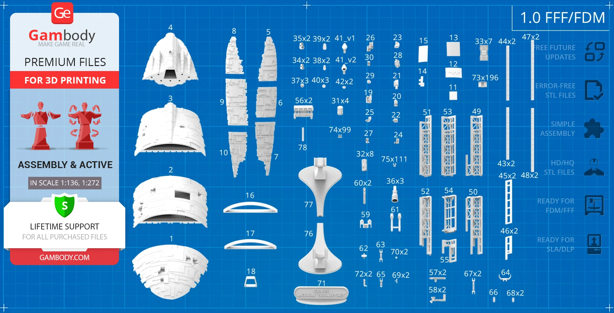
FFF/FDM
Assembly method
Connectors
Features
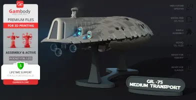
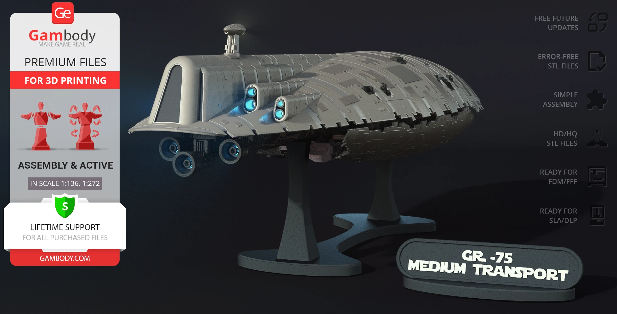
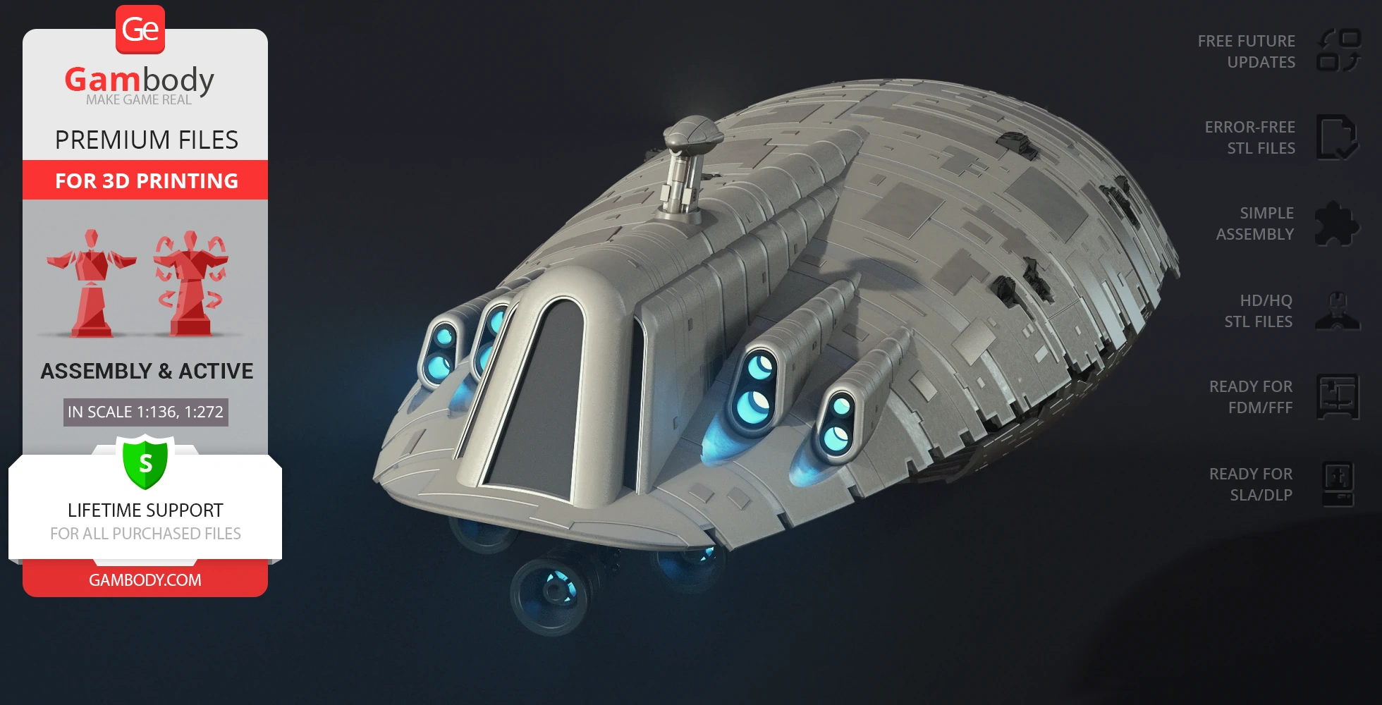
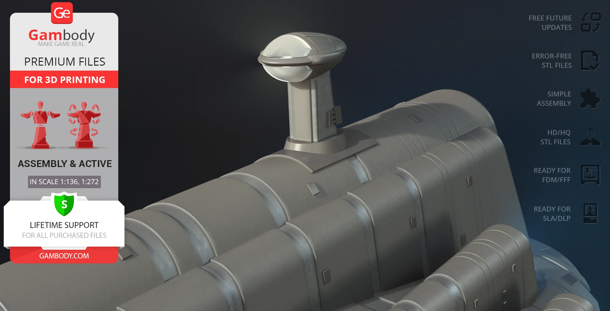
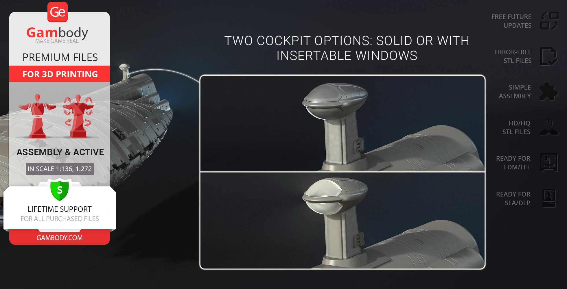
Includes two cockpit options: solid and with insertable window parts that can be printed with transparent filament;
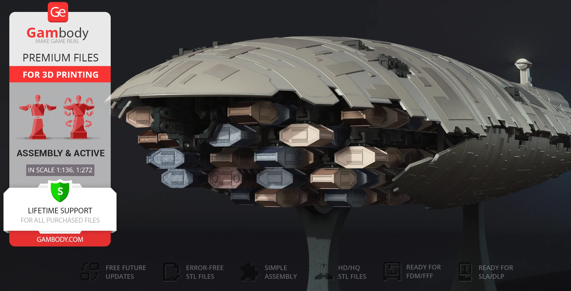
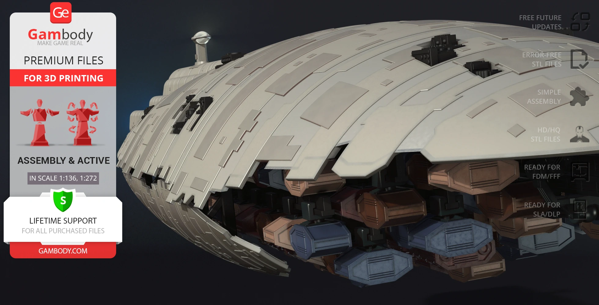
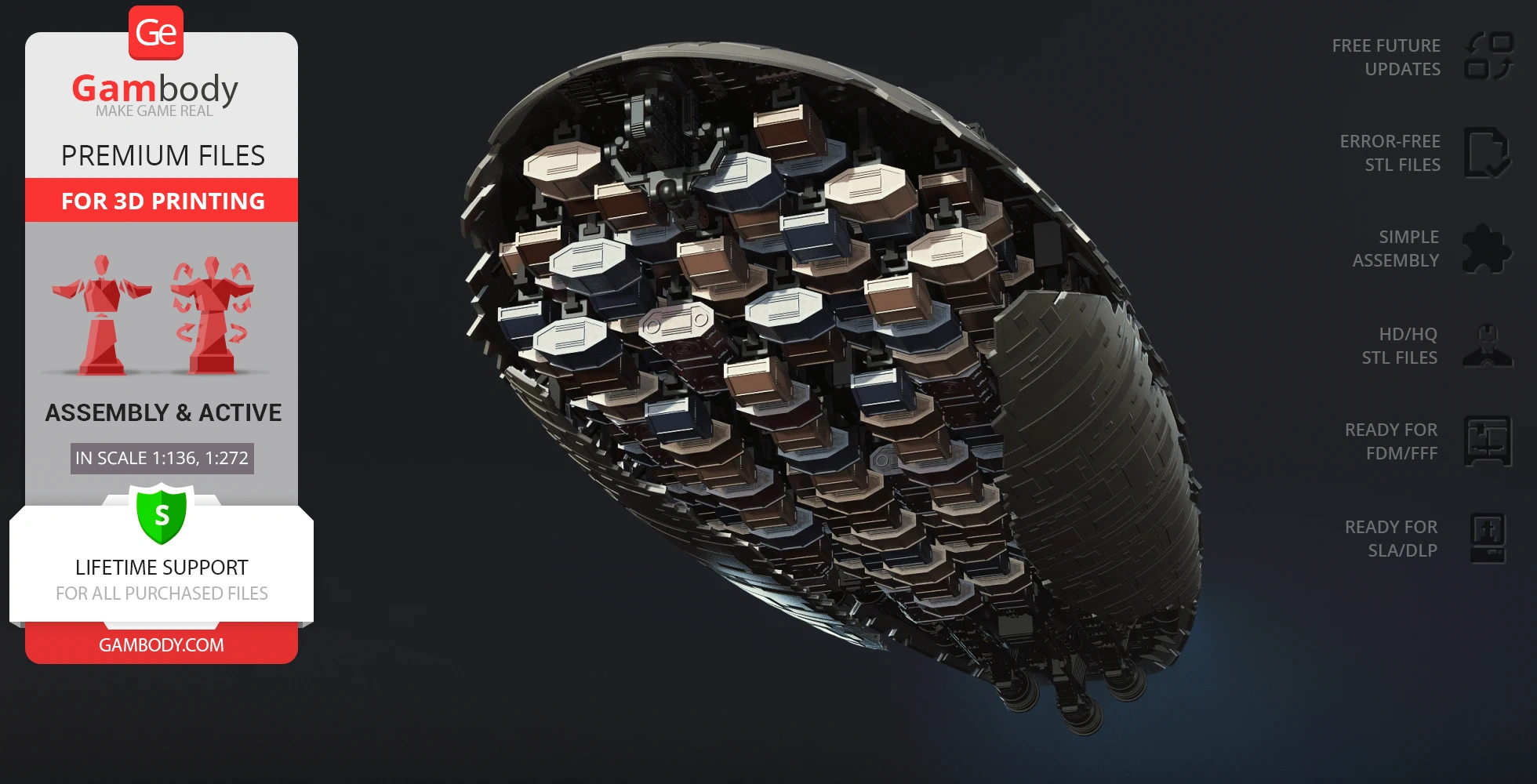
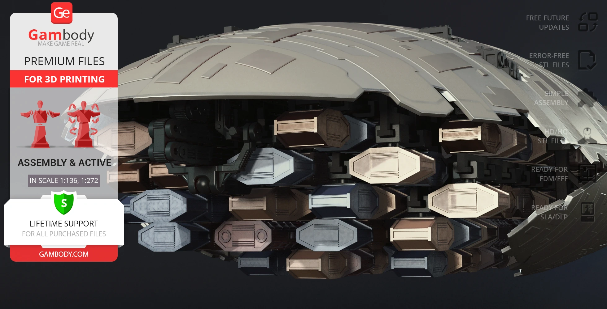
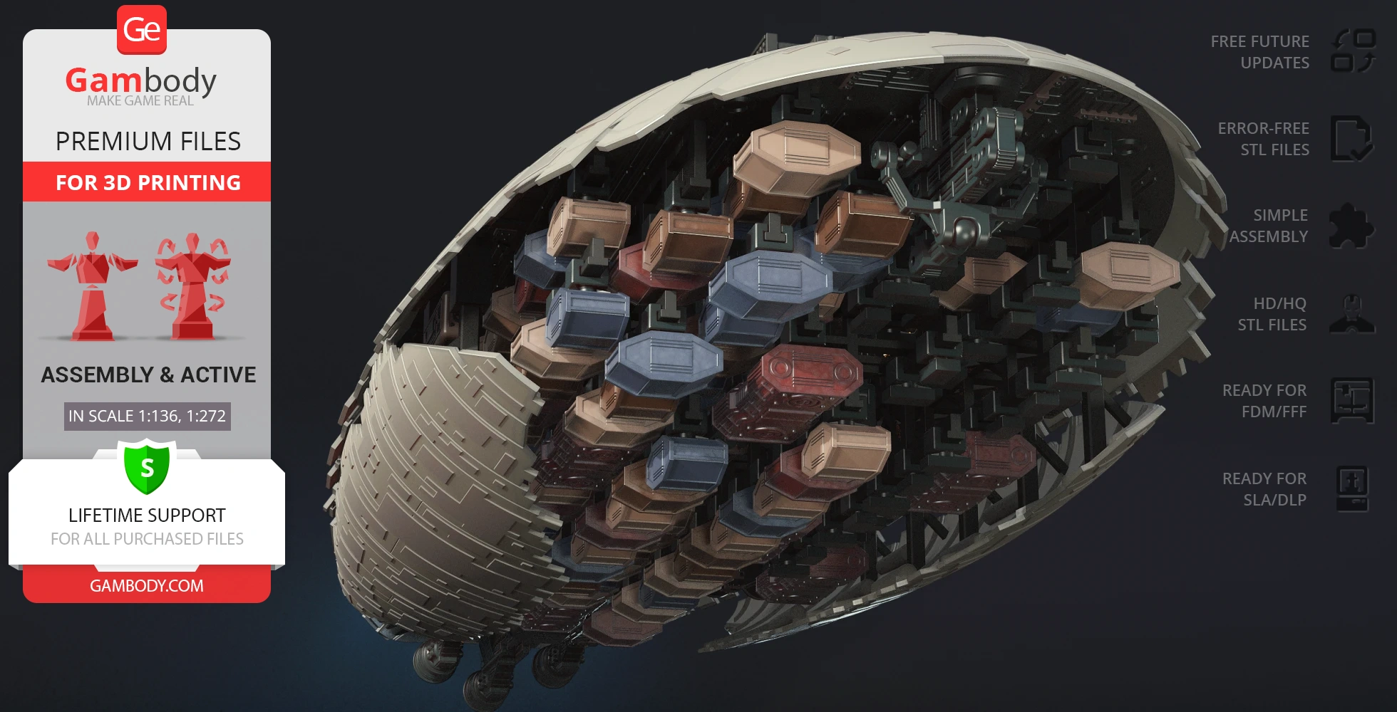
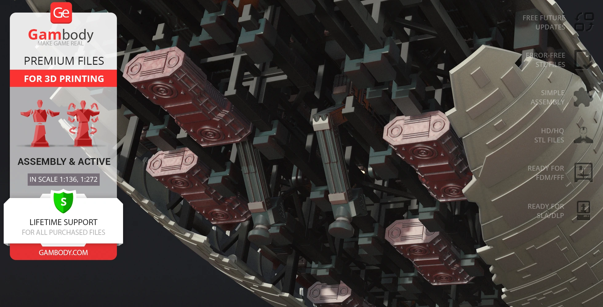
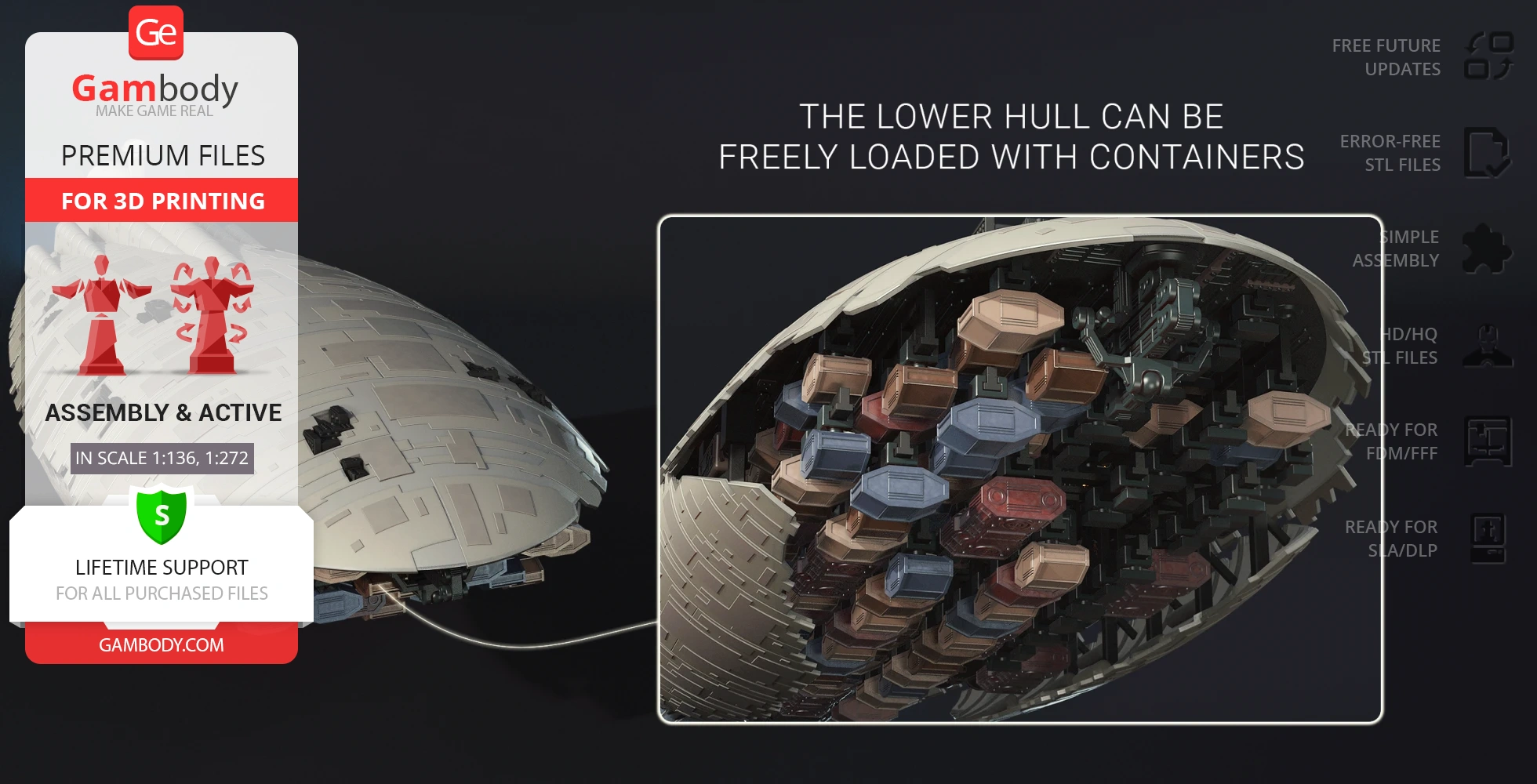
The lower hull is designed to be loaded with three container types;
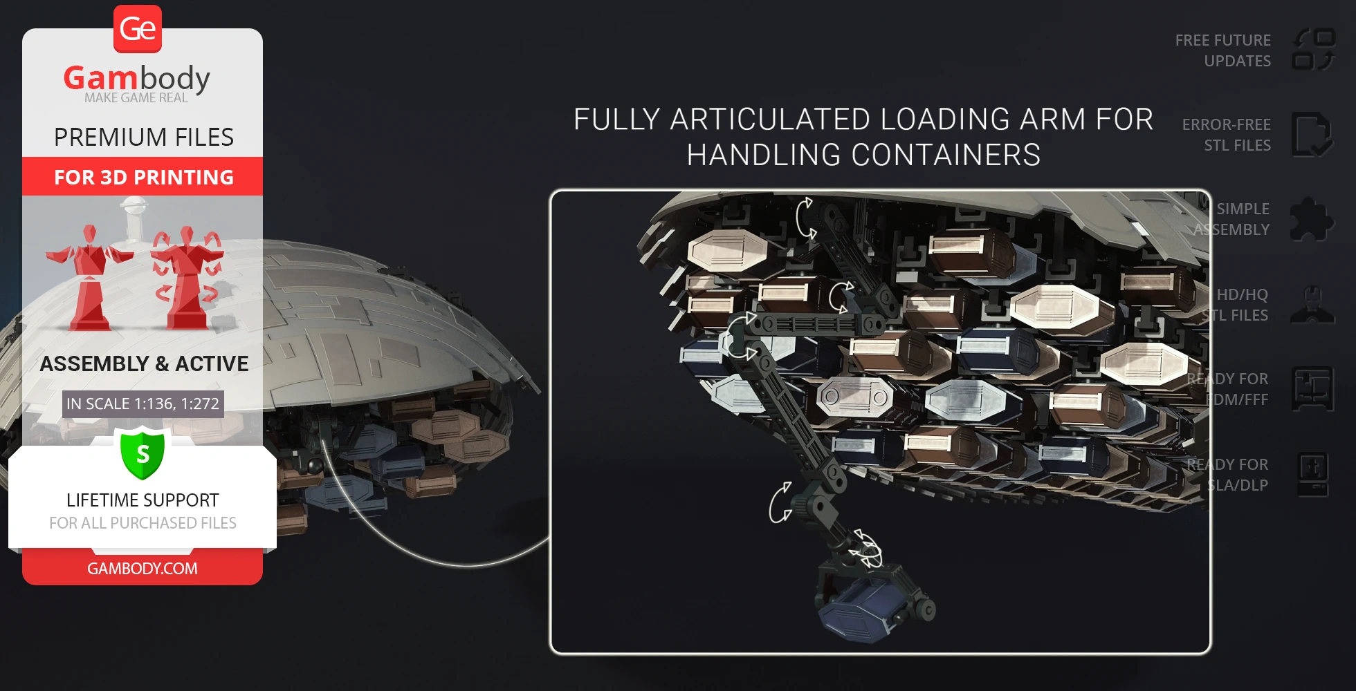
Features a fully articulated loading arm;
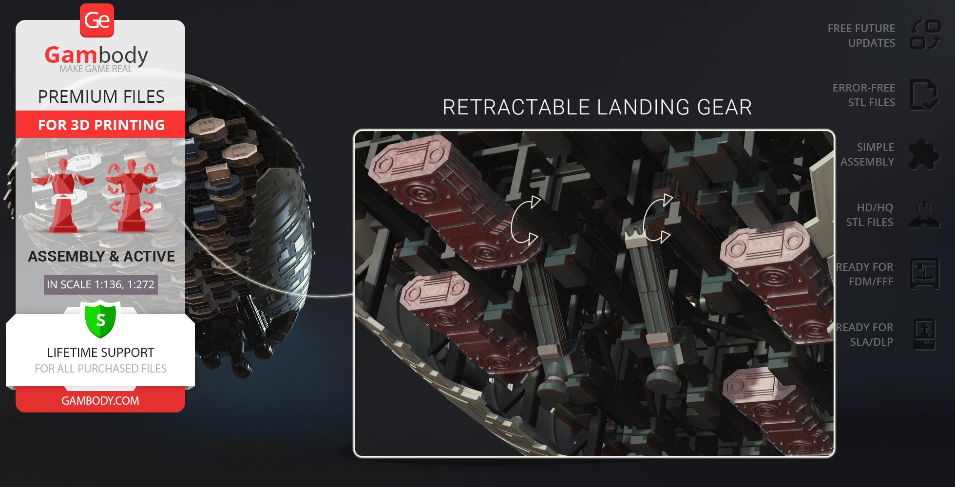
Comes with a retractable landing gear;
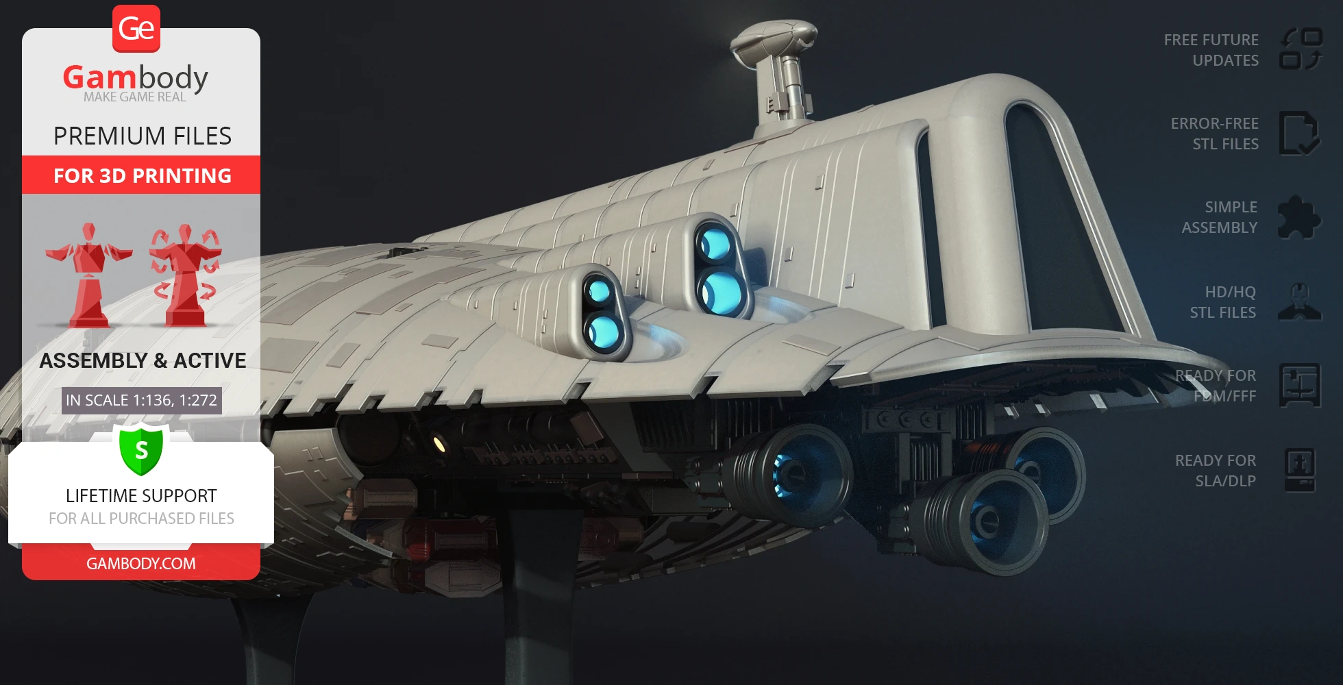
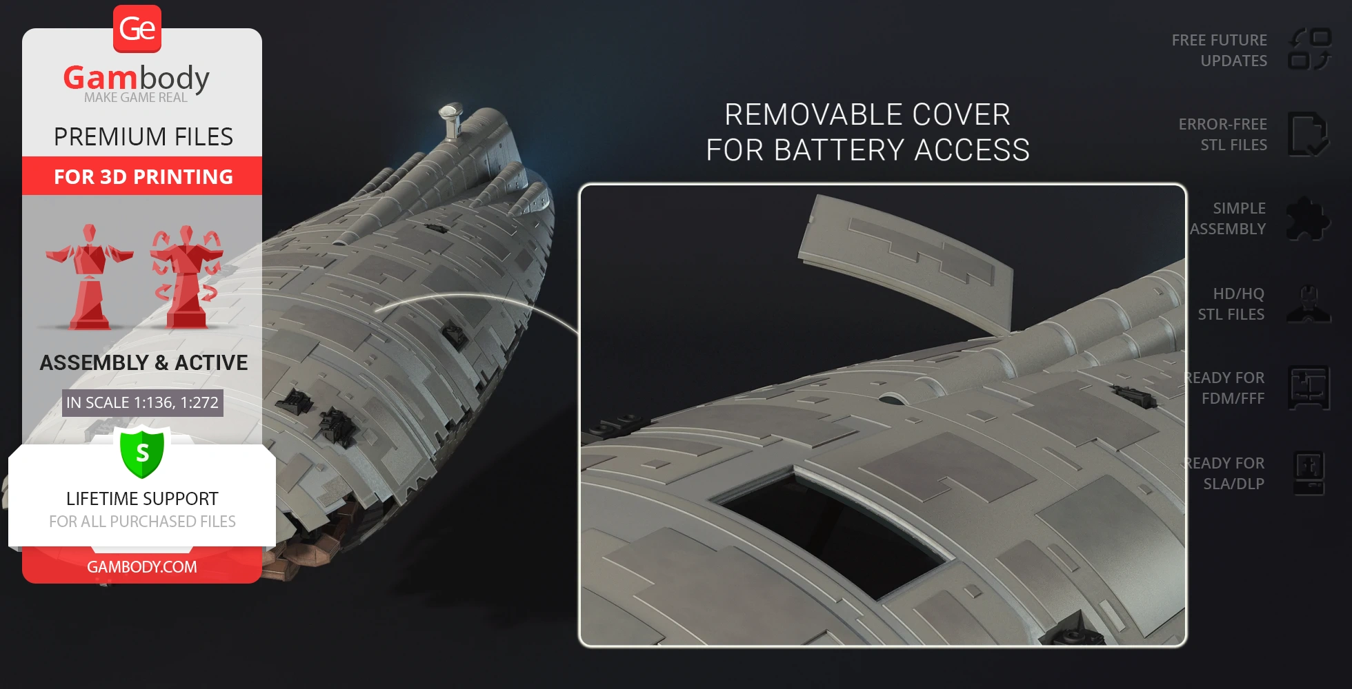
Features a removable top cover for battery access, allowing for optional LED installation;
The assembly parts are connected using specially designed integrated connectors that fit securely into the corresponding slots;
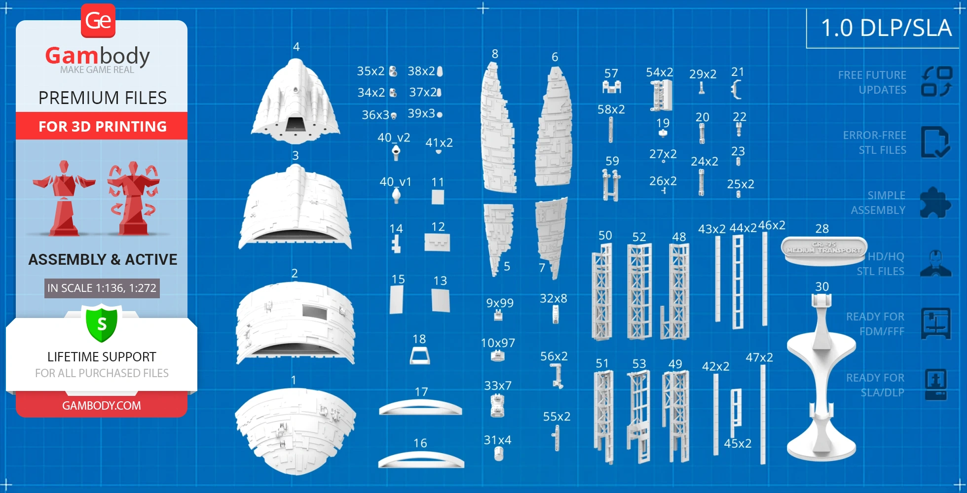
DLP/SLA
Eco parts
Assembly method
Connectors
Features
Includes two cockpit options: solid and with insertable window parts that can be printed with transparent filament;
The lower hull is designed to be loaded with three container types;
Features a fully articulated loading arm;
Comes with a retractable landing gear;
Features a removable top cover for battery access, allowing for optional LED installation;
The assembly parts are connected using specially designed integrated connectors that fit securely into the corresponding slots. Optionally, for added strength and rigidity, the static connections can be glued together;
Additional details
Part of diorama
No
Special pack included
No
You can get the STL files of GR-75 Medium Transport for 3D printing immediately after the purchase! Just click the green Buy button in the top-right corner of the model’s page. You can pay with PayPal or your credit card.
Watch the tutorial on how to assemble the 3D printed GR-75 Medium Transport Model from the provided 3D print files on Gambody YouTube channel.
Also, you may like other Spacecraft 3D Print Models.
________
FAQ:
This 3D model comes with StereoLithography (.STL) files optimized for 3D printing. You'll get digital files, not a physical product
Before printing, take a look at Printing Details for recommended settings and tips to achieve better results.
GR-75 Medium Transport 3D Printer Files | Assembly + Action includes 2 version(s) for the supported 3D printer type(s): FFF/FDM, DLP/SLA. Files are available for download after purchase.
See the Description and Specifications sections for more details about this model.
3D model history
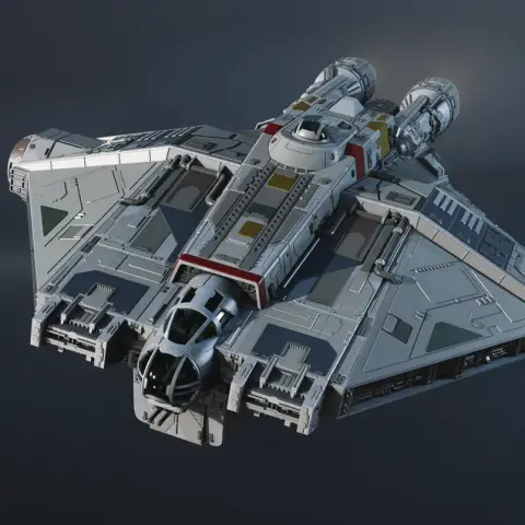
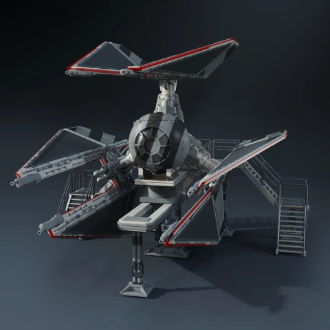
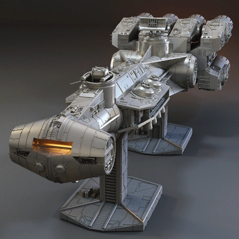
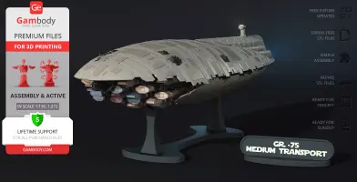
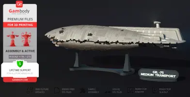
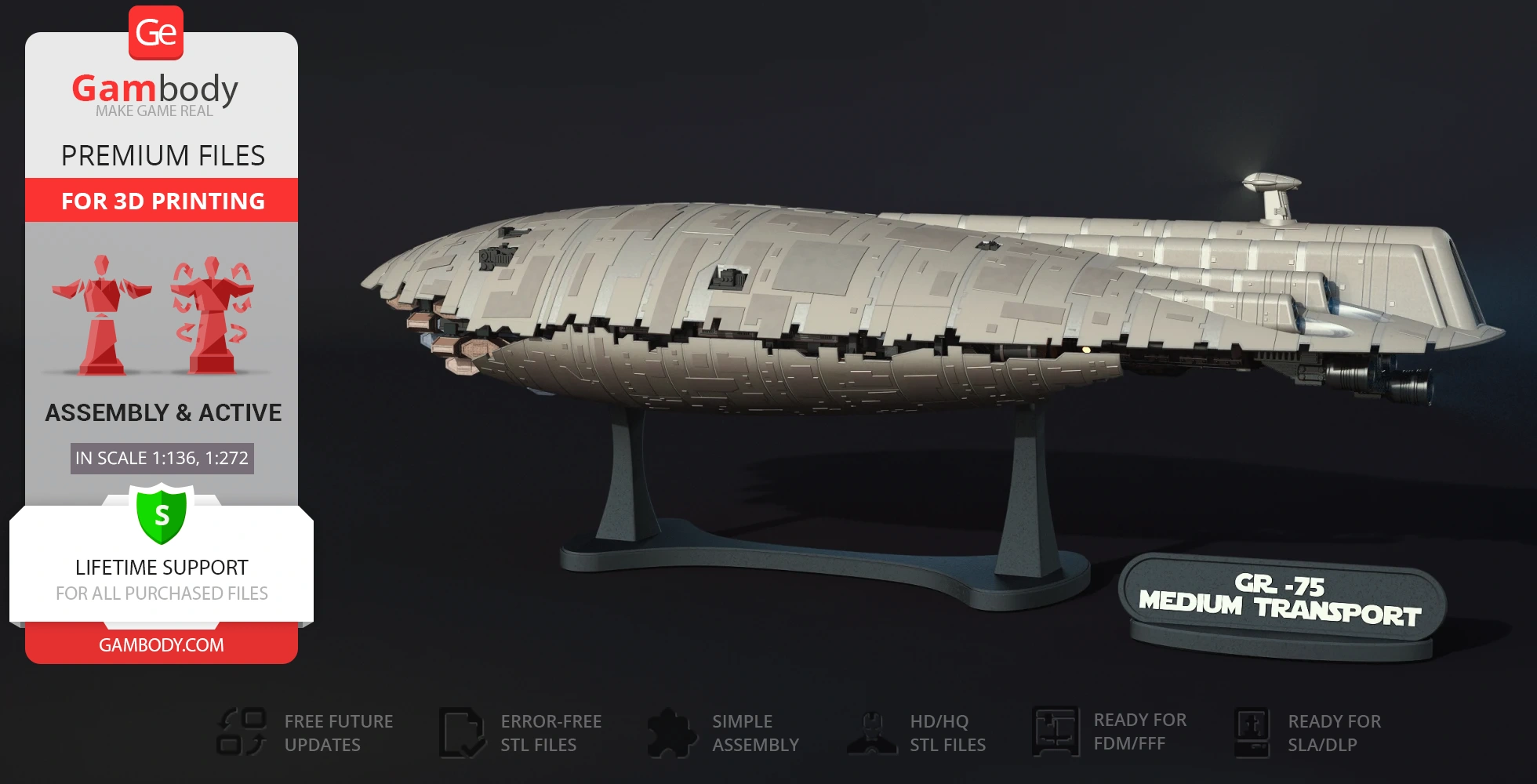
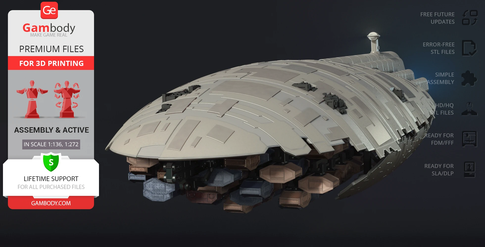
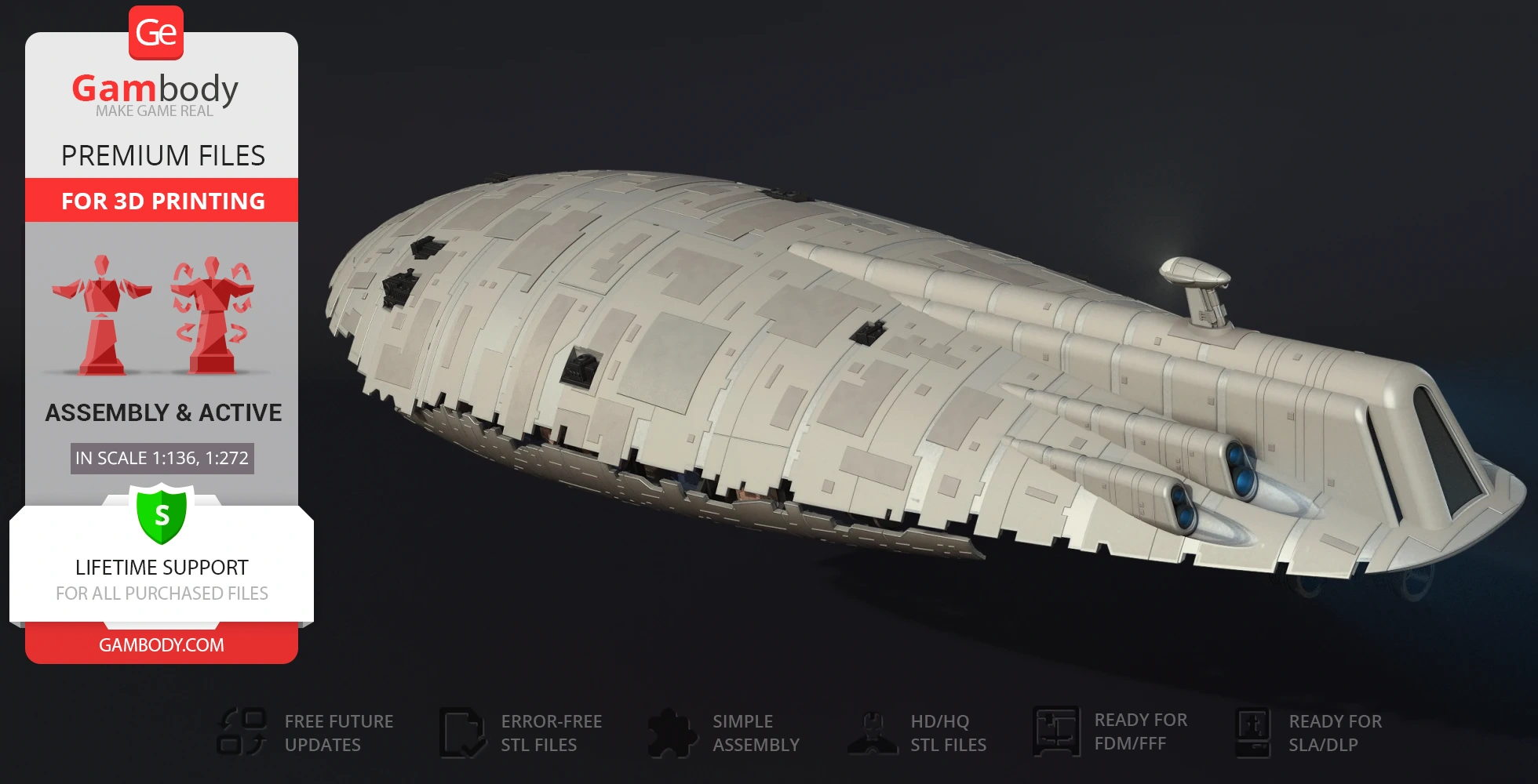
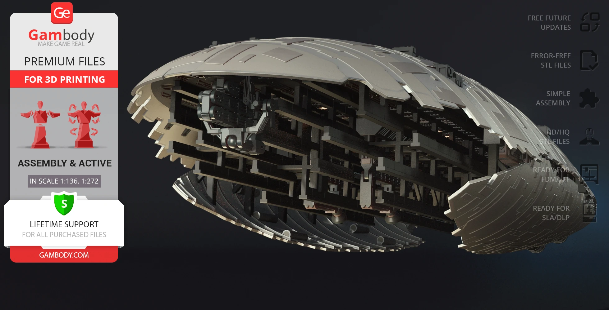
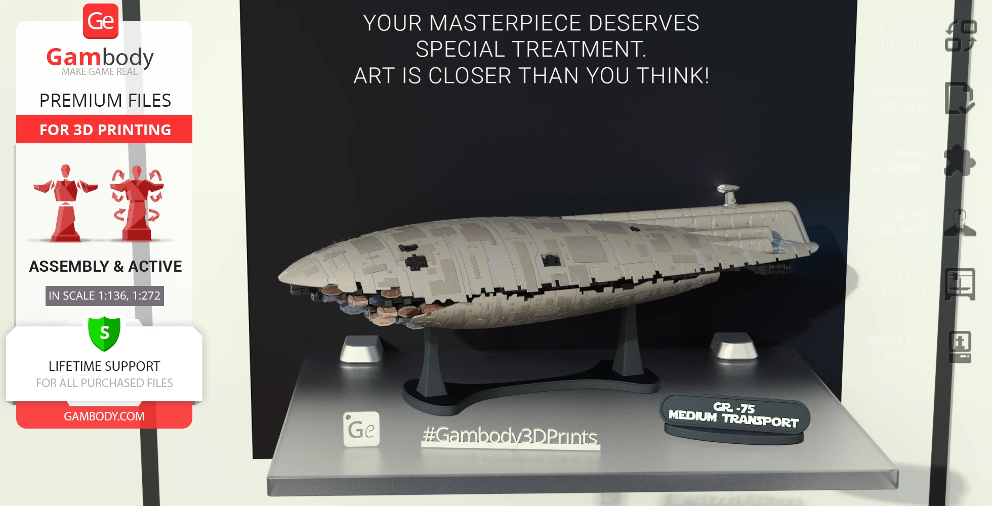
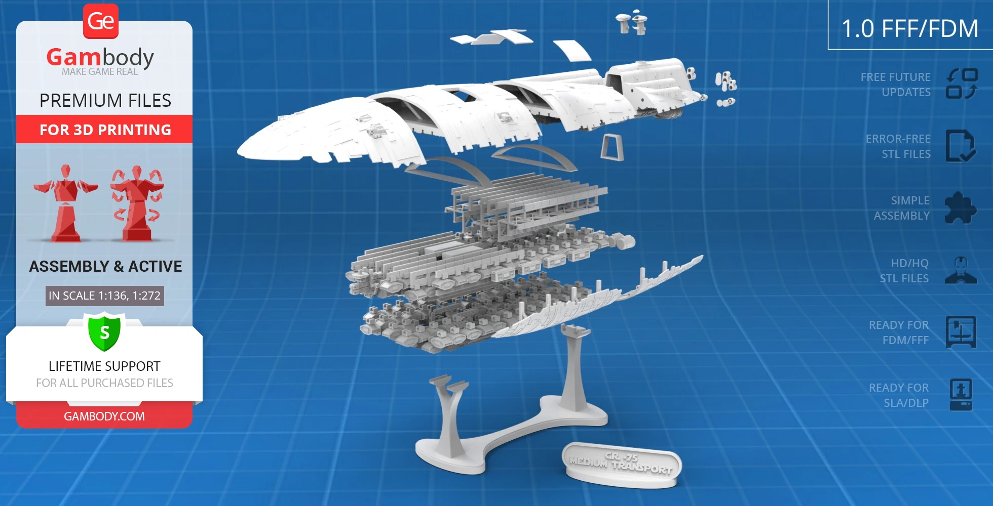
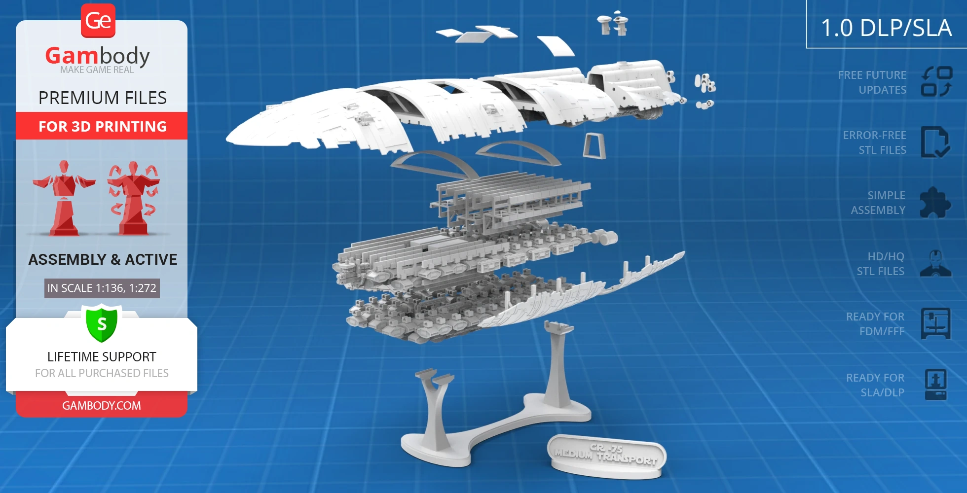
In the Star Wars universe, not all heroes fire lasers. The GR-75 Medium Transport, better known as the Rebel transport ship, quietly carried soldiers, supplies, and hope itself. With its clamshell hull and exposed cargo pods, this spaceship wasn't flashy, but it earned an iconic place in the fleet. From Hoth to Endor, this versatile spacecraft proved that survival often matters more than speed or weapons in sci-fi history.
The GR-75 3D model captures that enduring spirit in incredible detail. This sci-fi transport ship comes with two cockpit options, a fully articulated loading arm, and a lower hull designed to be freely packed with three container types. Retractable landing gear, LED-ready engines, and a removable top cover make this Star Wars 3D print as functional as it is cinematic. A standout among movie 3D models and 3D printed spacecraft, it's a tribute to the unassuming starship that helped carry the Rebellion forward.
3D printing model features
Model-specific features:
- Inspired by the Star Wars universe, this GR-75 Medium Transport 3D print model captures the spirit of the Rebellion's most reliable workhorse;
- Comes with two cockpit options: a solid piece and a version with separate, insertable window parts;
- Features a fully articulated loading arm for handling containers;
- The lower hull is designed to be freely loaded with three types of containers;
- Includes a retractable landing gear for dynamic display;
- The model is ready for optional LED lighting with a removable top cover for easy access to the battery compartment.
Printing & assembly details:
- Provided as error-free STL files compatible with most 3D printers;
- Optimized part division minimizes support material and ensures smooth surface detail;
- The assembly parts in the FFF/FDM version come in the recommended print orientations for easy bed placement;
- Assembly manual in PDF and video formats is included for both FFF/FDM and DLP/SLA versions;
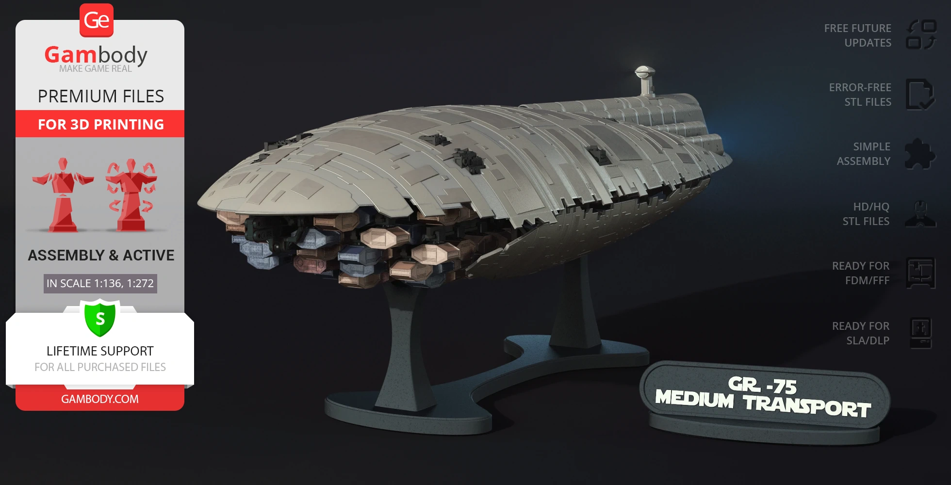
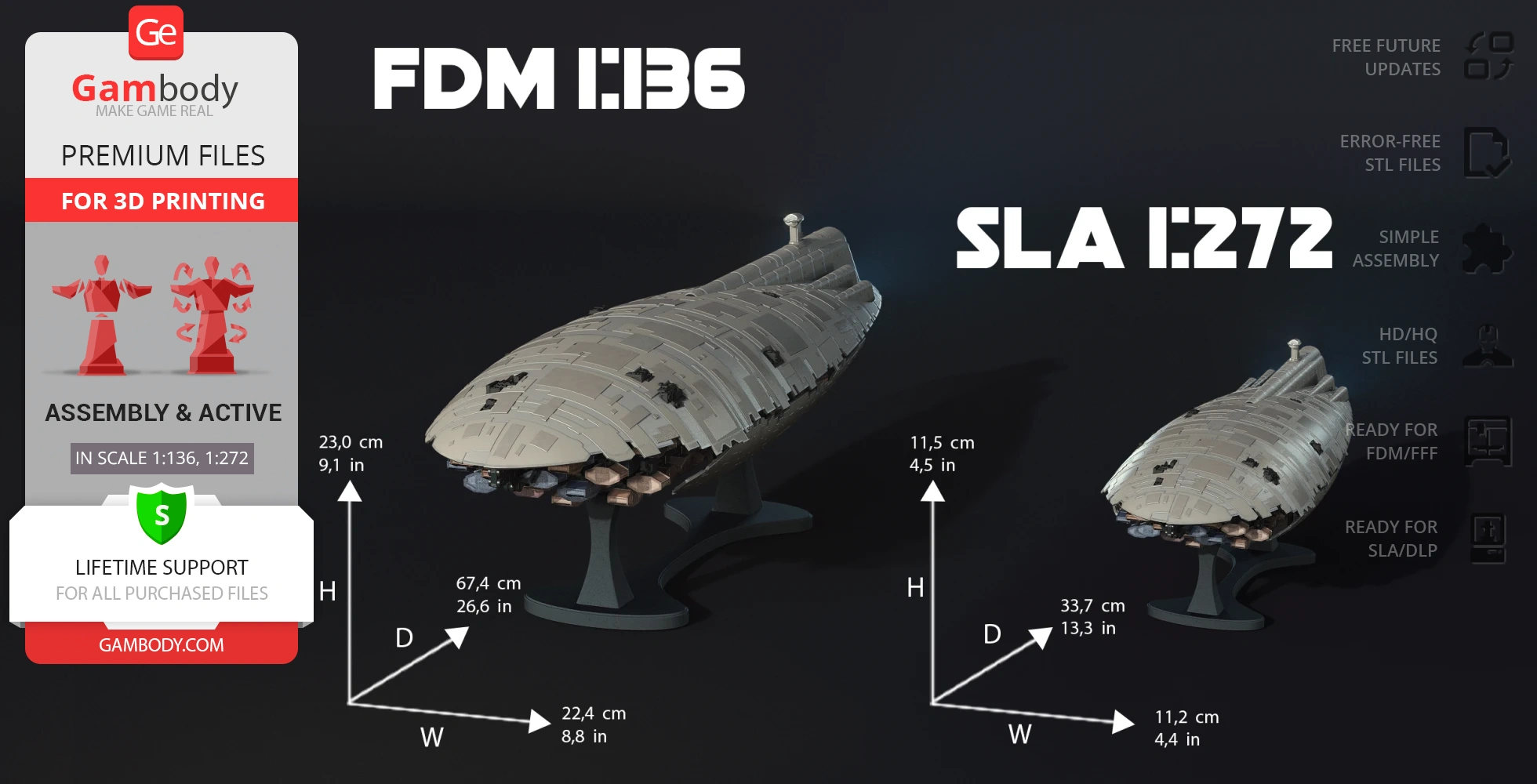
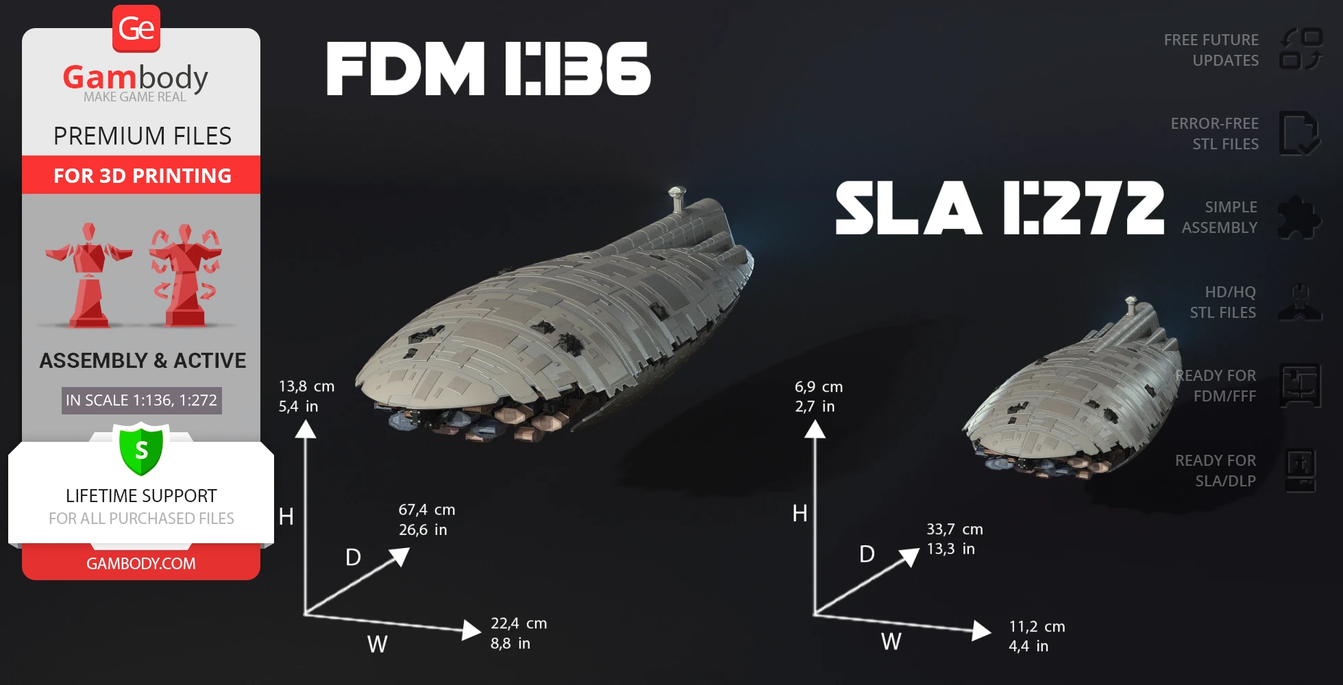
- The model is available in recommended scales of 1:136 for the FFF/FDM version and 1:272 for the DLP/SLA version, based on the length of the GR-75 Medium Transport.
What will you get after purchase?
- 2 versions of GR-75 Medium Transport STL files for FFF/FDM and DLP/SLA — files for all versions are available for download after the purchase;
- STL files of high-poly GR-75 Medium Transport for 3D printing consist of 139 files;
- Sizes for:
- FFF/FDM: 224 mm wide, 230 mm high, 674 mm deep;
- DLP/SLA: 112 mm wide, 115 mm high, 337 mm deep;
- Assembly Manual for 1.0 FFF/FDM and 1.0 DLP/SLA versions in PDF and video formats;
- Detailed settings that we provide as a recommendation for Bambu Studio, Cura, Orca Slicer, PrusaSlicer, Simplify3D, and Slic3r for the best print;
- Full technical support from the Gambody Support Team.
Average customer rating (5 reviews)
4.4
Ratings breakdown
Click a star rating to filter reviews
Overall experience
Level of detail in the model
4.8
Model cut quality and assembly guide
4.5
Clarity and accuracy of the model page
4.6
Level of detail in the model
5
Model cut quality and assembly guide
3.6
Clarity and accuracy of the model page
4
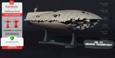
The GR-75 Medium Transport was engineered to support two display configurations. It can be mounted on the included base, or positioned directly on its four deployable support struts. These can be extended for a grounded presentation or folded away, giving you flexibility in how you integrate it into your collection layout.
We’d also be very grateful if you could share a few specifics at support@gambody.com about which parts of the guide felt unclear. Your input helps us improve the documentation and make the building process as smooth and intuitive as possible for everyone.
If any questions come up as you complete your setup, please feel free to reach out – we’re always happy to assist.
Level of detail in the model
4
Model cut quality and assembly guide
4
Clarity and accuracy of the model page
4
Thank you for your feedback on the GR-75 Medium Transport model! We appreciate you taking the time to let us know that some of the manipulator parts could be split better for optimal printing. We are always looking for ways to improve our file preparation. Could you please send more details about the parts you are referring to and how you would ideally like them to be cut to our dedicated Support Team at support@gambody.com?
Your input is invaluable and will be immediately forwarded to our Moderation Team for analysis and consideration in future updates to the model!
Level of detail in the model
5
Model cut quality and assembly guide
5
Clarity and accuracy of the model page
5
Level of detail in the model
5
Model cut quality and assembly guide
5
Clarity and accuracy of the model page
5
Level of detail in the model
5
Model cut quality and assembly guide
5
Clarity and accuracy of the model page
5
Below you'll find detailed slicing settings for Bambu Studio 2.0+, Orca Slicer 2.0+, UltiMaker Cura 5.0+, PrusaSlicer 2.0+, Slic3r 1.3+, Simplify3D 5.0+ to help you get the best results when printing this model. These settings are optimized specifically for this 3D model, but please note they may need slight adjustments depending on your printer or filament. When in doubt, refer to your printer's user manual.
To avoid printing issues and achieve the best quality, we highly recommend applying the following settings:
For better quality use 0.12 mm layer height, for fast printing use 0.2 mm layer height. For pins and the Ge connectors, use 0.2 layer height.
120-150% of your Layer Height
But you can paint the seam if you want.
You have to calibrate this parameter
You have to calibrate this parameter
You have to calibrate this parameter
For pins and power elements of the structure, such as the vehicle frame, use 3 loop
Disabled for vehicles and enabled for characters
For 0,2 Layer Height
The parameters in this tab vary greatly, it all depends on the quality of your printer. For example, if you have a classic Ender3, stick to the minimum parameters, but if you have a newer printer, for example Anycubic cobra 3 v2, you can select the maximum recommended values
Settings for advanced users, change these parameters only if you have sufficient 3D printing expertise
Enable this parameter if your model requires supports
We also recommend placing and removing supports manually in some places using special button
1-2 loops for more thick support
Top Z distance = 1-1.3 layer Height. If the supports are hard to remove, try increasing this setting by 0.1-0,4 mm
Bottom Z distance = 1-1.3 layer Height. If the supports are hard to remove, try increasing this setting by 0.1-0,4 mm
You have to calibrate this parameter which one is better for your filament
Increase this parameter if the supports are hard to remove from walls
For PLA and PETG filament types
5-8 mm is optional for small prints that have bad adhesion to the build plate
You have to calibrate this parameter
Read the description on your filament roll
Read the description on your filament roll and increase this parameter for fast printers
Read the description on your filament roll and increase this parameter for fast printers
For better quality use 0.12 mm layer height, for fast printing use 0.2 mm layer height. For pins and the Ge connectors, use 0.2 layer height.
120-150% of your Layer Height
But you can paint the seam if you want.
0.01-0.05 You have to calibrate this parameter
0.01-0.05 You have to calibrate this parameter
0.1-0.2 You have to calibrate this parameter
For pins and power elements of the structure, such as the vehicle frame, use 3 loop
Disabled for vehicles and ships, enabled for characters
For 0,2 Layer Height
For 0,2 Layer Height
The parameters in this tab vary greatly, it all depends on the quality of your printer. For example, if you have a classic Ender3, stick to the minimum parameters, but if you have a newer printer, for example, Anycubic Kobra 3 Or Bambulab A1, you can select the maximum recommended values.
Settings for advanced users, change these parameters only if you have sufficient 3D printing expertise
Enable this parameter if your model requires supports
We also recommend placing and removing supports manually in some places using special button
Top Z distance = 1-1.3 layer Height. If the supports are hard to remove, try increasing this setting by 0.1-0,4 mm
Bottom Z distance = 1-1.3 layer Height. If the supports are hard to remove, try increasing this setting by 0.1-0,4 mm
Increase this parameter if the supports are hard to remove from walls
For PLA and PETG filament types
5-8 mm is optional for small prints that have bad adhesion to the build plate
Read the description on your filament roll
Read the description on your filament roll and increase this parameter for fast printers
You have to calibrate this parameter
Read the description on your filament roll and increase this parameter for fast printers
Read the description on your filament roll
This field is filled in according to your printer specifications when you add it to the slicer.
You can add custom G-code here for the start and end of the print. However, be careful - this is for advanced users only!
You have to calibrate your printer using Ge retraction test models
Retraction Length: For direct-drive setups use 0.5 mm to 2.5 mm; for Bowden extruders use 5 to 7 mm
This is how fast the filament is pulled back—40-60 mm/s for direct drive and 30-50 mm/s for Bowden setups.
You have to calibrate this parameter: Reduce it until the printer starts to hit the parts with the nozzle during printing, then increase it by 0.2.
For better quality use 0.12 mm layer height, for fast printing use 0.2 mm layer height. For pins and the Ge connectors, use 0.2 layer height.
120-150% of your Layer Height
To increase the strength of the print parts, use wall line count: 3
For pins and connectors use 50% Infill
These parameters are for standard PLA plastic. If you are using a different type of plastic, check the printing temperature recommended by the manufacturer. Also, read the description on your filament spool. For fast printers, add +30 °C to the current parameters.
The parameters in this tab vary greatly, it all depends on the quality of your printer. For example, if you have a classic Ender3, stick to the minimum parameters, but if you have a newer printer, for example Anycubic cobra 3 v3, you can select the maximum recommended values
Settings for advanced users, change these parameters only if you have sufficient 3D printing expertise.
You need to calibrate this parameter using Gambody test models. These values are average values for a Direct Drive extruder; for a Bowden extruder, the values should be increased.
You need to calibrate this parameter using Gambody test models. These values are average values for a Direct Drive extruder; for a Bowden extruder, the values should be increased.
Use this value other than 0 if your nozzle catches on the internal infill during travel moves. Try to keep this value as low as possible in height.
Use normal supports to support large, straight surfaces (most mechanical or technical parts).
You have to calibrate this parameter according to the capabilities of your printer and your filament, using a Gambody test models.
Use 1 instead of 0 if your supports are thin and tall. They will be harder to remove, but much stronger.
Top Z distance = 1-1.3 layer Height. If the supports are hard to remove, try increasing this setting by 0.1-0,4 mm
Increase this parameter if the supports are hard to remove from walls
Use tree supports to support complex objects, such as characters.
You have to calibrate this parameter according to the capabilities of your printer and your filament, using a Gambody test models.
Top Z distance = 1-1.3 layer Height. If the supports are hard to remove, try increasing this setting by 0.1-0,4 mm
Increase this parameter if the supports are hard to remove from walls
Use a skirt for all parts when printing on outdated printers.
Use a brim when printing thin but tall parts, as well as parts with a small bed adhesion area.
For better quality use 0.12 mm layer height, for fast printing use 0.2 mm layer height. For pins and the Ge connectors, use 0.2 layer height.
120-150% of your Layer Height
for 0.2 Layer Height
But you can paint the seam if you want.
(for PLA and PETG)
(5-8 mm is optional for small prints that have bad adhesion to the build plate)
Enable this parameter if your model requires supports
(45-50 degree)You have to calibrate this parameter according to the capabilities of your printer
and your filament, using a Gambody test models.
Top contact Z distance = 1-1.3 layer Height. If the supports are hard to remove, try
increasing this setting by 0.1-0,4 mm
Top contact Z distance = 1-1.3 layer Height. If the supports are hard to remove, try
increasing this setting by 0.1-0,4 mm
Increase this parameter if the supports are hard to remove from walls
The parameters in this tab vary greatly, it all depends on the quality of your printer. For example, if you have a classic Ender3, stick to the minimum parameters, but if you have a newer printer, for example Anycubic cobra 3 v3, you can select the maximum recommended values
Settings for advanced users, change these parameters only if you have sufficient 3D printing expertise. Use the minimum value for outdated printers without acceleration calibration, and the maximum value for modern printers if you need it.
These settings only work for 3D printers with multiple extruders
You can try setting all parameters in this section, except the First layer, to values between 0.75% of your nozzle diameter and 1.25% of your nozzle diameter. Adjusting them will help you work out the optimal parameters for the best quality for your print. As for the First layer, you can set it to 150% of the diameter of your nozzle for better adhesion to the build plate (for a nozzle with a diameter of 0.4 mm, the First layer extrusion width can be from 0.3 mm to 0.5 mm)
For better printing quality you have to calibrate this parameter using Gambody test model.
Check your filament manufacturer's temperature recommendations on the spool.
Cooling parameters depends on the material you use for printing.
*for PLA
For better quality use 0.12 mm layer height, for fast printing use 0.2 mm layer height. For pins and the Ge connectors, use 0.2 layer height.
120-150% of your Layer Height
For 0.12 Layer Height
For 0.12 Layer Height
For pins and connectors use 50% Infill
Use skirt for outdated 3d printers
(5-8 mm is optional for small prints that have bad adhesion to the build plate)
Enable this parameter if your model requires supports
(45-60 degree)You have to calibrate this parameter according to the capabilities of your printer and your filament, using a Gambody test models
Contact Z distance = 1-1.3 layer Height. If the supports are hard to remove, try increasing this setting by 0.1-0,4 mm
The parameters in this tab vary greatly, it all depends on the quality of your printer. For example, if you have a classic Ender3, stick to the minimum parameters, but if you have a newer printer, for example Anycubic cobra 3 v3, you can select the maximum recommended values
Settings for advanced users, change these parameters only if you have sufficient 3D printing expertise. Use the minimum value for outdated printers without acceleration calibration, and the maximum value for modern printers if you need it.
You have to calibrate this parameter from 0.9 to 1.1 according to the capabilities of your printer and your filament, using a Gambody test models.
Check your filament manufacturer's temperature recommendations on the spool.
Cooling parameters depends on the material you use for printing.
Calibrate this value if you need to reduce or improve the adhesion between the plastic and the heat bed
Your current nozzle diameter
You need to calibrate this parameter using Gambody test models. These values are average values for a Direct Drive extruder; for a Bowden extruder, the values should be increased.
Your current nozzle diameter
You have to calibrate this parameter using Gambody test models.
You need to calibrate this parameter using Gambody test models. These values are average values for a Direct Drive extruder; for a Bowden extruder, the values should be increased.
For better quality use 0.12 mm layer height, for fast printing use 0.2 mm layer height. For pins and the Ge connectors, use 0.2 layer height.
For 0,2 Layer Height
For 0,2 Layer Height
To increase the strength of the print parts, use Outline Perimeters: 3
You can enable this parameter to print rounded or spherical models, as well as character models.
Use this option only if your parts are too tight. but better calibrate your printer extrusion
Use this option only if your parts are too tight. but better calibrate your printer extrusion
Use 2 and more if you want to create skirt instead brim
1-2 for skirt and 10-20 for brim
Use for wipe nozzle if you need
Use For ABS filament
For pins and connectors use 50% Infill
Top Z distance = 1-1.3 layer Height. If the supports are hard to remove, try increasing this setting by 0.1-0,4 mm
Calibrate your filament and detect optimal temperature for it
Average temperature for PLA filament
The parameters in this tab vary greatly, it all depends on the quality of your printer. For example, if you have a classic Ender3, stick to the minimum parameters, but if you have a newer printer, for example Anycubic cobra 3 v3, you can select the maximum recommended values
Settings for advanced users, change these parameters only if you have sufficient 3D printing expertise.
DLP/SLA
Includes two cockpit options: solid and with insertable window parts that can be printed with transparent filament;
The lower hull is designed to be loaded with three container types;
Features a fully articulated loading arm;
Comes with a retractable landing gear;
Features a removable top cover for battery access, allowing for optional LED installation;
The assembly parts are connected using specially designed integrated connectors that fit securely into the corresponding slots. Optionally, for added strength and rigidity, the static connections can be glued together;
FFF/FDM
Includes two cockpit options: solid and with insertable window parts that can be printed with transparent filament;
The lower hull is designed to be loaded with three container types;
Features a fully articulated loading arm;
Comes with a retractable landing gear;
Features a removable top cover for battery access, allowing for optional LED installation;
The assembly parts are connected using specially designed integrated connectors that fit securely into the corresponding slots;