Specifications
Source Files
Description
Update History
Printing Details
Feedbacks (0)
Comments
Specifications
Source Files
Description
Update History
Printing Details
Feedbacks (0)
Comments
Ghost VCX-100 3D Printer Files | Assembly
Specifications

Files

3D model format

Stereolithography (.stl)

Total files

174
Information
The total number of 3D model files available across all versions and updates of this model, including variants optimized for different types of 3D printers.

License

Personal use

Mesh error check

Netfabb

Support

Lifetime support from Gambody team

Update requests

Available to verified buyers

Model complexity

Advanced
Information

Advanced: may require tuning print settings or support placement, plus precise fitting, gluing, or sanding.

Assembly guide

PDF manual, Video

Model versions

1.0 Initial

FFF/FDM

Files

101

Parts

99

Scale

1:68

Printed model size

Height: 7.44” (189 mm) • Width: 21.06” (535 mm) • Depth: 25.94” (659 mm)

Printed base size

Height: 3.15” (80 mm) • Width: 7.09” (180 mm) • Depth: 7.13” (181 mm)

Assembly method

Connectors, Glue

Features

Includes highly detailed interior with removable covers; Features articulated top and chin turrets; Openable front hangar with an extendable ramp; Side airlocks in open and closed variants; Includes both deployed and retracted landing gear for display on a platform or gear; Hollowed-out hull with optional LED-ready side panels; The assembly parts are connected using specially designed integrated connectors that fit securely into the corresponding slots. Optionally, for added strength and rigidity, the static connections can be glued together.

DLP/SLA

Files

73

Parts

71

Eco parts

0
Information
Number of hollow parts to reduce resin usage when printing on DLP/SLA printers.

Scale

1:136

Printed model size

Height: 3.74” (95 mm) • Width: 10.51” (267 mm) • Depth: 12.99” (330 mm)

Printed base size

Height: 1.57” (40 mm) • Width: 3.54” (90 mm) • Depth: 3.58” (91 mm)

Assembly method

Connectors, Glue

Features

Includes highly detailed interior with removable covers; Static top and chin turrets; Openable front hangar doors; Side airlocks in open and closed variants; Includes both deployed and retracted landing gear for display on a platform or gear; Hollowed-out hull with optional LED-ready side panels; The assembly parts are connected using specially designed integrated connectors that fit securely into the corresponding slots. Optionally, for added strength and rigidity, the static connections can be glued together.

Additional details

Part of diorama

No

Special pack included

No

You will get instant access to the STL files of Ghost VCX-100 3D Printer Files | Assembly after completing your purchase. Simply add the model to your cart and check out using PayPal, credit or debit card, Apple Pay, Google Pay, Alipay, or other available payment methods.

Watch the assembly video for Ghost VCX-100 3D Printer Files | Assembly, and explore more tutorials, behind-the-scenes content, 3D printing timelapses, and painting guides on the official Gambody YouTube channel.

Source Files

This 3D model comes with StereoLithography (.STL) files optimized for 3D printing. You'll get digital files, not a physical product

Important

Before printing, take a look at Printing Details for recommended settings and tips to achieve better results.

Ghost VCX-100 3D Printer Files | Assembly includes 2 version(s) for the supported 3D printer type(s): FFF/FDM, DLP/SLA. Files are available for download after purchase.
See the Description and Specifications sections for more details about this model.

--Select printer type--
View update history
--Select model version--
_01_bodyPart_a_FrontMid_FDM (repaired).stl
Size: 168.24 x 139.89 x 169.32 mm | 6.62 x 5.51 x 6.67 in File size: 11.05 mb Printing Time / Filament: 96 h 27 min / 65 m
_02_bodyPart_b_FrontL_FDM (repaired).stl
Size: 132.66 x 88.38 x 169.37 mm | 5.22 x 3.48 x 6.67 in File size: 3.96 mb Printing Time / Filament: 24 h 17 min / 12 m
_03_bodyPart_c_FrontR_FDM (repaired).stl
Size: 132.67 x 88.43 x 169.35 mm | 5.22 x 3.48 x 6.67 in File size: 3.95 mb Printing Time / Filament: 24 h 25 min / 12 m
_04_bodyPart_d_MidL_FDM (repaired).stl
Size: 134.14 x 175.89 x 179.21 mm | 5.28 x 6.92 x 7.06 in File size: 11.76 mb Printing Time / Filament: 97 h 55 min / 63 m
_05_bodyPart_e_Mid_FDM (repaired).stl
Size: 176.16 x 162.19 x 175.95 mm | 6.94 x 6.39 x 6.93 in File size: 15.06 mb Printing Time / Filament: 176 h 56 min / 126 m
_06_bodyPart_f_MidR_FDM (repaired).stl
Size: 134.14 x 175.9 x 179.21 mm | 5.28 x 6.93 x 7.06 in File size: 11.77 mb Printing Time / Filament: 96 h 42 min / 63 m
_07_bodyPart_g_RearL_FDM (repaired).stl
Size: 136.13 x 86.27 x 148.6 mm | 5.36 x 3.4 x 5.85 in File size: 5.76 mb Printing Time / Filament: 30 h 26 min / 18 m
_08_bodyPart_h_RearMid_FDM (repaired).stl
Size: 139.79 x 124.42 x 148.61 mm | 5.5 x 4.9 x 5.85 in File size: 9.25 mb Printing Time / Filament: 82 h 16 min / 61 m
_09_bodyPart_i_RearR_FDM (repaired).stl
Size: 135.84 x 86.18 x 148.62 mm | 5.35 x 3.39 x 5.85 in File size: 5.81 mb Printing Time / Filament: 30 h 45 min / 18 m
_10_bodyPin_X40_FDM (repaired).stl
Size: 20 x 10 x 5 mm | 0.79 x 0.39 x 0.2 in File size: 0.01 mb Printing Time / Filament: 9 min / <1 m
_11_bodySideCap_a_L_FDM (repaired).stl
Size: 187.71 x 20.07 x 67.59 mm | 7.39 x 0.79 x 2.66 in File size: 0.96 mb Printing Time / Filament: 8 h 50 min / 5 m
_12_bodySideCap_b_R_FDM (repaired).stl
Size: 187.71 x 20.06 x 67.59 mm | 7.39 x 0.79 x 2.66 in File size: 0.96 mb Printing Time / Filament: 9 h 1 min / 5 m
_13_V1_bodySideDoorClose_X2_FDM (repaired).stl
Size: 39.35 x 39.64 x 5.94 mm | 1.55 x 1.56 x 0.23 in File size: 0.98 mb Printing Time / Filament: 53 min / <1 m
_13_V2_bodySideDoorOpen_X2_FDM (repaired).stl
Size: 39.35 x 39.35 x 5.94 mm | 1.55 x 1.55 x 0.23 in File size: 1.06 mb Printing Time / Filament: 43 min / <1 m
_14_bodyCockpitPart_FDM (repaired).stl
Size: 72.24 x 74.54 x 58.24 mm | 2.84 x 2.93 x 2.29 in File size: 2.82 mb Printing Time / Filament: 6 h 51 min / 4 m
_15_bodyTopCap_a_FDM (repaired).stl
Size: 50.63 x 131 x 6.12 mm | 1.99 x 5.16 x 0.24 in File size: 0.35 mb Printing Time / Filament: 4 h 42 min / 2 m
_16_bodyTopCap_b_FDM (repaired).stl
Size: 47.73 x 48.66 x 18.72 mm | 1.88 x 1.92 x 0.74 in File size: 1.01 mb Printing Time / Filament: 2 h 29 min / 1 m
_17_bodyTopCap_c_FDM (repaired).stl
Size: 171.42 x 58.75 x 101.67 mm | 6.75 x 2.31 x 4 in File size: 6.21 mb Printing Time / Filament: 40 h 30 min / 24 m
_18_bodyTopCap_c_decorPlate_a_L_FDM (repaired).stl
Size: 20.3 x 23.06 x 5.98 mm | 0.8 x 0.91 x 0.24 in File size: 1.69 mb Printing Time / Filament: 20 min / <1 m
_19_bodyTopCap_c_decorPlate_b_R_FDM (repaired).stl
Size: 20.3 x 23.06 x 5.98 mm | 0.8 x 0.91 x 0.24 in File size: 1.69 mb Printing Time / Filament: 20 min / <1 m
_20_bodyTopCap_c_decorPlate_c_Top_FDM (repaired).stl
Size: 13.04 x 24.95 x 4.42 mm | 0.51 x 0.98 x 0.17 in File size: 0.93 mb Printing Time / Filament: 13 min / <1 m
_21_bodyTubeBot_X2_FDM (repaired).stl
Size: 15.31 x 104.33 x 8.56 mm | 0.6 x 4.11 x 0.34 in File size: 0.18 mb Printing Time / Filament: 44 min / <1 m
_22_cargoDoor_FDM (repaired).stl
Size: 37.53 x 3.25 x 31.2 mm | 1.48 x 0.13 x 1.23 in File size: 0.15 mb Printing Time / Filament: 37 min / <1 m
_23_rampPart_a_FDM (repaired).stl
Size: 39.98 x 17.25 x 39.95 mm | 1.57 x 0.68 x 1.57 in File size: 1.76 mb Printing Time / Filament: 2 h 14 min / 1 m
_24_rampPart_b_FDM (repaired).stl
Size: 37.39 x 26.91 x 3.08 mm | 1.47 x 1.06 x 0.12 in File size: 0.20 mb Printing Time / Filament: 29 min / <1 m
_25_cockpitPart_a_FDM (repaired).stl
Size: 54.7 x 35.59 x 35.68 mm | 2.15 x 1.4 x 1.4 in File size: 0.95 mb Printing Time / Filament: 2 h 46 min / 2 m
_26_cockpitPart_b_FDM (repaired).stl
Size: 62.33 x 32.44 x 41 mm | 2.45 x 1.28 x 1.61 in File size: 1.57 mb Printing Time / Filament: 3 h 7 min / 2 m
_27_cockpitPart_c_FDM (repaired).stl
Size: 43.33 x 38.06 x 5.01 mm | 1.71 x 1.5 x 0.2 in File size: 1.22 mb Printing Time / Filament: 1 h 3 min / 1 m
_28_cockpitSeat_a_FDM (repaired).stl
Size: 10.2 x 10.35 x 15.84 mm | 0.4 x 0.41 x 0.62 in File size: 0.35 mb Printing Time / Filament: 12 min / <1 m
_29_cockpitSeat_b_FDM (repaired).stl
Size: 10.07 x 10.52 x 16.54 mm | 0.4 x 0.41 x 0.65 in File size: 0.45 mb Printing Time / Filament: 13 min / <1 m
_30_cockpitSeat_c_FDM (repaired).stl
Size: 9.81 x 10.35 x 15.73 mm | 0.39 x 0.41 x 0.62 in File size: 0.17 mb Printing Time / Filament: 12 min / <1 m
_31_cockpitSeat_d_FDM (repaired).stl
Size: 10.07 x 10.3 x 15.25 mm | 0.4 x 0.41 x 0.6 in File size: 0.22 mb Printing Time / Filament: 11 min / <1 m
_32_cockpitSeatBase_X4_FDM (repaired).stl
Size: 8.7 x 8.69 x 5.59 mm | 0.34 x 0.34 x 0.22 in File size: 0.13 mb Printing Time / Filament: 3 min / <1 m
_33_cockpitGlassGrid_FDM (repaired).stl
Size: 55.28 x 71.6 x 94.51 mm | 2.18 x 2.82 x 3.72 in File size: 10.05 mb Printing Time / Filament: 9 h 3 min / 5 m
_34_cockpitDashboard_a_L_FDM (repaired).stl
Size: 13.61 x 14.54 x 19.26 mm | 0.54 x 0.57 x 0.76 in File size: 0.49 mb Printing Time / Filament: 26 min / <1 m
_35_cockpitDashboard_b_R_FDM (repaired).stl
Size: 13.61 x 13.59 x 16.92 mm | 0.54 x 0.54 x 0.67 in File size: 0.41 mb Printing Time / Filament: 24 min / <1 m
_36_turretFrontPart_a_FDM (repaired).stl
Size: 10.46 x 12.83 x 5.15 mm | 0.41 x 0.51 x 0.2 in File size: 0.24 mb Printing Time / Filament: 6 min / <1 m
_37_turretFrontPart_b_FDM (repaired).stl
Size: 11.4 x 17.73 x 19.04 mm | 0.45 x 0.7 x 0.75 in File size: 0.43 mb Printing Time / Filament: 19 min / <1 m
_38_turretFrontSeat_FDM (repaired).stl
Size: 12.59 x 12.85 x 19.62 mm | 0.5 x 0.51 x 0.77 in File size: 0.03 mb Printing Time / Filament: 17 min / <1 m
_39_turretGun_X2_FDM (repaired).stl
Size: 12.52 x 29.89 x 3.43 mm | 0.49 x 1.18 x 0.14 in File size: 1.51 mb Printing Time / Filament: 9 min / <1 m
_40_turretFront_FDM (repaired).stl
Size: 23.14 x 19.24 x 7.15 mm | 0.91 x 0.76 x 0.28 in File size: 1.35 mb Printing Time / Filament: 22 min / <1 m
_41_glassNose_FDM (repaired).stl
Size: 42.38 x 38.46 x 22.02 mm | 1.67 x 1.51 x 0.87 in File size: 13.78 mb Printing Time / Filament: 1 h 10 min / 1 m
_42_glassCockpitTop_FDM (repaired).stl
Size: 40.15 x 21.39 x 52.8 mm | 1.58 x 0.84 x 2.08 in File size: 1.22 mb Printing Time / Filament: 59 min / 1 m
_43_V1_corridorFront_FDM (repaired).stl
Size: 47.95 x 123.98 x 43.01 mm | 1.89 x 4.88 x 1.69 in File size: 6.46 mb Printing Time / Filament: 14 h 5 min / 7 m
_43_V2_corridorFrontWithHoles_3mm_FDM (repaired).stl
Size: 47.95 x 123.98 x 43.01 mm | 1.89 x 4.88 x 1.69 in File size: 6.77 mb Printing Time / Filament: 14 h 46 min / 7 m
_44_V1_corridorSide_X2_FDM (repaired).stl
Size: 173.39 x 51.34 x 57.14 mm | 6.83 x 2.02 x 2.25 in File size: 2.50 mb Printing Time / Filament: 16 h 11 min / 9 m
_44_V2_corridorSideWithHoles3mm_X2_FDM (repaired).stl
Size: 173.33 x 51.25 x 57.18 mm | 6.82 x 2.02 x 2.25 in File size: 2.73 mb Printing Time / Filament: 16 h 22 min / 9 m
_45_V1_room_FDM (repaired).stl
Size: 168.19 x 91.89 x 42.96 mm | 6.62 x 3.62 x 1.69 in File size: 8.63 mb Printing Time / Filament: 26 h 57 min / 14 m
_45_V2_roomWithHoles3mm_FDM (repaired).stl
Size: 168.19 x 91.89 x 42.96 mm | 6.62 x 3.62 x 1.69 in File size: 8.80 mb Printing Time / Filament: 26 h 55 min / 14 m
_46_corridorMid_FDM (repaired).stl
Size: 57.93 x 76.47 x 43 mm | 2.28 x 3.01 x 1.69 in File size: 1.70 mb Printing Time / Filament: 11 h 52 min / 7 m
_47_corridorFrontDecor_FDM (repaired).stl
Size: 48.01 x 29.6 x 120.79 mm | 1.89 x 1.17 x 4.76 in File size: 7.58 mb Printing Time / Filament: 4 h 36 min / 2 m
_48__corridorSideDecor_a_L_FDM (repaired).stl
Size: 51.3 x 40.55 x 158.56 mm | 2.02 x 1.6 x 6.24 in File size: 8.22 mb Printing Time / Filament: 10 h 5 min / 5 m
_48_V2_corridorSideDecor_a_withHoles_L_FDM (repaired).stl
Size: 40.55 x 51.3 x 158.56 mm | 1.6 x 2.02 x 6.24 in File size: 8.75 mb Printing Time / Filament: 10 h 14 min / 5 m
_49_corridorSideDecor_b_R_FDM (repaired).stl
Size: 51.3 x 40.56 x 158.56 mm | 2.02 x 1.6 x 6.24 in File size: 8.22 mb Printing Time / Filament: 10 h 12 min / 5 m
_49_V2_corridorSideDecor_b_withHoles_R_FDM (repaired).stl
Size: 40.55 x 51.3 x 158.56 mm | 1.6 x 2.02 x 6.24 in File size: 8.74 mb Printing Time / Filament: 10 h 10 min / 5 m
_50_Phantom_II_landingPlatform (repaired).stl
Size: 46.39 x 10.57 x 84.19 mm | 1.83 x 0.42 x 3.31 in File size: 0.25 mb Printing Time / Filament: 2 h 43 min / 2 m
_50_Phantom_II_landingPlatform_FDM (repaired).stl
Size: 48.27 x 84.19 x 5.33 mm | 1.9 x 3.31 x 0.21 in File size: 0.24 mb Printing Time / Filament: 2 h 30 min / 1 m
_51_turretTop_FDM (repaired).stl
Size: 32.45 x 32.45 x 18.86 mm | 1.28 x 1.28 x 0.74 in File size: 1.78 mb Printing Time / Filament: 1 h 13 min / 1 m
_52_turretTopGlass_FDM (repaired).stl
Size: 29.28 x 28.63 x 12.08 mm | 1.15 x 1.13 x 0.48 in File size: 3.00 mb Printing Time / Filament: 46 min / <1 m
_53_turreToptSeat_FDM (repaired).stl
Size: 12.59 x 25.25 x 21.41 mm | 0.5 x 0.99 x 0.84 in File size: 0.04 mb Printing Time / Filament: 20 min / <1 m
_54_turretLadder_FDM (repaired).stl
Size: 14.29 x 79.93 x 5.17 mm | 0.56 x 3.15 x 0.2 in File size: 0.25 mb Printing Time / Filament: 21 min / <1 m
_55_engineBigPart_a_L_FDM (repaired).stl
Size: 56.44 x 56.85 x 145.38 mm | 2.22 x 2.24 x 5.72 in File size: 6.48 mb Printing Time / Filament: 19 h 11 min / 10 m
_56_engineBigPart_b_L_FDM (repaired).stl
Size: 60.81 x 59.08 x 86.24 mm | 2.39 x 2.33 x 3.4 in File size: 5.60 mb Printing Time / Filament: 9 h 26 min / 5 m
_57_engineBigPart_c_R_FDM (repaired).stl
Size: 56.45 x 56.86 x 145.38 mm | 2.22 x 2.24 x 5.72 in File size: 6.49 mb Printing Time / Filament: 19 h 8 min / 10 m
_58_engineBigPart_d_R_FDM (repaired).stl
Size: 60.81 x 59.08 x 86.24 mm | 2.39 x 2.33 x 3.4 in File size: 5.60 mb Printing Time / Filament: 9 h 35 min / 5 m
_59_engineBigGlassYellowInner_X2_FDM (repaired).stl
Size: 24.06 x 24.06 x 12.02 mm | 0.95 x 0.95 x 0.47 in File size: 0.51 mb Printing Time / Filament: 44 min / <1 m
_60_engineBigGlassYellow_X2_FDM (repaired).stl
Size: 48.52 x 48.52 x 2 mm | 1.91 x 1.91 x 0.08 in File size: 0.10 mb Printing Time / Filament: 46 min / <1 m
_61_engineBigJet_X2_FDM (repaired).stl
Size: 48.54 x 48.54 x 21.07 mm | 1.91 x 1.91 x 0.83 in File size: 0.88 mb Printing Time / Filament: 1 h 41 min / 1 m
_62_engineSmallPart_a_FDM (repaired).stl
Size: 51.21 x 106.09 x 64.81 mm | 2.02 x 4.18 x 2.55 in File size: 8.75 mb Printing Time / Filament: 19 h 56 min / 10 m
_63_engineSmallPart_b_FDM (repaired).stl
Size: 50.46 x 102.34 x 67.94 mm | 1.99 x 4.03 x 2.67 in File size: 10.34 mb Printing Time / Filament: 16 h 7 min / 7 m
_64_engineSmallJet_X2_FDM (repaired).stl
Size: 40.82 x 40.84 x 20.94 mm | 1.61 x 1.61 x 0.82 in File size: 1.12 mb Printing Time / Filament: 1 h 36 min / 1 m
_65_engineSmallGlassYellow_X2_FDM (repaired).stl
Size: 40.8 x 40.82 x 2 mm | 1.61 x 1.61 x 0.08 in File size: 0.10 mb Printing Time / Filament: 33 min / <1 m
_66_decorPanelSide_a_FrontL_FDM (repaired).stl
Size: 223.92 x 10.78 x 19.77 mm | 8.82 x 0.42 x 0.78 in File size: 4.88 mb Printing Time / Filament: 4 h 17 min / 2 m
_66_V2_decorPanelSide_a_FrontL_withHoles_FDM (repaired).stl
Size: 223.92 x 10.78 x 19.77 mm | 8.82 x 0.42 x 0.78 in File size: 5.79 mb Printing Time / Filament: 4 h 21 min / 2 m
_67_decorPanelSide_b_FrontR_FDM (repaired).stl
Size: 223.92 x 10.78 x 19.77 mm | 8.82 x 0.42 x 0.78 in File size: 4.88 mb Printing Time / Filament: 4 h 15 min / 2 m
_67_V2_decorPanelSide_b_FrontR_withHoles_FDM (repaired).stl
Size: 223.92 x 10.78 x 19.77 mm | 8.82 x 0.42 x 0.78 in File size: 5.81 mb Printing Time / Filament: 4 h 57 min / 2 m
_68_decorPanelSide_c_RearL_FDM (repaired).stl
Size: 226.78 x 10.7 x 19.76 mm | 8.93 x 0.42 x 0.78 in File size: 4.25 mb Printing Time / Filament: 4 h 6 min / 2 m
_68_V2_decorPanelSide_c_RearL_withHoles_FDM (repaired).stl
Size: 226.78 x 10.69 x 19.8 mm | 8.93 x 0.42 x 0.78 in File size: 4.82 mb Printing Time / Filament: 4 h 5 min / 2 m
_69_decorPanelSide_d_RearR_FDM (repaired).stl
Size: 226.78 x 10.69 x 19.76 mm | 8.93 x 0.42 x 0.78 in File size: 4.25 mb Printing Time / Filament: 4 h 10 min / 2 m
_69_V2_decorPanelSide_d_RearR_withHoles_FDM (repaired).stl
Size: 226.78 x 10.69 x 19.8 mm | 8.93 x 0.42 x 0.78 in File size: 4.85 mb Printing Time / Filament: 4 h 8 min / 2 m
_70_decorPanel_a_BottomFrontL_FDM (repaired).stl
Size: 42.46 x 103.81 x 10.46 mm | 1.67 x 4.09 x 0.41 in File size: 2.29 mb Printing Time / Filament: 2 h 5 min / 1 m
_71_decorPanel_b_BottomFrontR_FDM (repaired).stl
Size: 42.46 x 103.81 x 10.46 mm | 1.67 x 4.09 x 0.41 in File size: 2.27 mb Printing Time / Filament: 2 h 5 min / 1 m
_72_decorPanel_a_BottomRrL_FDM (repaired).stl
Size: 73.92 x 18.85 x 4.26 mm | 2.91 x 0.74 x 0.17 in File size: 1.56 mb Printing Time / Filament: 40 min / <1 m
_73_decorPanel_b_BottomRrR_FDM (repaired).stl
Size: 73.92 x 18.85 x 4.26 mm | 2.91 x 0.74 x 0.17 in File size: 1.56 mb Printing Time / Filament: 40 min / <1 m
_74_decorPanel_a_FrontL_FDM (repaired).stl
Size: 25.62 x 15.65 x 3.73 mm | 1.01 x 0.62 x 0.15 in File size: 0.34 mb Printing Time / Filament: 10 min / <1 m
_75_decorPanel_b_FrontR_FDM (repaired).stl
Size: 25.62 x 15.65 x 3.73 mm | 1.01 x 0.62 x 0.15 in File size: 0.34 mb Printing Time / Filament: 10 min / <1 m
_76_decorPanel_a_RearL_FDM (repaired).stl
Size: 72.31 x 56.1 x 6.57 mm | 2.85 x 2.21 x 0.26 in File size: 3.50 mb Printing Time / Filament: 2 h 39 min / 1 m
_77_decorPanel_b_RearR_FDM (repaired).stl
Size: 72.31 x 56.1 x 6.57 mm | 2.85 x 2.21 x 0.26 in File size: 3.50 mb Printing Time / Filament: 2 h 38 min / 1 m
_78_sideTunnelInnerDoor_X2_FDM (repaired).stl
Size: 33.96 x 33.52 x 6.39 mm | 1.34 x 1.32 x 0.25 in File size: 0.52 mb Printing Time / Filament: 43 min / <1 m
_79_roomChair_FDM (repaired).stl
Size: 53.85 x 22.89 x 26.26 mm | 2.12 x 0.9 x 1.03 in File size: 5.87 mb Printing Time / Filament: 1 h 9 min / 1 m
_80_roomTable_FDM (repaired).stl
Size: 21.36 x 20.23 x 16.98 mm | 0.84 x 0.8 x 0.67 in File size: 1.46 mb Printing Time / Filament: 37 min / <1 m
_81_roomPuff_FDM (repaired).stl
Size: 10.68 x 10.68 x 9.19 mm | 0.42 x 0.42 x 0.36 in File size: 0.32 mb Printing Time / Filament: 9 min / <1 m
_82_landingGearFront_FDM (repaired).stl
Size: 30.6 x 8.58 x 36.72 mm | 1.2 x 0.34 x 1.45 in File size: 0.12 mb Printing Time / Filament: 1 h 4 min / 1 m
_83_landingGearFrontPistonOpen_FDM (repaired).stl
Size: 15.88 x 15.88 x 14.22 mm | 0.63 x 0.63 x 0.56 in File size: 0.29 mb Printing Time / Filament: 17 min / <1 m
_84_landingGearSide_X2_FDM (repaired).stl
Size: 33.58 x 8.58 x 54.38 mm | 1.32 x 0.34 x 2.14 in File size: 0.15 mb Printing Time / Filament: 1 h 39 min / 1 m
_85_landingGearSidePistonOpen_X2_FDM (repaired).stl
Size: 15.88 x 15.88 x 19.81 mm | 0.63 x 0.63 x 0.78 in File size: 0.38 mb Printing Time / Filament: 22 min / <1 m
_86_landingGearRear_FDM (repaired).stl
Size: 26.86 x 8.58 x 39.93 mm | 1.06 x 0.34 x 1.57 in File size: 0.12 mb Printing Time / Filament: 1 h 4 min / 1 m
_87_landingGearRearPistonOpen_FDM (repaired).stl
Size: 15.88 x 15.88 x 38.3 mm | 0.63 x 0.63 x 1.51 in File size: 0.42 mb Printing Time / Filament: 39 min / <1 m
_88_stand_FDM (repaired).stl
Size: 179.62 x 181.26 x 79.71 mm | 7.07 x 7.14 x 3.14 in File size: 0.37 mb Printing Time / Filament: 29 h 22 min / 16 m
Keychain (repaired).stl
Size: 29.68 x 29.69 x 2.42 mm | 1.17 x 1.17 x 0.1 in File size: 0.37 mb Printing Time / Filament: 23 min / <1 m
Tag (repaired).stl
Tag (repaired).stl
Size: 150.15 x 18.16 x 4.59 mm | 5.91 x 0.71 x 0.18 in File size: 1.78 mb Printing Time / Filament: 1 h 18 min / 1 m
Models are regularly enhanced with updates and adjustments based on customer feedback. View update history
Description

3D model history

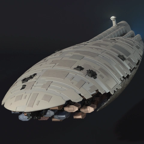
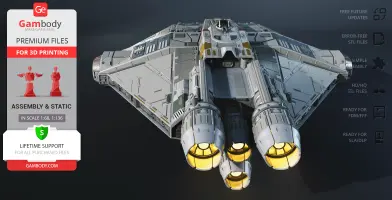
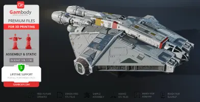
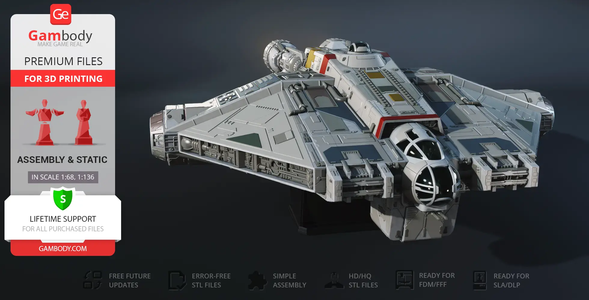
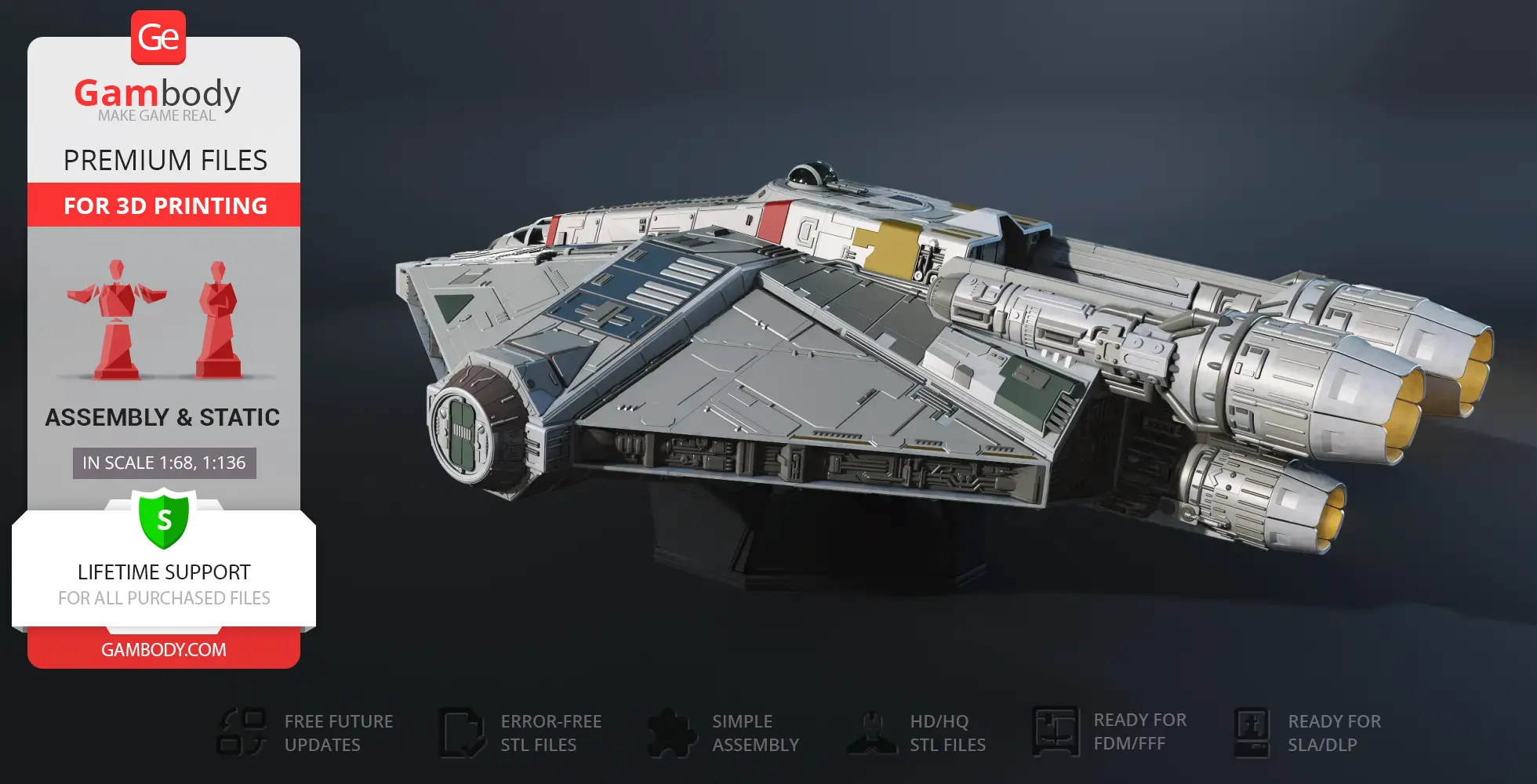
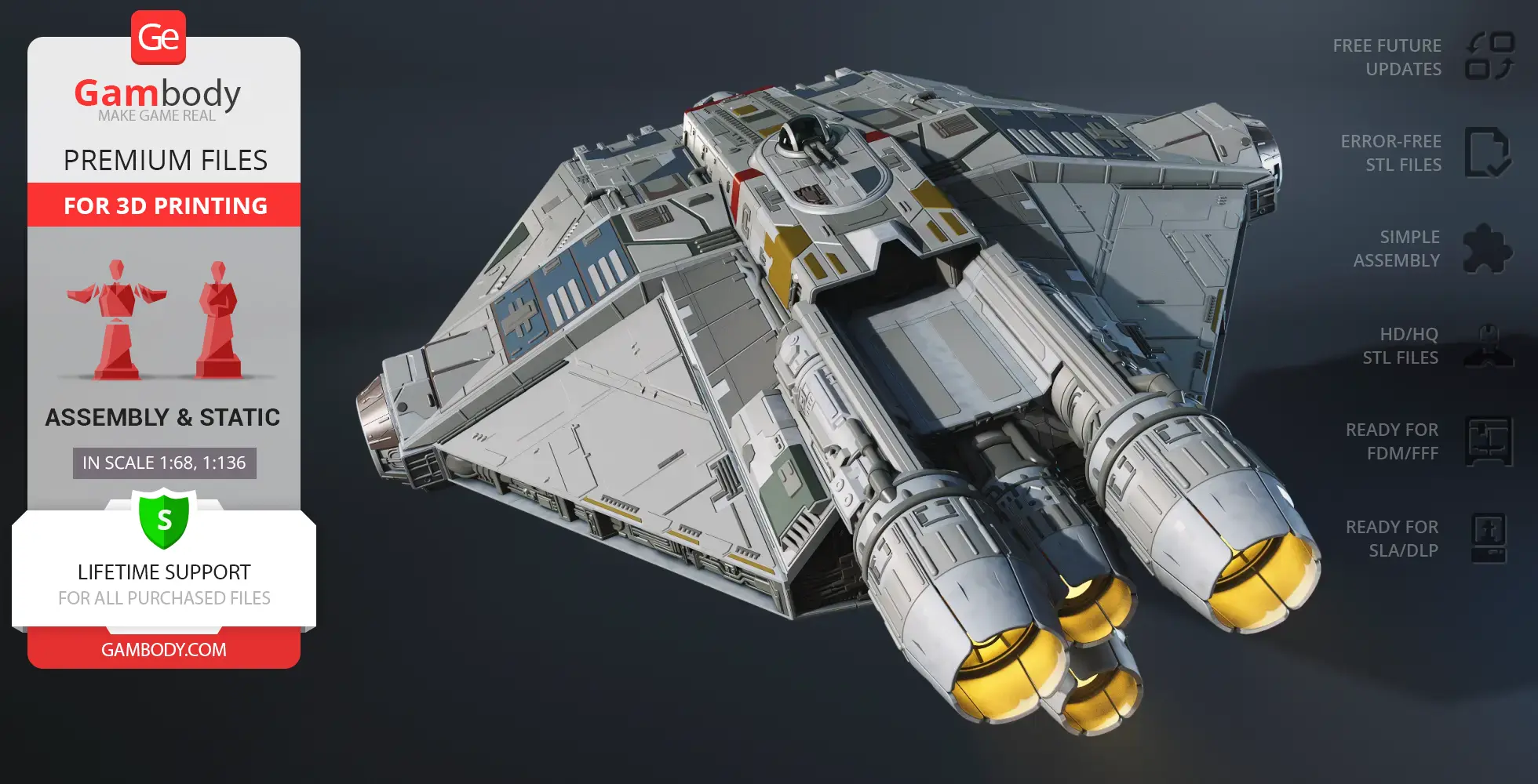
In the Star Wars universe, rebellion didn't start with grand fleets—it began in the cramped, shadowed corridors of a single freighter. The Ghost VCX-100 was never meant to be a symbol, but as it slipped past Imperial scanners like a glitch in the system, it became exactly that. For the people of Lothal and the Spectres crew, this wasn't just a ship; it was a sanctuary. Captained by Hera Syndulla, the Ghost was a tool for survival, designed to move people and supplies quietly while the Empire's eyes were turned elsewhere. Its bulky silhouette and signature forward cockpit have a utilitarian charm, representing a unique side of the Star Wars spaceship design history.

This Ghost VCX-100 3D model brings that defiant legacy to your workbench. Our contributing artist designed it as a premium 3D model of a spaceship, prioritizing interior depth with removable hull sections that expose the ship's secret corridors. You can customize your build with an openable front hangar, a ramp that actually extends, and gear that swaps between landing and flight modes. With articulated turrets and a hollowed-out frame for optional LED lighting, this starship 3D print offers a rewarding project for serious makers. Whether you're adding to a fleet of spacecraft 3D models or looking for a detailed addition to your movie 3D models, this Ghost ship STL honors the idea that even an unassuming freighter can play a part in a much bigger story.

3D printing model features

Model-specific features:

  • This Ghost VCX-100 3D model is a high-detail fan-vision inspired by the specialized rebel freighter from the Star Wars universe.
  • Includes highly detailed corridors and a common room, fully accessible via removable hull covers.
  • Features two types of side docking ports (open and closed) and front hangar doors that can be displayed in an open position.
  • Comes with two types of landing gear, allowing you to display the ship in deployed or retracted modes.
  • The hull is hollowed out to provide ample space for custom LED wiring, with two types of side panels included (with and without pre-drilled holes) to support interior and engine illumination.
  • The model can be placed on its landing gear or mounted on a dedicated display platform.

Printing & assembly details:

  • Provided as error-free STL files compatible with most 3D printers;
  • Optimized part division minimizes support material and ensures smooth surface detail;
  • The assembly parts in the FFF/FDM version come in the recommended print orientations for easy bed placement;
  • Assembly manual in PDF and video formats is included for both FFF/FDM and DLP/SLA versions;
  • The model is available in recommended scales of 1:68 for the FFF/FDM version and 1:136 for the DLP/SLA version.

What will you get after purchase?

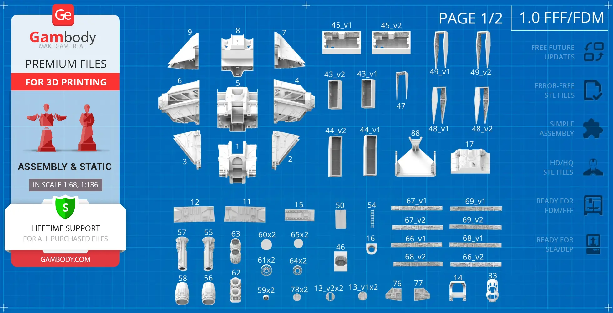
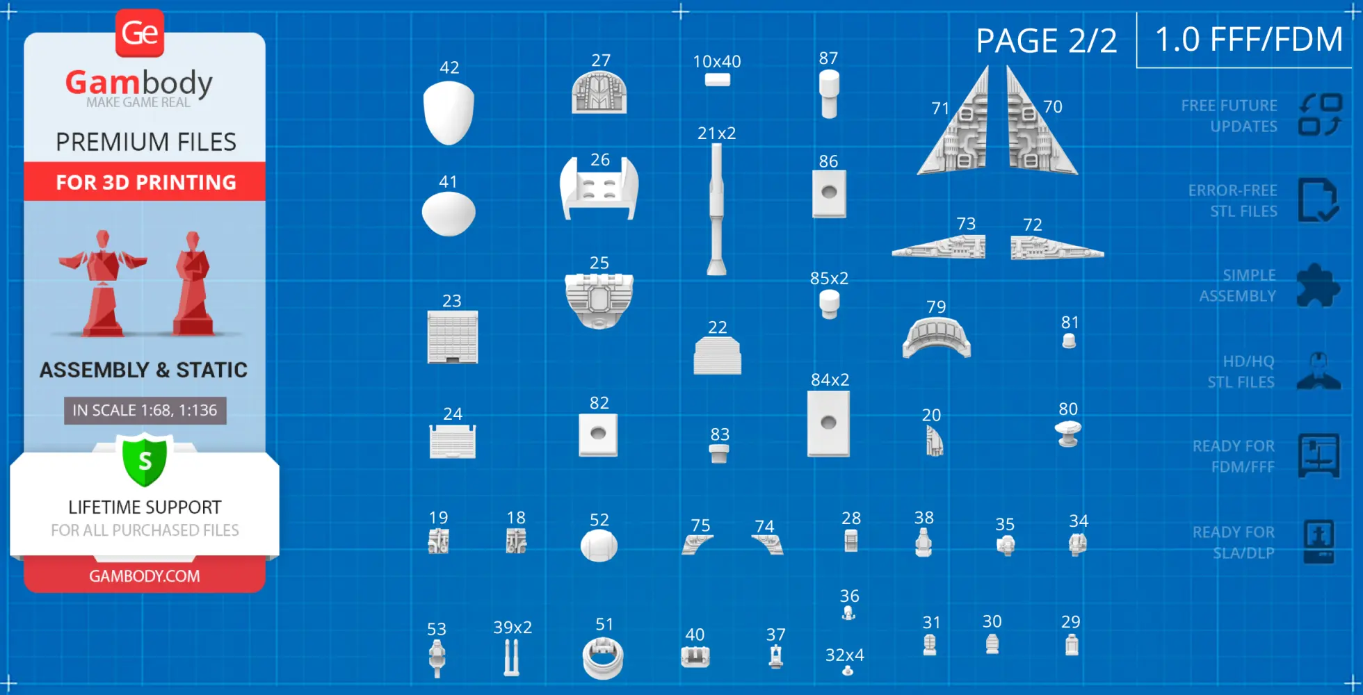
  • 2 versions of Ghost VCX-100STL files for FFF/FDM and DLP/SLA files for all versions are available for download after the purchase;
  • STL files of high-poly Ghost VCX-100 model for 3D printing consist of 170 files;
  • Sizes for:
  • FFF/FDM Model Size: 535 mm wide, 189 mm high, 659 mm deep;
  • FFF/FDM Platform Size: 180 mm wide, 80 mm high, 181 mm deep;
  • DLP/SLA Model Size: 267 mm wide, 95 mm high, 330 mm deep;
  • DLP/SLA Platform Size: 90 mm wide, 40 mm high, 91 mm deep;
  • Assembly Manual for 1.0 FFF/FDM and 1.0 DLP/SLA versions in PDF and video formats;
  • Detailed settings that we provide as a recommendation for Bambu Studio, Cura, Orca Slicer, PrusaSlicer, Simplify3D, and Slic3r for the best print;
  • Full technical support from the Gambody Support Team.
Feedback
Model rating
Overall experience
Level of detail in the model
Model cut quality and assembly guide
Clarity and accuracy of the model page
Enter for new line | Ctrl+Enter to submit text
Printing Details

Below you'll find detailed slicing settings for Bambu Studio 2.0+, Orca Slicer 2.0+, UltiMaker Cura 5.0+, PrusaSlicer 2.0+, Slic3r 1.3+, Simplify3D 5.0+ to help you get the best results when printing this model. These settings are optimized specifically for this 3D model, but please note they may need slight adjustments depending on your printer or filament. When in doubt, refer to your printer's user manual.

Important

To avoid printing issues and achieve the best quality, we highly recommend applying the following settings:

bambu_studio Bambu Studio 2.0+
Settings name
Option
Quality Tab
Layer height
Layer Height
0.12 - 0.20 mm

For better quality use 0.12 mm layer height, for fast printing use 0.2 mm layer height. For pins and the Ge connectors, use 0.2 layer height.

First layer height
0.20 - 0.28 mm

120-150% of your Layer Height

Line width
Default:
0.42 mm
Initial Layer
0.50 - 0.60 mm
Outer wall
0.40 mm
Inner wall
0.45 mm
Top surface
0.45 mm
Sparse infill
0.45 mm
Internal solid infill
0.42 mm
Support
0.42 mm
Seam
Seam position
Aligned

But you can paint the seam if you want.

Smart scarf seam application
Scarf application angle threshold
155.0 °
Scarf steps
10.0
Scarf joint for inner walls
Role-based wipe speed
Precision
Slice gap closing radius
0.0490 mm
Resolution
0.0120 mm
Arc fitting
X-Y hole compensation
0.010 - 0.050 mm

You have to calibrate this parameter

X-Y contour compensation
0.010 - 0.050 mm

You have to calibrate this parameter

Elephant foot compensation
0.10 - 0.20 mm

You have to calibrate this parameter

Wall generator
Wall generator
Classic
Wall transitioning threshold angle
10.0 °
Wall transitioning filter margin
25.0 %
Wall transition length
100.0 %
Minimum wall width
85.0 %
Minimum feature size
25.0 %
Advanced
Order of walls
inner/outer
Bridge flow
0.85
Only one wall on top surfaces
Top surfaces
Smooth speed discontinuity area
Smooth coefficient
80.0
Strength
Walls
Wall loops
2 - 3

For pins and power elements of the structure, such as the vehicle frame, use 3 loop

Detect thin wall

Disabled for vehicles and enabled for characters

Top/bottom shells
Top surface pattern
Monotonic
Top shell layers
5

For 0,2 Layer Height

Top shell thickness
1.00 mm
Top paint penetration layers
5
Bottom surface pattern
Monotonic
Bottom shell layers
5
Bottom shell thickness
1.00 mm
Bottom paint penetration layers
5
Internal solid infill pattern
Rectilinear
Sparse infill
Sparse infill density
6.0 %
Sparse infill pattern
Triangles
Length of sparse infill anchor
400.0 %
Maximum length of sparse infill anchor
20.0 mm
Advanced
Infill/Wall overlap
15.0 - 25.0 %
Infill direction
45.0 °
Bridge direction
0.0 °
Minimum sparse infill threshold
10.0 mm²
Detect narrow internal solid infill
Ensure vertical shell thickness
Enabled
Detect floating vertical shells
Speed

The parameters in this tab vary greatly, it all depends on the quality of your printer. For example, if you have a classic Ender3, stick to the minimum parameters, but if you have a newer printer, for example Anycubic cobra 3 v2, you can select the maximum recommended values

Initial layer speed
Initial layer
15.0 - 45.0 mm/sec
Initial layer infill
35.0 - 75.0 mm/sec
Other layers speed
Outer wall
30.0 - 150.0 mm/sec
Inner wall
30.0 - 250.0 mm/sec
Small perimeters
50.0 %
Small perimeter threshold
0.1 mm
Sparse infill
50.0 - 250.0 mm/sec
Internal solid infill
50.0 - 200.0 mm/sec
Vertical shell speed
80.0 %
Top surface
25.0 - 150.0 mm/sec
Slow down for overhangs
Overhang speed
Overhang speed 10%
0.0 mm/sec
Overhang speed 25%
40.0 mm/sec
Overhang speed 50%
20.0 mm/sec
Overhang speed 75%
10.0 mm/sec
Overhang speed 100%
10.0 mm/sec
Bridge
20.0 - 40.0 mm/sec
Gap infill
30.0 - 150.0 mm/sec
Support
30.0 - 100.0 mm/sec
Support interface
30.0 - 60.0 mm/sec
Travel speed
Travel
80.0 - 350.0 mm/sec
Acceleration

Settings for advanced users, change these parameters only if you have sufficient 3D printing expertise

Normal printing
2,500.0 - 4,000.0 mm/sec²
Travel
2,000.0 - 7,000.0 mm/sec²
Initial layer travel
700.0 - 5,000.0 mm/sec²
Initial layer
500.0 - 3,000.0 mm/sec²
Outer wall
500.0 - 3,000.0 mm/sec²
Inner wall
500.0 - 4,000.0 mm/sec²
Top surface
500.0 - 2,500.0 mm/sec²
Sparse infill
100.0 - 100.0 %
Support
Support
Enable support

Enable this parameter if your model requires supports

Type
Tree (auto)
Style
Default
Threshold angle
10.0 - 60.0 °

We also recommend placing and removing supports manually in some places using special button

Remove small overhangs
Raft
Raft layers
0 layers
Advanced
Initial layer density
90.0 %
Initial layer expansion
-1.0 mm
Support wall loops
-1 - 2

1-2 loops for more thick support

Top Z distance
0.20 - 0.25 mm

Top Z distance = 1-1.3 layer Height. If the supports are hard to remove, try increasing this setting by 0.1-0,4 mm

Bottom Z distance

Bottom Z distance = 1-1.3 layer Height. If the supports are hard to remove, try increasing this setting by 0.1-0,4 mm

Base pattern
Rectilinear
Base pattern spacing
2.50 mm
Pattern angle
0.0 °
Top interface layers
2 - 3 layers
Interface pattern
Concentric
Top interface spacing
0.00 - 0.50 mm

You have to calibrate this parameter which one is better for your filament

Normal Support expansion
0.00 mm
Support/object xy distance
0.35 - 0.80 mm

Increase this parameter if the supports are hard to remove from walls

Support/object first layer gap
0.35 mm
Max bridge length (only for tree supports)
1.0 mm
Independent support layer height
Tree Support (only for tree supports)
Branch distance
5.0 mm
Branch diameter
2.0 mm
Branch angle
45.0 °
Branch diameter angle
5.0 °
Others
Bed adhesion
Skirt loops
0
Skirt height
1 layers

For PLA and PETG filament types

Brim type
Outer and inner brim
Brim width
5.00 mm

5-8 mm is optional for small prints that have bad adhesion to the build plate


Brim-object gap
0.01 - 0.12 mm
Prime tower
Enable
Skip points
Width
35.0 mm
Max speed
90.0 mm/sec
Brim width
3.0 mm
Infill gap
150.0 %
Rib wall
Rib width
8.0 mm
Fillet wall
Flush options
Flush into objects support
Special mode
Slicing Mode
Regular
Print sequence
By layer
Timelapse
Traditional
G-code output
Reduce infill retraction
Filament settings
Filament
Type
PLA
Filament ramming length
10.0 mm
Filament prime volume
45.0 mm³
Diameter
1.75 mm
Flow ratio
0.90 - 1.10

You have to calibrate this parameter

Shrinkage
100.0 %
Velocity Adaptation Factor
1.0
Softening temperature
45.0 - 80.0 ⁰C

Read the description on your filament roll

Travel time after ramming
0.0 sec
Precooling target temperature
0.0 ⁰C
Recommended nozzle temperature
190.0 - 270.0 ⁰C

Read the description on your filament roll and increase this parameter for fast printers

Print temperature
Cool Plate SuperTack
45.0 - 45.0 ⁰C
Cool Plate
35.0 - 35.0 ⁰C
Engineering Plate
0.0 - 0.0 ⁰C
Smooth PEI Plate / High
65.0 - 65.0 ⁰C
Temp Plate
65.0 - 65.0 ⁰C
Textured PEl Plate
65.0 - 65.0 ⁰C
Nozzle
220.0 - 270,200.0 ⁰C

Read the description on your filament roll and increase this parameter for fast printers

Volumetric speed limitation
Max volumetric speed
12.0 mm/sec
Ramming volumetric speed
-1.0 mm/sec
Filament scarf seam settings
Scarf start height
10.0 %
Scarf length
10.0 mm
Cooling
Cooling for specific layer
1 layers
No cooling for the first
1 layers
Part cooling fan
Min fan speed threshold
Fan speed
60.0 %
Layer time
90.0 sec
Max fan speed threshold
Fan speed
80.0 %
Layer time
8.0 sec
Keep fan always on
Slow printing down for better layer cooling
Min print speed
10.0 mm/sec
Force cooling for overhangs and bridges
Cooling overhang threshold
50.0 %
Overhang threshold for participating cooling
100.0 %
Fan speed for overhangs
100.0 %
Pre start fan time
0.0 sec
Auxiliary part cooling fan
Fan speed
70.0 %
Printer Settings Tab
Motion ability
Jerk limitation
Maximum jerk X
7.0 mm/sec
Maximum jerk Y
7.0 mm/sec
Maximum jerk Z
0.4 mm/sec
Maximum jerk E
5.0 mm/sec
Extruder
Basic information
Type
Direct drive extruder
Nozzle diameter
0.40 mm
Nozzle volume
0.0 mm³
Layer height limits
Min
0.08 mm
Max
0.35 mm
Retraction
Length
0.70 mm
Z hop when retract
0.3 mm
Z hop lower boundary
0.0 mm
Z Hop Type
Normal
Retraction Speed
30.0 mm/sec
Deretraction Speed
30.0 mm/sec
Travel distance threshold
1.0 mm
Retract when change layer
Wipe while retracting
Wipe Distance
2.0 mm
Retract amount before wipe
70.0 %
orca_slicer Orca Slicer 2.0+
Settings name
Option
Quality Tab
Layer height
Layer Height
0.12 - 0.20 mm

For better quality use 0.12 mm layer height, for fast printing use 0.2 mm layer height. For pins and the Ge connectors, use 0.2 layer height.

First layer height
0.20 - 0.28 mm

120-150% of your Layer Height

Line width
Default:
0.42 mm
Initial Layer
0.45 - 0.50 mm
Outer wall
0.42 mm
Inner wall
0.45 mm
Top surface
0.45 mm
Sparse infill
0.45 mm
Internal solid infill
0.45 mm
Support
0.42 mm
Seam
Seam position
Aligned

But you can paint the seam if you want.

Seam gap
10.0 %
Role base wipe speed
Wipe speed
80.0 %
Precision
Slice gap closing radius
0.049 mm
Resolution
0.012 mm
X-Y hole compensation
0.01 mm

0.01-0.05 You have to calibrate this parameter

X-Y contour compensation
0.01 mm

0.01-0.05 You have to calibrate this parameter

Elephant foot compensation
0.10 mm

0.1-0.2 You have to calibrate this parameter

Elephant foot compensation layers
1 layers
Ironing
Ironing Type
No ironing
Wall generator
Wall generator
Arachne
Wall transitioning threshold angle (Arachne setting)
10.0 °
Wall transitioning filter margin (Arachne setting)
25.0 %
Wall transition length (Arachne setting)
100.0 %
Wall distribution count (Arachne setting)
1
First layer minimum wall width (Arachne setting)
85.0 %
Minimum wall width (Arachne setting)
85.0 %
Minimum feature size (Arachne setting)
25.0 %
Minimum wall length (Arachne setting)
0.50 mm
Walls and surfaces
Walls printing order
inner/outer
Wall loop direction
Auto
Top surface flow ratio
1.00
Bottom surface flow ratio
1.00
Only one wall on top surfaces
One wall threshold
300.0 %
Bridging
Bridge flow ratio
0.95 - 1.05
Internal bridge flow ratio
0.95 - 1.05
External bridge density
100.0 %
Internal bridge density
100.0 %
Thick internal bridges
Extra bridge layers (beta)
Disabled
Filter out small internal bridges
Filter
Bridge counterbore holes
None
Overhangs
Detect overhang walls
Strength
Walls
Wall loops

For pins and power elements of the structure, such as the vehicle frame, use 3 loop

Detect thin walls

Disabled for vehicles and ships, enabled for characters

Top/bottom shells
Top shell layers
5 layers

For 0,2 Layer Height

Top shell thickness
1.00 mm
Top surface density
100 %
Top surface pattern
Monotonic line
Bottom shell layers
5 layers

For 0,2 Layer Height

Bottom shell thickness
1.00 mm
Bottom surface density
100.0 %
Bottom surface pattern
Monotonic
Top/Bottom solid infill/wall overlap
25.0 %
Infill
Sparse infill density
5.0 %
Fill Multiline
1.00
Sparse infill pattern
Triangles
Sparse infill direction
45.0 °
Maximum length of the infill anchor
20.0 mm
Sparse infill anchor length
400.0 %
Internal solid infill pattern
Monotonic
Solid infill direction
45.0 °
Apply gap fill
Nowhere
Filter out tiny gaps
0.00 mm
Infill/wall overlap
10.0 - 25.0 %
Advanced
Insert solid layers
-1
External bridge infill direction
0.0 °
Internal bridge infill direction
0.0 °
Minimum sparse infill threshold
15.0 mm²
Detect narrow internal solid infill
Ensure vertical shell thickness
All
Speed

The parameters in this tab vary greatly, it all depends on the quality of your printer. For example, if you have a classic Ender3, stick to the minimum parameters, but if you have a newer printer, for example, Anycubic Kobra 3 Or Bambulab A1, you can select the maximum recommended values.


First layer speed
First layer
15.0 - 45.0 mm/sec
First layer infill
35.0 - 75.0 mm/sec
Initial layer travel speed
50.0 %
Number of slow layers
2 layers
Other layers speed
Outer wall
30.0 - 150.0 mm/sec
Inner wall
30.0 - 250.0 mm/sec
Small perimeters
50.0 %
Small perimeter threshold
0.1 mm
Sparse infill
50.0 - 250.0 mm/sec
Internal solid infill
50.0 - 250.0 mm/sec
Top surface
30.0 - 150.0 mm/sec
Gap infill
30.0 - 200.0 mm/sec
Slow down by height
Overhang speed
Slow down for overhangs
Slow down for curled perimeters
Overhang speed 10%, 25%
0.0 mm/sec
Overhang speed 25%, 50%
50.0 mm/sec
Overhang speed 50%, 75%
30.0 mm/sec
Overhang speed 75%, 100%
10.0 mm/sec
Bridge external
20.0 - 40.0 mm/sec
Bridge internal
30.0 mm/sec
Travel speed
Travel
100.0 - 300.0 mm/sec
Acceleration

Settings for advanced users, change these parameters only if you have sufficient 3D printing expertise

Normal printing
5,000.0 mm/sec²
Outer wall
3,000.0 mm/sec²
Inner wall
3,000.0 mm/sec²
Bridge
50.0 %
Sparse infill
100.0 %
Internal solid infill
100.0 %
First layer
300.0 mm/sec²
Top surface
3,000.0 mm/sec²
Travel
5,000.0 mm/sec²
accel to decel
50.0 %
Jerk(XY)
Default
9.0 mm/sec
Outer wall
7.0 mm/sec
Inner wall
7.0 mm/sec
Infill
10.0 mm/sec
Top surface
7.0 mm/sec
First layer
9.0 mm/sec
Travel
12.0 mm/sec
Support
Support
Enable support

Enable this parameter if your model requires supports

Type
Tree (auto)
Style
Default
Threshold angle
60.0 °

We also recommend placing and removing supports manually in some places using special button

Threshold overlap
50.0 %
First layer density
90.0 %
First layer expansion
2.0 mm
Remove small overhangs
Raft
Raft layers
0 layers
Advanced
Top Z distance
0.20 - 0.25 mm

Top Z distance = 1-1.3 layer Height. If the supports are hard to remove, try increasing this setting by 0.1-0,4 mm

Bottom Z distance
0.20 - 0.25 mm

Bottom Z distance = 1-1.3 layer Height. If the supports are hard to remove, try increasing this setting by 0.1-0,4 mm

Support wall loops
0
Base pattern
Rectilinear
Base pattern spacing
2.50 mm
Pattern angle
0.0 °
Top interface layers
2 layers
Bottom interface layers
2 layers
Interface pattern
Rectilinear
Top interface spacing
0.00 mm
Bottom interface spacing
0.00 mm
Normal Support expansion
0.00 mm
Support/object xy distance
0.40 mm

Increase this parameter if the supports are hard to remove from walls

Support/object first layer gap
0.35 mm
Independent support layer height
Tree Support (only for tree supports)
Tip Diameter
0.80 mm
Tree support branch distance
1.00 mm
Branch Density
30.0 %
Tree support branch diameter
2.0 mm
Branch Diameter Angle
5.0 °
Tree support branch angle
40.0 °
Preferred Branch
25.0 °
Others
Skirt
Skirt loops
0
Skirt type
Combined
Skirt minimum extrusion length
0.00 mm
Skirt distance
2.00 mm
Skirt start point
-135.0 °
Skirt speed
50.0 mm/sec
Skirt height
1.0 layers

For PLA and PETG filament types

Draft shield
Disabled
Brim
Brim type
Outer and inner brim
Brim width
5.0 mm

5-8 mm is optional for small prints that have bad adhesion to the build plate

Brim-object gap
0.01 - 0.12 mm
Special mode
Slicing Mode
Regular
Print sequence
By layer
Intra-layer order
Default
G-code output
Label objects
Filename format
{input _filename_ base}_{print_time}.gcode
Filament Tab
Filament
Basic information
Type
PLA
Shrinkage (XY)
100.0 %
Shrinkage (Z)
100.0 %
Softening temperature
60.0 ⁰C

Read the description on your filament roll

Idle temperature
0.0 ⁰C
Recommended nozzle temperature
190.0 - 270.0 ⁰C

Read the description on your filament roll and increase this parameter for fast printers

Flow ratio and Pressure Advance
Flow ratio
0.90 - 1.10

You have to calibrate this parameter

Print chamber temperature
Chamber temperature
0.0 ⁰C
Print temperature
Nozzle

Read the description on your filament roll and increase this parameter for fast printers

First layer
190.0 - 270.0 ⁰C
Other layers
190.0 - 270.0 ⁰C
Bed temperature

Read the description on your filament roll

Cool Plate (SuperTack)
First layer
45.0 ⁰C
Other layers
45.0 ⁰C
Cool Plate
First layer
35.0 ⁰C
Other layers
35.0 ⁰C
Textured Cool Plate
First layer
40.0 ⁰C
Other layers
40.0 ⁰C
Engineering Plate
First layer
0.0 ⁰C
Other layers
0.0 ⁰C
Smooth PEI Plate / High Temp Plate
First layer
55.0 ⁰C
Other layers
55.0 ⁰C
Textured PEI Plate
First layer
55.0 ⁰C
Other layers
55.0 ⁰C
Volumetric speed limitation
Max volumetric speed
21.0 mm/sec
Cooling
Cooling for specific layer
No cooling for the first
1.0 layers
Full fan speed at layer
3.0 layers
Part cooling fan
Min fan speed threshold
Fan speed
70.0 %
Layer time
80.0 sec
Max fan speed threshold
Fan speed
80.0 %
Layer time
6.0 sec
Keep fan always on
Slow printing down for better layer cooling
Min print speed
9 mm/sec
Force cooling for overhangs and bridges
Overhang cooling activation threshold
50.0 %
Overhangs and external bridges fan speed
100.0 %
Internal bridges fan speed
-1.0 %
Support interface fan speed
-1.0 %
Ironing fan speed
-1.0 %
Auxiliary part cooling fan
Fan speed
70.0 %
Exhaust fan
During print
69.9 %
Complete print
70.0 %
Printer Settings Tab
Basic information

This field is filled in according to your printer specifications when you add it to the slicer.

Machine G-code

You can add custom G-code here for the start and end of the print. However, be careful - this is for advanced users only!

Extruder 1
Size
Nozzle diameter
0.4 mm
Layer height limits
Min
0.1 mm
Max
0.3 mm
Retraction

You have to calibrate your printer using Ge retraction test models

Length
0.6 mm

Retraction Length: For direct-drive setups use 0.5 mm to 2.5 mm; for Bowden extruders use 5 to 7 mm

Extra length on restart
0.00 mm
Retraction speed
40 mm/sec
Deretraction speed
40.0 mm/sec

This is how fast the filament is pulled back—40-60 mm/s for direct drive and 30-50 mm/s for Bowden setups.

Travel distance threshold
1.00 mm
Retract on layer change
Wipe while retracting
Wipe distance
2.00 mm
Retract amount before wipe
70.0 %
Z-Hop
On surfaces
All surfaces
Z-hop type
Auto
Z-hop height
0.30 mm

You have to calibrate this parameter: Reduce it until the printer starts to hit the parts with the nozzle during printing, then increase it by 0.2.

Traveling angle
3.0 °
Only lift Z above
0.00 mm
Only lift Z below
0.00 mm
Retraction when switching material
Length
1.00 mm
Extra length on restart
0.00 mm
cura UltiMaker Cura 5.0+
Settings name
Option
Quality
Layer Height
0.12 - 0.20 mm

For better quality use 0.12 mm layer height, for fast printing use 0.2 mm layer height. For pins and the Ge connectors, use 0.2 layer height.

Initial Layer Height
0.20 mm

120-150% of your Layer Height

Line Width
0.42 mm
Wall Line Width
0.40 mm
Outer Wall Line Width
0.40 mm
Inner Wall(s) Line Width
0.42 mm
Top/Bottom Line Width
0.44 mm
Infill Line Width
0.40 mm
Skirt/Brim Line Width
0.42 mm
Initial Layer Line Width
0.5 %
Walls
Wall Thickness
0.80 mm
Wall Line Count
2

To increase the strength of the print parts, use wall line count: 3

Wall Transition Length
0.20 mm
Wall Distribution Count
1
Wall Transitioning Threshold Angle
10.0 °
Wall Transitioning Filter Margin
0.10 mm
Outer Wall Wipe Distance
0.00 mm
Optimize Wall Printing Order
Wall Ordering
Inside to Outsize
Minimum Wall Line Width
0.34 mm
Minimum Even Wall Line Width
0.34 mm
Minimum Odd Wall Line Width
0.34 mm
Print Thin Walls
Minimum Feature Size
0.10 mm
Minimum Thin Wall Line Width
0.34 mm
Horizontal Expansion
0.00 mm
Initial Layer Horizontal Expansion
0.00 mm
Hole horizontal expansion
0.00 mm
Z Seam Alignment
User Specified
Z Seam Position
Back
Z Seam X
0.0 mm
Z Seam Y
200.0 mm
Top/Bottom
Top Surface Skin Layers
0 layers
Bottom Surface Skin Layers
0 layers
Top/Bottom Thickness
1.00 mm
Top Thickness
1.00 mm
Bottom Thickness
1.00 mm
Initial Bottom Layers
4 - 5 layers
Top/Bottom Pattern
Lines
Bottom Pattern Initial Layer
Lines
Extra Skin Wall Count
1
Enable Ironing
Infill

For pins and connectors use 50% Infill

Infill Density
5.0 - 30.0 %
Infill Line Distance
6.00 mm
Infill Pattern
Triangles
Infill X Offset
0.00 mm
Infill Y Offset
0.00 mm
Infill Line Multiplier
1
Infill Overlap Percentage
30.0 %
Infill Overlap
0.12 mm
Infill Wipe Distance
0.00 mm
Infill Layer Thickness
0.20 mm
Gradual Infill Steps
0
Minimum Infill Area
0.00 mm²
Skin Edge Support Thickness
0.00 mm
Skin Edge Support Layers
0
Extra Infill Lines To Support Skins
Walls and Lines
Material

These parameters are for standard PLA plastic. If you are using a different type of plastic, check the printing temperature recommended by the manufacturer. Also, read the description on your filament spool. For fast printers, add +30 °C to the current parameters.


Printing Temperature
210.0 ⁰C
Printing Temperature Initial Layer
210.0 ⁰C
Initial Printing Temperature
210.0 ⁰C
Final Printing Temperature
210.0 ⁰C
Build Plate Temperature
60.0 ⁰C
Build Plate Temperature Initial Layer
60.0 ⁰C
Scaling Factor Shrinkage Compensation
100.0 %
Horizontal Scaling Factor Shrinkage Compensation
100.0 %
Vertical Scaling Factor Shrinkage Compensation
100.0 %
Flow
98.0 - 102.0 %
Wall Flow
-0.1 %
Speed

The parameters in this tab vary greatly, it all depends on the quality of your printer. For example, if you have a classic Ender3, stick to the minimum parameters, but if you have a newer printer, for example Anycubic cobra 3 v3, you can select the maximum recommended values

Print Speed
60.0 - 160.0 mm/sec
Infill Speed
60.0 - 160.0 mm/sec
Wall Speed
30.0 - 90.0 mm/sec
Outer Wall Speed
30.0 - 90.0 mm/sec
Inner Wall Speed
40.0 - 80.0 mm/sec
Top/Bottom Speed
40.0 - 100.0 mm/sec
Travel Speed
100.0 - 250.0 mm/sec
Initial Layer Speed
15.0 - 30.0 mm/sec
Initial Layer Print Speed
15.0 - 30.0 mm/sec
Initial Layer Travel Speed
100.0 - 150.0 mm/sec
Skirt/Brim Speed
20.0 - 30.0 mm/sec
Number of Slower Layers
2.0 layers
Flow Equalization Ratio
100.0 %
Enable Acceleration Control

Settings for advanced users, change these parameters only if you have sufficient 3D printing expertise.

Print Acceleration
500.00 - 3,000.00 mm/sec²
Infill Acceleration
500.0 - 3,000.0 mm/sec²
Wall Acceleration
500.0 - 2,000.0 mm/sec²
Outer Wall Acceleration
500.0 - 2,000.0 mm/sec²
Inner Wall Acceleration
500.0 - 3,000.0 mm/sec²
Top/Bottom Acceleration
500.0 - 2,000.0 mm/sec²
Travel Acceleration
500.0 - 4,000.0 mm/sec²
Initial Layer Acceleration
500.0 - 1,000.0 mm/sec²
Initial Layer Print Acceleration
500.0 - 1,000.0 mm/sec²
Initial Layer Travel Acceleration
500.0 - 3,000.0 mm/sec²
Skirt/Brim Acceleration
500.0 - 2,500.0 mm/sec²
Travel
Enable Retraction
Retraction Distance
0.8 mm

You need to calibrate this parameter using Gambody test models. These values are average values for a Direct Drive extruder; for a Bowden extruder, the values should be increased.

Retraction Speed
35.0 - 50.0 mm/sec

You need to calibrate this parameter using Gambody test models. These values are average values for a Direct Drive extruder; for a Bowden extruder, the values should be increased.

Retraction Retract Speed
40.0 mm/sec
Retraction Prime Speed
40.0 mm/sec
Retraction Extra Prime Amount
0.00 mm³
Retraction Minimum Travel
1.49 mm
Maximum Retraction Count
100
Minimum Extrusion Distance Window
2.00 - 3.00 mm
Combing Mode
All
Retract Before Outer Wall
Layer Start X
0.00 mm
Layer Start Y
0.00 mm
Z Hop When Retracted

Use this value other than 0 if your nozzle catches on the internal infill during travel moves. Try to keep this value as low as possible in height.

Cooling
Enable Print Cooling
Fan Speed
100.0 %
Regular Fan Speed
100.0 %
Maximum Fan Speed
100.0 %
Regular/Maximum Fan Speed Threshold
10.0 sec
Initial Fan Speed
0.0 %
Regular Fan Speed at Height
0.5 mm
Regular Fan Speed at Layer
3 layers
Minimum Layer Time
5.0 sec
Minimum Speed
10.0 mm/sec
Cooling during extruder switch
Unchanged
Support
Generate Support
Support Structure Normal

Use normal supports to support large, straight surfaces (most mechanical or technical parts).

Support Z Seam Away from Model
Min Z Seam Distance from Model
0.80 mm
Support Placement
Everywhere
Support Overhang Angle
45.0 - 65.0 °

You have to calibrate this parameter according to the capabilities of your printer and your filament, using a Gambody test models.

Support Pattern
Zig Zag
Support Wall Line Count
0

Use 1 instead of 0 if your supports are thin and tall. They will be harder to remove, but much stronger.

Support Interface Wall Line Count
0
Support Roof Wall Line Count
0
Support Bottom Wall Line Count
0
Connect Support ZigZags
Support Density
5.0 - 20.0 %
Support Line Distance
2.0 - 8.0 mm
Enable Support Brim
Support Brim Width
4.0 mm
Support Brim Line Count
10
Support Z Distance
0.24 mm

Top Z distance = 1-1.3 layer Height. If the supports are hard to remove, try increasing this setting by 0.1-0,4 mm

Support Top Distance
0.24 mm
Support Bottom Distance
0.24 mm
Support X/Y Distance
0.80 mm

Increase this parameter if the supports are hard to remove from walls

Support Distance Priority
X/Y overrides Z
Support Stair Step Height
0.00 mm
Support Join Distance
2.00 mm
Support Horizontal Expansion
0.80 mm
Support Infill Layer Thickness
0.20 mm
Gradual Support Infill Steps
0
Minimum Support Area
2.0 mm²
Enable Support Interface
Enable Support Roof
Enable Support Floor
Support Interface Thickness
0.40 mm
Support Roof Thickness
0.40 mm
Support Floor Thickness
0.40 mm
Support Interface Density
33.33 - 33.33 %
Support Roof Density
33.33 - 33.33 %
Support Roof Line Distance
2.40 mm
Support Floor Density
33.3 - 33.3 %
Support Floor Line Distance
2.40 mm
Support Interface Pattern
Concentric
Support Roof Pattern
Concentric
Support Floor Pattern
Concentric
Minimum Support Interface Area
10.0 mm²
Minimum Support Roof Area
10.0 mm²
Minimum Support Floor Area
10.0 mm²
Support Interface Horizontal Expansion
0.0 mm
Support Roof Horizontal Expansion
0.0 mm
Support Floor Horizontal Expansion
0.0 mm
Use Towers
Tower Diameter
3.0 mm
Maximum Tower-Supported Diameter
3.0 mm
Tower Roof Angle
65.0 °
Support Structure Tree

Use tree supports to support complex objects, such as characters.

Maximum Branch Angle
45.0 °

You have to calibrate this parameter according to the capabilities of your printer and your filament, using a Gambody test models.

Branch Diameter
5.0 mm
Trunk Diameter
25.0 mm
Branch Diameter Angle
7.0 °
Support Z Seam Away from Model
Min Z Seam Distance from Model
0.80 mm
Support Placement
Everywhere
Preferred Branch Angle
30.0 °
Diameter Increase To Model
1.0 mm
Minimum Height To Model
3.0 mm
Initial Layer Diameter
7.5 mm
Branch Density
30.0 %
Tip Diameter
0.8 mm
Limit Branch Reach
Optimal Branch Range
30.0 mm
Rest Preference
On model if required
Support Overhang Angle
45.0 °
Support Pattern
Zig Zag
Support Wall Line Count
1
Support Interface Wall Line Count
0
Support Roof Wall Line Count
0
Support Bottom Wall Line Count
0
Connect Support ZigZags
Support Density
0.0 %
Support Line Distance
0.0 %
Initial Layer Support Line Distance
0.0 %
Support Infill Density Multiplier Initial Layer
1
Enable Support Brim
Support Brim Width
4.0 mm
Support Brim Line Count
10
Support Z Distance
0.24 mm

Top Z distance = 1-1.3 layer Height. If the supports are hard to remove, try increasing this setting by 0.1-0,4 mm

Support Top Distance
0.22 mm
Support Bottom Distance
0.22 mm
Support X/Y Distance
0.22 mm

Increase this parameter if the supports are hard to remove from walls

Support Distance Priority
X/Y overrides Z
Minimum Support Area
0.00 mm²
Enable Support Interface
Enable Support Roof
Enable Support Floor
Support Interface Thickness
0.80 mm
Support Roof Thickness
0.80 mm
Support Floor Thickness
0.80 mm
Support Interface Density
33.33 mm
Support Roof Density
33.33 %
Support Floor Density
2.39 %
Support Interface Pattern
Grid
Support Roof Pattern
Grid
Support Floor Pattern
Grid
Minimum Support Interface Area
10.00 mm²
Minimum Support Roof Area
10.00 mm²
Support Interface Horizontal Expansion
0.00 mm
Support Roof Horizontal Expansion
0.00 mm
Support Floor Horizontal Expansion
0.00 mm
Support Interface Priority
Interface preferred
Build Plate Adhesion
Build plate type: Skirt

Use a skirt for all parts when printing on outdated printers.

Skirt Line Count
3.00
Skirt Height
3.00
Skirt Distance
10.00 mm
Skirt/Brim Minimum Length
250 mm
Build plate type: Brim

Use a brim when printing thin but tall parts, as well as parts with a small bed adhesion area.

Skirt/Brim Minimum Length
250.0 mm
Brim Width
10.0 mm
Brim Line Count
25
Brim Distance
0.0 mm
Brim Location
Outside Only
Brim Avoid Margin
1.6 mm
Smart Brim
Z Offset
0.0 mm
prusa_slicer PrusaSlicer 2.0+
Settings name
Option
Print Settings Tab
Layers and perimeters
Layer height
Layer Height
0.12 - 0.20 mm

For better quality use 0.12 mm layer height, for fast printing use 0.2 mm layer height. For pins and the Ge connectors, use 0.2 layer height.

First layer height
0.18 - 0.28 mm

120-150% of your Layer Height

Vertical shells
Perimeters
2 - 3
Horizontal shells
Solid layers top
4

for 0.2 Layer Height

Solid layers bottom
4
Minimum shell thickness top
0.80 mm
Minimum shell thickness bottom
0.80 mm
Quality (slower slicing)
Extra perimeters if needed
Ensure vertical shell thickness
Enabled
Advanced
Seam position
Aligned

But you can paint the seam if you want.

Seam gap distance
15.0 %
Scarf joint placement
Nowhere
External perimeters first
Fill gaps
Perimeter generator
Arachne
Fuzzy skin (experimental)
Fuzzy Skin
None
Fuzzy skin thickness
0.30 mm
Fuzzy skin point distance
0.80 mm
Only one perimeter
Single perimeter on top surfaces
Disabled
Infill
Infill
Fill Density
6.0 %
Fill Pattern
Triangles
Length of the infill anchor
10.00 mm
Maximum length of the infill anchor
10.00 mm
Top Fill Pattern
Monotonic Lines
Bottom fill pattern
Monotonic Lines
Ironing
Enable ironing
Skirt and brim
Skirt
Loops (minimum)
0
Distance from brim/object
6.00 mm
Skirt height
1 layers

(for PLA and PETG)

Minimal filament extrusion length
50.00 mm
Brim
Brim type
Outer brim only
Brim width
5.00 - 8.00 mm

(5-8 mm is optional for small prints that have bad adhesion to the build plate)


Brim separation gap
0.12 mm
Support material
Support material
Generate support material

Enable this parameter if your model requires supports

Auto generated supports
Overhang threshold
60.0 °

(45-50 degree)You have to calibrate this parameter according to the capabilities of your printer

and your filament, using a Gambody test models.

Enforce support for the first
2 layers
First layer density
90.0 %
First layer expansion
3.0 mm
Raft
Raft layers
0 layers
Options for support material and raft
Style
Grid
Top contact Z distance
0.24 mm

Top contact Z distance = 1-1.3 layer Height. If the supports are hard to remove, try

increasing this setting by 0.1-0,4 mm

Bottom contact Z distance
0.24 mm

Top contact Z distance = 1-1.3 layer Height. If the supports are hard to remove, try

increasing this setting by 0.1-0,4 mm

Pattern
Rectilinear
Pattern spacing
2.5 mm
Pattern angle
0.0 °
Top interface layers
2 layers
Bottom interface layers
2 layers
Interface pattern
Concentric
Intertace pattern spacing
0.00 mm
XY separation between an object and its support
1.00 mm

Increase this parameter if the supports are hard to remove from walls

Don't support bridges
Organic supports
Maximum Branch Angle
45.0 °
Preferred Branch Angle
30.00 °
Branch Diameter
2.00 mm
Branch Diameter Angle
5.00 °
Branch Diameter with double walls
3.00 mm
Tip Diameter
0.80 mm
Branch Distance
1.00 mm
Branch Density
30.0 %
Speed

The parameters in this tab vary greatly, it all depends on the quality of your printer. For example, if you have a classic Ender3, stick to the minimum parameters, but if you have a newer printer, for example Anycubic cobra 3 v3, you can select the maximum recommended values

Speed for print moves
Perimeters
25.0 - 200.0 mm
Small perimeters
25.0 - 150.0 mm
External perimeters
25.0 - 200.0 mm/sec
Infill
50.0 - 250.0 mm/sec
Solid infill
40.0 - 200.0 mm/sec
Top solid infill
25.0 - 200.0 mm/sec
Support material
50.0 - 300.0 mm/sec
Support material interface
100.0 - 100.0 %
Bridges
25.0 - 100.0 mm/sec
Over bridges
25.0 - 100.0 mm/sec
Gap fill
25.0 - 100.0 mm/sec
Ironing
15.0 - 80.0 mm/sec
Dynamic overhang speed
speed for 0% overlap (bridge)
0.0 mm/sec
speed for 25% overlap
0.1 mm/sec
speed for 50% overlap
0.0 mm/sec
Speed for non-print moves
Travel
100.0 - 150.0 mm/sec
Modifiers
First layer speed
15.0 - 30.0 mm/sec
Speed of object first layer over raft interface
15.0 - 30.0 mm/sec
Acceleration control (advanced)

Settings for advanced users, change these parameters only if you have sufficient 3D printing expertise. Use the minimum value for outdated printers without acceleration calibration, and the maximum value for modern printers if you need it.

External perimeters
500.00 - 3,000.00 mm/sec²
Perimeters
500.00 - 4,000.00 mm/sec²
Top solid infill
500.00 - 1,500.00 mm/sec²
Solid infill
500.00 - 4,000.00 mm/sec²
Infill
500.00 - 3,000.00 mm/sec²
Bridge
500.00 - 4,000.00 mm/sec²
First layer
500.00 - 1,000.00 mm/sec²
First object layer over raft interface
500.00 - 3,000.00 mm/sec²
Wipe tower
500.00 - 4,000.00 mm/sec²
Travel
500.00 - 7,000.00 mm/sec²
Travel short distance acceleration
500.00 - 6,000.00 mm/sec²
Default
500.00 - 4,000.00 mm/sec²
Multiple Extruders

These settings only work for 3D printers with multiple extruders


Extruders
Perimeter extruder:
1
Infill extruder:
1
Solid infill extruder
1
Advanced
Extrusion width

You can try setting all parameters in this section, except the First layer, to values between 0.75% of your nozzle diameter and 1.25% of your nozzle diameter. Adjusting them will help you work out the optimal parameters for the best quality for your print. As for the First layer, you can set it to 150% of the diameter of your nozzle for better adhesion to the build plate (for a nozzle with a diameter of 0.4 mm, the First layer extrusion width can be from 0.3 mm to 0.5 mm)

Default extrusion width
0.44 mm
First layer
0.4 %
Perimeters
0.44 mm
External perimeters
0.42 mm
Infill
0.44 mm
Solid infill
0.44 mm
Top solid infill
0.40 mm
Support material
0.36 mm
Overlap
Infill/perimeters overlap:
25.0 %
Flow
Bridge flow ratio:
0.95
Arachne perimeter generator
Perimeter transitioning threshold angle
10.0 °
Perimeter transitioning filter margin
25.0 %
Perimeter transition length
100.0 %
Perimeter distribution count
1
Minimum perimeter width
85.0 %
Minimum feature size
24.9 %
Filament Settings Tab
Filament
Filament
PLA
Diameter
0.40 mm
Extrusion multiplier
1.0

For better printing quality you have to calibrate this parameter using Gambody test model.

Temperature

Check your filament manufacturer's temperature recommendations on the spool.


Cooling

Cooling parameters depends on the material you use for printing.

Enable auto cooling
Cooling slowdown logic
Uniform cooling
Perimeter transition distance
0.00 mm
Fan settings
Fan speed

*for PLA

Min
50.0 %
Max
100.0 %
Bridges fan speed
100.0 %
Disable fan for the first
2.0 layers
Full fan speed at layer
4.0 layers
Cooling thresholds
Enable fan if layer print time is below
600.0 sec
Slow down if layer print time is below
9.0 sec
Min print speed
20.0 mm/sec
slic3r Slic3r 1.3+
Settings name
Option
Print Settings Tab
Layers and perimeters
Layer height
Layer height
0.12 mm

For better quality use 0.12 mm layer height, for fast printing use 0.2 mm layer height. For pins and the Ge connectors, use 0.2 layer height.

First layer height
0.18 mm

120-150% of your Layer Height

Vertical shells
Perimeters
2
Horizontal shells
Solid layers top
8 layers

For 0.12 Layer Height 

Solid layers bottom
8 layers

For 0.12 Layer Height 

Quality (slower slicing)
Extra perimeters if needed
Avoid crossing perimeters
Detect thin walls
Detect bridging perimeters
Advanced
Seam position
Aligned
External perimeters first
Infill
Infill
Fill density
5.0 %

For pins and connectors use 50% Infill

Fill pattern top
Rectilinear
Fill pattern bottom
Rectilinear
Reducing printing time
Combine infill every
2 layers
Advanced
Fill gaps
Solid infill every
0 layers
Fill angle:
45.0 °
Solid infill threshold area
70 mm²
Only retract when crossing perimeters
Infill before perimeters
Skirt and brim
Skirt

Use skirt for outdated 3d printers

Loops (minimum)
3
Distance from object
5.00 mm²
Skirt height
1 layers
Minimum extrusion length
50.0 mm
Brim

(5-8 mm is optional for small prints that have bad adhesion to the build plate)


Exterior brim width
8.00 mm
Interior brim width
3.00 mm
Support material
Support material
Generate support material

Enable this parameter if your model requires supports

Overhang threshold
60.0 %

(45-60 degree)You have to calibrate this parameter according to the capabilities of your printer and your filament, using a Gambody test models

Options for support material and raft
Contact Z distance:
0.15 mm

Contact Z distance = 1-1.3 layer Height. If the supports are hard to remove, try increasing this setting by 0.1-0,4 mm

Pattern
rectilinear
Pattern spacing
2.50 mm
Pattern angle
0.0 °
Interface layers
3 layers
Interface pattern spacing
0.00 mm
Speed

The parameters in this tab vary greatly, it all depends on the quality of your printer. For example, if you have a classic Ender3, stick to the minimum parameters, but if you have a newer printer, for example Anycubic cobra 3 v3, you can select the maximum recommended values

Speed for print moves
Perimeters
25.0 - 200.0 mm/sec
small
52.0 - 90.0 mm/sec
external
25.0 - 90.0 mm/sec
Infill
50.0 - 160.0 mm/sec
solid
25.0 - 160.0 mm/sec
top solid
25.0 - 100.0 mm/sec
gaps
25.0 - 160.0 mm/sec
Bridges
25.0 - 50.0 mm/sec
Support material
50.0 - 200.0 mm/sec
interface
100.0 %
Speed for non-print moves
Travel:
100 - 250 mm/sec
Modifiers
First layer speed
15.00 - 30.00 mm/sec
Acceleration control (advanced)

Settings for advanced users, change these parameters only if you have sufficient 3D printing expertise. Use the minimum value for outdated printers without acceleration calibration, and the maximum value for modern printers if you need it. 

Perimeters:
500 - 3,000 mm/sec²
Infill:
500 - 3,000 mm/sec²
Bridge:
500 - 3,000 mm/sec²
First layer:
500 - 1,000 mm/sec²
Default:
500 - 4,000 mm/sec²
Advanced
Extrusion width
Default extrusion width: auto
Filament Settings Tab
Filament
Filament
Diameter
0.40 mm
Extrusion multiplier
1.00

You have to calibrate this parameter from 0.9 to 1.1 according to the capabilities of your printer and your filament, using a Gambody test models.

Temperature

Check your filament manufacturer's temperature recommendations on the spool.

Extruder first layer
220.0 ⁰C
Extruder other layers
220.0 ⁰C
Bed first layer
60.0 ⁰C
Bed other layers
60.0 ⁰C
Cooling

Cooling parameters depends on the material you use for printing.

Enable
Keep fan always on
Fan settings
Fan speed
80.0 - 100.0 %
Bridges fan speed
100.0 %
Disable fan for the first
1 layers
Cooling thresholds
Enable fan if layer print time is below
60.0 sec
Slow down if layer print time is below
5.0 sec
Min print speed
10.0 mm/sec
Printer Settings Tab
General
Size and coordinates
Z offset
0.00 mm

Calibrate this value if you need to reduce or improve the adhesion between the plastic and the heat bed

Capabilities
Extruders
1
Has heated bed
Extruder
Size
Nozzle diameter:
0.40 mm

Your current nozzle diameter

Retraction

You need to calibrate this parameter using Gambody test models. These values are average values for a Direct Drive extruder; for a Bowden extruder, the values should be increased.

Length
1.00 mm
Lift Z
0.30 mm
Speed
45.00 mm/sec
Extra length on restart
0.00 mm
Minimum travel after retraction
2.00 mm
simplify3d Simplify3D 5.0+
Settings name
Option
Extruder
General
Nozzle diameter
0.4 mm

Your current nozzle diameter

Extrusion Multiplier
0.98

You have to calibrate this parameter using Gambody test models.

Extrusion Width
Automatic
Ooze Control
Use Retraction

You need to calibrate this parameter using Gambody test models. These values are average values for a Direct Drive extruder; for a Bowden extruder, the values should be increased.

Retract Distance
0.80 mm
Retract Vertical Lift
1.00 mm
Retract Speed
40.00 mm/sec
Layer
General
Primary Extruder
Primary Extruder
Layer Height
0.12 - 0.20 mm

For better quality use 0.12 mm layer height, for fast printing use 0.2 mm layer height. For pins and the Ge connectors, use 0.2 layer height.

Top Solid Layers
5

For 0,2 Layer Height

Bottom Solid Layers
5

For 0,2 Layer Height

Outline Perimeters
2

To increase the strength of the print parts, use Outline Perimeters: 3

Adaptive Layer Height
Enable Adaptive Layer Heights

You can enable this parameter to print rounded or spherical models, as well as character models.

Minimum Adaptive Layer Height
0.08 mm
Maximum Adaptive Layer Height
0.24 mm
Adaptive Smoothing Level
5.0
Dimensional Adiustments
Horizontal Outer Size Compensation
0.00 mm

Use this option only if your parts are too tight. but better calibrate your printer extrusion


Horizontal Inner Size Compensation
0.00 mm

Use this option only if your parts are too tight. but better calibrate your printer extrusion


First Layer Settings
First Layer Height
100.0 %
First Layer Width
150.0 %
First Layer Speed
30.0 %
Start Point Selection
Optimize start points for fastest printing
Restrict start points to preferred regions
Printing Order
Outline Printing Order
Inside-Out
Island Printing Order
Minimize Print Time
Additions
Use Skirt/Brim
Skirt Extruder
Primary extruder
Skirt Layers
1 layers
Skirt Offset
0.00 mm

Use 2 and more if you want to create skirt instead brim

Skirt Outlines

1-2 for skirt and 10-20 for brim

Use Raft
Use Prime Pillar

Use for wipe nozzle if you need

Use Ooze Shield

Use For ABS filament

Infill
Sparse Internal Infill
Internal Infill Pattern
Gyroid
Internal Pattern Rotation
0.0 °
Infill Percentage
7.0 %

For pins and connectors use 50% Infill

Infill Extrusion Width
100.0 %
Combined Infill Layers
2 layers
Outline Overlap
15.0 %
Minimum Infill Length
5.00 mm
Dense Internal Infill
Dense Infill Layers
0 layers
Dense Infill Percentage
50.0 %
Solid Layers
External Infill Pattern
Rectilinear
External Pattern Rotation
0 °
Solid Infill Threshold Area
25.00 mm²
Solid Infill Extra Expansion
0.00 mm
Add Solid Diaphragms
Support
General
Support Extruder
All Extruders
Support Infill Pattern
Aligned
Support Pattern Rotation
0.0 °
Support Infill Percentage
30.0 %
Support Outlines
0.00
Base Support Layers
0 layers
Support inflation Distance
-0.01 mm
Combined Support Layers
1 layers
Dense Supports
Upper Dense Support Layers
0 layers
Lower Dense Support Layers
0 layers
Dense Support Infill Percentage
70.0 %
Dense Support Extra Expansion
0.00 mm
Part Separation
Support Horizontal Offset from Part
0.24 mm

Top Z distance = 1-1.3 layer Height. If the supports are hard to remove, try increasing this setting by 0.1-0,4 mm

Temperature
Extruder
General
Enable temperature controller
Temperature Number
T0
Temperature Type
Extruder
Stabilize temperature controller at beginning of print
Per-Layer Setpoints

Calibrate your filament and detect optimal temperature for it

Temperature
230.0 ⁰C
Idle Cooldown
Cooldown Extruder While Ide
Heated Bed
General
Enable temperature controller
Stabillze temperature controller at beginning of print
Per-Layer Setpoints

Average temperature for PLA filament

Temperature
60.0 ⁰C
Idle Cooldown
Cooldown Extruder While Ide
Cooling
Per-Layer Setpoints
Fan Speed Setpoints
Setpoint 1
Fan Speed Percentage
0.0 %
At layer
1 layers
Setpoint 2
Fan Speed Percentage
100.0 %
At layer
2 layers
Speeds
General

The parameters in this tab vary greatly, it all depends on the quality of your printer. For example, if you have a classic Ender3, stick to the minimum parameters, but if you have a newer printer, for example Anycubic cobra 3 v3, you can select the maximum recommended values

Default Printing Speed
40 - 160 mm/sec
Outer Perimeter Speed
50.0 %
Inner Perimeter Speed
80.0 %
Solid Infill Speed
80.0 %
Sparse Support Speed
80.0 %
Dense Support Speed
70.0 %
XY Travel Speed
200.0 mm/sec
Z Travel Speed
15.0 mm/sec
Time Estimation

Settings for advanced users, change these parameters only if you have sufficient 3D printing expertise.

XY Acceleration
500.0 - 3,000.0 mm/sec²
Z Acceleration
150.0 - 600.0 mm/sec²
Extruder Acceleration
1,000.0 - 4,000.0 mm/sec²
XY Jerk
10.00 - 25.00 mm/sec
Z Jerk
0.30 - 0.50 mm/sec
Extruder Jerk
5.00 - 5.00 mm/sec
Speed Overrides
Reduce print speed for excessively quick layers
Begin reducing speed for layers below
15.0 sec
Minimum quick layer speed percentage
20.0 %
Reduce print speed for short perimeters
Begin reducing speed for perimeters below
80.00 mm
Minimum short perimeter speed percentage
50.0 %
Other
Bridging
Unsupported area threshold
50.00 mm²
Extra inflation distance
1.00 mm
Bridging extrusion multiplier
95.0 %
Bridging speed multiplier
30.0 %
Filament Properties
Filament diameter
1.75 mm
Advanced
Thin Wall Behavior
External Thin Wall Type
Perimeters only
Internal Thin Wall Type
Allow gap fill
Allowed Perimeter Overlap
10.0 %
Single Extrusions
Minimum Single Extrusion Length
1.00 mm
Minimum Single Extrusion Width
50.0 %
Maximum Single Extrusion Width
200.0 %
Single Extrusion Endpoint Extension
0.20 mm
Ooze Control Behavior
Only retract when crossing open spaces
Force retraction between layers
Update History
Version history:
All versions
Version 1.0 - Initial

DLP/SLA

Released 26 Dec 2025

Includes highly detailed interior with removable covers; Static top and chin turrets; Openable front hangar doors; Side airlocks in open and closed variants; Includes both deployed and retracted landing gear for display on a platform or gear; Hollowed-out hull with optional LED-ready side panels; The assembly parts are connected using specially designed integrated connectors that fit securely into the corresponding slots. Optionally, for added strength and rigidity, the static connections can be glued together.

Version 1.0 - Initial

FFF/FDM

Released 26 Dec 2025

Includes highly detailed interior with removable covers; Features articulated top and chin turrets; Openable front hangar with an extendable ramp; Side airlocks in open and closed variants; Includes both deployed and retracted landing gear for display on a platform or gear; Hollowed-out hull with optional LED-ready side panels; The assembly parts are connected using specially designed integrated connectors that fit securely into the corresponding slots. Optionally, for added strength and rigidity, the static connections can be glued together.

Comments
comments powered by Disqus