Community

 es
es  ua
ua 






Files
3D model format
Stereolithography (.stl)
Total files

Slicer settings
Mesh error check
Netfabb
Support
Lifetime support from Gambody team
Update requests
Available to verified buyers
Model complexity
Standard: balanced printing difficulty and moderate part count with assembly steps.
Advanced: may require tuning print settings or support placement, plus precise fitting, gluing, or sanding.
Model versions
FFF/FDM
Assembly method
Connectors, Glue, Filament pieces
Features
- Features smooth rotating wheels mounted on bearings.
- Designed with internal space for optional LED wiring across the front wheel, rear wheel, and cockpit.
- Removable bottom engine section for clean access to the internal battery compartment.
- Includes an optional printable light ribbon component.
- Display base includes separate printable inserts for the letters and grid.
- Lettering and grid cavities on the base can optionally be left unprinted and filled with fluorescent paint for a vivid glowing effect.
- The assembly parts are connected using specially designed integrated connectors that fit securely into the corresponding slots. Optionally, for added strength and rigidity, the static connections can be glued together.
- The assembly requires additional "pins" to secure the parts of the 3D printed vehicle. These pins do not come in STL files but can be made out of short pieces of regular 1.75 mm filament.
DLP/SLA
Eco parts
Assembly method
Connectors, Glue, Paper Clip
Features
- Features smooth rotating wheels mounted on bearings.
- Streamlined, simplified assembly process with a seamless body design.
- Features a solid, integrated display base without separate insert parts for quick printing and clean presentation.
- Note: The DLP/SLA version does not support internal LED lighting installation or separate base inserts.
- The assembly parts are connected using specially designed integrated connectors that fit securely into the corresponding slots. Optionally, for added strength and rigidity, the static connections can be glued together.
- The assembly requires additional "pins" to secure the parts of the 3D printed vehicle. These pins do not come in STL files but can be made out of short pieces of 1 mm wire or a paper clip.
Additional details
Part of diorama
No
Add-on pack available
No
You will get instant access to the STL files of TRON 1982 Light Cycle 3D Printer Files | Assembly + Action after completing your purchase. Simply add the model to your cart and check out using PayPal, credit or debit card, Apple Pay, Google Pay, Alipay, or other available payment methods.
Watch the assembly video for TRON 1982 Light Cycle 3D Printer Files | Assembly + Action, and explore more tutorials, behind-the-scenes content, 3D printing timelapses, and painting guides on the official Gambody YouTube channel.
This 3D model comes with StereoLithography (.STL) files optimized for 3D printing. You'll get digital files, not a physical product
Before printing, take a look at Printing Details for recommended settings and tips to achieve better results.
TRON 1982 Light Cycle 3D Printer Files | Assembly + Action includes 2 version(s) for the supported 3D printer type(s): FFF/FDM, DLP/SLA. Files are available for download after purchase.
See the Description and Specifications sections for more details about this model.
| File name | Size (mm | in) | Size(mb) | Printing Time / Filament | |||
|---|---|---|---|---|---|---|
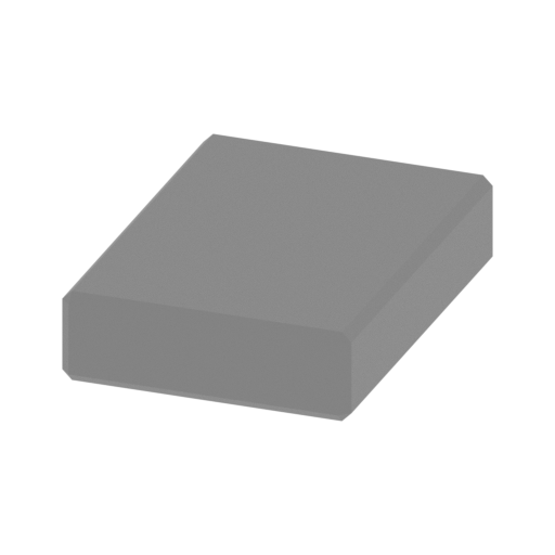 | _01_pin_x14_FDM (repaired).stl 15 x 20.8 x 4.8 mm | 0.59 x 0.82 x 0.19 in | Size: 15 x 20.8 x 4.8 mm | 0.59 x 0.82 x 0.19 in | File size: 0.01 mb | Printing Time / Filament: 3 min / <1 m Slicer: prusa v2.9.2 Printer: mk4s Non default settings Layer height: 0.2 Support material: 0 | ||
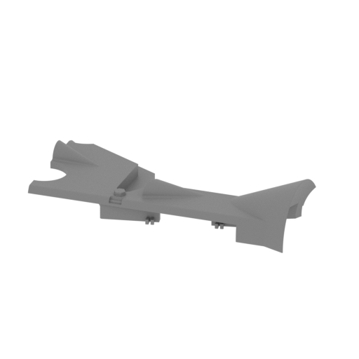 | _02_body_a_R_FDM (repaired).stl 216.2 x 119 x 42 mm | 8.51 x 4.69 x 1.65 in | Size: 216.2 x 119 x 42 mm | 8.51 x 4.69 x 1.65 in | File size: 32.75 mb | Printing Time / Filament: 2 h 28 min / 25 m Slicer: prusa v2.9.2 Printer: mk4s Non default settings Layer height: 0.2 Support material: 0 | ||
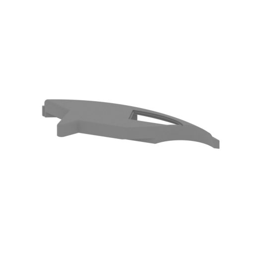 | _03_body_b_R_FDM (repaired).stl 286.8 x 114.1 x 28 mm | 11.29 x 4.49 x 1.1 in | Size: 286.8 x 114.1 x 28 mm | 11.29 x 4.49 x 1.1 in | File size: 41.43 mb | Printing Time / Filament: 4 h 14 min / 44 m Slicer: prusa v2.9.2 Printer: prusa_xl Non default settings Layer height: 0.2 Fill density: 20% Support material: 1 Support material buildplate only: 1 | ||
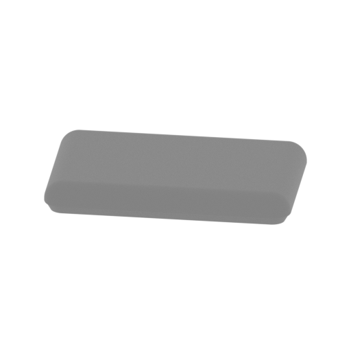 | _04_seat_a_FDM (repaired).stl 34.6 x 25.4 x 4 mm | 1.36 x 1 x 0.16 in | Size: 34.6 x 25.4 x 4 mm | 1.36 x 1 x 0.16 in | File size: 3.96 mb | Printing Time / Filament: 4 min / 1 m Slicer: prusa v2.9.2 Printer: mk4s Non default settings Layer height: 0.2 Support material: 0 | ||
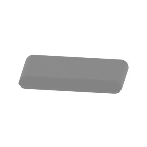 | _05_seat_b_FDM (repaired).stl 35.4 x 25.6 x 4 mm | 1.39 x 1.01 x 0.16 in | Size: 35.4 x 25.6 x 4 mm | 1.39 x 1.01 x 0.16 in | File size: 4.50 mb | Printing Time / Filament: 4 min / 1 m Slicer: prusa v2.9.2 Printer: mk4s Non default settings Layer height: 0.2 Support material: 0 | ||
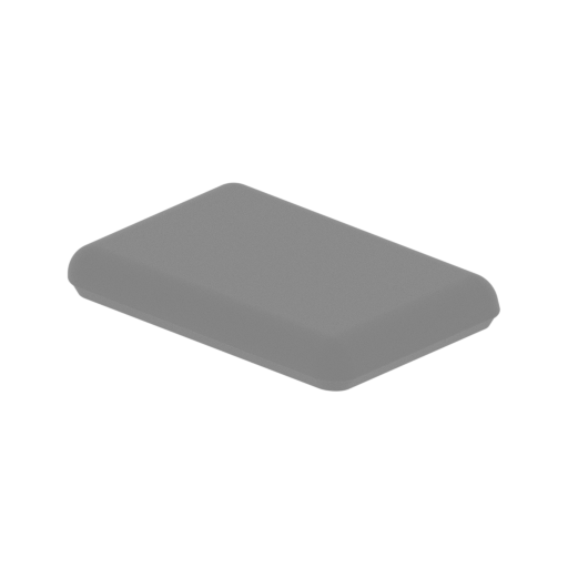 | _06_seat_c_FDM (repaired).stl 33.5 x 28.2 x 4 mm | 1.32 x 1.11 x 0.16 in | Size: 33.5 x 28.2 x 4 mm | 1.32 x 1.11 x 0.16 in | File size: 4.29 mb | Printing Time / Filament: 4 min / 1 m Slicer: prusa v2.9.2 Printer: mk4s Non default settings Layer height: 0.2 Support material: 0 | ||
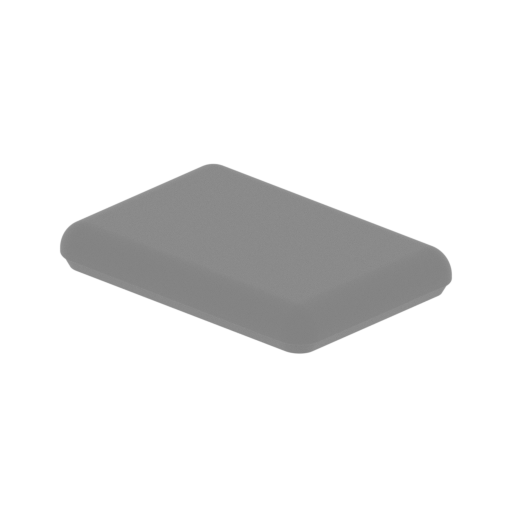 | _07_seat_d_FDM (repaired).stl 32.8 x 27.9 x 4 mm | 1.29 x 1.1 x 0.16 in | Size: 32.8 x 27.9 x 4 mm | 1.29 x 1.1 x 0.16 in | File size: 3.83 mb | Printing Time / Filament: 4 min / 1 m Slicer: prusa v2.9.2 Printer: mk4s Non default settings Layer height: 0.2 Support material: 0 | ||
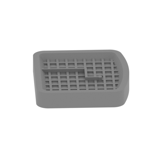 | _08_screen_FDM (repaired).stl 37.8 x 40.2 x 5.6 mm | 1.49 x 1.58 x 0.22 in | Size: 37.8 x 40.2 x 5.6 mm | 1.49 x 1.58 x 0.22 in | File size: 0.35 mb | Printing Time / Filament: 8 min / 1 m Slicer: prusa v2.9.2 Printer: mk4s Non default settings Layer height: 0.2 Support material: 0 | ||
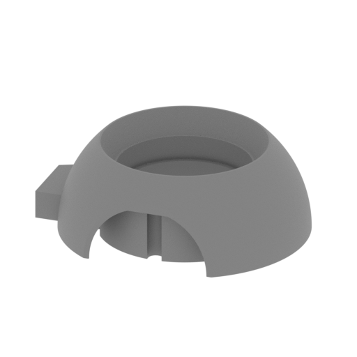 Updated Updated | _09_wheel_front_cover_R_FDM (repaired).stl 123.6 x 105.5 x 42 mm | 4.87 x 4.15 x 1.65 in | Size: 123.6 x 105.5 x 42 mm | 4.87 x 4.15 x 1.65 in | File size: 4.32 mb | Printing Time / Filament: 1 h 53 min / 23 m Slicer: prusa v2.9.2 Printer: mk4s Non default settings Layer height: 0.2 Support material: 0 | ||
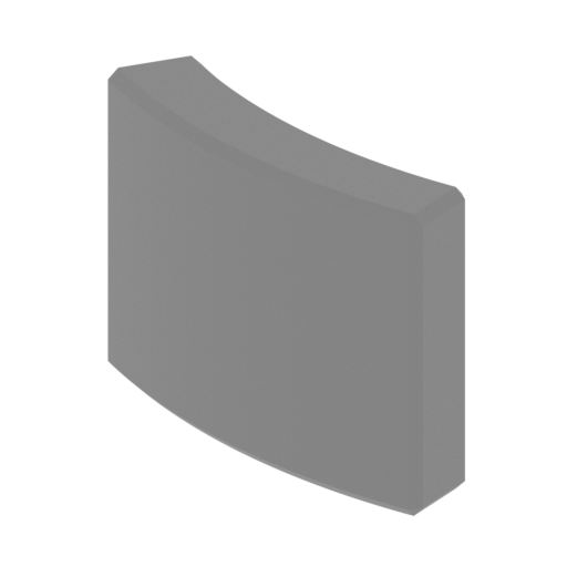 | _10_wheel_cover_front_pin_x3_FDM (repaired).stl 19.8 x 13.7 x 15 mm | 0.78 x 0.54 x 0.59 in | Size: 19.8 x 13.7 x 15 mm | 0.78 x 0.54 x 0.59 in | File size: 0.11 mb | Printing Time / Filament: 8 min / <1 m Slicer: prusa v2.9.2 Printer: mk4s Non default settings Layer height: 0.2 Support material: 0 | ||
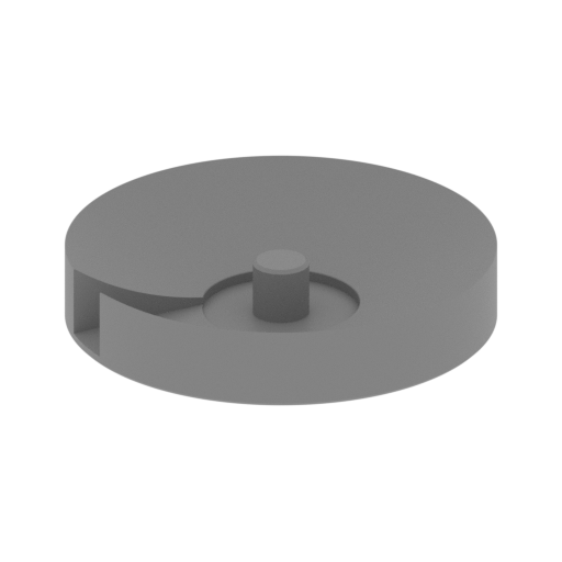 | _11_front_wheel_glass_x2_FDM (repaired).stl 61.1 x 61.1 x 11.4 mm | 2.41 x 2.41 x 0.45 in | Size: 61.1 x 61.1 x 11.4 mm | 2.41 x 2.41 x 0.45 in | File size: 4.18 mb | Printing Time / Filament: 19 min / 4 m Slicer: prusa v2.9.2 Printer: mk4s Non default settings Layer height: 0.2 Support material: 0 | ||
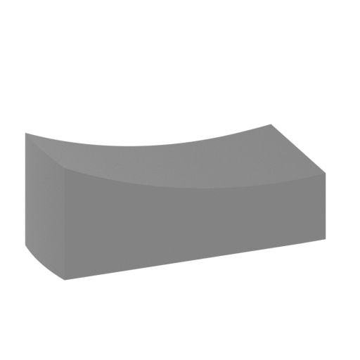 | _12_front_wheel_cap_holder_x2_FDM (repaired).stl 25 x 25 x 11.3 mm | 0.98 x 0.98 x 0.44 in | Size: 25 x 25 x 11.3 mm | 0.98 x 0.98 x 0.44 in | File size: 0.07 mb | Printing Time / Filament: 6 min / <1 m Slicer: prusa v2.9.2 Printer: mk4s Non default settings Layer height: 0.2 Support material: 0 | ||
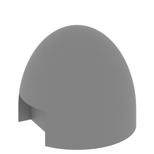 | _13_front_wheel_cap_x2_FDM (repaired).stl 22 x 22 x 19.8 mm | 0.87 x 0.87 x 0.78 in | Size: 22 x 22 x 19.8 mm | 0.87 x 0.87 x 0.78 in | File size: 6.29 mb | Printing Time / Filament: 11 min / 1 m Slicer: prusa v2.9.2 Printer: mk4s Non default settings Layer height: 0.2 Support material: 0 | ||
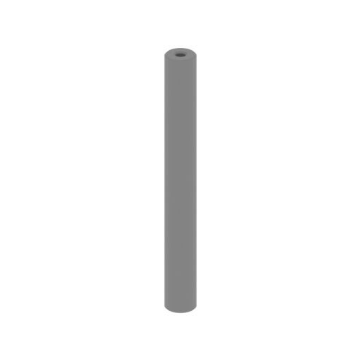 | _14_roller_wheel_front_x6_FDM (repaired).stl 6 x 6 x 52 mm | 0.24 x 0.24 x 2.05 in | Size: 6 x 6 x 52 mm | 0.24 x 0.24 x 2.05 in | File size: 2.03 mb | Printing Time / Filament: 12 min / 1 m Slicer: prusa v2.9.2 Printer: mk4s Non default settings Layer height: 0.2 Support material: 0 | ||
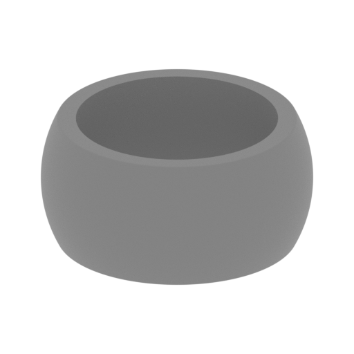 | _15_tire_front_FDM (repaired).stl 109.5 x 109.5 x 52 mm | 4.31 x 4.31 x 2.05 in | Size: 109.5 x 109.5 x 52 mm | 4.31 x 4.31 x 2.05 in | File size: 12.77 mb | Printing Time / Filament: 1 h 39 min / 23 m Slicer: prusa v2.9.2 Printer: mk4s Non default settings Layer height: 0.2 Support material: 0 | ||
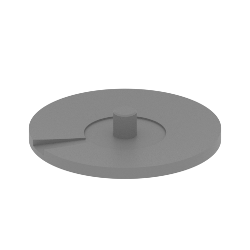 | _16_back_wheel_glass_x2_FDM (repaired).stl 65.8 x 65.8 x 10.8 mm | 2.59 x 2.59 x 0.43 in | Size: 65.8 x 65.8 x 10.8 mm | 2.59 x 2.59 x 0.43 in | File size: 1.84 mb | Printing Time / Filament: 22 min / 3 m Slicer: prusa v2.9.2 Printer: mk4s Non default settings Layer height: 0.2 Support material: 0 | ||
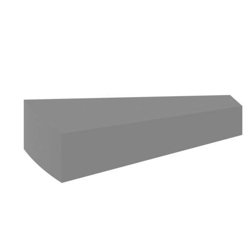 | _17_back_wheel_cap_holder_x2_FDM (repaired).stl 20.6 x 20.6 x 5.8 mm | 0.81 x 0.81 x 0.23 in | Size: 20.6 x 20.6 x 5.8 mm | 0.81 x 0.81 x 0.23 in | File size: 0.01 mb | Printing Time / Filament: 3 min / <1 m Slicer: prusa v2.9.2 Printer: mk4s Non default settings Layer height: 0.2 Support material: 0 | ||
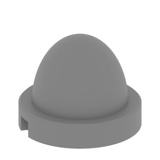 | _18_back_wheel_cap_x2_FDM (repaired).stl 28 x 28 x 21.7 mm | 1.1 x 1.1 x 0.85 in | Size: 28 x 28 x 21.7 mm | 1.1 x 1.1 x 0.85 in | File size: 6.70 mb | Printing Time / Filament: 13 min / 1 m Slicer: prusa v2.9.2 Printer: mk4s Non default settings Layer height: 0.2 Support material: 0 | ||
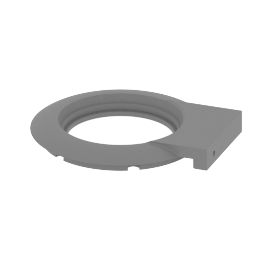 | _19_wheel_back_cover_R_FDM (repaired).stl 114.6 x 104.2 x 13.2 mm | 4.51 x 4.1 x 0.52 in | Size: 114.6 x 104.2 x 13.2 mm | 4.51 x 4.1 x 0.52 in | File size: 14.91 mb | Printing Time / Filament: 56 min / 9 m Slicer: prusa v2.9.2 Printer: mk4s Non default settings Layer height: 0.2 Support material: 0 | ||
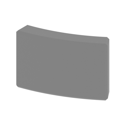 | _20_wheel_cover_back_pin_x3_FDM (repaired).stl 21.6 x 5.7 x 13.8 mm | 0.85 x 0.22 x 0.54 in | Size: 21.6 x 5.7 x 13.8 mm | 0.85 x 0.22 x 0.54 in | File size: 0.10 mb | Printing Time / Filament: 7 min / <1 m Slicer: prusa v2.9.2 Printer: mk4s Non default settings Layer height: 0.2 Support material: 0 | ||
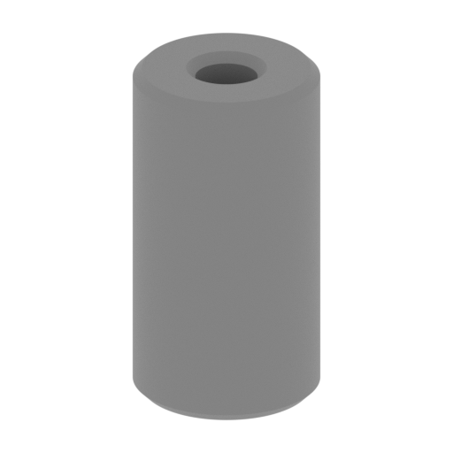 | _21_roller_wheel_back_x6_FDM (repaired).stl 6 x 6 x 11.1 mm | 0.24 x 0.24 x 0.44 in | Size: 6 x 6 x 11.1 mm | 0.24 x 0.24 x 0.44 in | File size: 0.53 mb | Printing Time / Filament: 3 min / <1 m Slicer: prusa v2.9.2 Printer: mk4s Non default settings Layer height: 0.2 Support material: 0 | ||
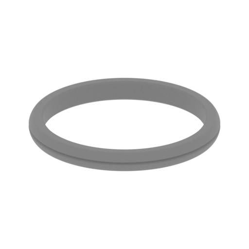 | _22_tire_back_FDM (repaired).stl 110.4 x 110.4 x 11.7 mm | 4.35 x 4.35 x 0.46 in | Size: 110.4 x 110.4 x 11.7 mm | 4.35 x 4.35 x 0.46 in | File size: 8.41 mb | Printing Time / Filament: 27 min / 5 m Slicer: prusa v2.9.2 Printer: mk4s Non default settings Layer height: 0.2 Support material: 0 | ||
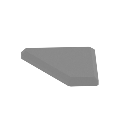 | _23_cockpit_led_R_FDM (repaired).stl 23.4 x 20.4 x 2 mm | 0.92 x 0.8 x 0.08 in | Size: 23.4 x 20.4 x 2 mm | 0.92 x 0.8 x 0.08 in | File size: 0.27 mb | Printing Time / Filament: 2 min / <1 m Slicer: prusa v2.9.2 Printer: mk4s Non default settings Layer height: 0.2 Support material: 0 | ||
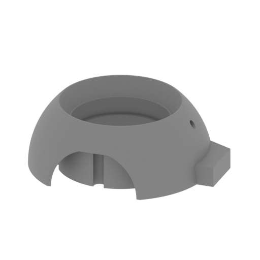 Updated Updated | _24_wheel_front_cover_L_FDM (repaired).stl 123.6 x 105.5 x 42 mm | 4.87 x 4.15 x 1.65 in | Size: 123.6 x 105.5 x 42 mm | 4.87 x 4.15 x 1.65 in | File size: 4.32 mb | Printing Time / Filament: 1 h 53 min / 23 m Slicer: prusa v2.9.2 Printer: mk4s Non default settings Layer height: 0.2 Support material: 0 | ||
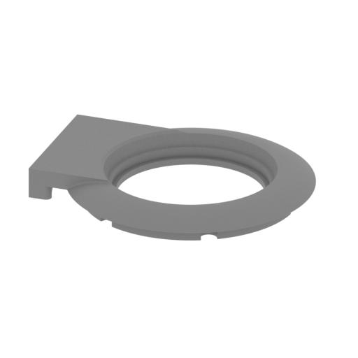 | _25_wheel_back_cover_L_FDM (repaired).stl 114.6 x 104.2 x 13.2 mm | 4.51 x 4.1 x 0.52 in | Size: 114.6 x 104.2 x 13.2 mm | 4.51 x 4.1 x 0.52 in | File size: 14.91 mb | Printing Time / Filament: 56 min / 9 m Slicer: prusa v2.9.2 Printer: mk4s Non default settings Layer height: 0.2 Support material: 0 | ||
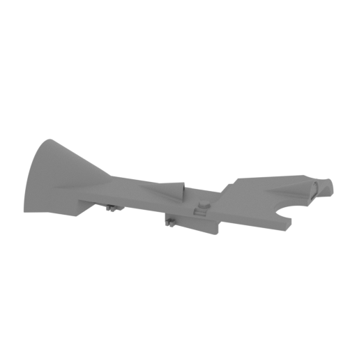 | _26_body_a_L_FDM (repaired).stl 216.2 x 119 x 42 mm | 8.51 x 4.69 x 1.65 in | Size: 216.2 x 119 x 42 mm | 8.51 x 4.69 x 1.65 in | File size: 32.93 mb | Printing Time / Filament: 2 h 27 min / 25 m Slicer: prusa v2.9.2 Printer: mk4s Non default settings Layer height: 0.2 Support material: 0 | ||
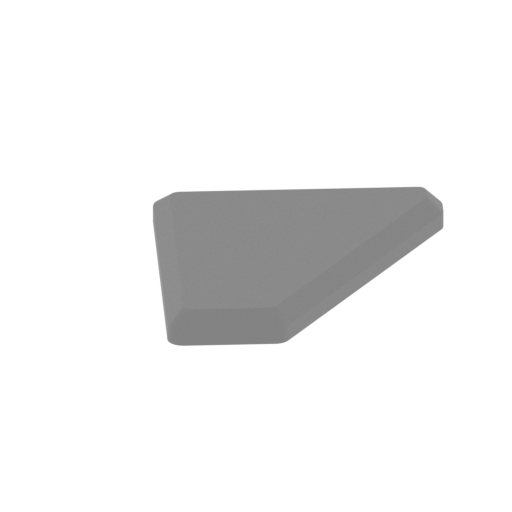 | _27_cockpit_led_L_FDM (repaired).stl 17.2 x 24.3 x 2 mm | 0.68 x 0.96 x 0.08 in | Size: 17.2 x 24.3 x 2 mm | 0.68 x 0.96 x 0.08 in | File size: 0.26 mb | Printing Time / Filament: 2 min / <1 m Slicer: prusa v2.9.2 Printer: mk4s Non default settings Layer height: 0.2 Support material: 0 | ||
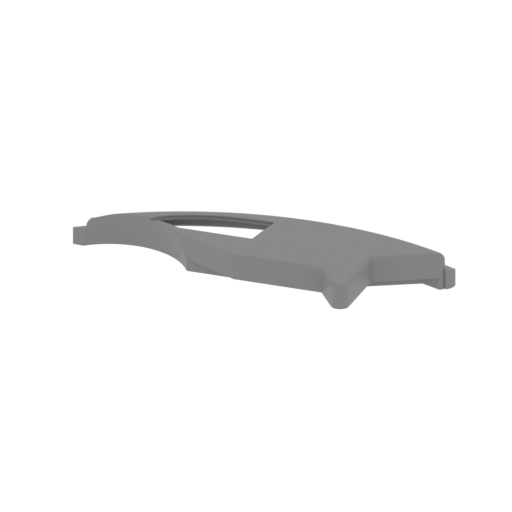 | _28_body_b_L_FDM (repaired).stl 286.8 x 114.1 x 28 mm | 11.29 x 4.49 x 1.1 in | Size: 286.8 x 114.1 x 28 mm | 11.29 x 4.49 x 1.1 in | File size: 41.43 mb | Printing Time / Filament: 4 h 13 min / 44 m Slicer: prusa v2.9.2 Printer: prusa_xl Non default settings Layer height: 0.2 Fill density: 20% Support material: 1 Support material buildplate only: 1 | ||
 | _29_handlebar_FDM (repaired).stl 5 x 5 x 60 mm | 0.2 x 0.2 x 2.36 in | Size: 5 x 5 x 60 mm | 0.2 x 0.2 x 2.36 in | File size: 3.27 mb | Printing Time / Filament: 11 min / <1 m Slicer: prusa v2.9.2 Printer: mk4s Non default settings Layer height: 0.2 Support material: 0 | ||
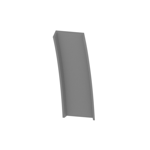 | _30_front_glass_FDM (repaired).stl 37.2 x 55.9 x 107.1 mm | 1.46 x 2.2 x 4.22 in | Size: 37.2 x 55.9 x 107.1 mm | 1.46 x 2.2 x 4.22 in | File size: 0.22 mb | Printing Time / Filament: 52 min / 3 m Slicer: prusa v2.9.2 Printer: mk4s Non default settings Layer height: 0.2 Support material: 0 | ||
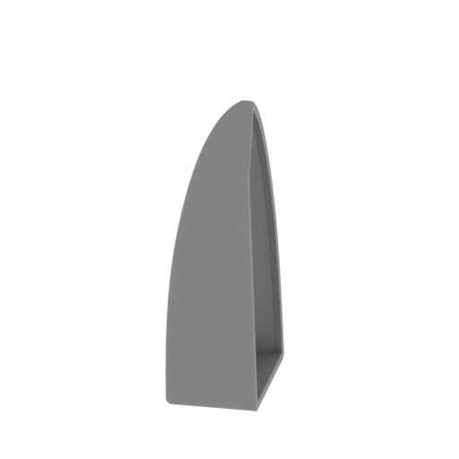 | _31_glass_R_FDM (repaired).stl 23.8 x 45.2 x 83.4 mm | 0.94 x 1.78 x 3.28 in | Size: 23.8 x 45.2 x 83.4 mm | 0.94 x 1.78 x 3.28 in | File size: 20.49 mb | Printing Time / Filament: 42 min / 4 m Slicer: prusa v2.9.2 Printer: mk4s Non default settings Layer height: 0.2 Support material: 0 | ||
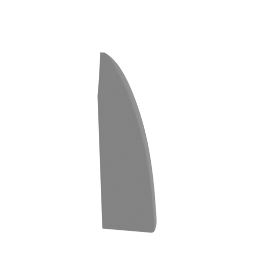 | _32_glass_L_FDM (repaired).stl 26.6 x 42.9 x 83.4 mm | 1.05 x 1.69 x 3.28 in | Size: 26.6 x 42.9 x 83.4 mm | 1.05 x 1.69 x 3.28 in | File size: 20.49 mb | Printing Time / Filament: 42 min / 4 m Slicer: prusa v2.9.2 Printer: mk4s Non default settings Layer height: 0.2 Support material: 0 | ||
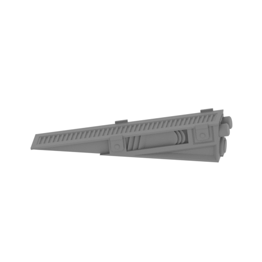 | _33_engine_FDM (repaired).stl 104 x 37.3 x 22.4 mm | 4.09 x 1.47 x 0.88 in | Size: 104 x 37.3 x 22.4 mm | 4.09 x 1.47 x 0.88 in | File size: 10.10 mb | Printing Time / Filament: 33 min / 3 m Slicer: prusa v2.9.2 Printer: mk4s Non default settings Layer height: 0.2 Support material: 0 | ||
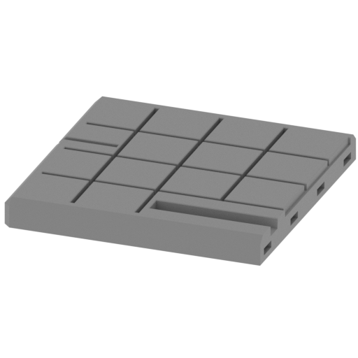 | _34_stand_1_FDM (repaired).stl 180 x 180 x 20 mm | 7.09 x 7.09 x 0.79 in | Size: 180 x 180 x 20 mm | 7.09 x 7.09 x 0.79 in | File size: 0.91 mb | Printing Time / Filament: 4 h 13 min / 66 m Slicer: prusa v2.9.2 Printer: mk4s Non default settings Layer height: 0.2 Support material: 0 | ||
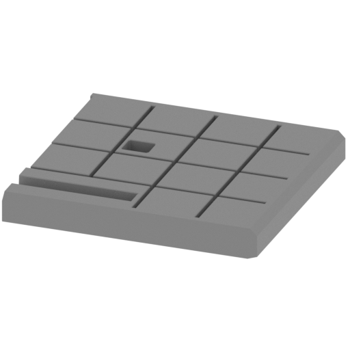 | _35_stand_2_FDM (repaired).stl 180 x 180 x 20 mm | 7.09 x 7.09 x 0.79 in | Size: 180 x 180 x 20 mm | 7.09 x 7.09 x 0.79 in | File size: 0.17 mb | Printing Time / Filament: 4 h 3 min / 66 m Slicer: prusa v2.9.2 Printer: mk4s Non default settings Layer height: 0.2 Support material: 0 | ||
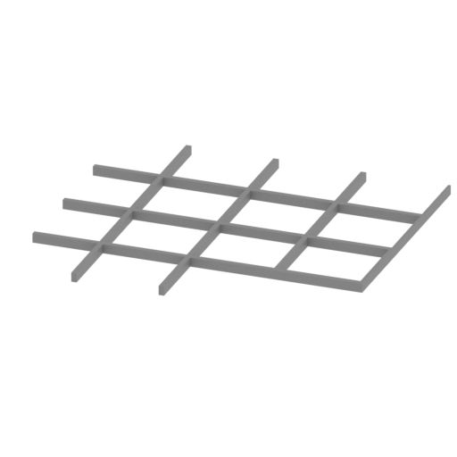 | _36_Grid_1_FDM (repaired).stl 169.8 x 159.8 x 4.8 mm | 6.69 x 6.29 x 0.19 in | Size: 169.8 x 159.8 x 4.8 mm | 6.69 x 6.29 x 0.19 in | File size: 0.06 mb | Printing Time / Filament: 25 min / 5 m Slicer: prusa v2.9.2 Printer: mk4s Non default settings Layer height: 0.2 Support material: 0 | ||
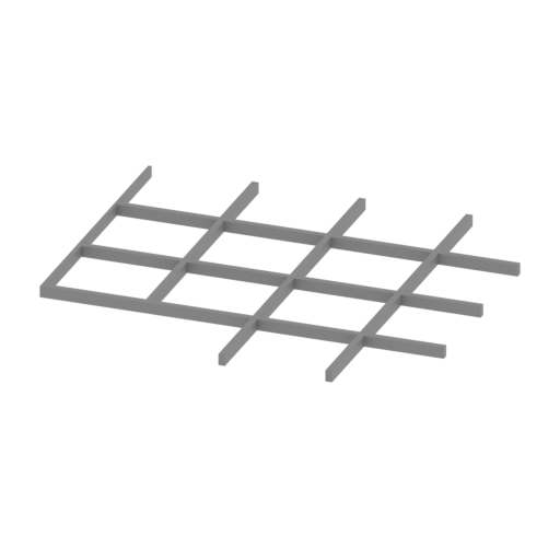 | _37_Grid_2_FDM (repaired).stl 169.9 x 159.8 x 4.8 mm | 6.69 x 6.29 x 0.19 in | Size: 169.9 x 159.8 x 4.8 mm | 6.69 x 6.29 x 0.19 in | File size: 0.06 mb | Printing Time / Filament: 25 min / 5 m Slicer: prusa v2.9.2 Printer: mk4s Non default settings Layer height: 0.2 Support material: 0 | ||
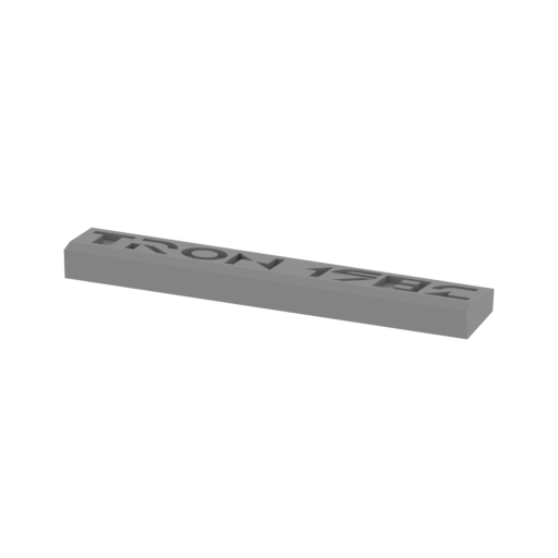 | _38_Logo_FDM (repaired).stl 169 x 31.4 x 13.3 mm | 6.65 x 1.24 x 0.52 in | Size: 169 x 31.4 x 13.3 mm | 6.65 x 1.24 x 0.52 in | File size: 0.46 mb | Printing Time / Filament: 54 min / 9 m Slicer: prusa v2.9.2 Printer: mk4s Non default settings Layer height: 0.2 Support material: 0 | ||
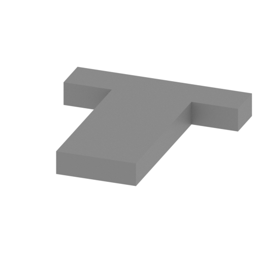 | _39_Letter_T_FDM (repaired).stl 16.9 x 18.2 x 2.3 mm | 0.67 x 0.72 x 0.09 in | Size: 16.9 x 18.2 x 2.3 mm | 0.67 x 0.72 x 0.09 in | File size: 0.00 mb | Printing Time / Filament: 2 min / <1 m Slicer: prusa v2.9.2 Printer: mk4s Non default settings Layer height: 0.2 Support material: 0 | ||
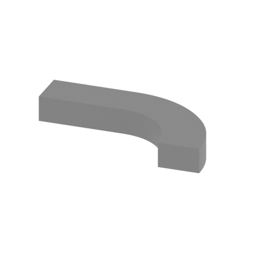 | _40_Letter_R_a_FDM (repaired).stl 16.5 x 9.1 x 2.3 mm | 0.65 x 0.36 x 0.09 in | Size: 16.5 x 9.1 x 2.3 mm | 0.65 x 0.36 x 0.09 in | File size: 0.06 mb | Printing Time / Filament: 1 min / <1 m Slicer: prusa v2.9.2 Printer: mk4s Non default settings Layer height: 0.2 Support material: 0 | ||
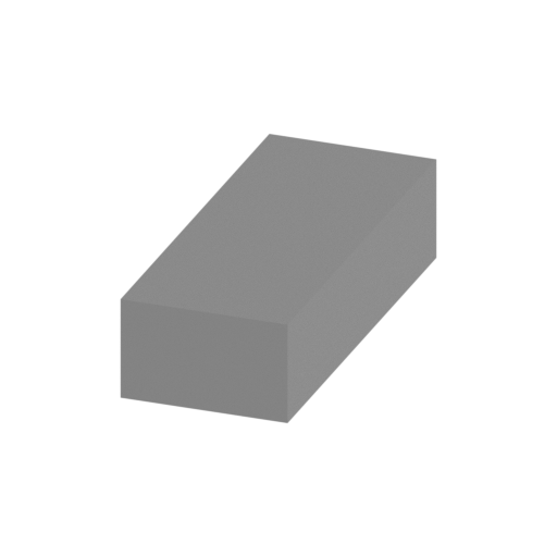 | _41_Letter_R_b_FDM (repaired).stl 3.7 x 9 x 2.3 mm | 0.15 x 0.35 x 0.09 in | Size: 3.7 x 9 x 2.3 mm | 0.15 x 0.35 x 0.09 in | File size: 0.00 mb | Printing Time / Filament: 1 min / <1 m Slicer: prusa v2.9.2 Printer: mk4s Non default settings Layer height: 0.2 Support material: 0 | ||
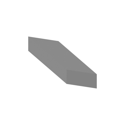 | _42_Letter_R_c_FDM (repaired).stl 13.9 x 9 x 2.3 mm | 0.55 x 0.35 x 0.09 in | Size: 13.9 x 9 x 2.3 mm | 0.55 x 0.35 x 0.09 in | File size: 0.00 mb | Printing Time / Filament: 1 min / <1 m Slicer: prusa v2.9.2 Printer: mk4s Non default settings Layer height: 0.2 Support material: 0 | ||
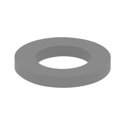 | _43_Letter_O_FDM (repaired).stl 18.2 x 18.2 x 2.3 mm | 0.72 x 0.72 x 0.09 in | Size: 18.2 x 18.2 x 2.3 mm | 0.72 x 0.72 x 0.09 in | File size: 0.23 mb | Printing Time / Filament: 2 min / <1 m Slicer: prusa v2.9.2 Printer: mk4s Non default settings Layer height: 0.2 Support material: 0 | ||
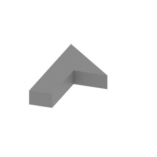 | _44_Letter_N_a_FDM (repaired).stl 9.1 x 18 x 2.3 mm | 0.36 x 0.71 x 0.09 in | Size: 9.1 x 18 x 2.3 mm | 0.36 x 0.71 x 0.09 in | File size: 0.00 mb | Printing Time / Filament: 1 min / <1 m Slicer: prusa v2.9.2 Printer: mk4s Non default settings Layer height: 0.2 Support material: 0 | ||
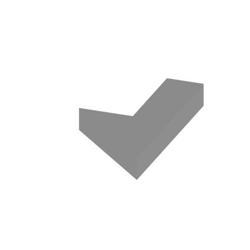 | _45_Letter_N_b_FDM (repaired).stl 9.1 x 18 x 2.3 mm | 0.36 x 0.71 x 0.09 in | Size: 9.1 x 18 x 2.3 mm | 0.36 x 0.71 x 0.09 in | File size: 0.00 mb | Printing Time / Filament: 1 min / <1 m Slicer: prusa v2.9.2 Printer: mk4s Non default settings Layer height: 0.2 Support material: 0 | ||
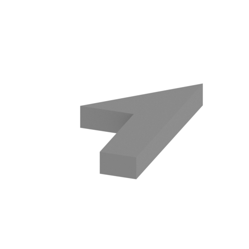 | _46_Letter_1_FDM (repaired).stl 9.1 x 18 x 2.3 mm | 0.36 x 0.71 x 0.09 in | Size: 9.1 x 18 x 2.3 mm | 0.36 x 0.71 x 0.09 in | File size: 0.00 mb | Printing Time / Filament: 1 min / <1 m Slicer: prusa v2.9.2 Printer: mk4s Non default settings Layer height: 0.2 Support material: 0 | ||
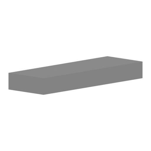 | _47_Letter_9_a_FDM (repaired).stl 14.4 x 9 x 2.3 mm | 0.57 x 0.35 x 0.09 in | Size: 14.4 x 9 x 2.3 mm | 0.57 x 0.35 x 0.09 in | File size: 0.00 mb | Printing Time / Filament: 1 min / <1 m Slicer: prusa v2.9.2 Printer: mk4s Non default settings Layer height: 0.2 Support material: 0 | ||
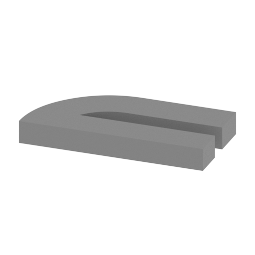 | _48_Letter_9_b_FDM (repaired).stl 18.5 x 9 x 2.3 mm | 0.73 x 0.35 x 0.09 in | Size: 18.5 x 9 x 2.3 mm | 0.73 x 0.35 x 0.09 in | File size: 0.05 mb | Printing Time / Filament: 2 min / <1 m Slicer: prusa v2.9.2 Printer: mk4s Non default settings Layer height: 0.2 Support material: 0 | ||
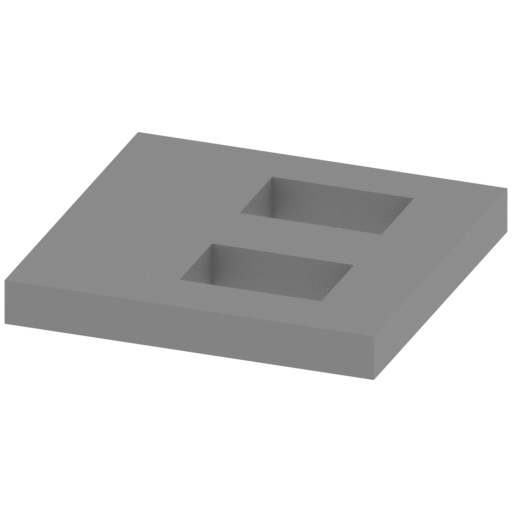 | _49_Letter_8_FDM (repaired).stl 18.7 x 18.2 x 2.3 mm | 0.74 x 0.72 x 0.09 in | Size: 18.7 x 18.2 x 2.3 mm | 0.74 x 0.72 x 0.09 in | File size: 0.01 mb | Printing Time / Filament: 2 min / <1 m Slicer: prusa v2.9.2 Printer: mk4s Non default settings Layer height: 0.2 Support material: 0 | ||
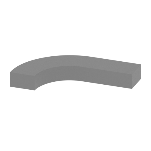 | _50_Letter_2_a_FDM (repaired).stl 16.5 x 9 x 2.3 mm | 0.65 x 0.35 x 0.09 in | Size: 16.5 x 9 x 2.3 mm | 0.65 x 0.35 x 0.09 in | File size: 0.06 mb | Printing Time / Filament: 1 min / <1 m Slicer: prusa v2.9.2 Printer: mk4s Non default settings Layer height: 0.2 Support material: 0 | ||
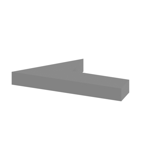 | _51_Letter_2_b_FDM (repaired).stl 18.8 x 8.8 x 2.3 mm | 0.74 x 0.35 x 0.09 in | Size: 18.8 x 8.8 x 2.3 mm | 0.74 x 0.35 x 0.09 in | File size: 0.00 mb | Printing Time / Filament: 1 min / <1 m Slicer: prusa v2.9.2 Printer: mk4s Non default settings Layer height: 0.2 Support material: 0 | ||
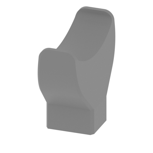 | _52_Bike_holder_FDM (repaired).stl 19 x 44 x 38.6 mm | 0.75 x 1.73 x 1.52 in | Size: 19 x 44 x 38.6 mm | 0.75 x 1.73 x 1.52 in | File size: 1.48 mb | Printing Time / Filament: 23 min / 2 m Slicer: prusa v2.9.2 Printer: mk4s Non default settings Layer height: 0.2 Support material: 0 | ||
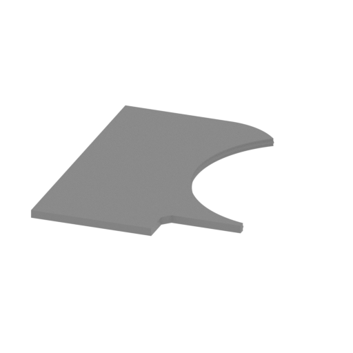 | _53_Light_line_FDM (repaired).stl 101.5 x 131.4 x 4 mm | 4 x 5.17 x 0.16 in | Size: 101.5 x 131.4 x 4 mm | 4 x 5.17 x 0.16 in | File size: 1.04 mb | Printing Time / Filament: 31 min / 8 m Slicer: prusa v2.9.2 Printer: mk4s Non default settings Layer height: 0.2 Support material: 0 | ||
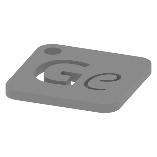 | Keychain (repaired).stl 29.7 x 29.7 x 2.4 mm | 1.17 x 1.17 x 0.09 in | Size: 29.7 x 29.7 x 2.4 mm | 1.17 x 1.17 x 0.09 in | File size: 0.37 mb | Printing Time / Filament: 6 min / 1 m Slicer: prusa v2.9.2 Printer: mk4s Non default settings Layer height: 0.2 Support material: 0 | ||
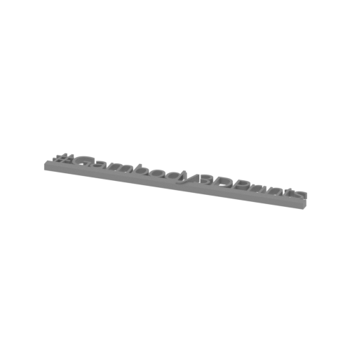 | Tag (repaired).stl 150.1 x 18.2 x 4.6 mm | 5.91 x 0.72 x 0.18 in | Size: 150.1 x 18.2 x 4.6 mm | 5.91 x 0.72 x 0.18 in | File size: 1.78 mb | Printing Time / Filament: 16 min / 2 m Slicer: prusa v2.9.2 Printer: mk4s Non default settings Layer height: 0.2 Support material: 0 | ||
 Updated Updated | _54_front wheel pin x6(instead filament).stl 1.7 x 1.8 x 58 mm | 0.07 x 0.07 x 2.28 in | Size: 1.7 x 1.8 x 58 mm | 0.07 x 0.07 x 2.28 in | File size: 0.07 mb | Printing Time / Filament: 3 min / <1 m Slicer: prusa v2.9.2 Printer: prusa_xl Non default settings Layer height: 0.2 Fill density: 20% Support material: 1 Support material buildplate only: 1 | ||
3D model history
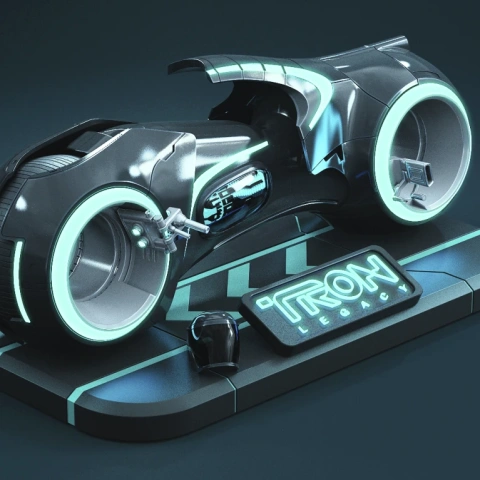
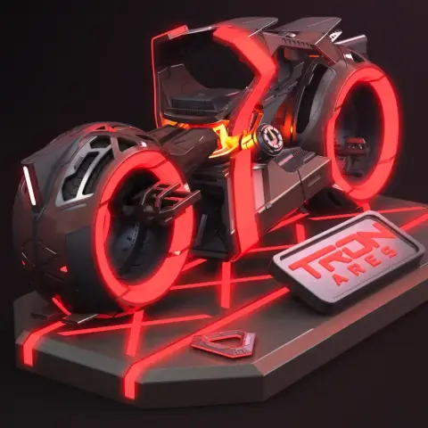
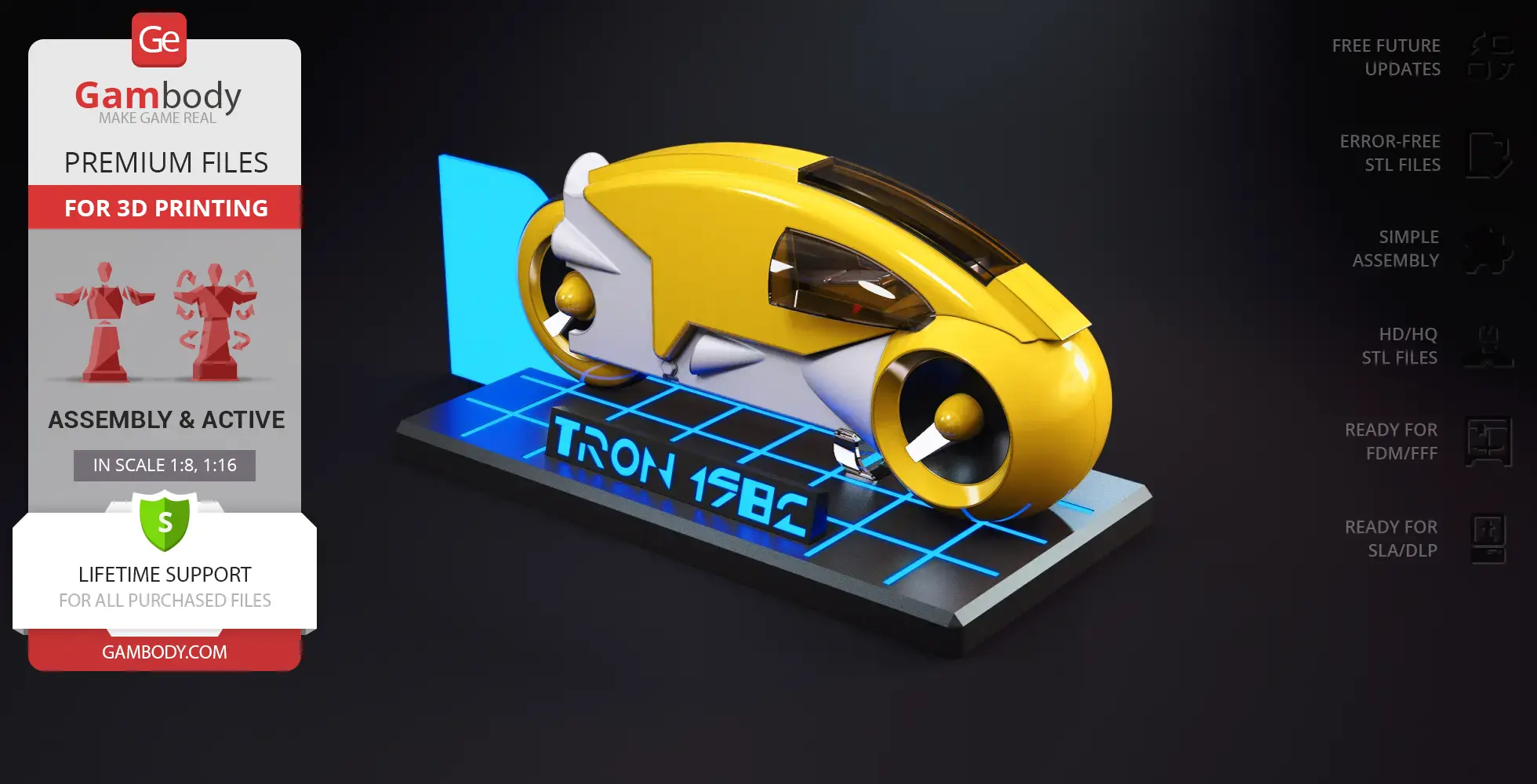
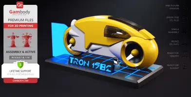
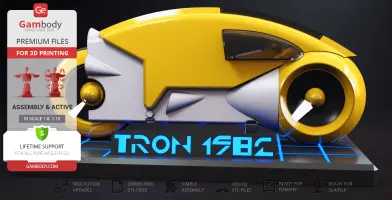
In TRON 1982, industrial designer Syd Mead took the classic motorcycle silhouette and transformed it into something raw, graphic, and completely unique. Built for the high-stakes matches of the Game Grid, these enclosed machines forced riders into a low, forward-leaning stance as they raced across dark digital arenas at blinding speeds. Bound by rigid physics, they made sharp right-angle turns and left lethal, solid walls of light in their wake. Decades later, the 1st generation TRON bike remains a defining piece of sci-fi history, standing apart from the TRON Ares Light Cycle and the later TRON Legacy Light Cycle with its clean lines and retro-futuristic character.
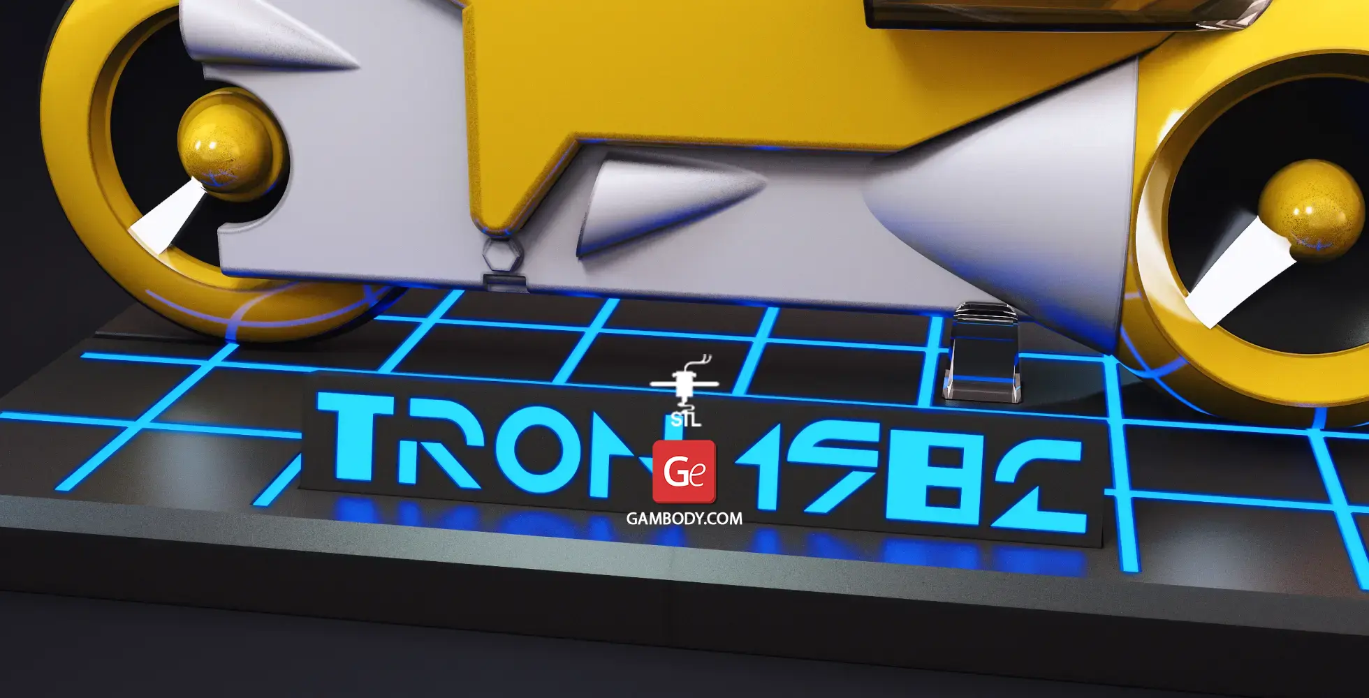
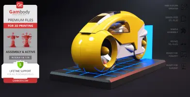
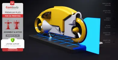
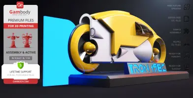
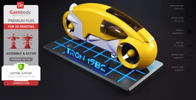
This TRON 1982 Light Cycle 3D model brings that graphic aesthetic into the physical world with practical, maker-focused features. The build includes smooth rotating wheels mounted on bearings and a removable bottom engine section for clean access to the battery compartment. For those looking to light up their display, the FDM-adapted version offers internal space for optional LED illumination in the wheels and cockpit, along with an optional printable light ribbon. The display base also gives you creative freedom: you can print the individual lettering and grid inserts, or leave the cavities empty and fill them with fluorescent paint for a glowing effect. Whether you build the streamlined SLA version or go with a full 3D printed motorcycle in FDM, this project is a standout addition for collectors of vehicle 3D models and classic movie 3D models. Grab your bike STL files and bring the original Grid home!
3D printing model features
Model-specific features:
- Inspired by the iconic 1st generation Grid vehicle from the original 1982 TRON film.
- Features smoothly rotating wheels mounted on mechanical bearings.
- Designed with a removable bottom engine section for convenient access to the battery compartment (FFF/FDM only).
- Includes an optional printable light ribbon element trailing behind the vehicle for a dynamic display.
- Features internal routing and channels to support optional LED illumination for the front wheel, rear wheel, and cockpit (FFF/FDM only).
- Comes with a themed display base featuring recessed lettering and grid detailing.
- Offers versatile finishing options: base lettering and grid can be printed as separate insert pieces or left as open cavities to be filled with fluorescent paint (FFF/FDM only).
Printing & assembly details:
- Provided as error-free STL files compatible with most 3D printers;
- Optimized part division minimizes support material and ensures smooth and precise surface detailing;
- The assembly parts in the FFF/FDM version come in the recommended print orientations for easy bed placement;
- Assembly manual in PDF and video formats is included for the FFF/FDM and DLP/SLA versions;
- The model is available in recommended scales — 1:8 for the FFF/FDM version and 1:16 for the DLP/SLA versions.
What will you get after purchase?
- 2 versions of TRON 1982 Light CycleSTL files for FFF/FDM and DLP/SLA — files for all versions are available for download after the purchase;
- STL files of high-poly TRON 1982 Light Cycle model for 3D printing consist of 85 files;
- Sizes for:
- FFF/FDM Model Size: 96 mm wide, 174 mm high, 424 mm deep;
- FFF/FDM Platform Size: 180 mm wide, 44 mm high, 360 mm deep;
- DLP/SLA Model Size: 48 mm wide, 87 mm high, 212 mm deep;
- DLP/SLA Platform Size: 90 mm wide, 22 mm high, 180 mm deep;
- Assembly Manual for 1.0 FFF/FDM and 1.0 DLP/SLA versions in PDF and video formats;
- Detailed settings that we provide as a recommendation for Bambu Studio, Cura, Orca Slicer, PrusaSlicer, Simplify3D, and Slic3r for the best print;
- Full technical support from the Gambody Support Team.
Average customer rating (3 reviews)
4
Ratings breakdown
Click a star rating to filter reviews
Overall experience
Level of detail in the model
3.8
Model cut quality and assembly guide
3.5
Clarity and accuracy of the model page
4.2



 Verified purchase
 Level of detail in the model
3
Model cut quality and assembly guide
3
Clarity and accuracy of the model page
4
1. The holes for the connectors in baseplates 34 and 35 are too small. I had to resize parts 01x4 to be narrower to fit.
2. The cylinders for the big wheel are almost impossible to align and server no real purpose. I left them out entirely and the tire still spins just fine. The smaller wheel was easier to get lined up but still probably not needed. Also the instructions do not state how long the pieces of filament should be so I just had to guess.
3. I'm not sure why the three highlighted cutouts for connectors go all the way through parts 2 and 26. That makes it actually harder to glue in and it would just look better if they were recessed like the other two on those parts.


 Community Support Team
 We’ve reviewed your comments and would like to clarify a few points regarding the model’s design and assembly.
1. The connector holes in parts #34 and #35 have been designed with the necessary clearances, and our team has not identified any issues with their dimensions. Please see the attached image for reference.
However, small dimensional differences caused by printer calibration or over-extrusion can sometimes result in tighter-fitting connections. We recommend checking your printer’s flow settings and dimensional accuracy, as even minor deviations can affect the fit of closely connected parts.
2. We’re glad to hear that the wheels rotate smoothly in your finished build!
The additional rollers are intended to support the wheel assembly and help maintain its functionality, particularly when the model is printed at a larger scale, where the increased weight can place additional stress on the mechanism.
If you decide to install the rollers, you can also use the alternative printable pins instead of pieces of filament. You can find the STL file named _54_front wheel pin x6 (instead filament).stl on the model page in the Source Files tab, under the FFF/FDM printer type and 1.0 Initial model version.
3. The highlighted connector openings were designed to go all the way through parts #2 and #26 to avoid the need for additional supports during printing.
However, we understand your preference for recessed openings. If you would like to use this alternative configuration, please contact our Support Team at support@gambody.com, and we’ll be happy to assist with the modification.
Thank you again for sharing your experience and suggestions. We appreciate your attention to detail and hope you continue to enjoy your finished Light Cycle!
Verified purchase Level of detail in the model
4
Model cut quality and assembly guide
3
Clarity and accuracy of the model page
4
 Community Support Team
 To help save you time, we wanted to let you know that the parts provided for FFF/FDM printers in the "1.0 Initial" version are already pre-oriented in the recommended position, as chosen by our team. When you load those parts into your slicer, they are already set to the orientation that offers the best surface quality and requires the minimum amount of supports, so you generally don't need to guess which face goes on the build plate.
While our PDF guide focuses on assembly steps rather than print orientation, if you ever run into a specific part where the suggested position isn't working out for your setup, you are always welcome to experiment with alternative orientations or reach out to our support team with a photo so we can help you out.
Thanks again for taking the time to share your feedback!
 Verified purchase
 Level of detail in the model
4.5
Model cut quality and assembly guide
4.5
Clarity and accuracy of the model page
4.5
Community Support Team Thank you again for your help in improving the model!
Community Support Team Regarding the issue you noticed with the front wheel cover slot, thank you for pointing that out and sharing the photo. Our team is already looking into this right now to investigate the alignment, and we will get back to you as soon as possible with an update or a fix.
Thanks again for helping us improve the model!
Below you'll find detailed slicing settings for Bambu Studio 2.0+, Orca Slicer 2.0+, UltiMaker Cura 5.0+, PrusaSlicer 2.0+, Slic3r 1.3+, Simplify3D 5.0+ to help you get the best results when printing this model. These settings are optimized specifically for this 3D model, but please note they may need slight adjustments depending on your printer or filament. When in doubt, refer to your printer's user manual.
To avoid printing issues and achieve the best quality, we highly recommend applying the following settings:
 Bambu Studio 2.0+
 For better quality use 0.12 mm layer height, for fast printing use 0.2 mm layer height. For pins and the Ge connectors, use 0.2 layer height.
120-150% of your Layer Height
But you can paint the seam if you want.
You have to calibrate this parameter
You have to calibrate this parameter
You have to calibrate this parameter
For pins and power elements of the structure, such as the vehicle frame, use 3 loop
Disabled for vehicles and enabled for characters
For 0,2 Layer Height
The parameters in this tab vary greatly, it all depends on the quality of your printer. For example, if you have a classic Ender3, stick to the minimum parameters, but if you have a newer printer, for example Anycubic cobra 3 v2, you can select the maximum recommended values
Settings for advanced users, change these parameters only if you have sufficient 3D printing expertise
Enable this parameter if your model requires supports
We also recommend placing and removing supports manually in some places using special button
1-2 loops for more thick support
Top Z distance = 1-1.3 layer Height. If the supports are hard to remove, try increasing this setting by 0.1-0,4 mm
Bottom Z distance = 1-1.3 layer Height. If the supports are hard to remove, try increasing this setting by 0.1-0,4 mm
You have to calibrate this parameter which one is better for your filament
Increase this parameter if the supports are hard to remove from walls
For PLA and PETG filament types
5-8 mm is optional for small prints that have bad adhesion to the build plate
You have to calibrate this parameter
Read the description on your filament roll
Read the description on your filament roll and increase this parameter for fast printers
Read the description on your filament roll and increase this parameter for fast printers
 Orca Slicer 2.0+
 For better quality use 0.12 mm layer height, for fast printing use 0.2 mm layer height. For pins and the Ge connectors, use 0.2 layer height.
120-150% of your Layer Height
But you can paint the seam if you want.
0.01-0.05 You have to calibrate this parameter
0.01-0.05 You have to calibrate this parameter
0.1-0.2 You have to calibrate this parameter
For pins and power elements of the structure, such as the vehicle frame, use 3 loop
Disabled for vehicles and ships, enabled for characters
For 0,2 Layer Height
For 0,2 Layer Height
The parameters in this tab vary greatly, it all depends on the quality of your printer. For example, if you have a classic Ender3, stick to the minimum parameters, but if you have a newer printer, for example, Anycubic Kobra 3 Or Bambulab A1, you can select the maximum recommended values.
Settings for advanced users, change these parameters only if you have sufficient 3D printing expertise
Enable this parameter if your model requires supports
We also recommend placing and removing supports manually in some places using special button
Top Z distance = 1-1.3 layer Height. If the supports are hard to remove, try increasing this setting by 0.1-0,4 mm
Bottom Z distance = 1-1.3 layer Height. If the supports are hard to remove, try increasing this setting by 0.1-0,4 mm
Increase this parameter if the supports are hard to remove from walls
For PLA and PETG filament types
5-8 mm is optional for small prints that have bad adhesion to the build plate
Read the description on your filament roll
Read the description on your filament roll and increase this parameter for fast printers
You have to calibrate this parameter
Read the description on your filament roll and increase this parameter for fast printers
Read the description on your filament roll
This field is filled in according to your printer specifications when you add it to the slicer.
You can add custom G-code here for the start and end of the print. However, be careful - this is for advanced users only!
You have to calibrate your printer using Ge retraction test models
Retraction Length: For direct-drive setups use 0.5 mm to 2.5 mm; for Bowden extruders use 5 to 7 mm
This is how fast the filament is pulled back—40-60 mm/s for direct drive and 30-50 mm/s for Bowden setups.
You have to calibrate this parameter: Reduce it until the printer starts to hit the parts with the nozzle during printing, then increase it by 0.2.
 UltiMaker Cura 5.0+
 For better quality use 0.12 mm layer height, for fast printing use 0.2 mm layer height. For pins and the Ge connectors, use 0.2 layer height.
120-150% of your Layer Height
To increase the strength of the print parts, use wall line count: 3
For pins and connectors use 50% Infill
These parameters are for standard PLA plastic. If you are using a different type of plastic, check the printing temperature recommended by the manufacturer. Also, read the description on your filament spool. For fast printers, add +30 °C to the current parameters.
The parameters in this tab vary greatly, it all depends on the quality of your printer. For example, if you have a classic Ender3, stick to the minimum parameters, but if you have a newer printer, for example Anycubic cobra 3 v3, you can select the maximum recommended values
Settings for advanced users, change these parameters only if you have sufficient 3D printing expertise.
You need to calibrate this parameter using Gambody test models. These values are average values for a Direct Drive extruder; for a Bowden extruder, the values should be increased.
You need to calibrate this parameter using Gambody test models. These values are average values for a Direct Drive extruder; for a Bowden extruder, the values should be increased.
Use this value other than 0 if your nozzle catches on the internal infill during travel moves. Try to keep this value as low as possible in height.
Use normal supports to support large, straight surfaces (most mechanical or technical parts).
You have to calibrate this parameter according to the capabilities of your printer and your filament, using a Gambody test models.
Use 1 instead of 0 if your supports are thin and tall. They will be harder to remove, but much stronger.
Top Z distance = 1-1.3 layer Height. If the supports are hard to remove, try increasing this setting by 0.1-0,4 mm
Increase this parameter if the supports are hard to remove from walls
Use tree supports to support complex objects, such as characters.
You have to calibrate this parameter according to the capabilities of your printer and your filament, using a Gambody test models.
Top Z distance = 1-1.3 layer Height. If the supports are hard to remove, try increasing this setting by 0.1-0,4 mm
Increase this parameter if the supports are hard to remove from walls
Use a skirt for all parts when printing on outdated printers.
Use a brim when printing thin but tall parts, as well as parts with a small bed adhesion area.
 PrusaSlicer 2.0+
 For better quality use 0.12 mm layer height, for fast printing use 0.2 mm layer height. For pins and the Ge connectors, use 0.2 layer height.
120-150% of your Layer Height
for 0.2 Layer Height
But you can paint the seam if you want.
(for PLA and PETG)
(5-8 mm is optional for small prints that have bad adhesion to the build plate)
Enable this parameter if your model requires supports
(45-50 degree)You have to calibrate this parameter according to the capabilities of your printer
and your filament, using a Gambody test models.
Top contact Z distance = 1-1.3 layer Height. If the supports are hard to remove, try
increasing this setting by 0.1-0,4 mm
Top contact Z distance = 1-1.3 layer Height. If the supports are hard to remove, try
increasing this setting by 0.1-0,4 mm
Increase this parameter if the supports are hard to remove from walls
The parameters in this tab vary greatly, it all depends on the quality of your printer. For example, if you have a classic Ender3, stick to the minimum parameters, but if you have a newer printer, for example Anycubic cobra 3 v3, you can select the maximum recommended values
Settings for advanced users, change these parameters only if you have sufficient 3D printing expertise. Use the minimum value for outdated printers without acceleration calibration, and the maximum value for modern printers if you need it.
These settings only work for 3D printers with multiple extruders
You can try setting all parameters in this section, except the First layer, to values between 0.75% of your nozzle diameter and 1.25% of your nozzle diameter. Adjusting them will help you work out the optimal parameters for the best quality for your print. As for the First layer, you can set it to 150% of the diameter of your nozzle for better adhesion to the build plate (for a nozzle with a diameter of 0.4 mm, the First layer extrusion width can be from 0.3 mm to 0.5 mm)
For better printing quality you have to calibrate this parameter using Gambody test model.
Check your filament manufacturer's temperature recommendations on the spool.
Cooling parameters depends on the material you use for printing.
*for PLA
 Slic3r 1.3+
 For better quality use 0.12 mm layer height, for fast printing use 0.2 mm layer height. For pins and the Ge connectors, use 0.2 layer height.
120-150% of your Layer Height
For 0.12 Layer Height
For 0.12 Layer Height
For pins and connectors use 50% Infill
Use skirt for outdated 3d printers
(5-8 mm is optional for small prints that have bad adhesion to the build plate)
Enable this parameter if your model requires supports
(45-60 degree)You have to calibrate this parameter according to the capabilities of your printer and your filament, using a Gambody test models
Contact Z distance = 1-1.3 layer Height. If the supports are hard to remove, try increasing this setting by 0.1-0,4 mm
The parameters in this tab vary greatly, it all depends on the quality of your printer. For example, if you have a classic Ender3, stick to the minimum parameters, but if you have a newer printer, for example Anycubic cobra 3 v3, you can select the maximum recommended values
Settings for advanced users, change these parameters only if you have sufficient 3D printing expertise. Use the minimum value for outdated printers without acceleration calibration, and the maximum value for modern printers if you need it.
You have to calibrate this parameter from 0.9 to 1.1 according to the capabilities of your printer and your filament, using a Gambody test models.
Check your filament manufacturer's temperature recommendations on the spool.
Cooling parameters depends on the material you use for printing.
Calibrate this value if you need to reduce or improve the adhesion between the plastic and the heat bed
Your current nozzle diameter
You need to calibrate this parameter using Gambody test models. These values are average values for a Direct Drive extruder; for a Bowden extruder, the values should be increased.
 Simplify3D 5.0+
 Your current nozzle diameter
You have to calibrate this parameter using Gambody test models.
You need to calibrate this parameter using Gambody test models. These values are average values for a Direct Drive extruder; for a Bowden extruder, the values should be increased.
For better quality use 0.12 mm layer height, for fast printing use 0.2 mm layer height. For pins and the Ge connectors, use 0.2 layer height.
For 0,2 Layer Height
For 0,2 Layer Height
To increase the strength of the print parts, use Outline Perimeters: 3
You can enable this parameter to print rounded or spherical models, as well as character models.
Use this option only if your parts are too tight. but better calibrate your printer extrusion
Use this option only if your parts are too tight. but better calibrate your printer extrusion
Use 2 and more if you want to create skirt instead brim
1-2 for skirt and 10-20 for brim
Use for wipe nozzle if you need
Use For ABS filament
For pins and connectors use 50% Infill
Top Z distance = 1-1.3 layer Height. If the supports are hard to remove, try increasing this setting by 0.1-0,4 mm
Calibrate your filament and detect optimal temperature for it
Average temperature for PLA filament
The parameters in this tab vary greatly, it all depends on the quality of your printer. For example, if you have a classic Ender3, stick to the minimum parameters, but if you have a newer printer, for example Anycubic cobra 3 v3, you can select the maximum recommended values
Settings for advanced users, change these parameters only if you have sufficient 3D printing expertise.
DLP/SLA
- Features smooth rotating wheels mounted on bearings.
- Streamlined, simplified assembly process with a seamless body design.
- Features a solid, integrated display base without separate insert parts for quick printing and clean presentation.
- Note: The DLP/SLA version does not support internal LED lighting installation or separate base inserts.
- The assembly parts are connected using specially designed integrated connectors that fit securely into the corresponding slots. Optionally, for added strength and rigidity, the static connections can be glued together.
- The assembly requires additional "pins" to secure the parts of the 3D printed vehicle. These pins do not come in STL files but can be made out of short pieces of 1 mm wire or a paper clip.
FFF/FDM
- Features smooth rotating wheels mounted on bearings.
- Designed with internal space for optional LED wiring across the front wheel, rear wheel, and cockpit.
- Removable bottom engine section for clean access to the internal battery compartment.
- Includes an optional printable light ribbon component.
- Display base includes separate printable inserts for the letters and grid.
- Lettering and grid cavities on the base can optionally be left unprinted and filled with fluorescent paint for a vivid glowing effect.
- The assembly parts are connected using specially designed integrated connectors that fit securely into the corresponding slots. Optionally, for added strength and rigidity, the static connections can be glued together.
- The assembly requires additional "pins" to secure the parts of the 3D printed vehicle. These pins do not come in STL files but can be made out of short pieces of regular 1.75 mm filament.