


Files
3D model format
Stereolithography (.stl)
Total files
Slicer settings
Mesh error check
Netfabb
Support
Lifetime support from Gambody team
Update requests
Available to verified buyers
Model complexity
Advanced: may require tuning print settings or support placement, plus precise fitting, gluing, or sanding.
Model versions
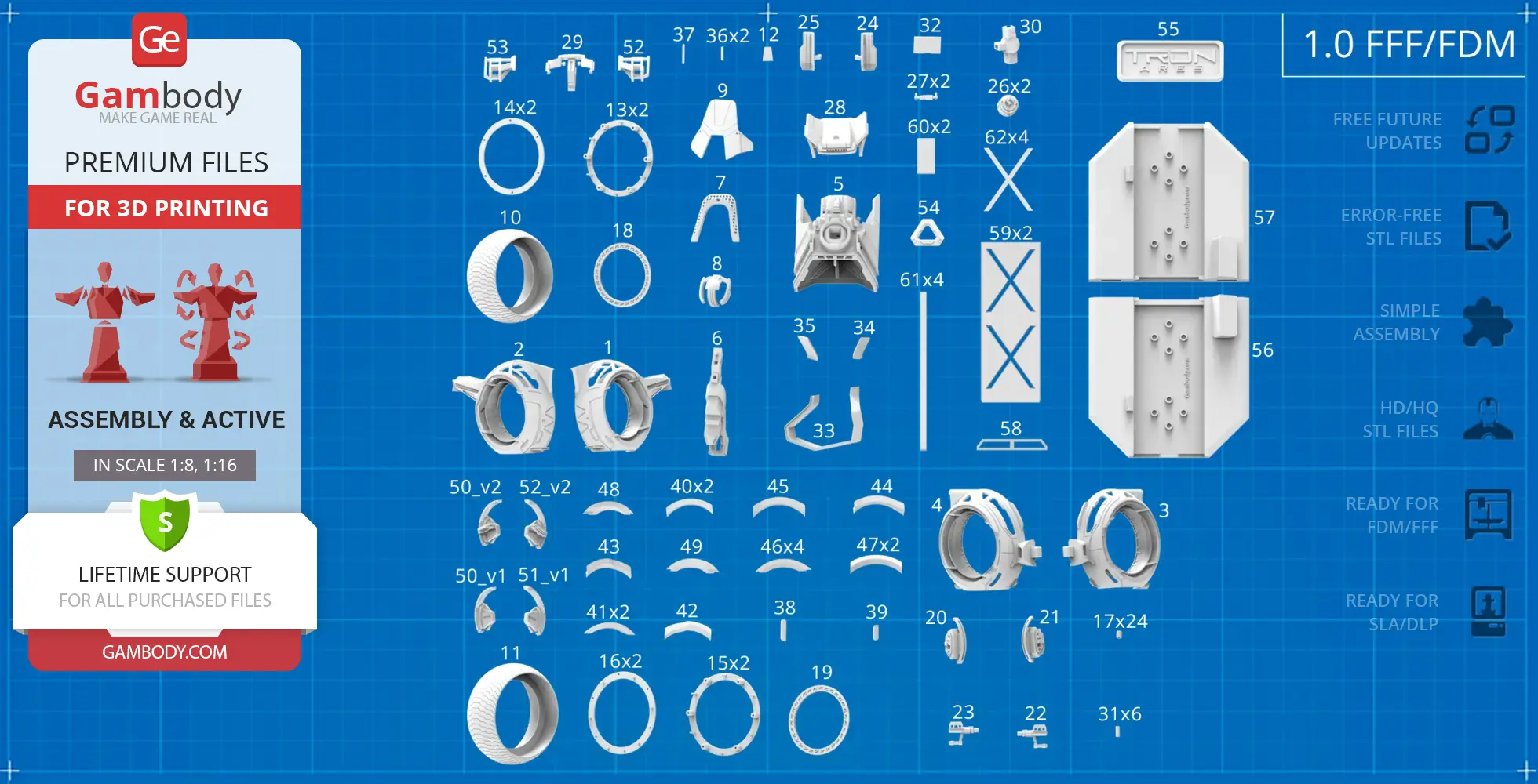
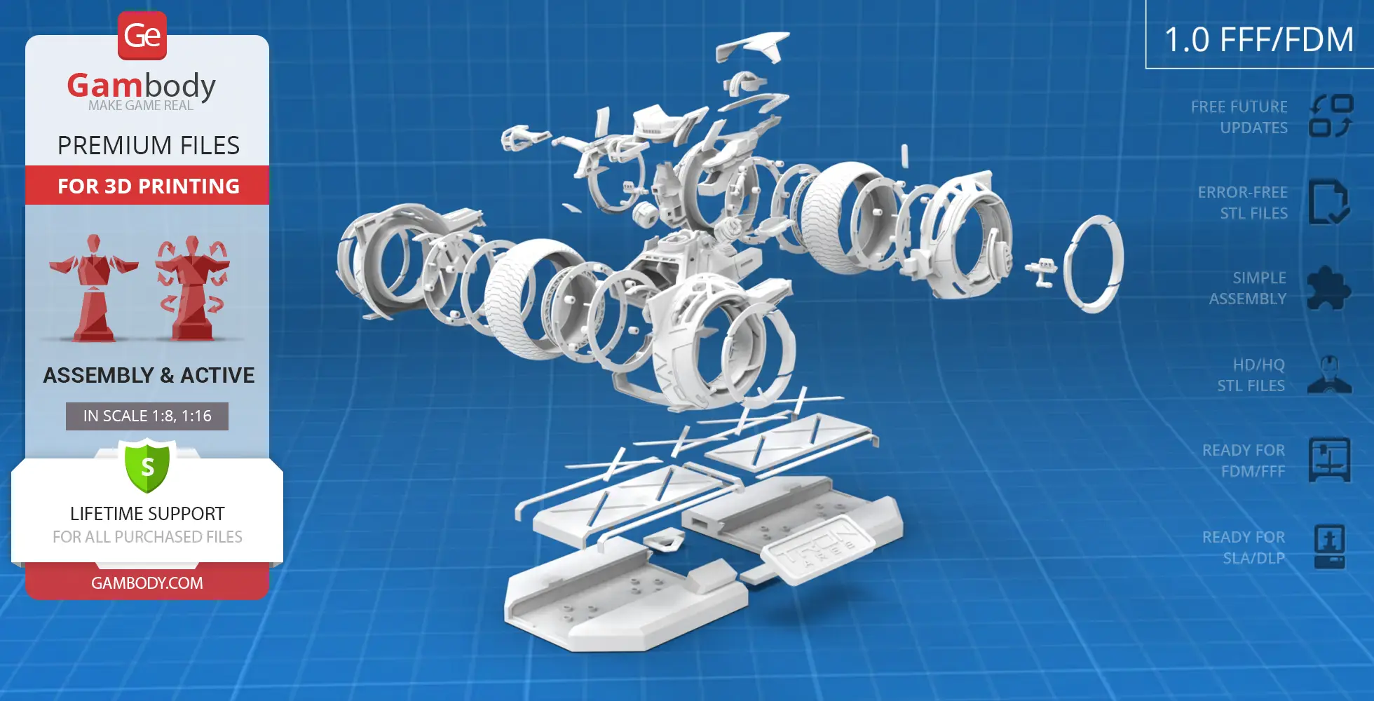
FFF/FDM
Assembly method
Connectors, Glue
Features
Updated version with design improvements and expanded features; Includes Standard and Speed Mode build variants; Enhanced LED support for headlight, turn signals, and thin light strips; Includes all core features from version 1.0: rotating wheels on bearings and dual handlebar positions; Two brake variants matched to each handlebar position; Supports optional LED installation or reflective/glow-in-the-dark inserts; Display stand supports illumination with integrated battery compartment; The assembly parts are connected using specially designed integrated connectors that fit securely into the corresponding slots; Optionally, for added strength and rigidity, the static connections can be glued together.
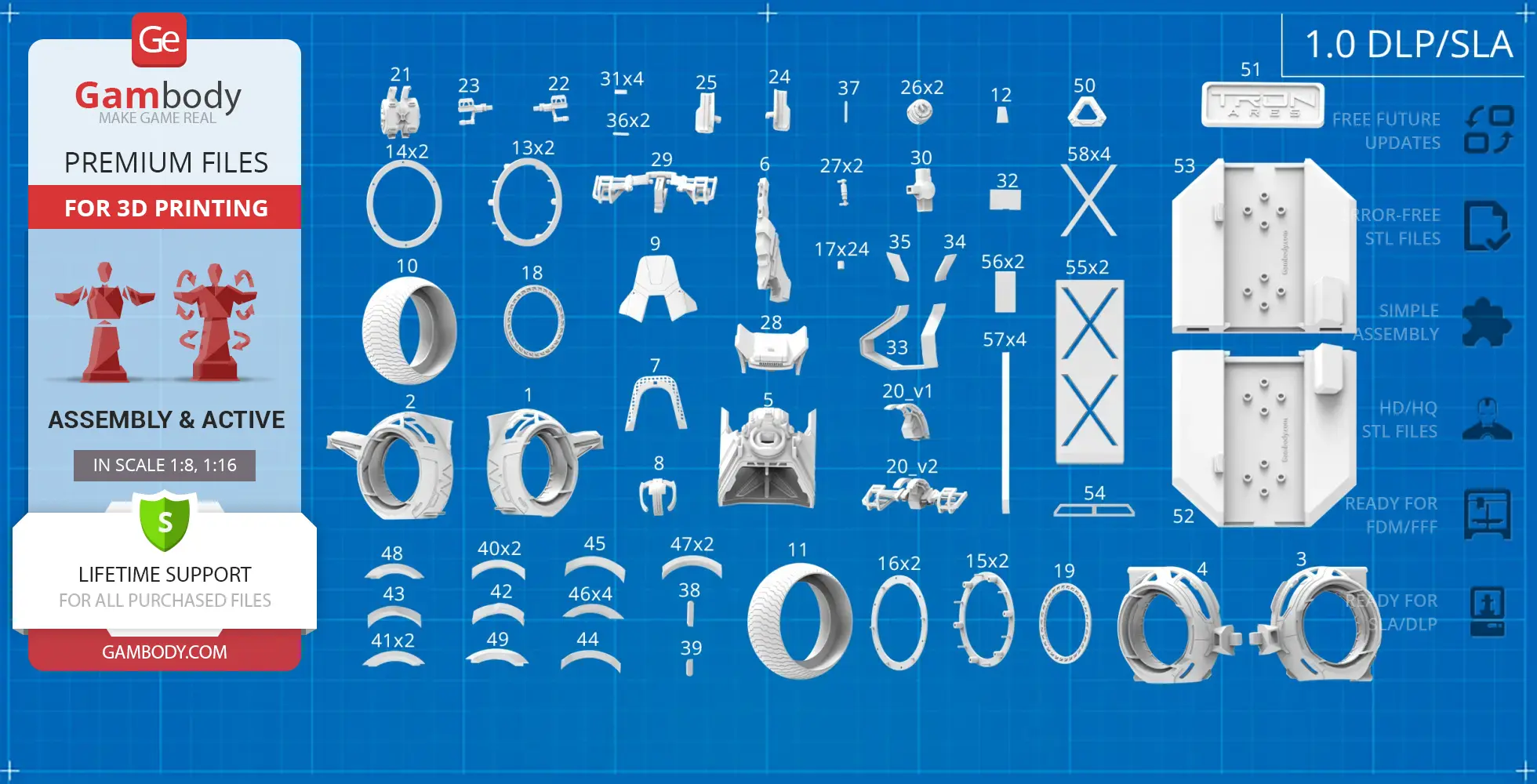
DLP/SLA
Eco parts
Assembly method
Connectors, Glue
Features
Updated version with design improvements and expanded features; Includes Standard and Speed Mode build variants; Enhanced LED support for headlight, turn signals, and thin light strips; Includes all core features from version 1.0: rotating wheels on bearings and dual handlebar positions; Two brake variants matched to each handlebar position; Supports optional LED installation or reflective/glow-in-the-dark inserts; Display stand supports illumination with integrated battery compartment; The assembly parts are connected using specially designed integrated connectors that fit securely into the corresponding slots; Optionally, for added strength and rigidity, the static connections can be glued together.
FFF/FDM
Assembly method
Connectors, Glue
Features
Rotating wheels on bearings; Upper and lower handlebar positions; Two brake variants matched to each handlebar position; Supports optional LED installation or reflective/glow-in-the-dark inserts; Display stand supports illumination with integrated battery compartment; The assembly parts are connected using specially designed integrated connectors that fit securely into the corresponding slots; Optionally, for added strength and rigidity, the static connections can be glued together.
DLP/SLA
Eco parts
Assembly method
Connectors, Glue
Features
Rotating wheels on bearings; Upper and lower handlebar positions; Two brake variants matched to each handlebar position; Supports optional LED installation or reflective/glow-in-the-dark inserts; Display stand supports illumination with integrated battery compartment; The assembly parts are connected using specially designed integrated connectors that fit securely into the corresponding slots; Optionally, for added strength and rigidity, the static connections can be glued together.
Additional details
Part of diorama
Yes
Other model in diorama
Special pack included
No
You will get instant access to the STL files of TRON Ares Light Cycle 3D Printer Files | Assembly + Action after completing your purchase. Simply add the model to your cart and check out using PayPal, credit or debit card, Apple Pay, Google Pay, Alipay, or other available payment methods.
Watch the assembly video for TRON Ares Light Cycle 3D Printer Files | Assembly + Action, and explore more tutorials, behind-the-scenes content, 3D printing timelapses, and painting guides on the official Gambody YouTube channel.
This 3D model comes with StereoLithography (.STL) files optimized for 3D printing. You'll get digital files, not a physical product
Before printing, take a look at Printing Details for recommended settings and tips to achieve better results.
TRON Ares Light Cycle 3D Printer Files | Assembly + Action includes 2 version(s) for the supported 3D printer type(s): FFF/FDM, DLP/SLA. Files are available for download after purchase.
See the Description and Specifications sections for more details about this model.
3D model history
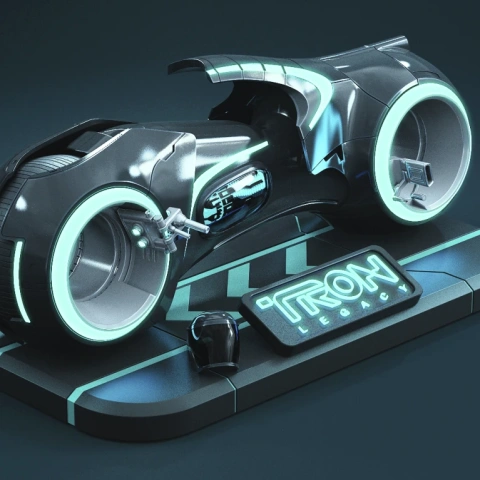
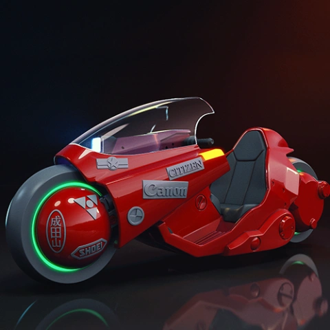
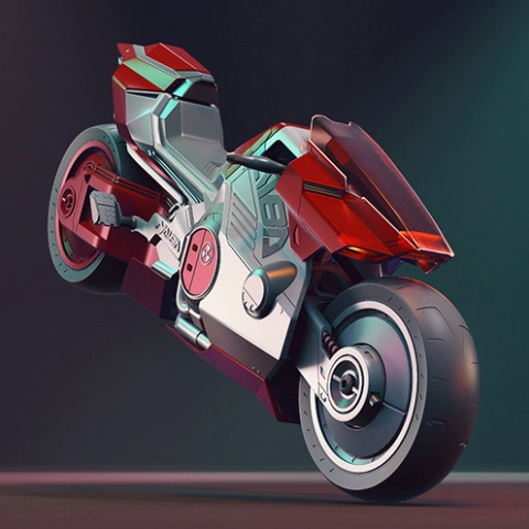
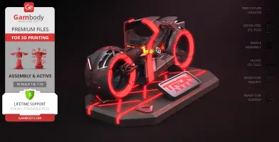
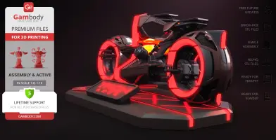
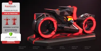
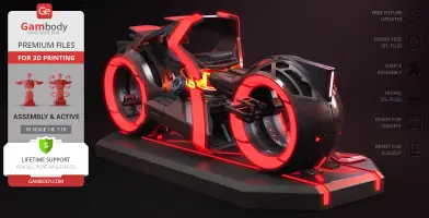
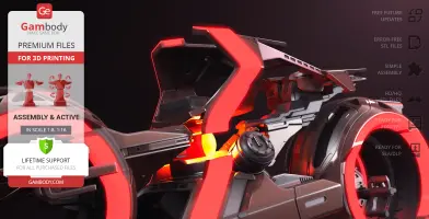
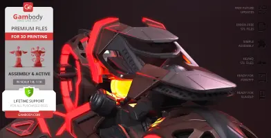
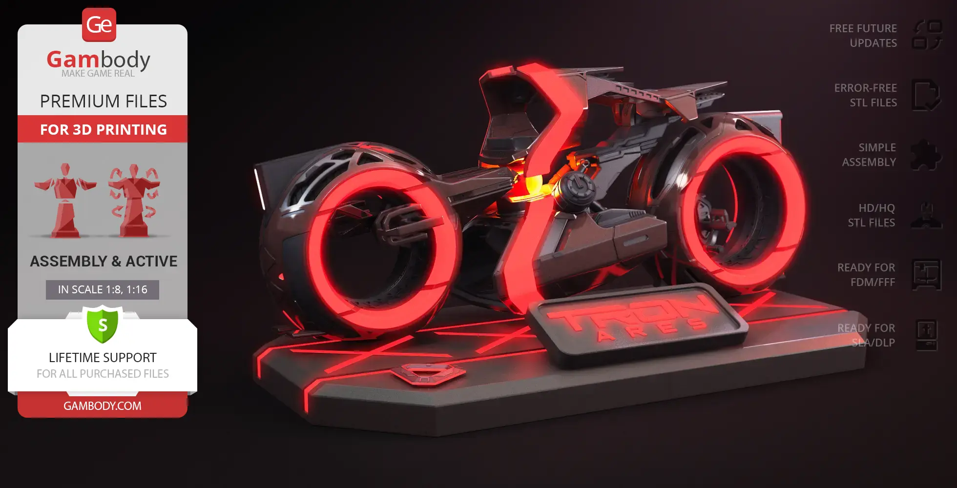
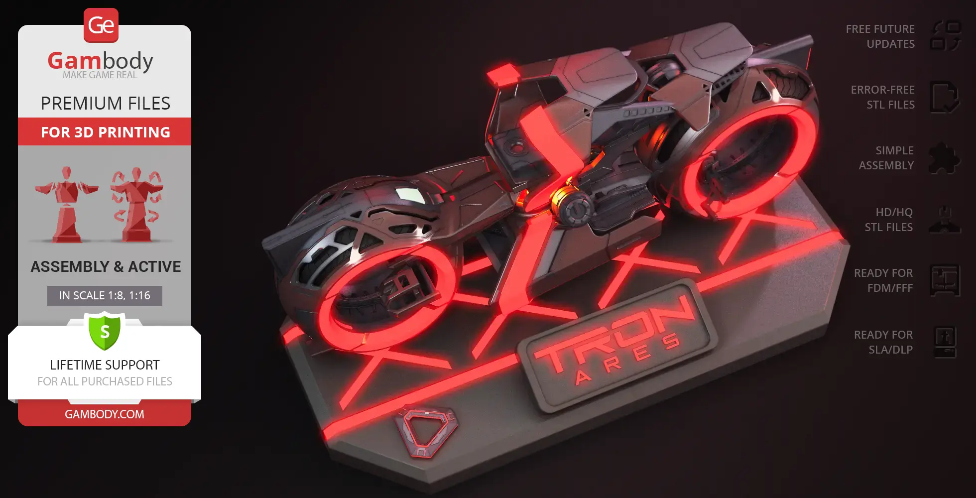
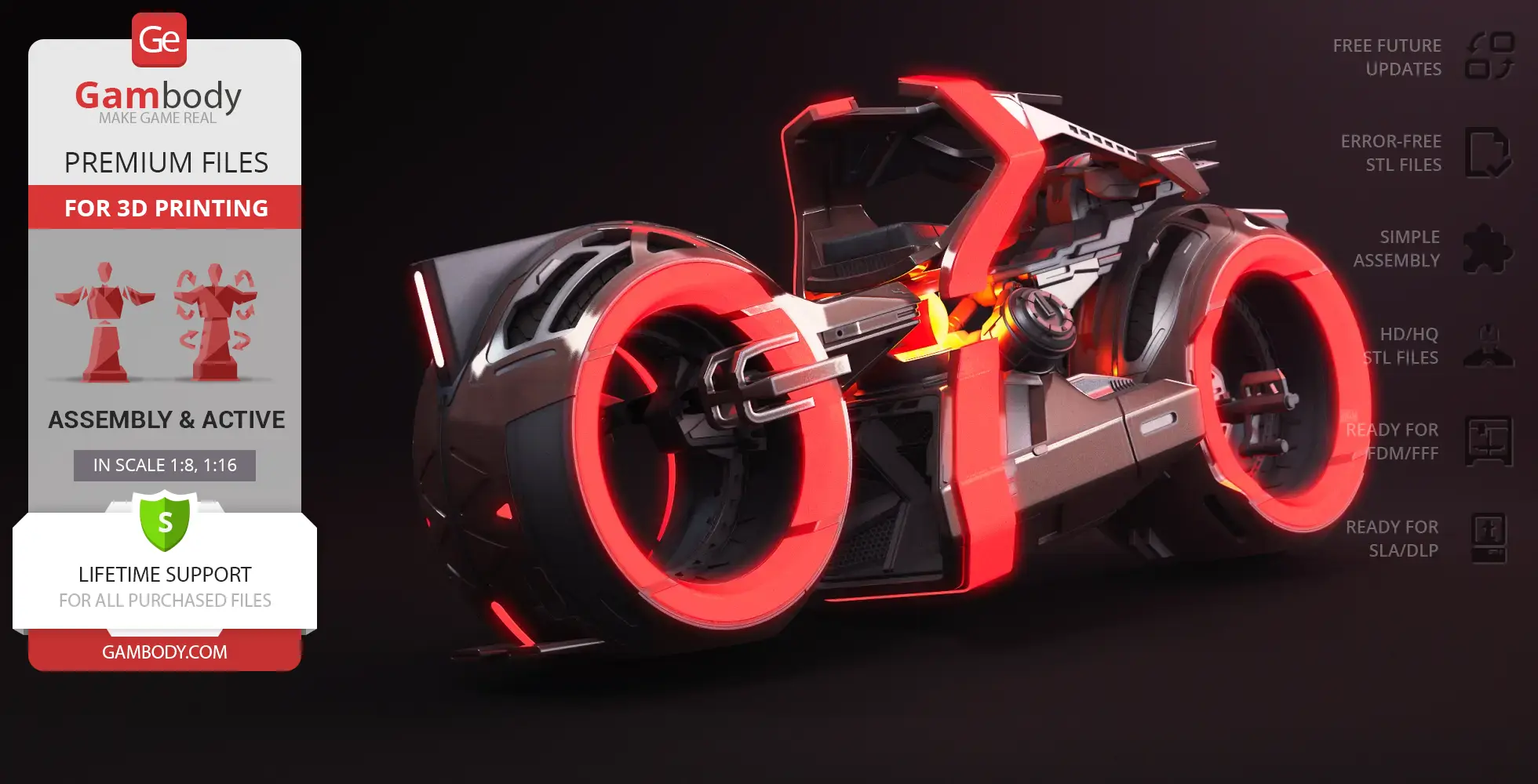
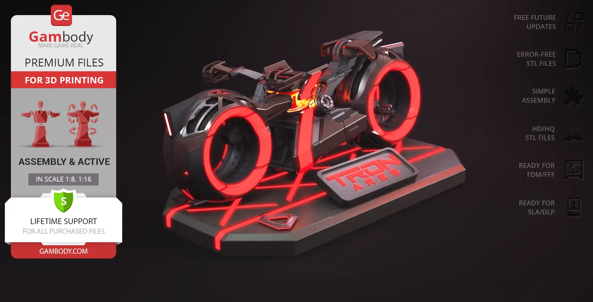
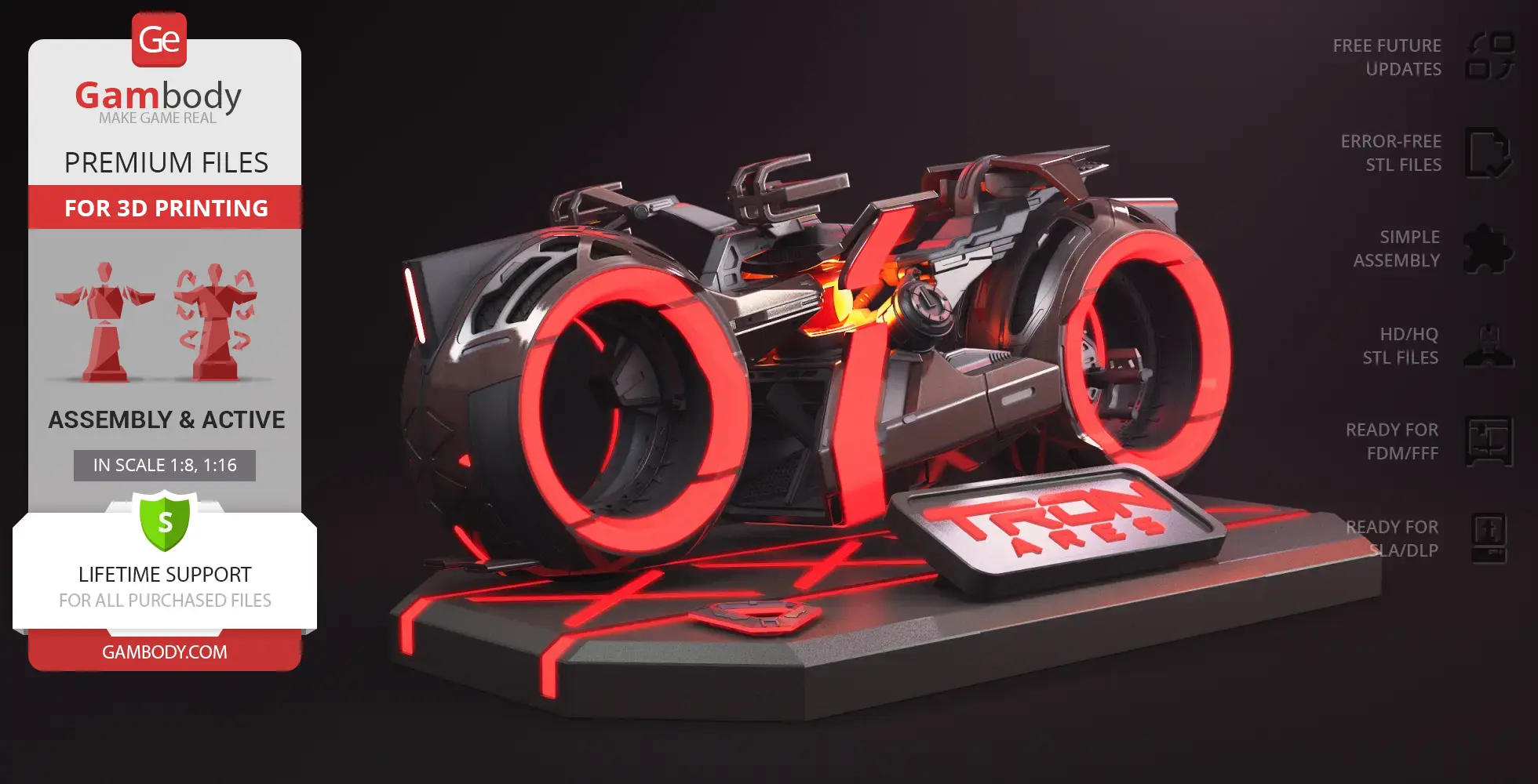
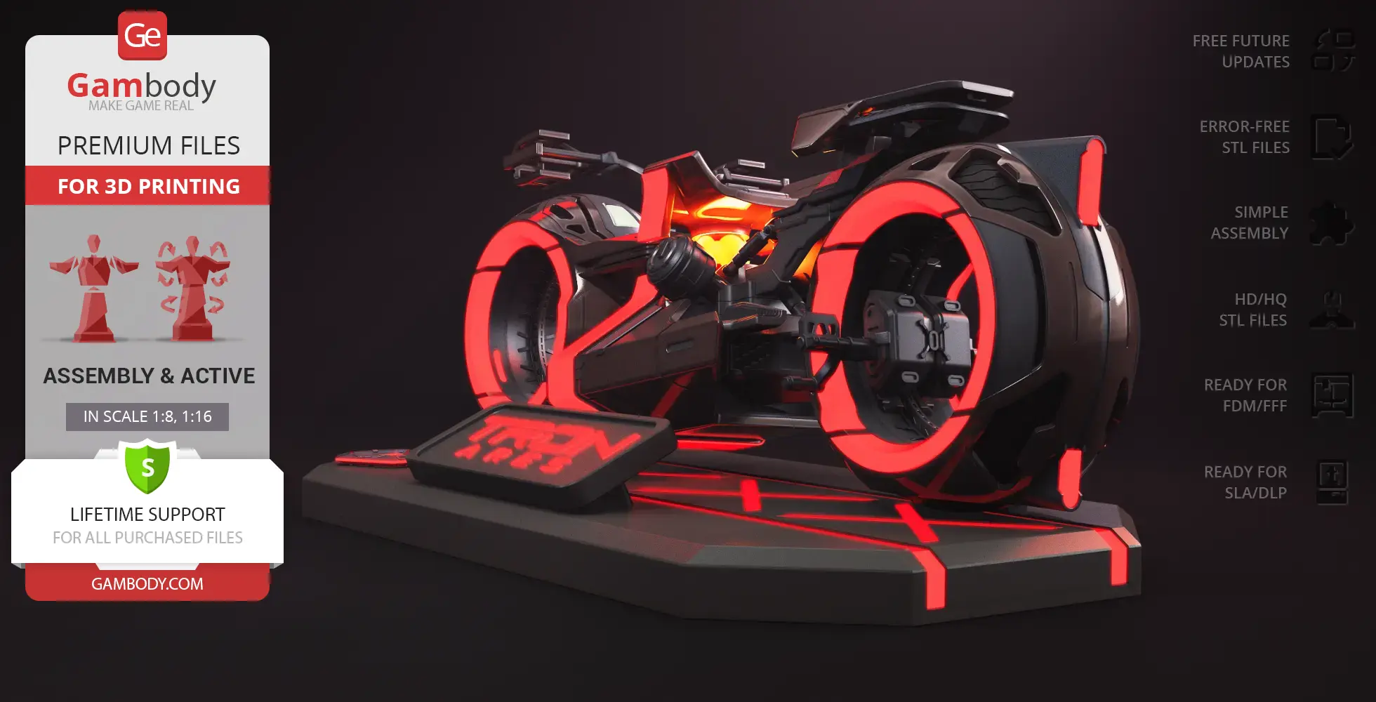
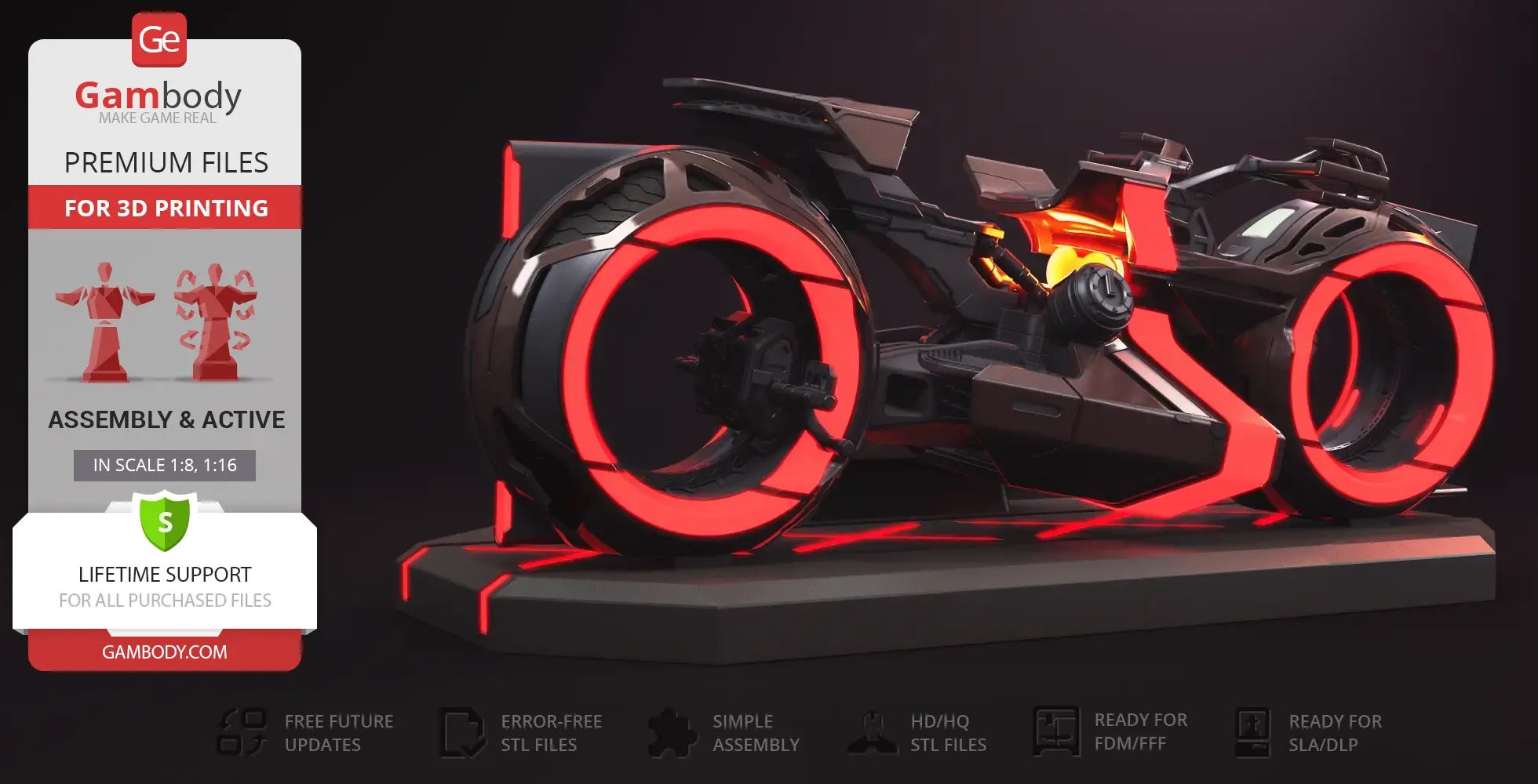
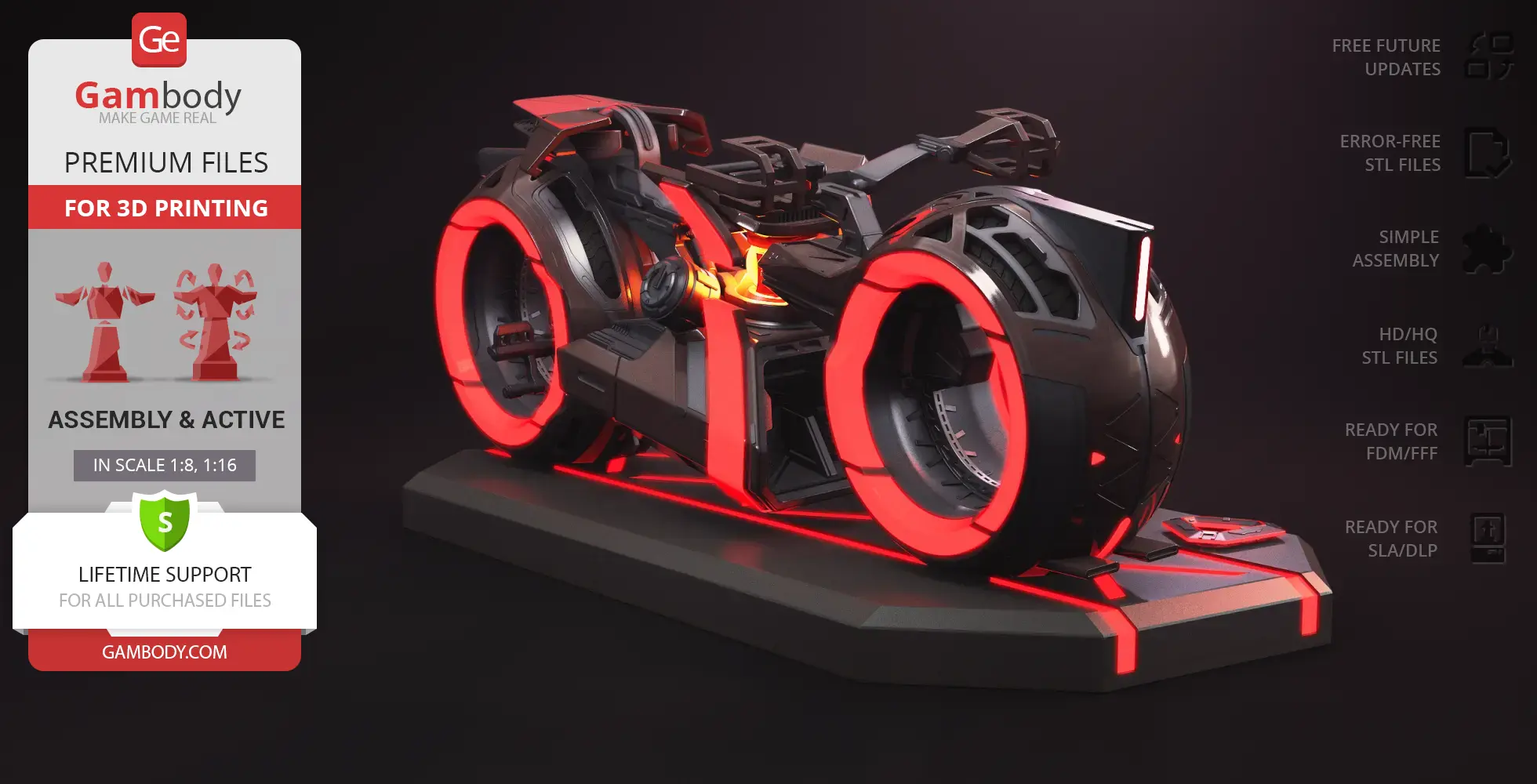
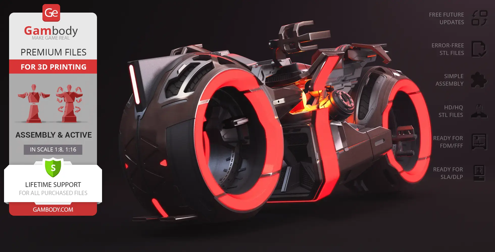
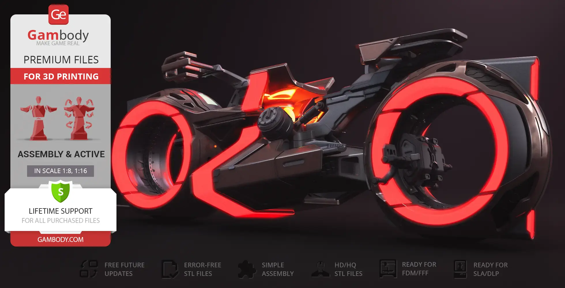
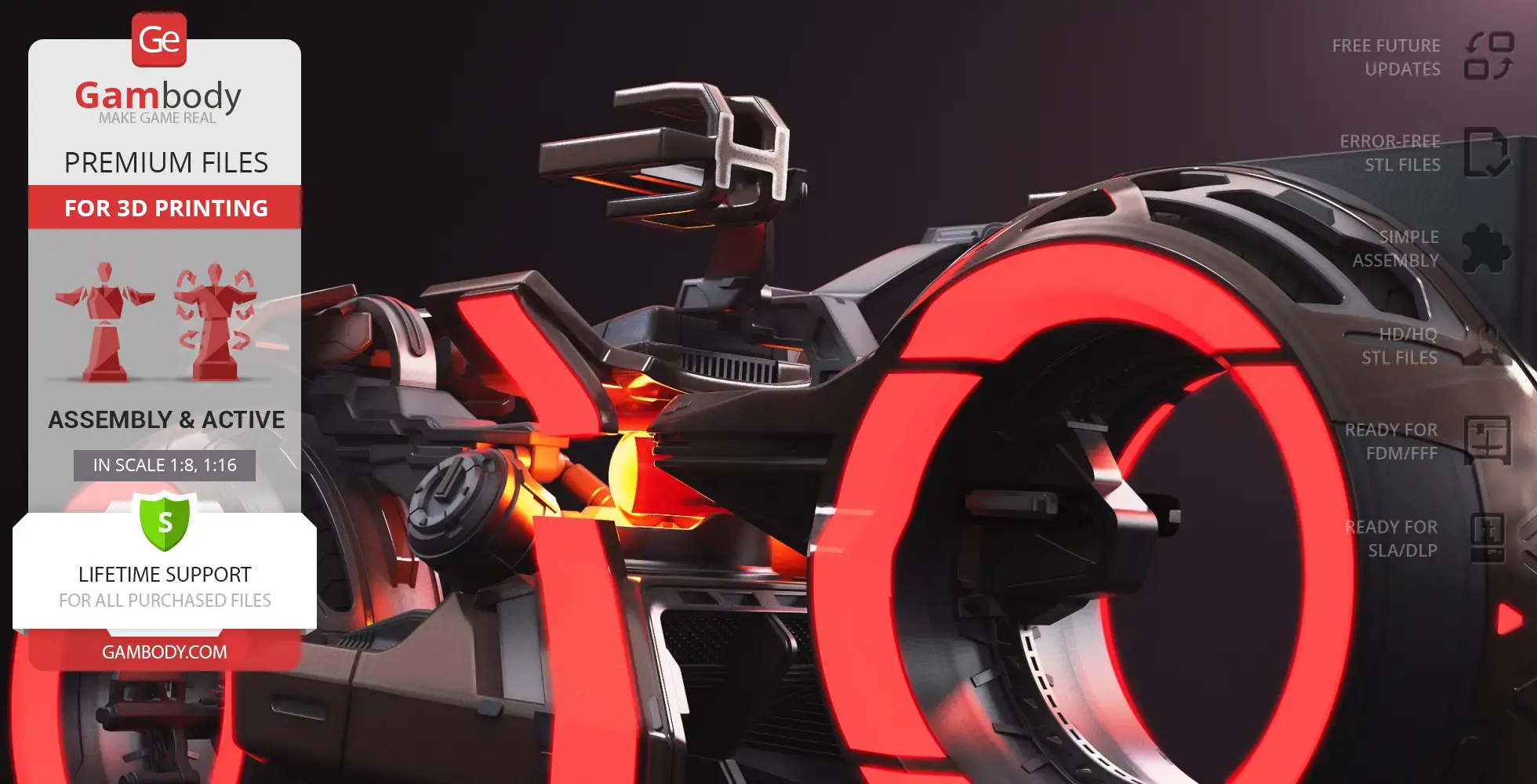
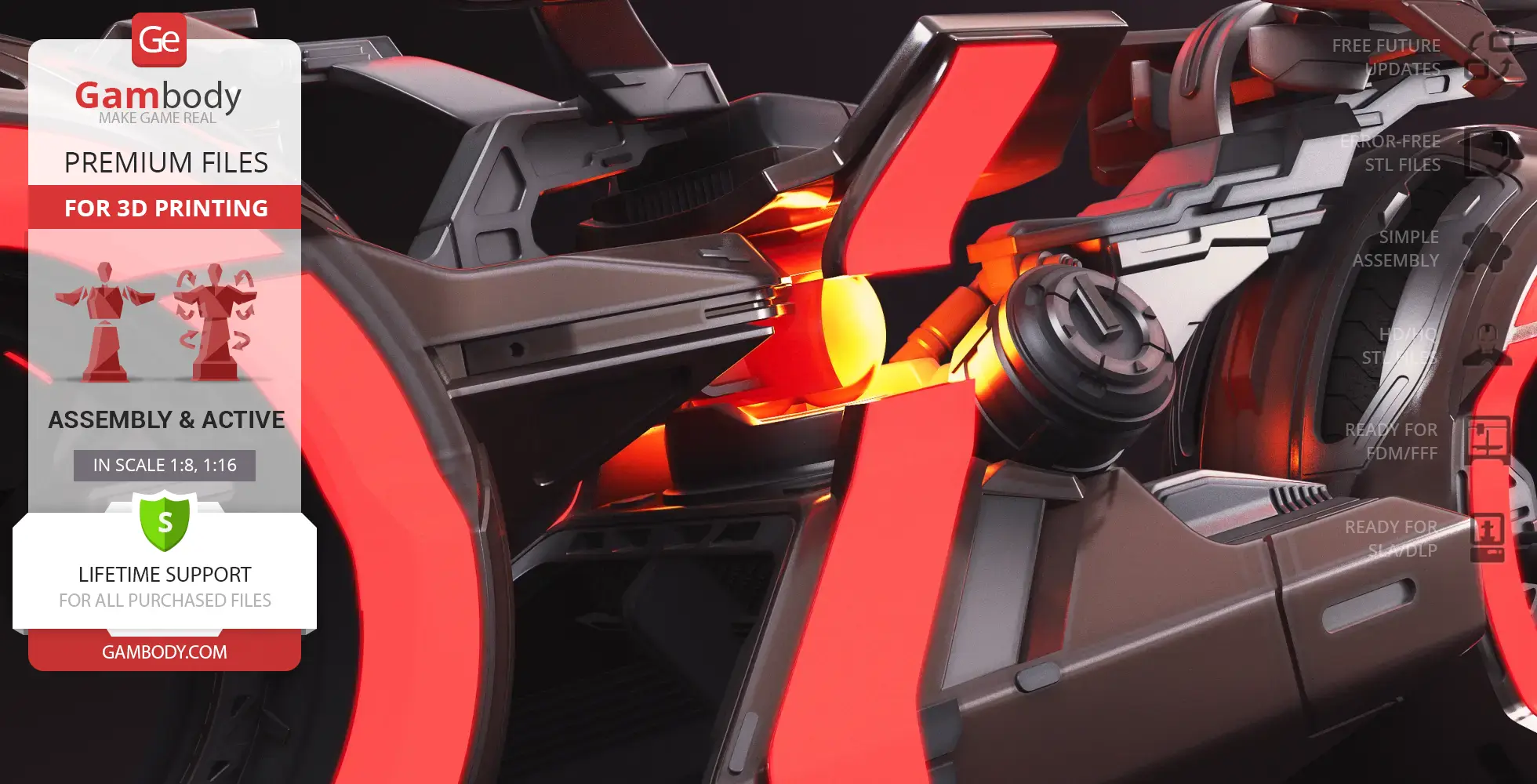
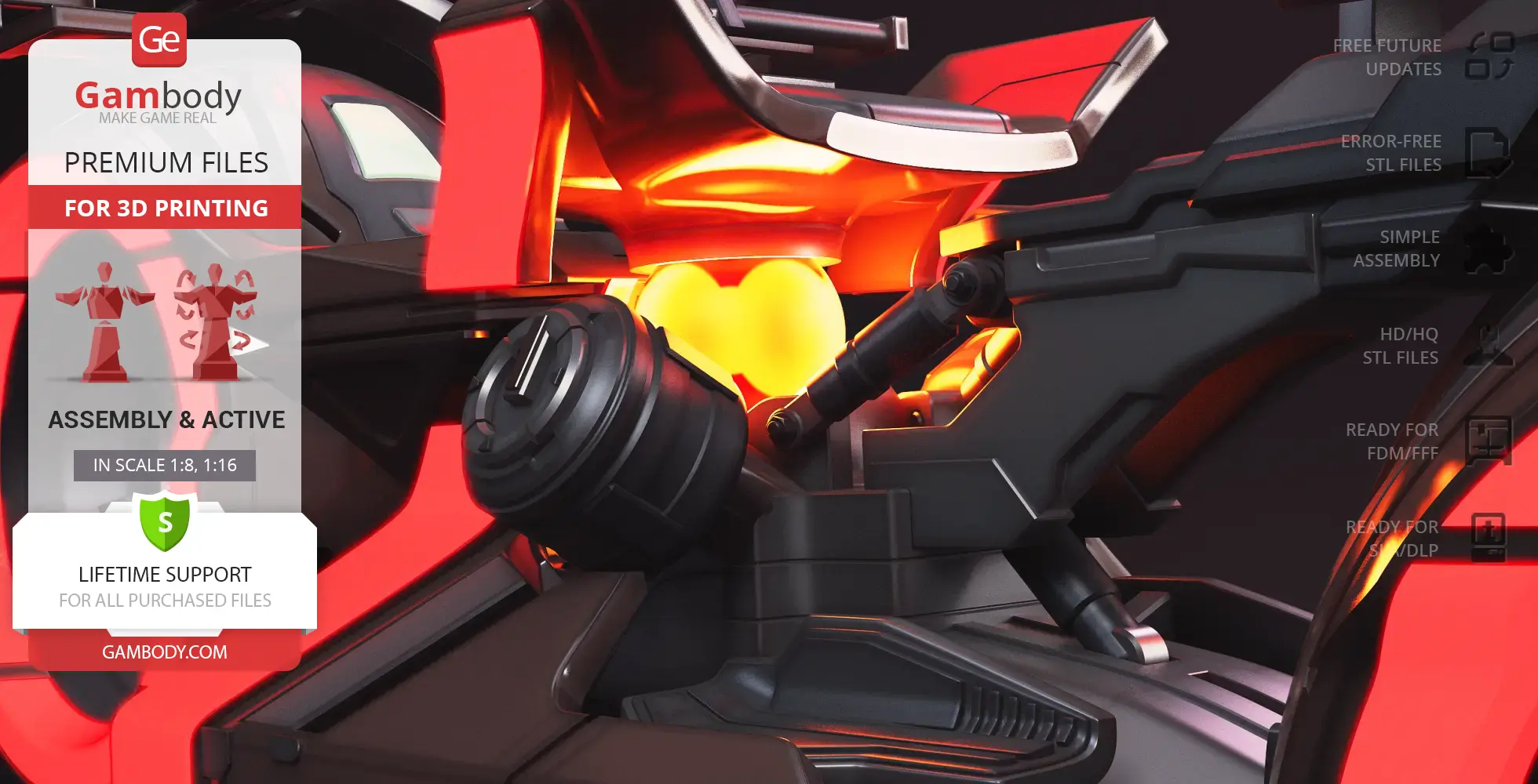
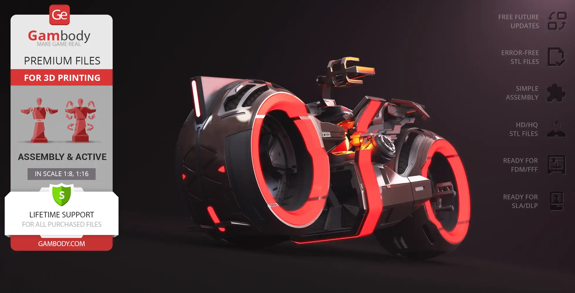
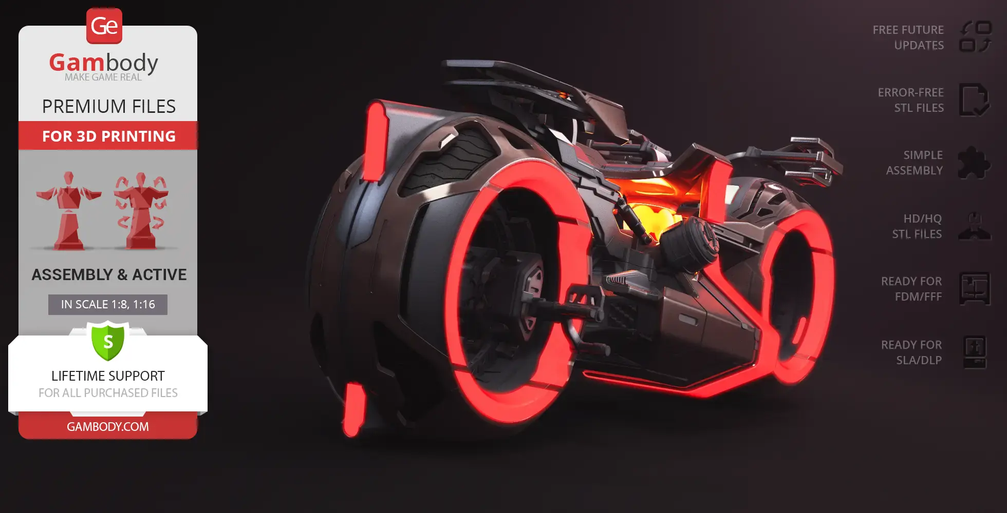
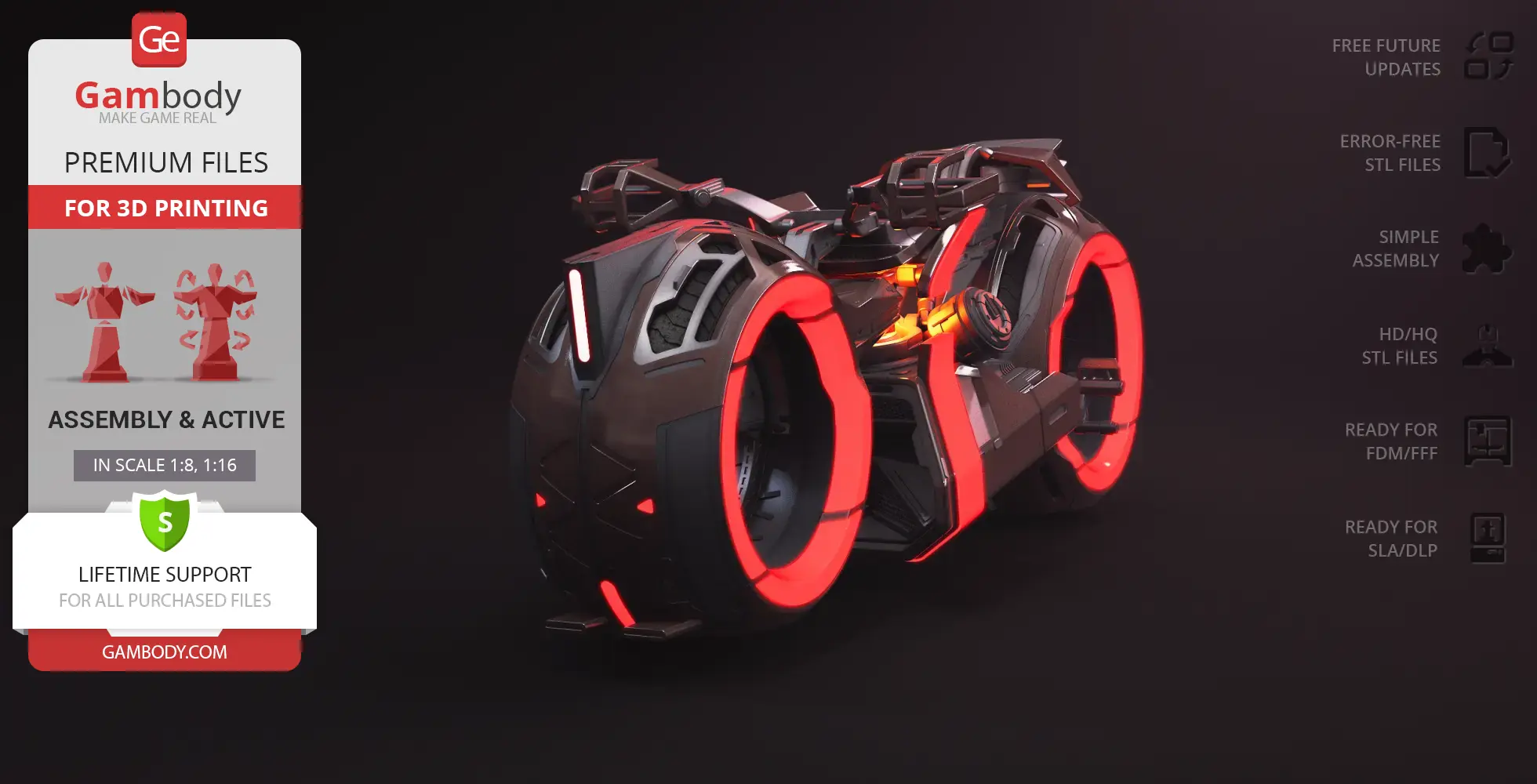
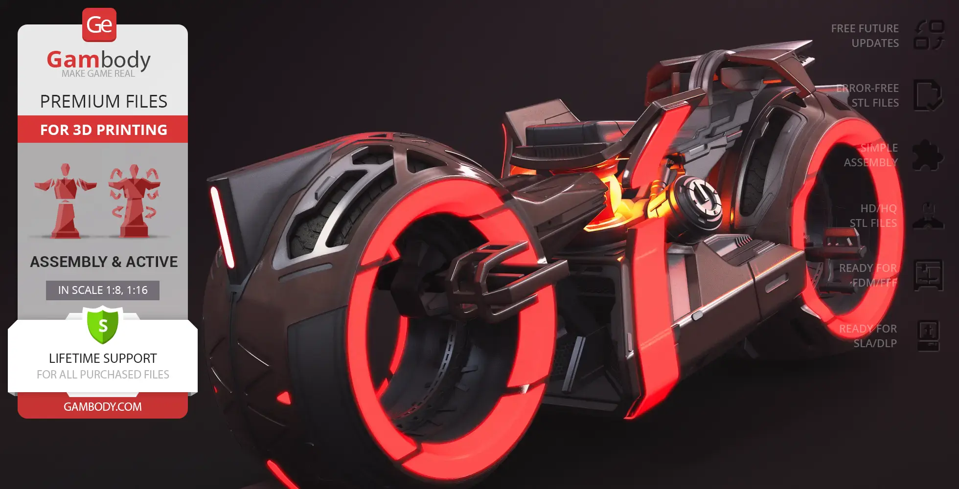
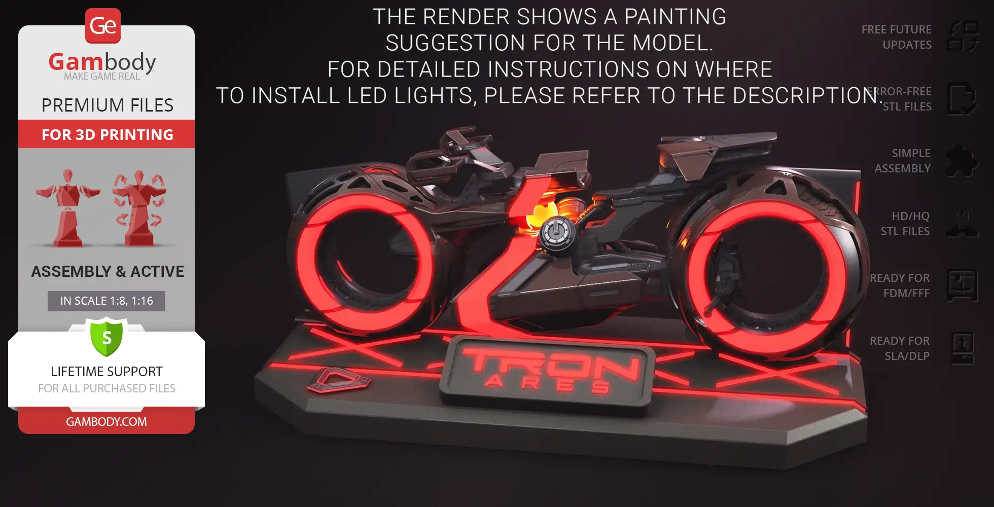
The TRON Ares Light Cycle isn't just a vehicle—it's a force of the Grid, a perfect fusion of speed, aggression, and cinematic presence. Unlike the sleek minimalism of the TRON Legacy Light Cycle, this futuristic motorcycle carries black and blood-red accents, angular armor, and a techy-military vibe that reflects the adversarial program Ares. Built as a practical prop for the movie, it bridges digital and real-world action, racing through high-speed chases while maintaining a bold, cyberpunk silhouette. A spinning yellow gyroscope at its core emphasizes its mechanical heart, making the Light Cycle feel almost alive with raw energy.
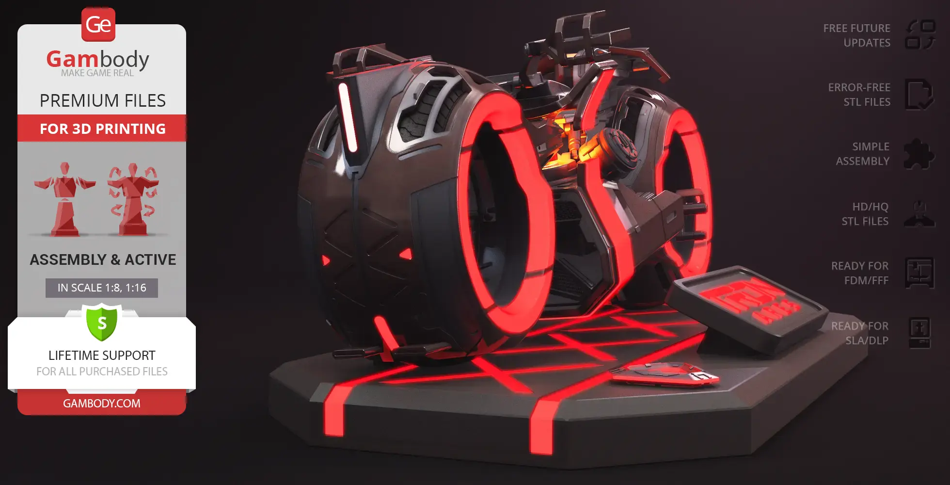
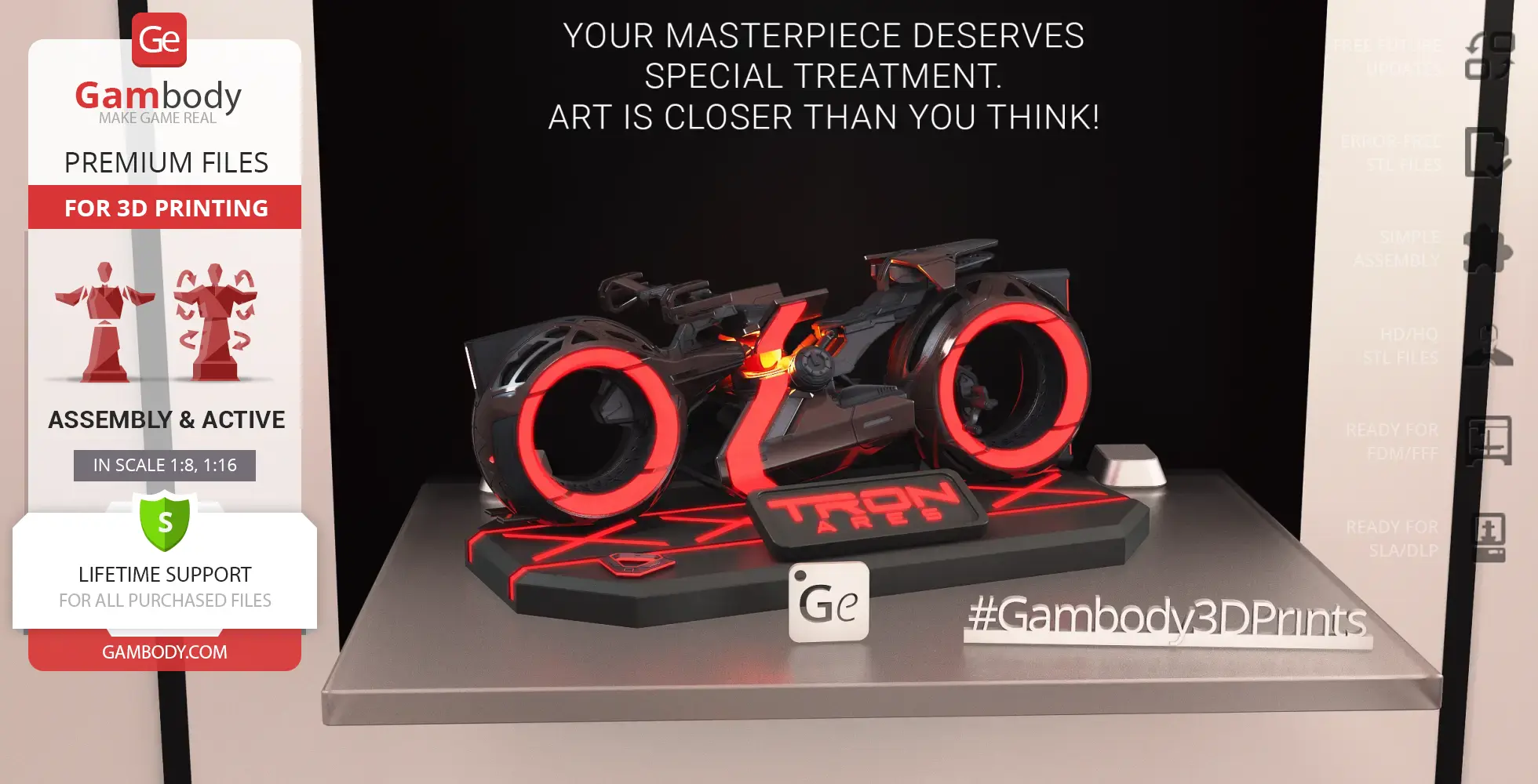
This TRON Ares Light Cycle 3D model captures that iconic on-screen intensity in a tangible collectible. Designed for 3D printing, it offers two build variants: a sleek Standard Mode and a formidable Speed Mode featuring an extendable canopy over the pilot. The model features rotating wheels, dual handlebar positions, and two brake variants matching each handlebar setup. Builders can add optional LED lighting or reflective/glow-in-the-dark elements, while the display stand cleverly houses the battery for an illuminated presentation. Whether you're hunting for a futuristic motorcycle, sci-fi 3D model, or TRON-inspired vehicle STL files, this Light Cycle 3D model is a striking centerpiece for fans of the TRON universe, movie 3D models, and high-impact bike STL builds.
3D printing model features
Model-specific features:
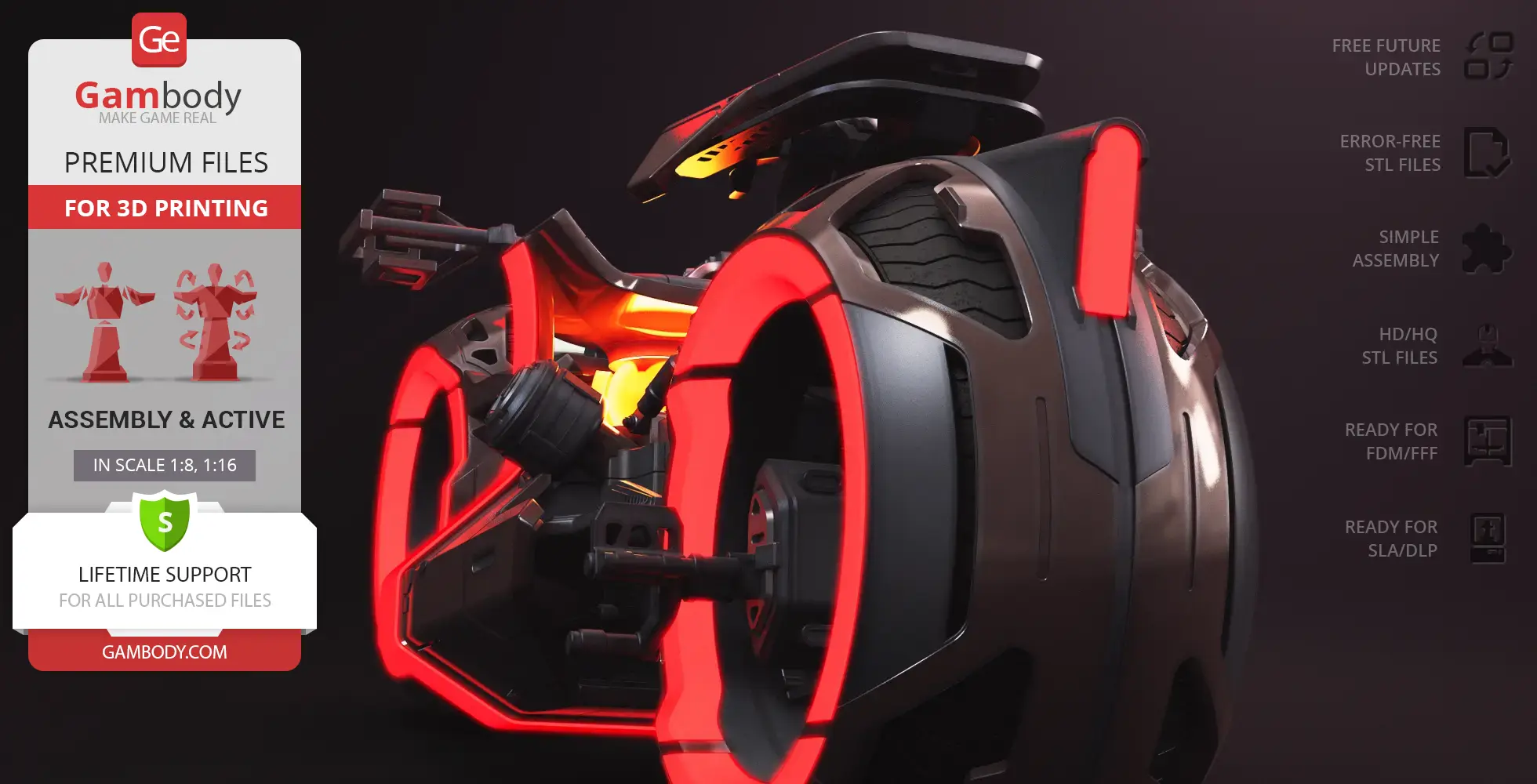
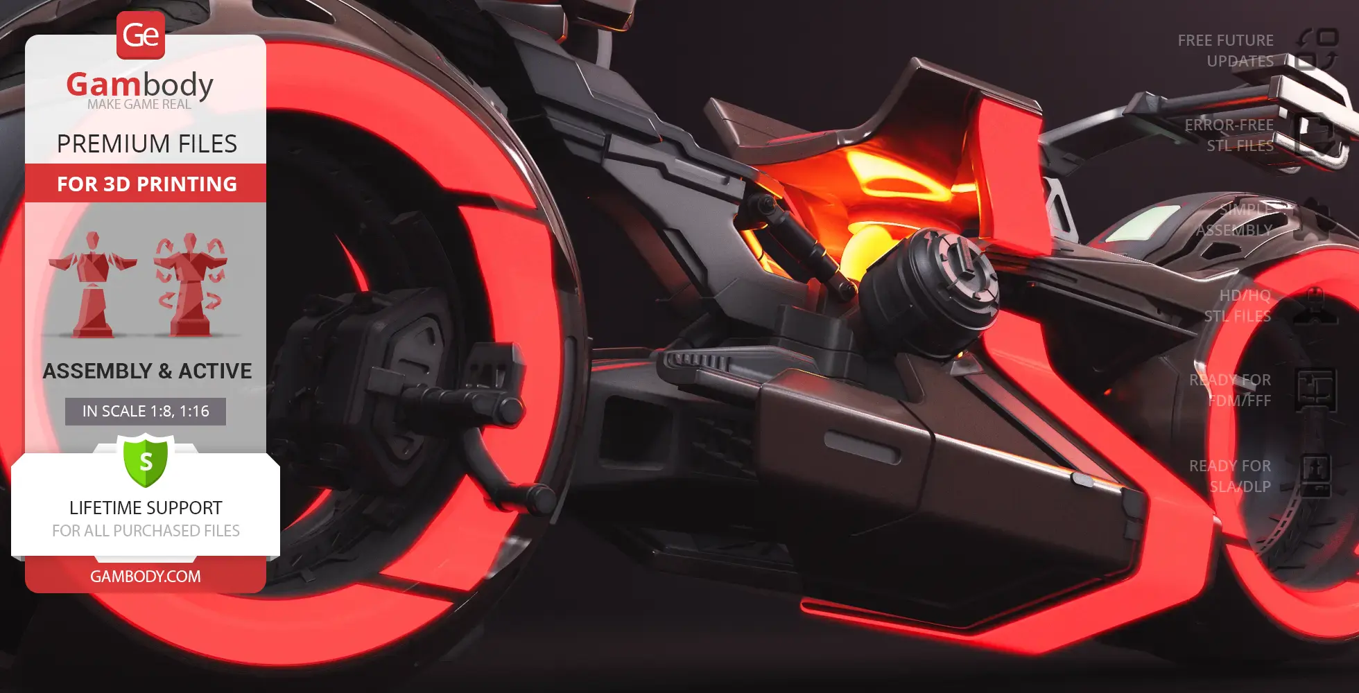
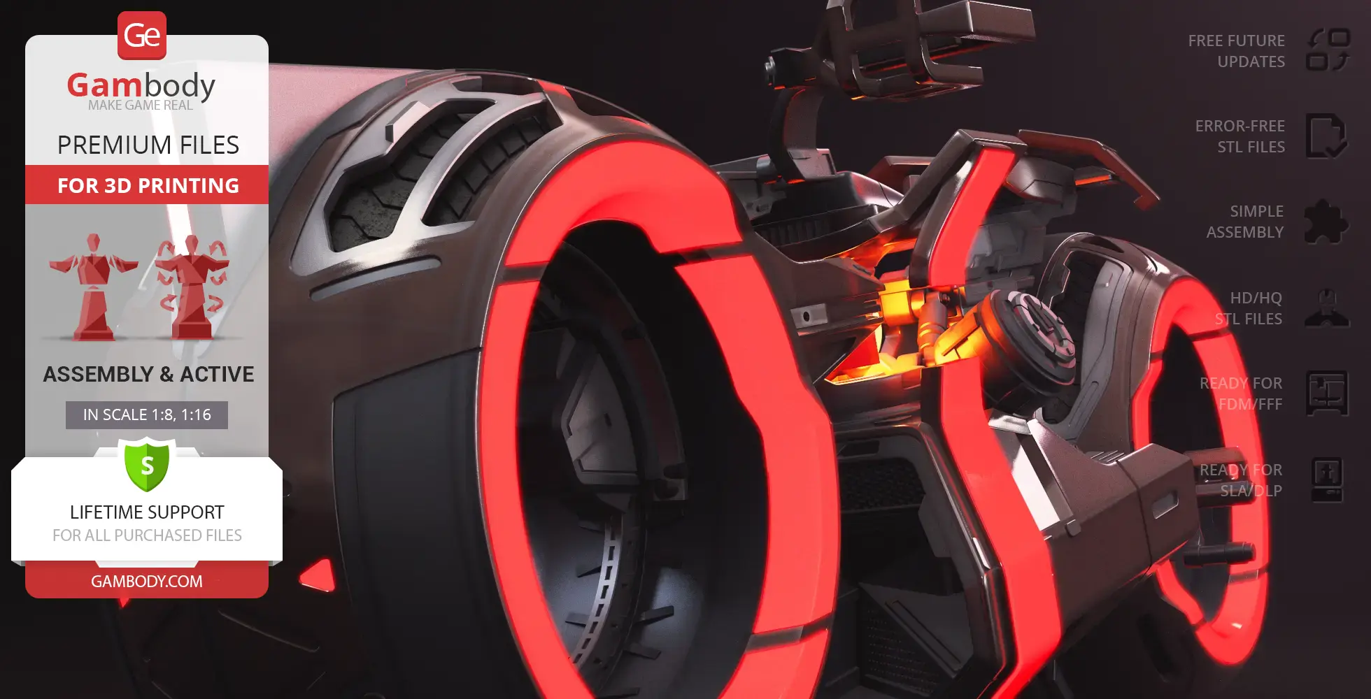
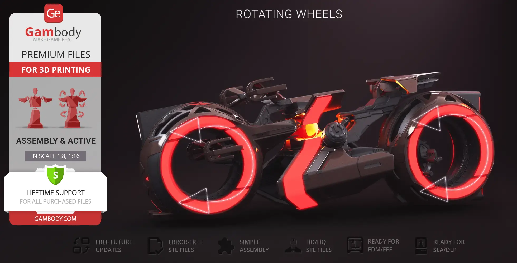
- This TRON Ares Light Cycle model is engineered for dynamic presentation, featuring wheels that rotate on bearings.
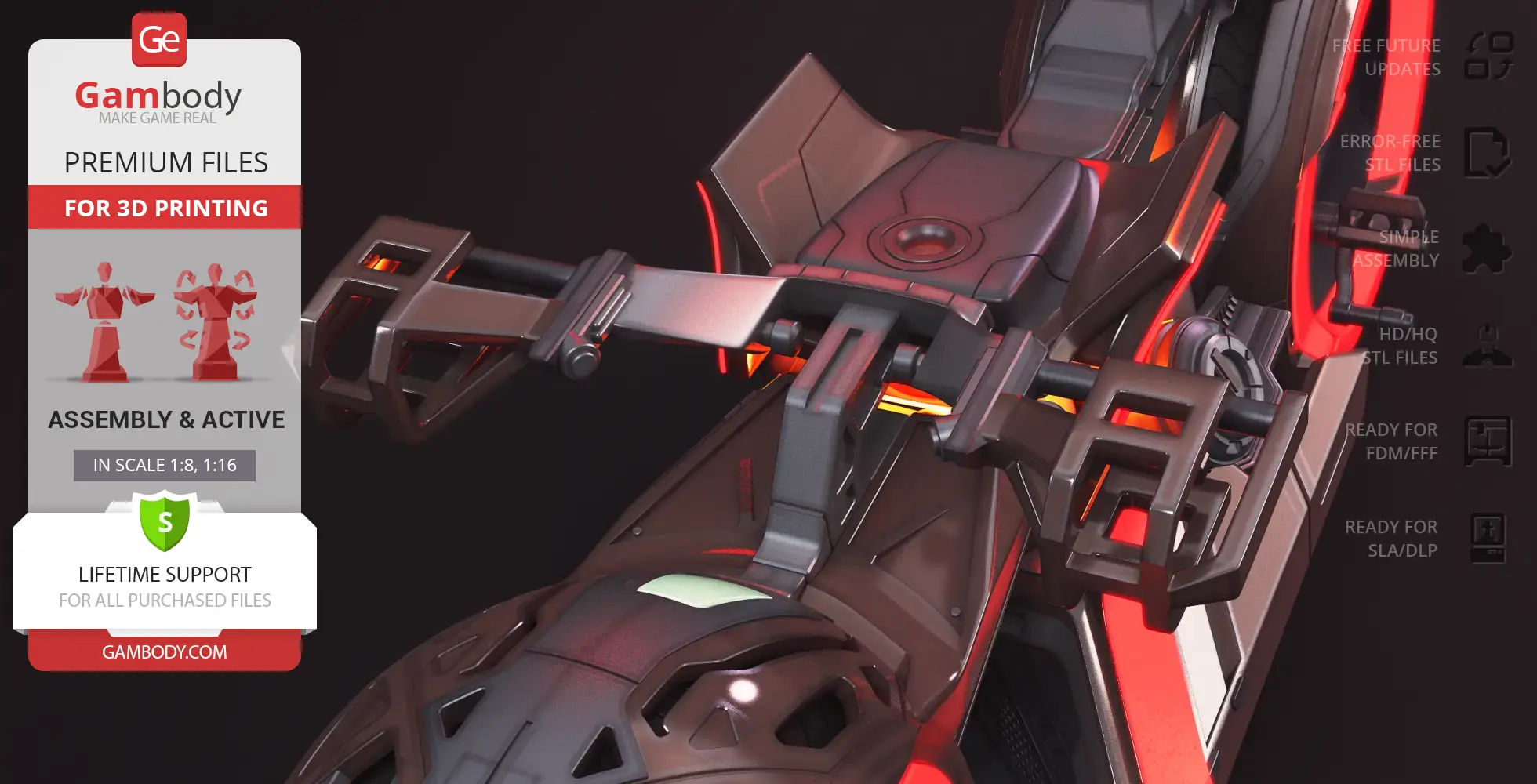
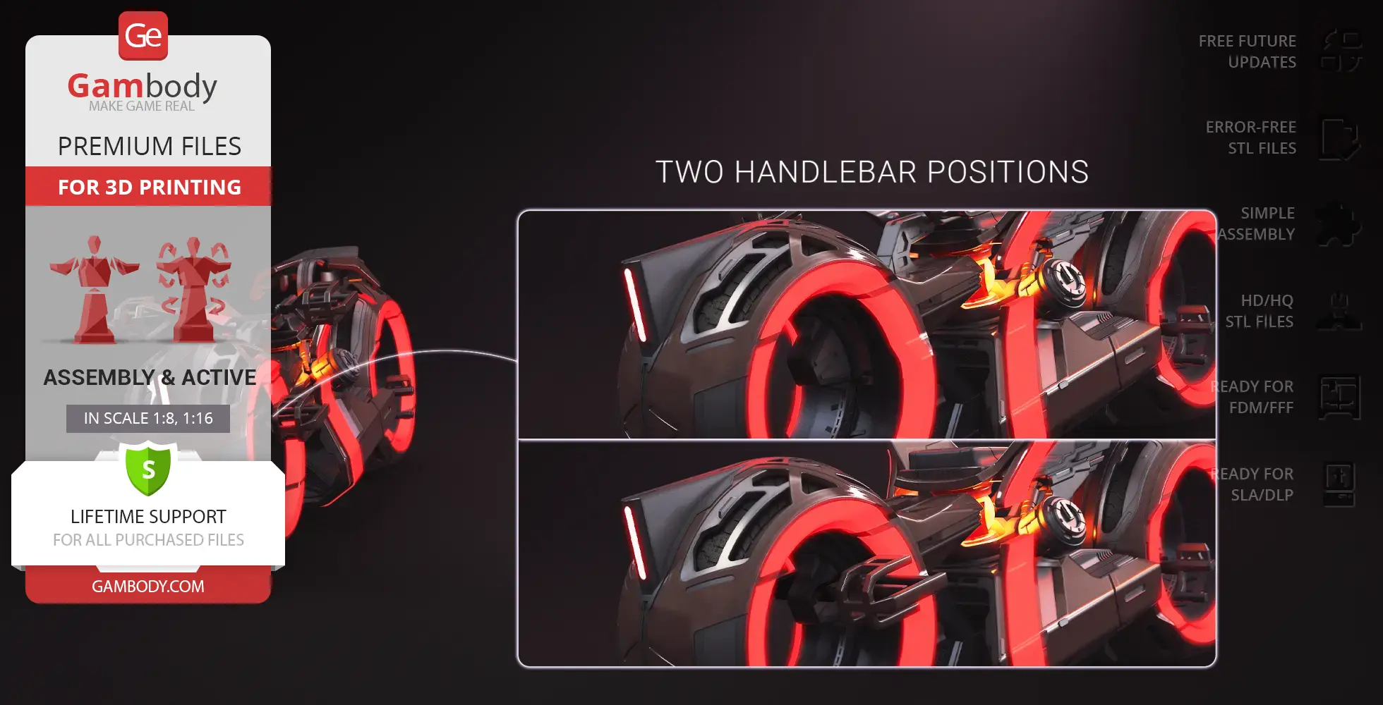
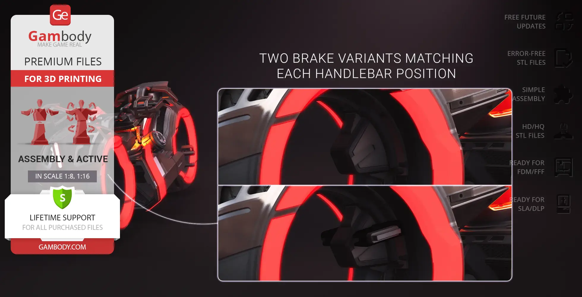
- The model allows for versatile posing with two handlebar positions: upper and lower. The files include two corresponding brake variants that match the chosen handlebar position.
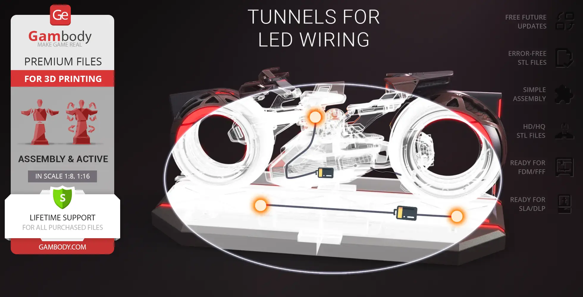
- Supports optional internal LED lighting installation for the light strips, or the use of insertable elements made from reflective or glow-in-the-dark material to achieve the iconic TRON glow.
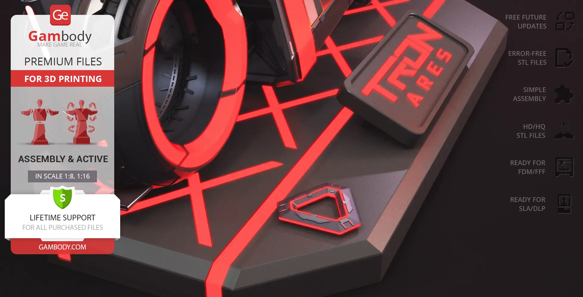
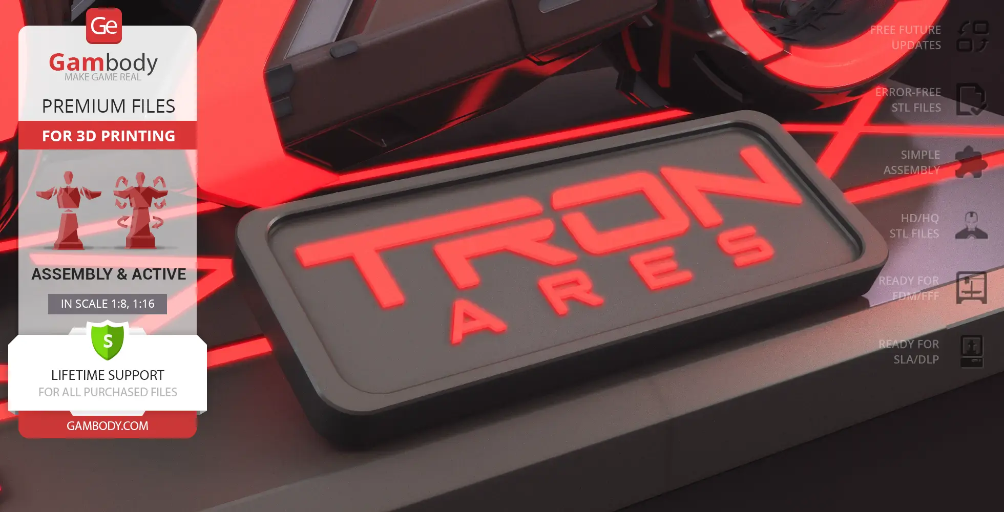
- The dedicated display stand can also be illuminated, with an integrated compartment cleverly housing the battery within the stand for a clean presentation.
- Choose between the classic Standard Mode or the Speed Mode (version 1.1), which includes the iconic extendable protective structure for the pilot.
- Version 1.1 supports optional LED installation for the headlight, turn signals, and refined light strips, with specific cover plate and body shell options for a hollow or solid finish.
Printing & assembly details:
- Provided as error-free STL files compatible with most 3D printers;
- Optimized part division minimizes support material and ensures smooth surface detail;
- The assembly parts in the FFF/FDM version come in the recommended print orientations for easy bed placement;
- Assembly manual in PDF and video formats is included for both FFF/FDM and DLP/SLA versions;
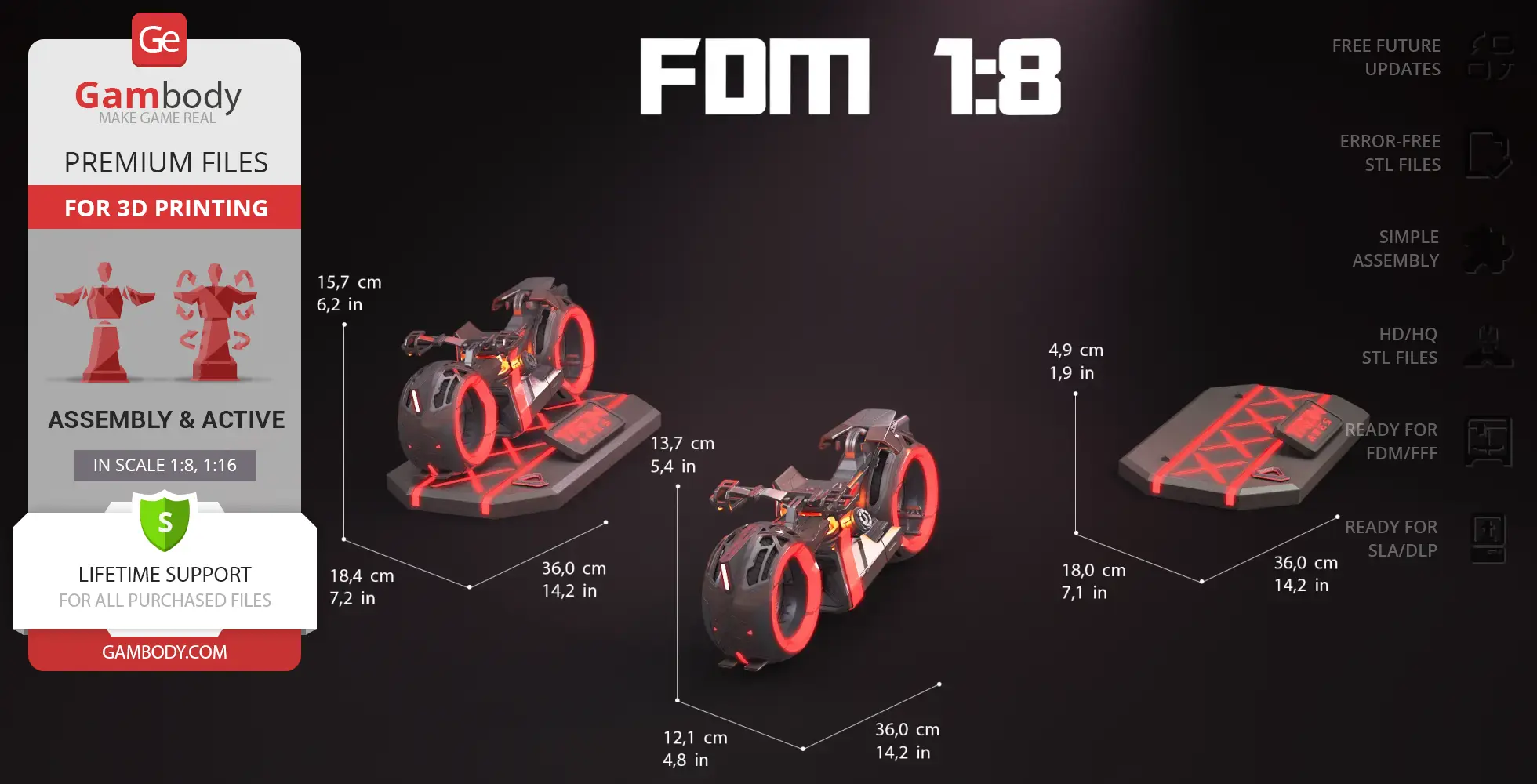
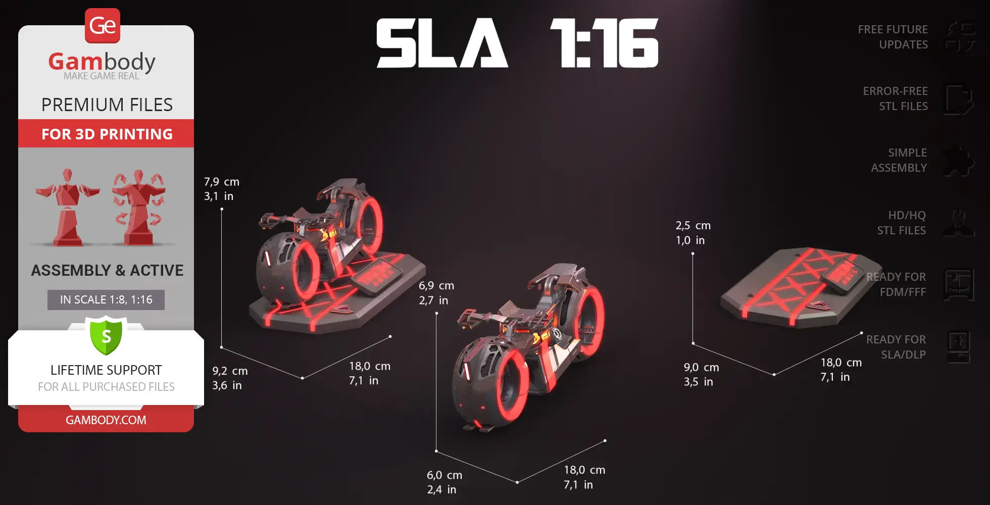
- The model is available in recommended scales of 1:8 for the FFF/FDM versions and 1:16 for the DLP/SLA versions.
What will you get after purchase?
- 4 versions of TRON Ares Light CycleSTL files for FFF/FDM and DLP/SLA — files for all versions are available for download after the purchase;
- STL files of high-poly TRON Ares Light Cycle model for 3D printing consist of 282 files;
- Sizes for:
- FFF/FDM Model Size: 121 mm wide, 137 mm high, 360 mm deep;
- FFF/FDM Model Size Speed Mode: 104 mm wide, 153 mm high, 360 mm deep;
- FFF/FDM Platform Size: 180 mm wide, 49 mm high, 360 mm deep;
- DLP/SLA Model Size: 60 mm wide, 69 mm high, 180 mm deep;
- DLP/SLA Model Size Speed Mode: 52 mm wide, 77 mm high, 180 mm deep;
- DLP/SLA Platform Size: 90 mm wide, 25 mm high, 180 mm deep;
- Assembly Manual for 1.0 FFF/FDM, 1.1 FFF/FDM, 1.0 DLP/SLA, and 1.1 DLP/SLA versions in PDF and video formats;
- Detailed settings that we provide as a recommendation for Bambu Studio, Cura, Orca Slicer, PrusaSlicer, Simplify3D, and Slic3r for the best print;
- Full technical support from the Gambody Support Team.
Average customer rating (3 reviews)
5
Ratings breakdown
Click a star rating to filter reviews
Overall experience
Level of detail in the model
4.9
Model cut quality and assembly guide
4.9
Clarity and accuracy of the model page
5
Level of detail in the model
4.8
Model cut quality and assembly guide
4.7
Clarity and accuracy of the model page
5
Level of detail in the model
5
Model cut quality and assembly guide
5
Clarity and accuracy of the model page
5
Level of detail in the model
5
Model cut quality and assembly guide
5
Clarity and accuracy of the model page
5
Below you'll find detailed slicing settings for Bambu Studio 2.0+, Orca Slicer 2.0+, UltiMaker Cura 5.0+, PrusaSlicer 2.0+, Slic3r 1.3+, Simplify3D 5.0+ to help you get the best results when printing this model. These settings are optimized specifically for this 3D model, but please note they may need slight adjustments depending on your printer or filament. When in doubt, refer to your printer's user manual.
To avoid printing issues and achieve the best quality, we highly recommend applying the following settings:
For better quality use 0.12 mm layer height, for fast printing use 0.2 mm layer height. For pins and the Ge connectors, use 0.2 layer height.
120-150% of your Layer Height
But you can paint the seam if you want.
You have to calibrate this parameter
You have to calibrate this parameter
You have to calibrate this parameter
For pins and power elements of the structure, such as the vehicle frame, use 3 loop
Disabled for vehicles and enabled for characters
For 0,2 Layer Height
The parameters in this tab vary greatly, it all depends on the quality of your printer. For example, if you have a classic Ender3, stick to the minimum parameters, but if you have a newer printer, for example Anycubic cobra 3 v2, you can select the maximum recommended values
Settings for advanced users, change these parameters only if you have sufficient 3D printing expertise
Enable this parameter if your model requires supports
We also recommend placing and removing supports manually in some places using special button
1-2 loops for more thick support
Top Z distance = 1-1.3 layer Height. If the supports are hard to remove, try increasing this setting by 0.1-0,4 mm
Bottom Z distance = 1-1.3 layer Height. If the supports are hard to remove, try increasing this setting by 0.1-0,4 mm
You have to calibrate this parameter which one is better for your filament
Increase this parameter if the supports are hard to remove from walls
For PLA and PETG filament types
5-8 mm is optional for small prints that have bad adhesion to the build plate
You have to calibrate this parameter
Read the description on your filament roll
Read the description on your filament roll and increase this parameter for fast printers
Read the description on your filament roll and increase this parameter for fast printers
For better quality use 0.12 mm layer height, for fast printing use 0.2 mm layer height. For pins and the Ge connectors, use 0.2 layer height.
120-150% of your Layer Height
But you can paint the seam if you want.
0.01-0.05 You have to calibrate this parameter
0.01-0.05 You have to calibrate this parameter
0.1-0.2 You have to calibrate this parameter
For pins and power elements of the structure, such as the vehicle frame, use 3 loop
Disabled for vehicles and ships, enabled for characters
For 0,2 Layer Height
For 0,2 Layer Height
The parameters in this tab vary greatly, it all depends on the quality of your printer. For example, if you have a classic Ender3, stick to the minimum parameters, but if you have a newer printer, for example, Anycubic Kobra 3 Or Bambulab A1, you can select the maximum recommended values.
Settings for advanced users, change these parameters only if you have sufficient 3D printing expertise
Enable this parameter if your model requires supports
We also recommend placing and removing supports manually in some places using special button
Top Z distance = 1-1.3 layer Height. If the supports are hard to remove, try increasing this setting by 0.1-0,4 mm
Bottom Z distance = 1-1.3 layer Height. If the supports are hard to remove, try increasing this setting by 0.1-0,4 mm
Increase this parameter if the supports are hard to remove from walls
For PLA and PETG filament types
5-8 mm is optional for small prints that have bad adhesion to the build plate
Read the description on your filament roll
Read the description on your filament roll and increase this parameter for fast printers
You have to calibrate this parameter
Read the description on your filament roll and increase this parameter for fast printers
Read the description on your filament roll
This field is filled in according to your printer specifications when you add it to the slicer.
You can add custom G-code here for the start and end of the print. However, be careful - this is for advanced users only!
You have to calibrate your printer using Ge retraction test models
Retraction Length: For direct-drive setups use 0.5 mm to 2.5 mm; for Bowden extruders use 5 to 7 mm
This is how fast the filament is pulled back—40-60 mm/s for direct drive and 30-50 mm/s for Bowden setups.
You have to calibrate this parameter: Reduce it until the printer starts to hit the parts with the nozzle during printing, then increase it by 0.2.
For better quality use 0.12 mm layer height, for fast printing use 0.2 mm layer height. For pins and the Ge connectors, use 0.2 layer height.
120-150% of your Layer Height
To increase the strength of the print parts, use wall line count: 3
For pins and connectors use 50% Infill
These parameters are for standard PLA plastic. If you are using a different type of plastic, check the printing temperature recommended by the manufacturer. Also, read the description on your filament spool. For fast printers, add +30 °C to the current parameters.
The parameters in this tab vary greatly, it all depends on the quality of your printer. For example, if you have a classic Ender3, stick to the minimum parameters, but if you have a newer printer, for example Anycubic cobra 3 v3, you can select the maximum recommended values
Settings for advanced users, change these parameters only if you have sufficient 3D printing expertise.
You need to calibrate this parameter using Gambody test models. These values are average values for a Direct Drive extruder; for a Bowden extruder, the values should be increased.
You need to calibrate this parameter using Gambody test models. These values are average values for a Direct Drive extruder; for a Bowden extruder, the values should be increased.
Use this value other than 0 if your nozzle catches on the internal infill during travel moves. Try to keep this value as low as possible in height.
Use normal supports to support large, straight surfaces (most mechanical or technical parts).
You have to calibrate this parameter according to the capabilities of your printer and your filament, using a Gambody test models.
Use 1 instead of 0 if your supports are thin and tall. They will be harder to remove, but much stronger.
Top Z distance = 1-1.3 layer Height. If the supports are hard to remove, try increasing this setting by 0.1-0,4 mm
Increase this parameter if the supports are hard to remove from walls
Use tree supports to support complex objects, such as characters.
You have to calibrate this parameter according to the capabilities of your printer and your filament, using a Gambody test models.
Top Z distance = 1-1.3 layer Height. If the supports are hard to remove, try increasing this setting by 0.1-0,4 mm
Increase this parameter if the supports are hard to remove from walls
Use a skirt for all parts when printing on outdated printers.
Use a brim when printing thin but tall parts, as well as parts with a small bed adhesion area.
For better quality use 0.12 mm layer height, for fast printing use 0.2 mm layer height. For pins and the Ge connectors, use 0.2 layer height.
120-150% of your Layer Height
for 0.2 Layer Height
But you can paint the seam if you want.
(for PLA and PETG)
(5-8 mm is optional for small prints that have bad adhesion to the build plate)
Enable this parameter if your model requires supports
(45-50 degree)You have to calibrate this parameter according to the capabilities of your printer
and your filament, using a Gambody test models.
Top contact Z distance = 1-1.3 layer Height. If the supports are hard to remove, try
increasing this setting by 0.1-0,4 mm
Top contact Z distance = 1-1.3 layer Height. If the supports are hard to remove, try
increasing this setting by 0.1-0,4 mm
Increase this parameter if the supports are hard to remove from walls
The parameters in this tab vary greatly, it all depends on the quality of your printer. For example, if you have a classic Ender3, stick to the minimum parameters, but if you have a newer printer, for example Anycubic cobra 3 v3, you can select the maximum recommended values
Settings for advanced users, change these parameters only if you have sufficient 3D printing expertise. Use the minimum value for outdated printers without acceleration calibration, and the maximum value for modern printers if you need it.
These settings only work for 3D printers with multiple extruders
You can try setting all parameters in this section, except the First layer, to values between 0.75% of your nozzle diameter and 1.25% of your nozzle diameter. Adjusting them will help you work out the optimal parameters for the best quality for your print. As for the First layer, you can set it to 150% of the diameter of your nozzle for better adhesion to the build plate (for a nozzle with a diameter of 0.4 mm, the First layer extrusion width can be from 0.3 mm to 0.5 mm)
For better printing quality you have to calibrate this parameter using Gambody test model.
Check your filament manufacturer's temperature recommendations on the spool.
Cooling parameters depends on the material you use for printing.
*for PLA
For better quality use 0.12 mm layer height, for fast printing use 0.2 mm layer height. For pins and the Ge connectors, use 0.2 layer height.
120-150% of your Layer Height
For 0.12 Layer Height
For 0.12 Layer Height
For pins and connectors use 50% Infill
Use skirt for outdated 3d printers
(5-8 mm is optional for small prints that have bad adhesion to the build plate)
Enable this parameter if your model requires supports
(45-60 degree)You have to calibrate this parameter according to the capabilities of your printer and your filament, using a Gambody test models
Contact Z distance = 1-1.3 layer Height. If the supports are hard to remove, try increasing this setting by 0.1-0,4 mm
The parameters in this tab vary greatly, it all depends on the quality of your printer. For example, if you have a classic Ender3, stick to the minimum parameters, but if you have a newer printer, for example Anycubic cobra 3 v3, you can select the maximum recommended values
Settings for advanced users, change these parameters only if you have sufficient 3D printing expertise. Use the minimum value for outdated printers without acceleration calibration, and the maximum value for modern printers if you need it.
You have to calibrate this parameter from 0.9 to 1.1 according to the capabilities of your printer and your filament, using a Gambody test models.
Check your filament manufacturer's temperature recommendations on the spool.
Cooling parameters depends on the material you use for printing.
Calibrate this value if you need to reduce or improve the adhesion between the plastic and the heat bed
Your current nozzle diameter
You need to calibrate this parameter using Gambody test models. These values are average values for a Direct Drive extruder; for a Bowden extruder, the values should be increased.
Your current nozzle diameter
You have to calibrate this parameter using Gambody test models.
You need to calibrate this parameter using Gambody test models. These values are average values for a Direct Drive extruder; for a Bowden extruder, the values should be increased.
For better quality use 0.12 mm layer height, for fast printing use 0.2 mm layer height. For pins and the Ge connectors, use 0.2 layer height.
For 0,2 Layer Height
For 0,2 Layer Height
To increase the strength of the print parts, use Outline Perimeters: 3
You can enable this parameter to print rounded or spherical models, as well as character models.
Use this option only if your parts are too tight. but better calibrate your printer extrusion
Use this option only if your parts are too tight. but better calibrate your printer extrusion
Use 2 and more if you want to create skirt instead brim
1-2 for skirt and 10-20 for brim
Use for wipe nozzle if you need
Use For ABS filament
For pins and connectors use 50% Infill
Top Z distance = 1-1.3 layer Height. If the supports are hard to remove, try increasing this setting by 0.1-0,4 mm
Calibrate your filament and detect optimal temperature for it
Average temperature for PLA filament
The parameters in this tab vary greatly, it all depends on the quality of your printer. For example, if you have a classic Ender3, stick to the minimum parameters, but if you have a newer printer, for example Anycubic cobra 3 v3, you can select the maximum recommended values
Settings for advanced users, change these parameters only if you have sufficient 3D printing expertise.
DLP/SLA
Updated version with design improvements and expanded features; Includes Standard and Speed Mode build variants; Enhanced LED support for headlight, turn signals, and thin light strips; Includes all core features from version 1.0: rotating wheels on bearings and dual handlebar positions; Two brake variants matched to each handlebar position; Supports optional LED installation or reflective/glow-in-the-dark inserts; Display stand supports illumination with integrated battery compartment; The assembly parts are connected using specially designed integrated connectors that fit securely into the corresponding slots; Optionally, for added strength and rigidity, the static connections can be glued together.
FFF/FDM
Updated version with design improvements and expanded features; Includes Standard and Speed Mode build variants; Enhanced LED support for headlight, turn signals, and thin light strips; Includes all core features from version 1.0: rotating wheels on bearings and dual handlebar positions; Two brake variants matched to each handlebar position; Supports optional LED installation or reflective/glow-in-the-dark inserts; Display stand supports illumination with integrated battery compartment; The assembly parts are connected using specially designed integrated connectors that fit securely into the corresponding slots; Optionally, for added strength and rigidity, the static connections can be glued together.
DLP/SLA
Rotating wheels on bearings; Upper and lower handlebar positions; Two brake variants matched to each handlebar position; Supports optional LED installation or reflective/glow-in-the-dark inserts; Display stand supports illumination with integrated battery compartment; The assembly parts are connected using specially designed integrated connectors that fit securely into the corresponding slots; Optionally, for added strength and rigidity, the static connections can be glued together.
FFF/FDM
Rotating wheels on bearings; Upper and lower handlebar positions; Two brake variants matched to each handlebar position; Supports optional LED installation or reflective/glow-in-the-dark inserts; Display stand supports illumination with integrated battery compartment; The assembly parts are connected using specially designed integrated connectors that fit securely into the corresponding slots; Optionally, for added strength and rigidity, the static connections can be glued together.