


Files
3D model format
Stereolithography (.stl)
Total files
Slicer settings
Mesh error check
Netfabb
Support
Lifetime support from Gambody team
Update requests
Available to verified buyers
Model complexity
Standard: balanced printing difficulty and moderate part count with assembly steps.
Advanced: may require tuning print settings or support placement, plus precise fitting, gluing, or sanding.
Model versions
FFF/FDM
Assembly method
not specified
Features
DLP/SLA
Assembly method
not specified
Features
SLS
Assembly method
not specified
Features
DLP/SLA
Assembly method
not specified
Features
FFF/FDM
Assembly method
not specified
Features
DLP/SLA
Assembly method
not specified
Features
SLS
Assembly method
not specified
Features
DLP/SLA
Assembly method
not specified
Features
SLS
Assembly method
not specified
Features
Additional details
Part of diorama
No
Special pack included
No
You will get instant access to the STL files of T-60 Power Armor 3D Printing Model | Assembly after completing your purchase. Simply add the model to your cart and check out using PayPal, credit or debit card, Apple Pay, Google Pay, Alipay, or other available payment methods.
Watch the assembly video for T-60 Power Armor 3D Printing Model | Assembly, and explore more tutorials, behind-the-scenes content, 3D printing timelapses, and painting guides on the official Gambody YouTube channel.
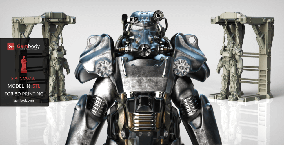
This 3D figurine of T-60 Power Armor consists of files in StereoLithography (.Stl) format that is optimized for 3D printing.
Before printing the files, we strongly recommend reading the PRINTING DETAILS section.
WHAT WILL YOU GET AFTER PURCHASE?
- 9 versions of T-60 Power Armor STL files for FFF/FDM, DLP/SLA, DLP/SLA Eco, SLS - files for all versions are available for download after the purchase;
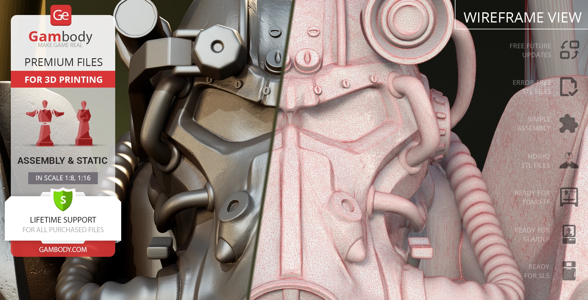
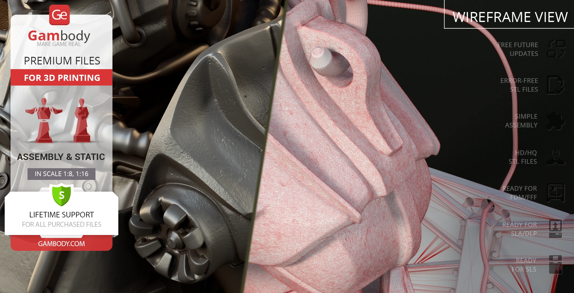
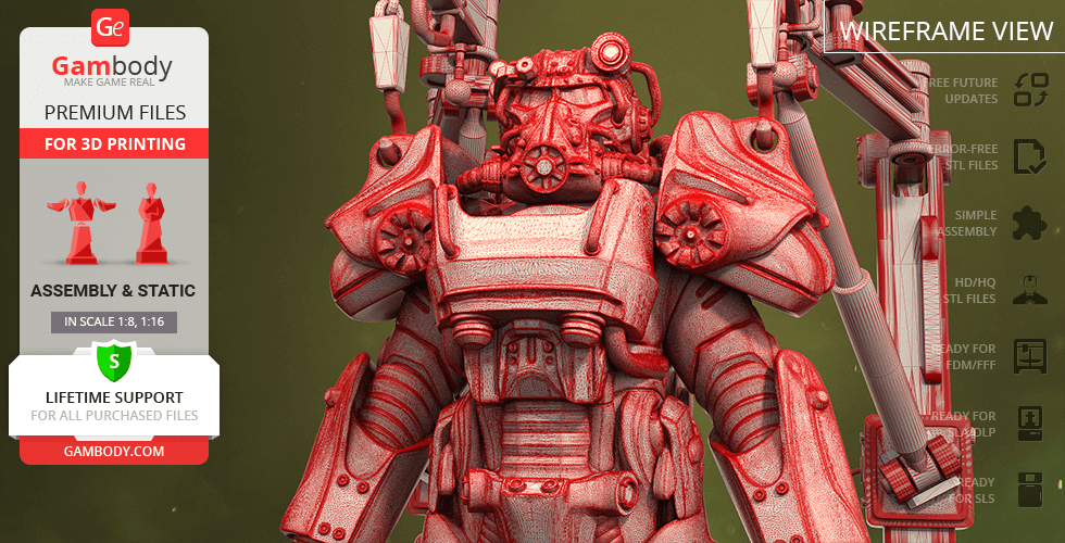
- STL files of high-poly T-60 Power Armor Figurine for 3D printing consist of 155 files;
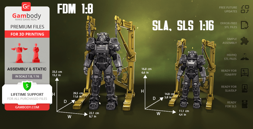
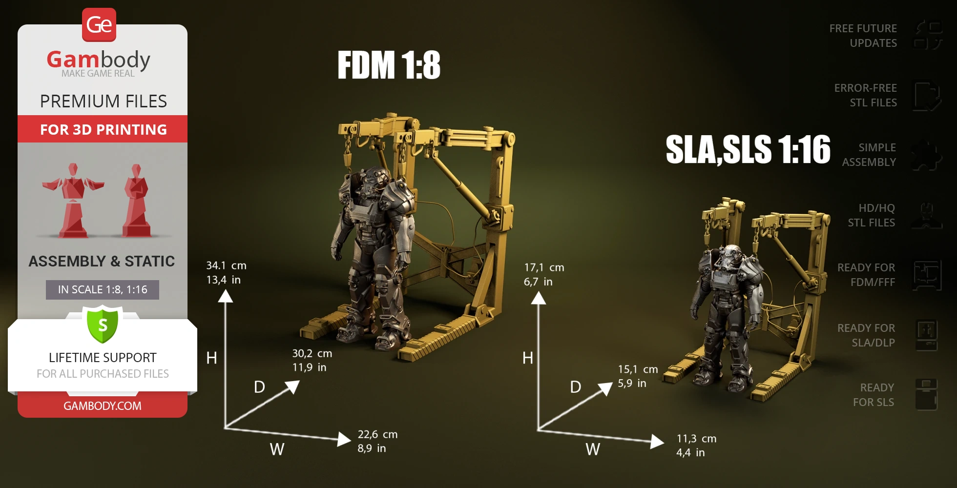
- Sizes for:
- FFF/FDM: 341 mm tall, 226 mm wide, 302 mm deep;
- DLP/SLA/SLS: 171 mm tall, 113 mm wide, 151 mm deep;
- Assembly Manual for FFF/FDM 2.0 and DLP/SLA 2.0 versions in PDF and video formats;
- Detailed settings that we provide as a recommendation for Cura, Simplify3D, Slic3r and PrusaSlicer for the best print;
- Full technical support from the Gambody Support Team.
Detailed information about this 3D printing model is available in the DESCRIPTION section.
Before printing, take a look at Printing Details for recommended settings and tips to achieve better results.
ABOUT THIS 3D MODEL
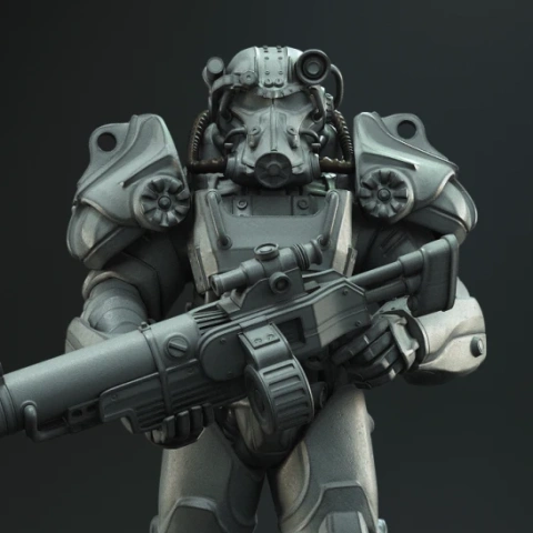
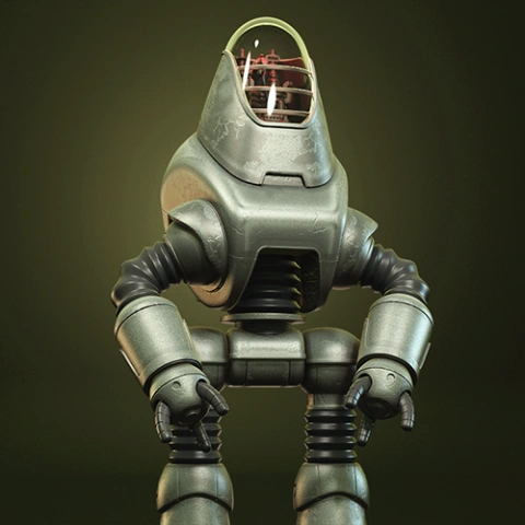
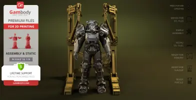
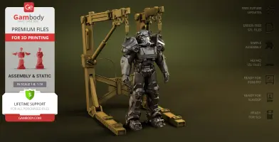
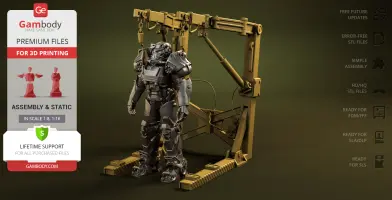
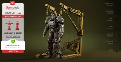
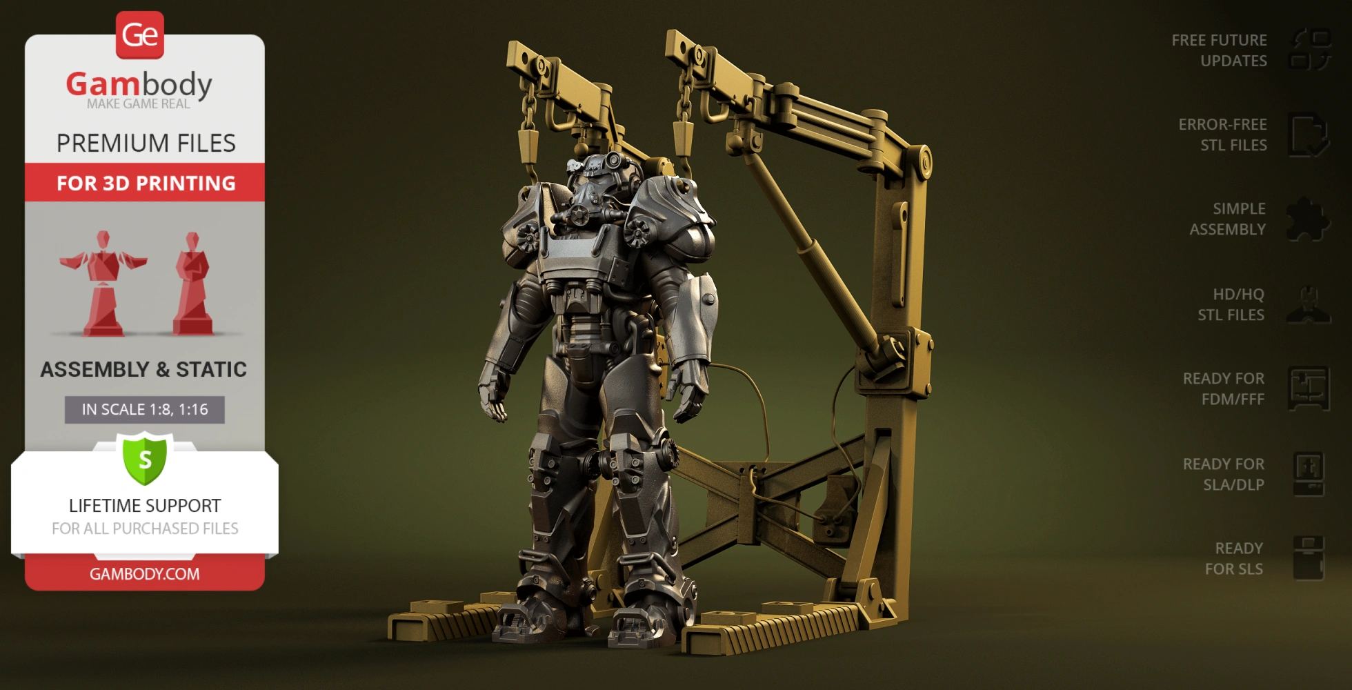
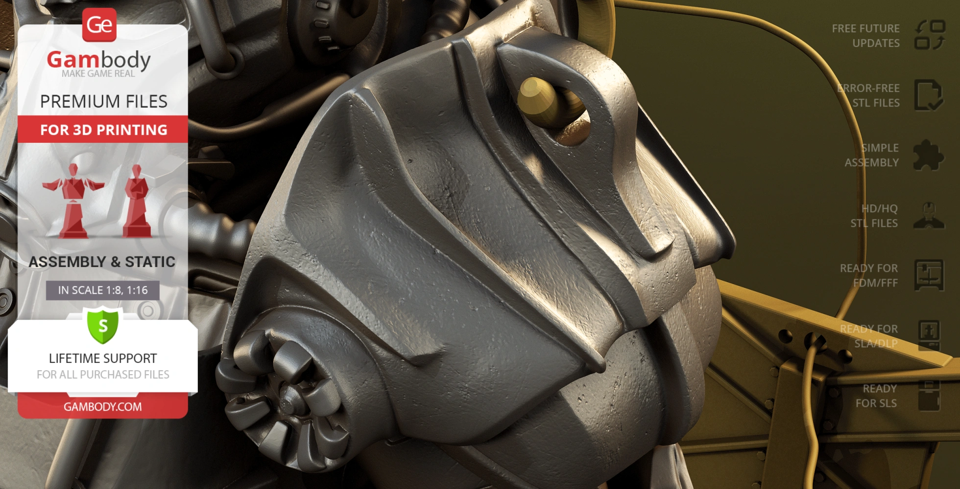
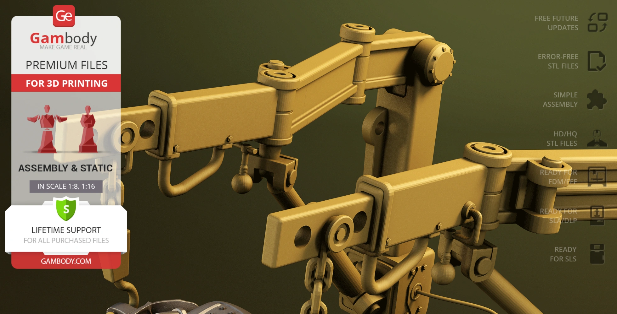
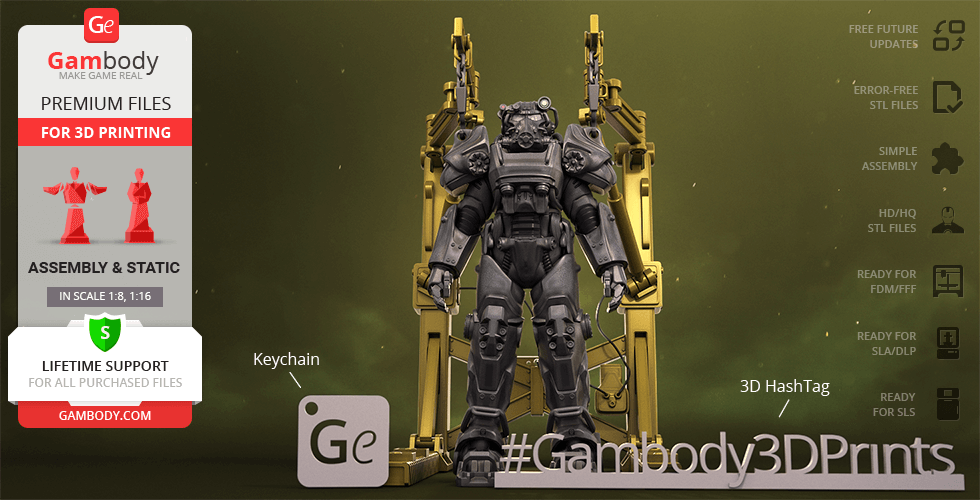
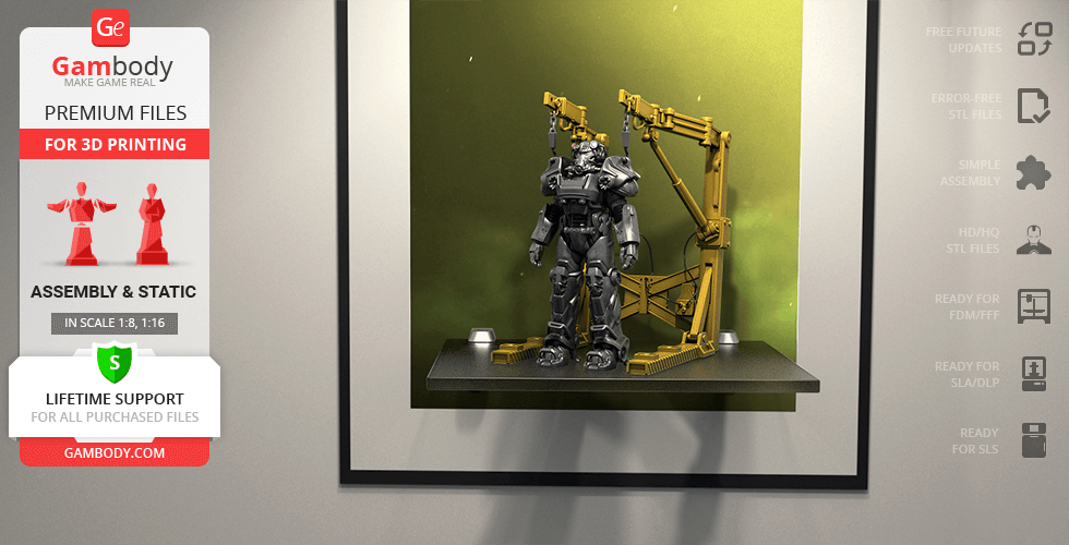
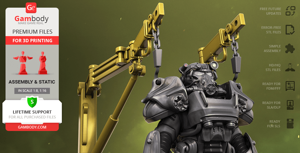
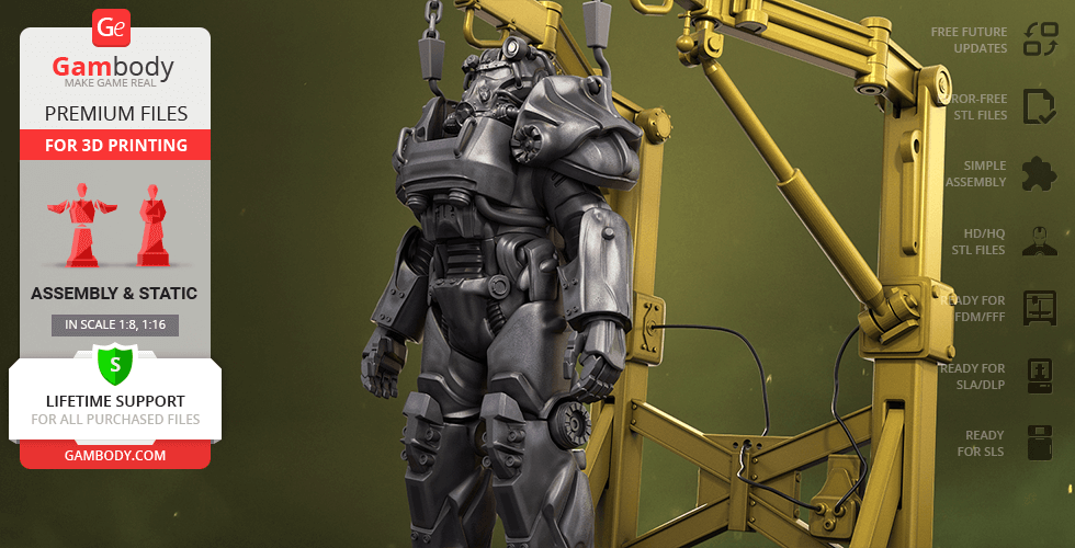
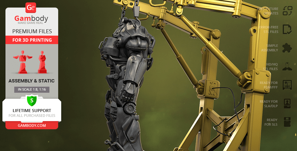
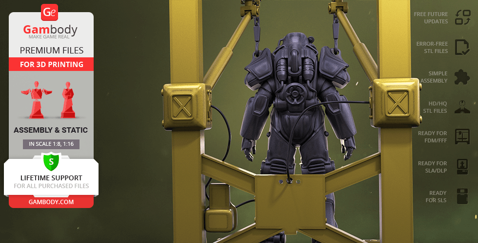
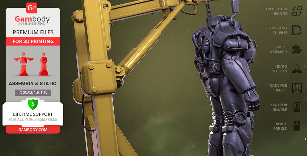
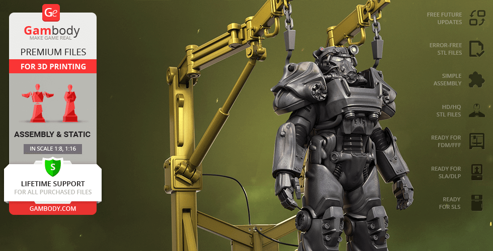
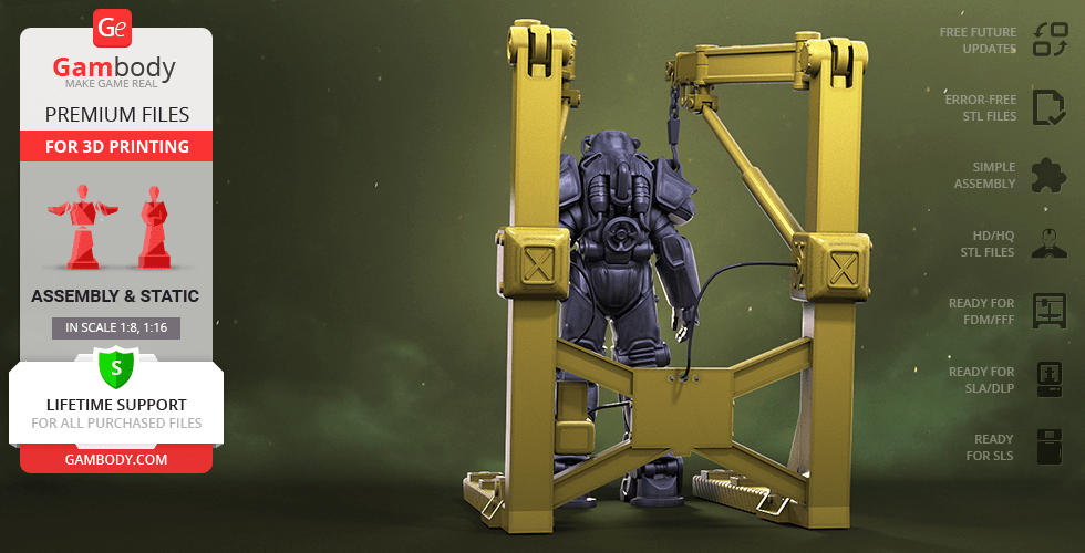
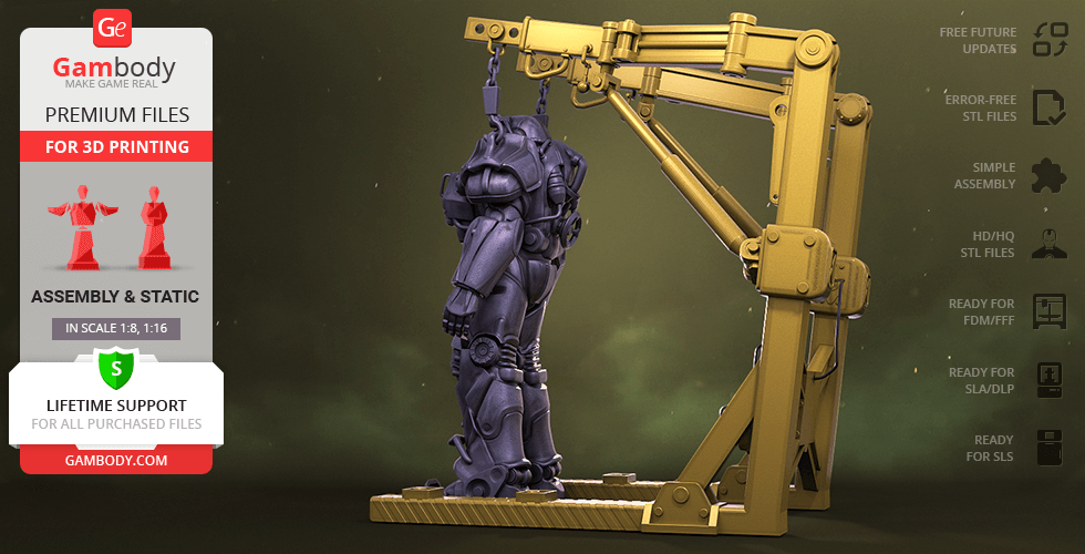
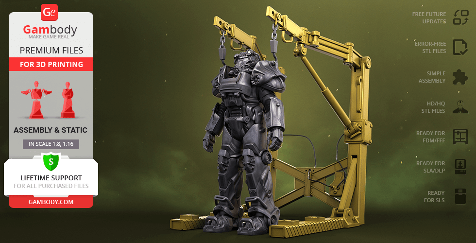
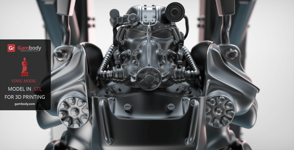
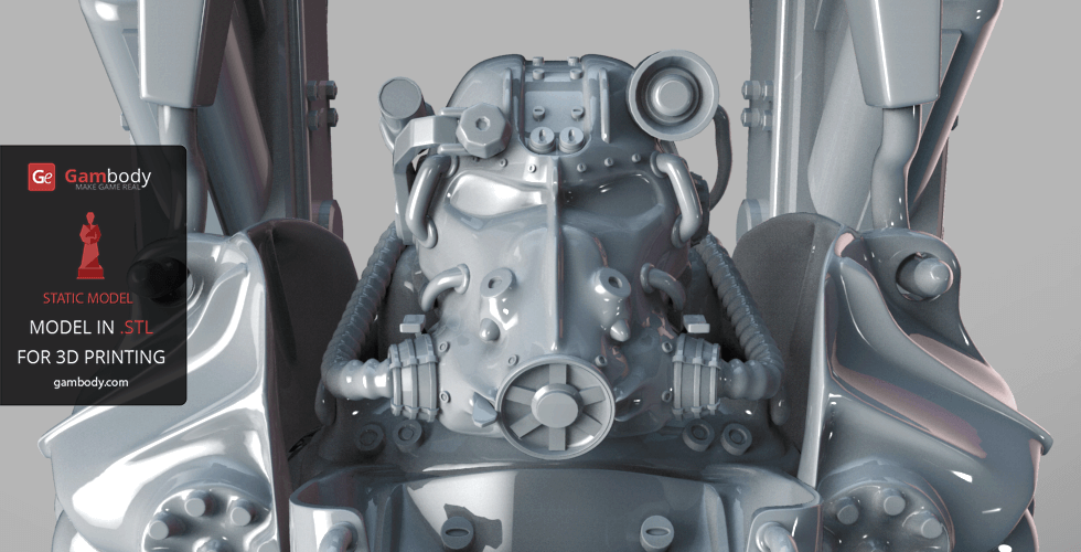
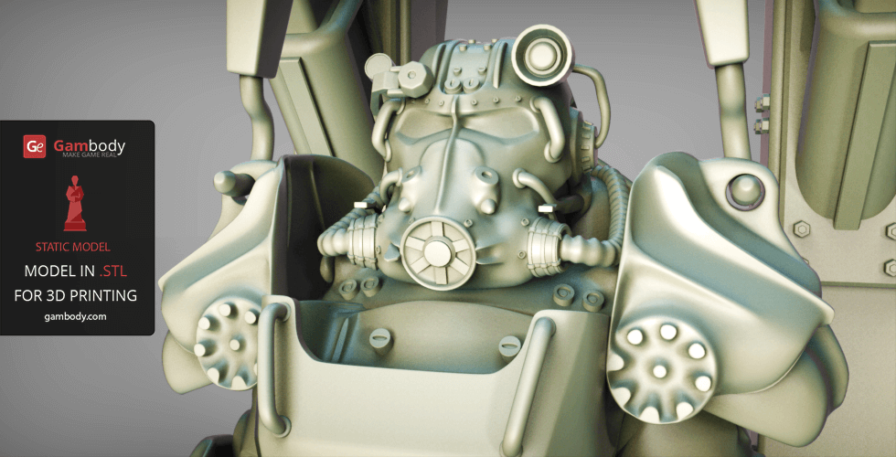
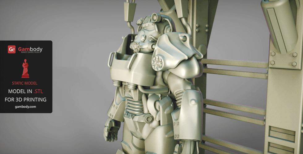
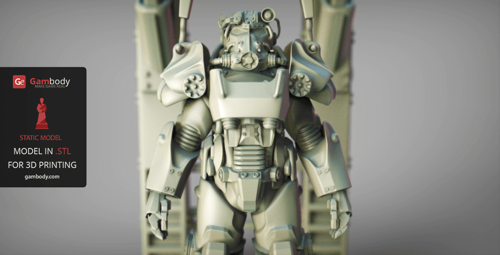
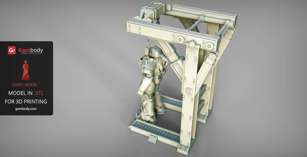
T-60 Power Armor is a wearable external armor, an exoskeleton that the Sole Survivor can either find or craft in the course of the Fallout 4 video game. Once completed, Power Armor guarantees radiation protection, increases strength, and retains the mobility of the playable character at the same time. Have you been looking for a location to find a complete T-60 Power Armor? We've got it on Gambody marketplace in the form of STL files that you can download and 3D print!
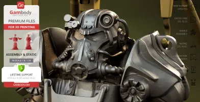
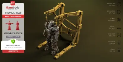
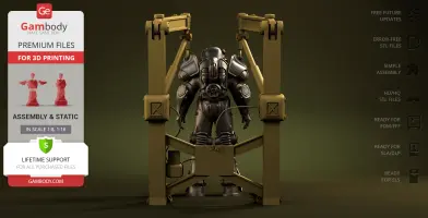
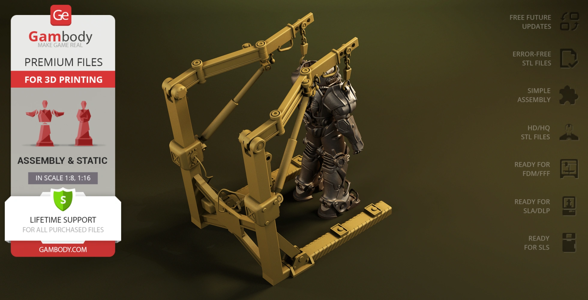
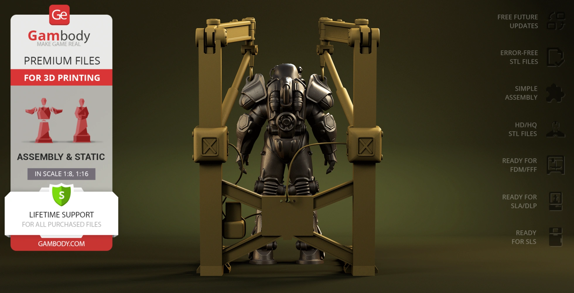
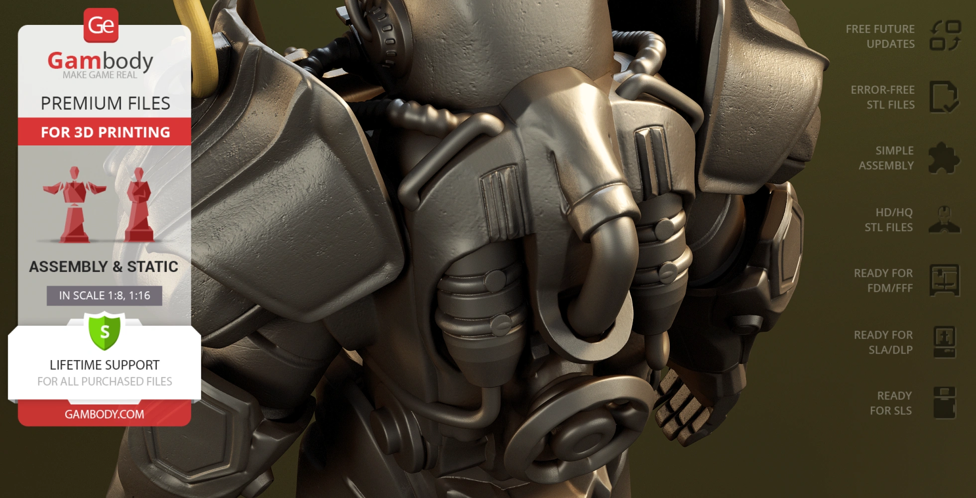
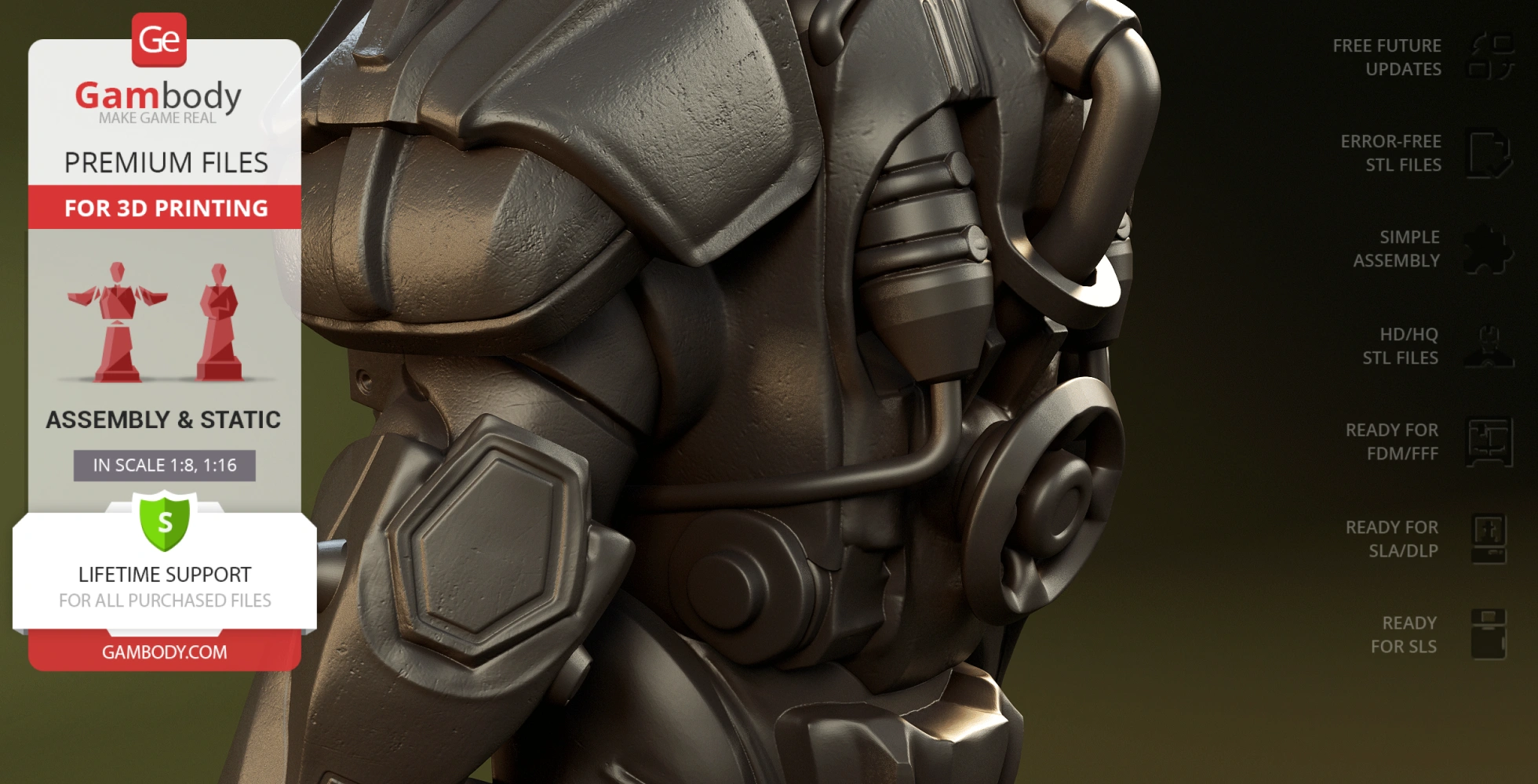
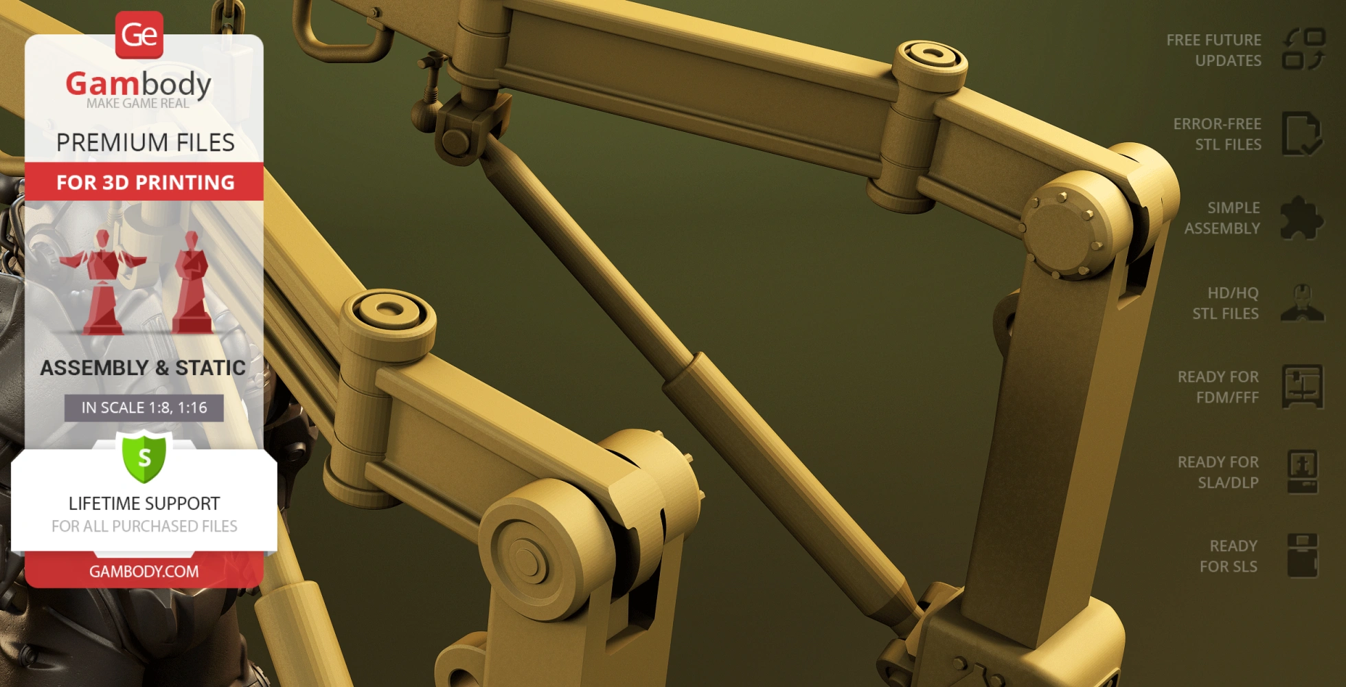
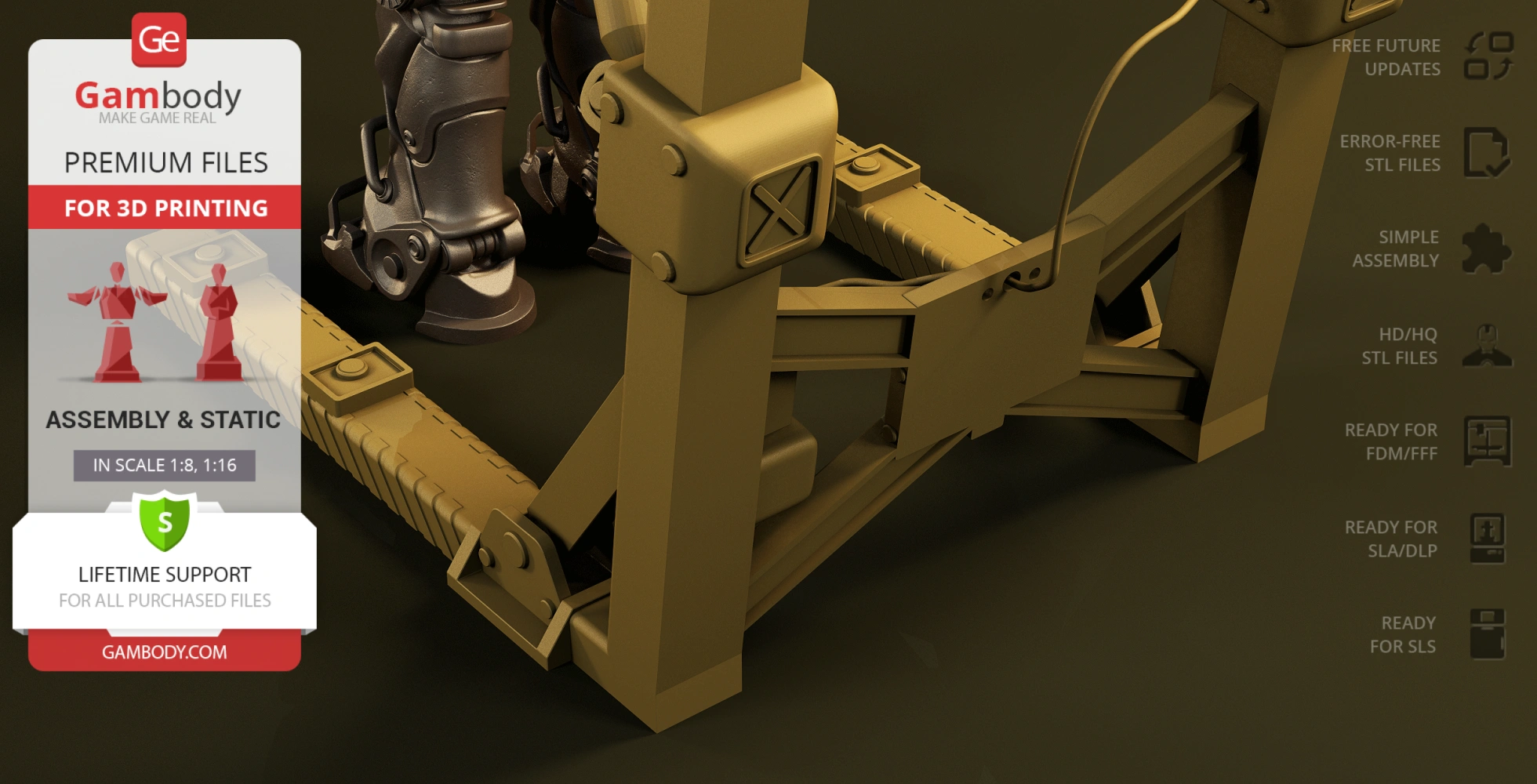
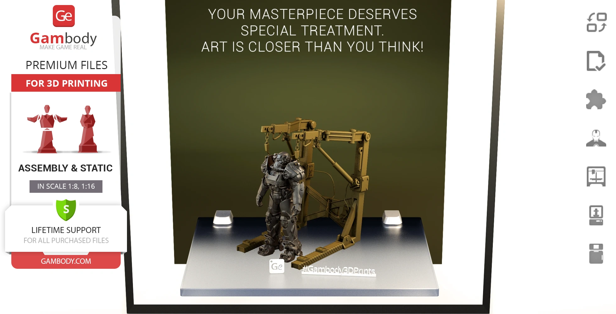
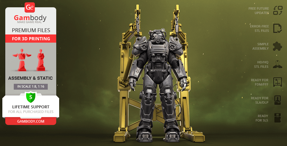
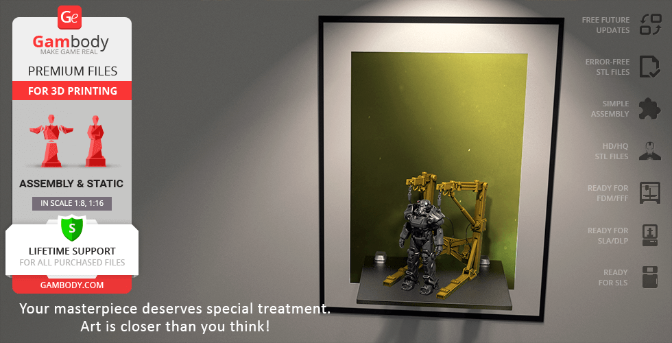
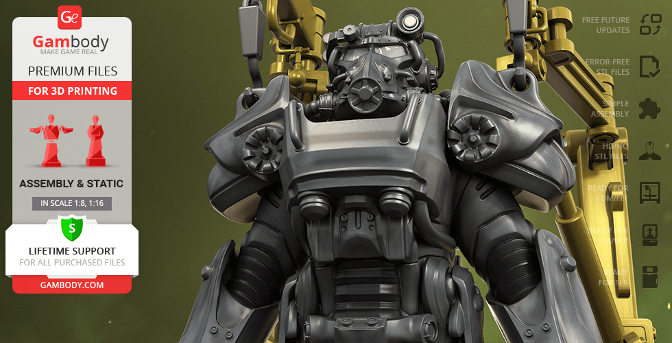
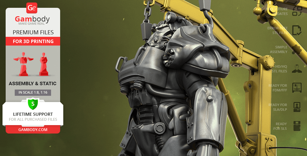
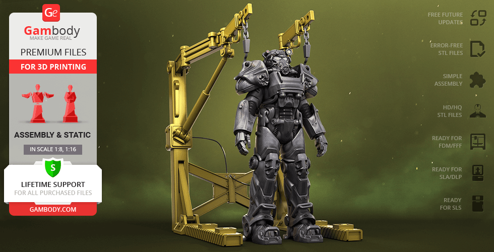
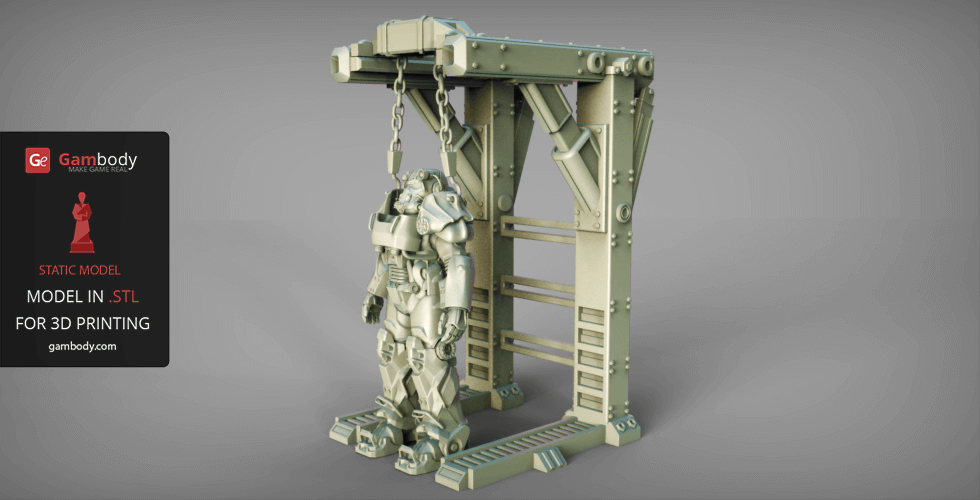
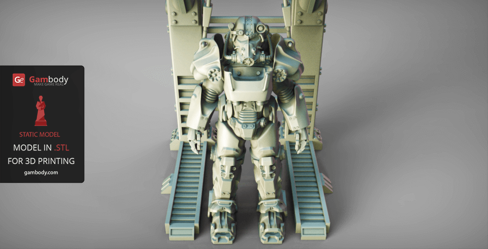
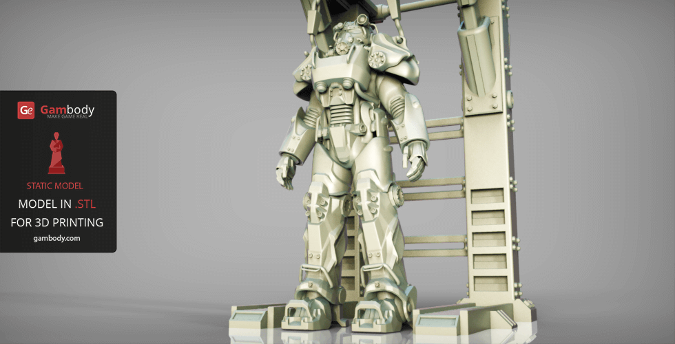
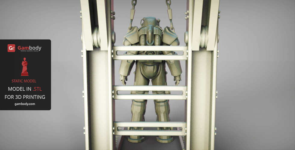
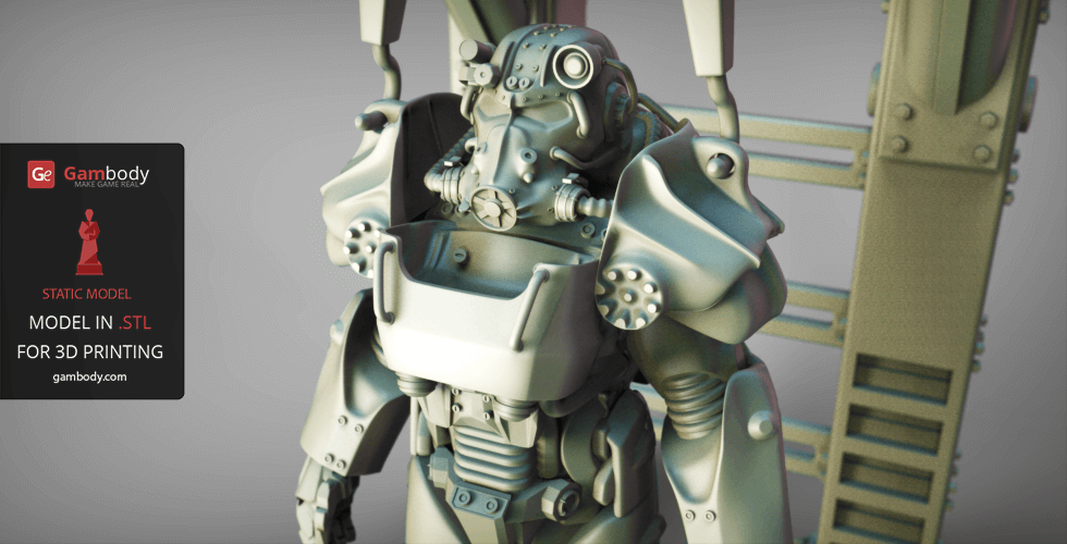
The author of this Power Armor model must truly be a Fallout enthusiast since he went even further and prepared a Power Armor Station for you to display the model as if in the middle of a workshop of Brotherhood of Steel. Once printed and assembled the bulky T-60 can be attached to the hooks on the Station and hang there as if in expectation either of repair or of the Sole Survivor to step into. The 3D printing Power Armor is made taking into account all fine elements that distinguish the large T-60 from other Armor variations. It may not be the most agile option due to its imposing size but nevertheless, the T-60 is a highly desirable aim of any in-game adventurer. It's not a Fallout without Power Armor, so we are pretty sure this power suit for 3D printing is a model any fan of the renowned video game will want to add to the collection. Fortunately, the STL files to print the T-60 are just a click away!
ADAPTATION FOR 3D PRINTING
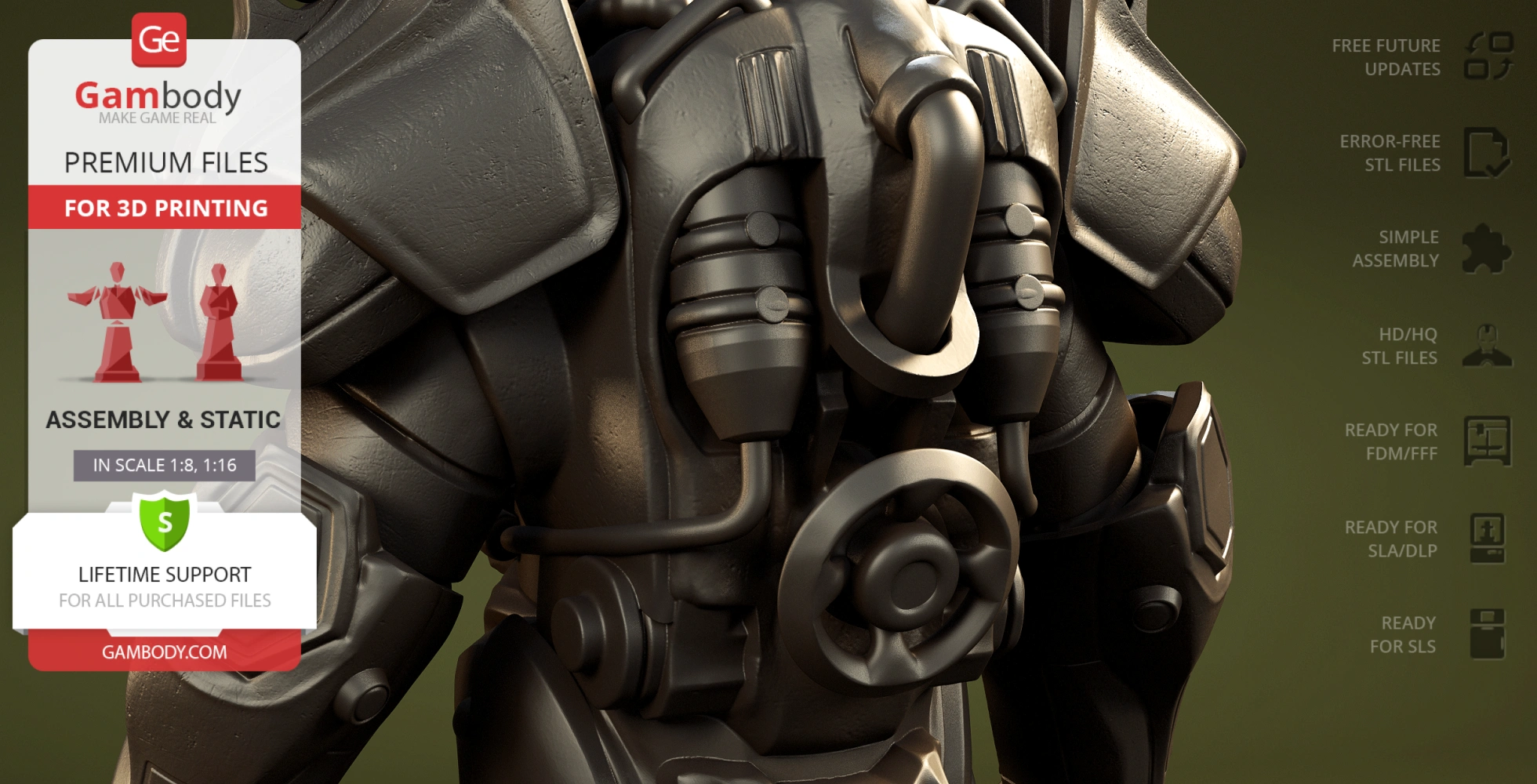
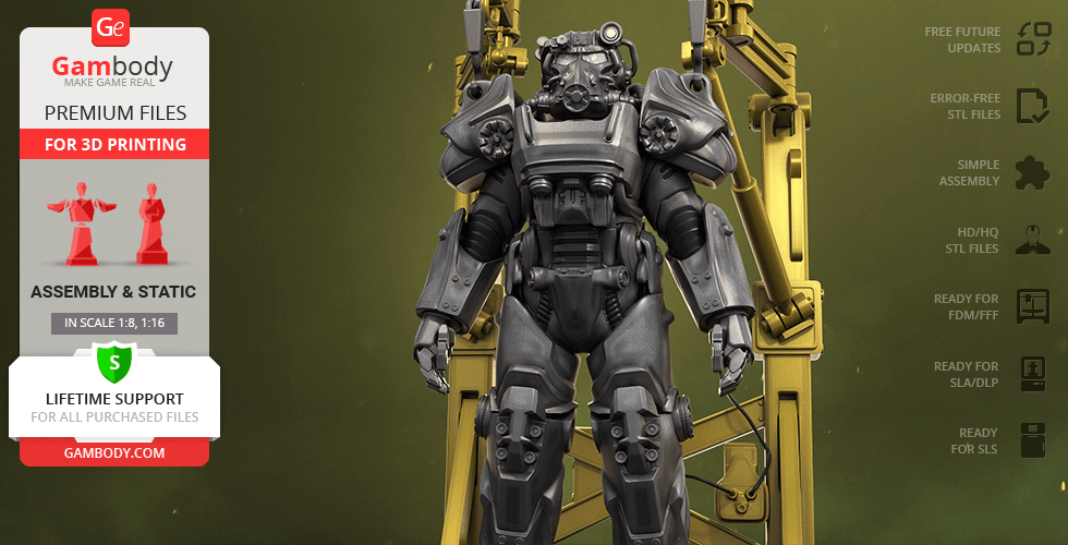
T-60 Power Armor for 3D printing is a static assembly model and its moderation and adaptation for different types of 3D printers took the Gambody team 76 hours in total. The figurines' anatomy and proportions were thoroughly reviewed during the moderation process for the suit to be depicted harmoniously in the intended pose.
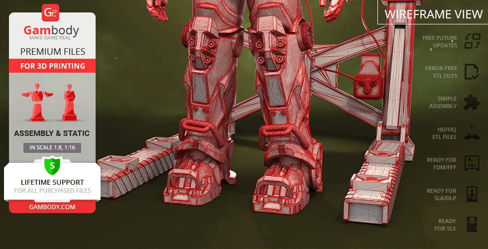
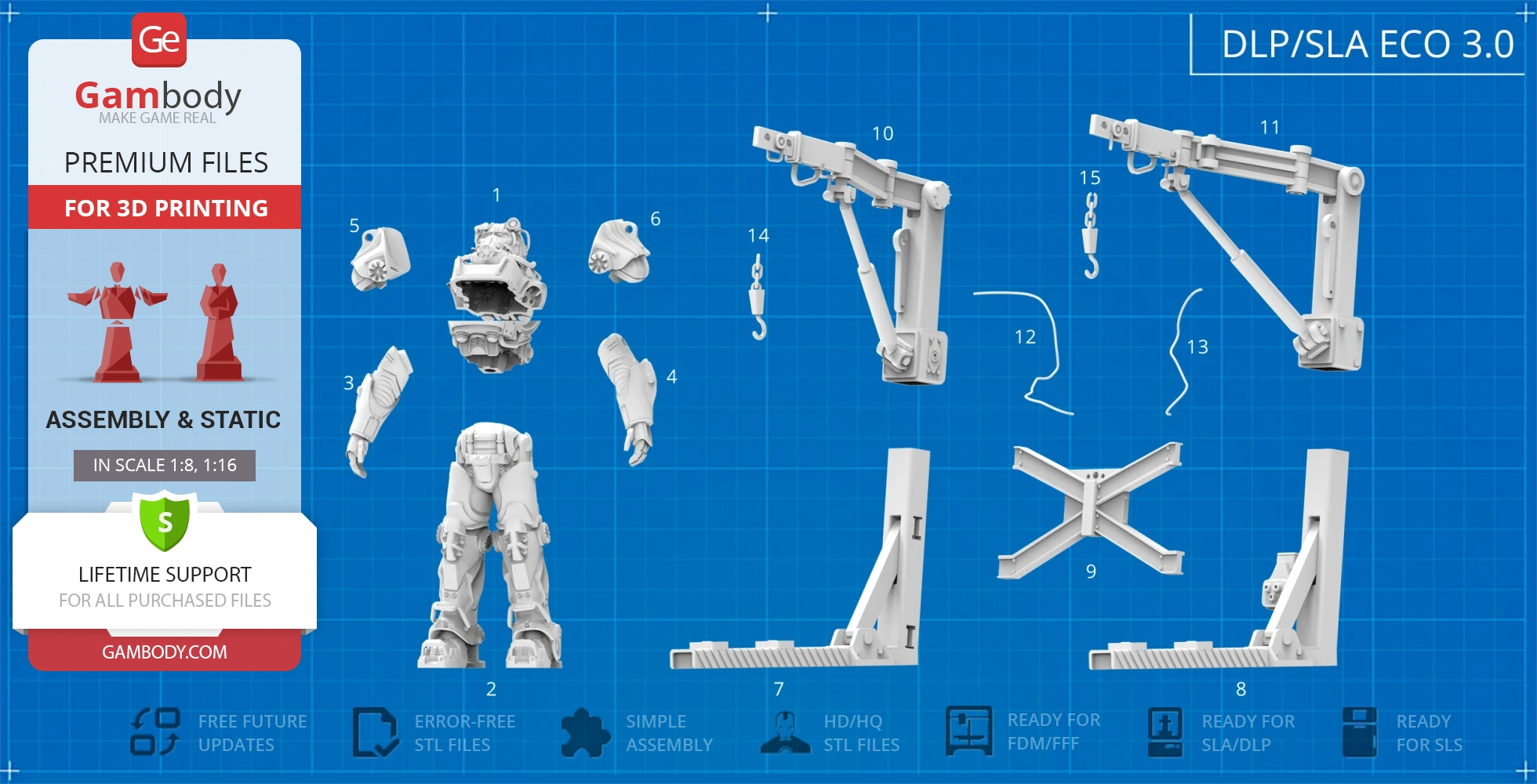
The figurine’s cutting was chosen by our team to minimise the amount of generated support and some of the parts were hollowed out for you to save resin in the Eco version. In order to conceal the places where the assembly parts of the figurine are connected, T-60 Power Armor was divided into convenient assembly parts.
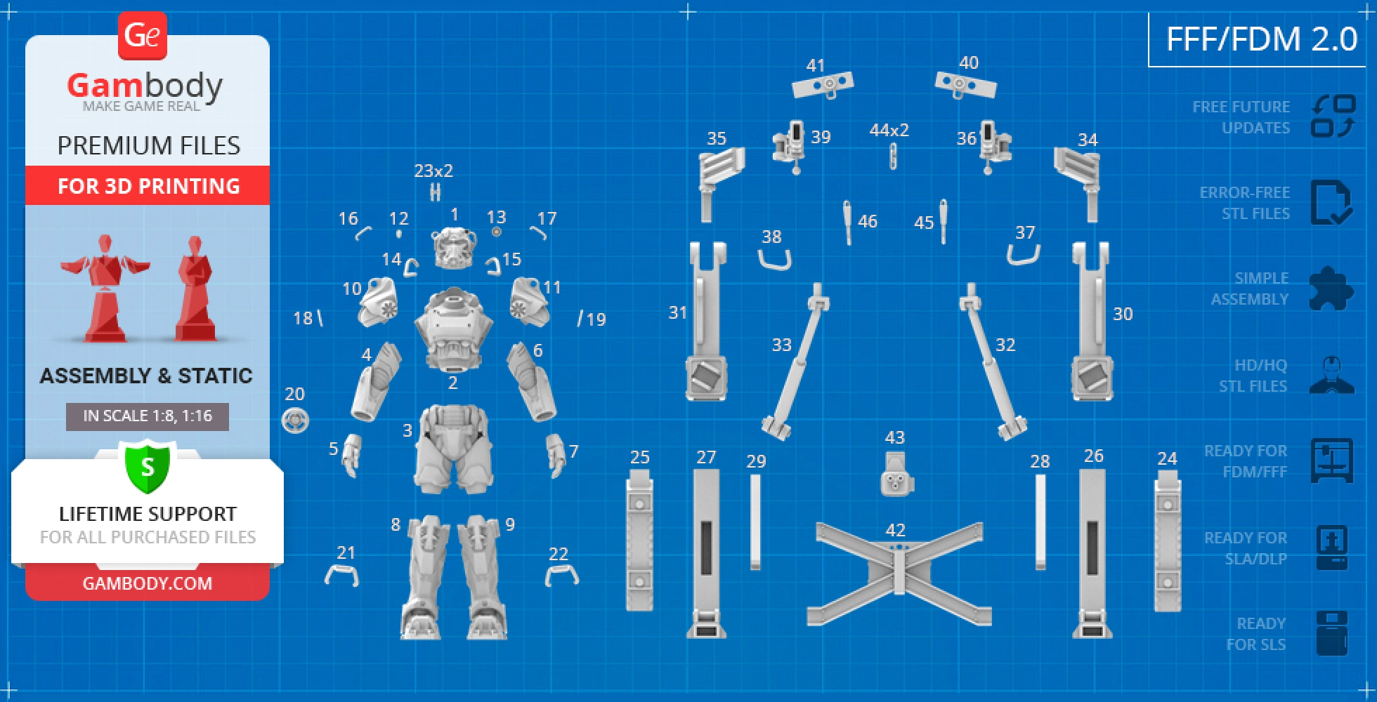
All assembly parts in the FFF/FDM 2.0 version are provided in STL files in recommended positions that were worked out in order to ensure the smoothness of the details’ surfaces after printing and that the 3D printing beginners won't face difficulties when placing the parts on a build plate. When downloading any model's file you will also receive "Assembly Manual" for FFF/FDM 2.0 and DLP/SLA 2.0 versions in PDF format. We highly recommend that you get acquainted with the “Assembly Video” and "Assembly Manual" before getting down to T-60 Power Armor.
The model is saved in STL files, a format supported by most 3D printers. All STL files for 3D printing have been checked in Netfabb and no errors were shown.
The figurine’s scale was calculated from the height of T-60 Power Armor which is 2200 mm. The 3D printing figurine’s chosen scales are 1:8 for the FFF/FDM version and 1:16 for the DLP/SLA/SLS versions.
VERSIONS’ SPECIFICATIONS
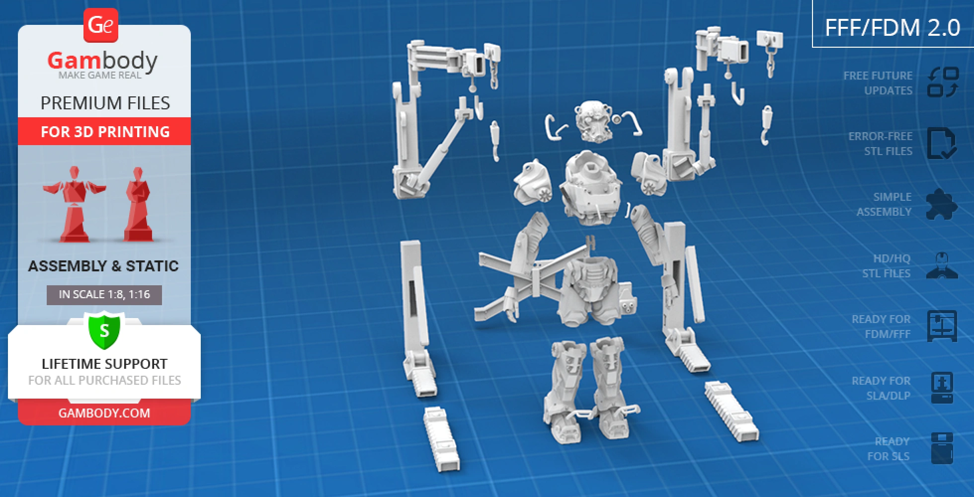
FFF/FDM 2.0 version features:
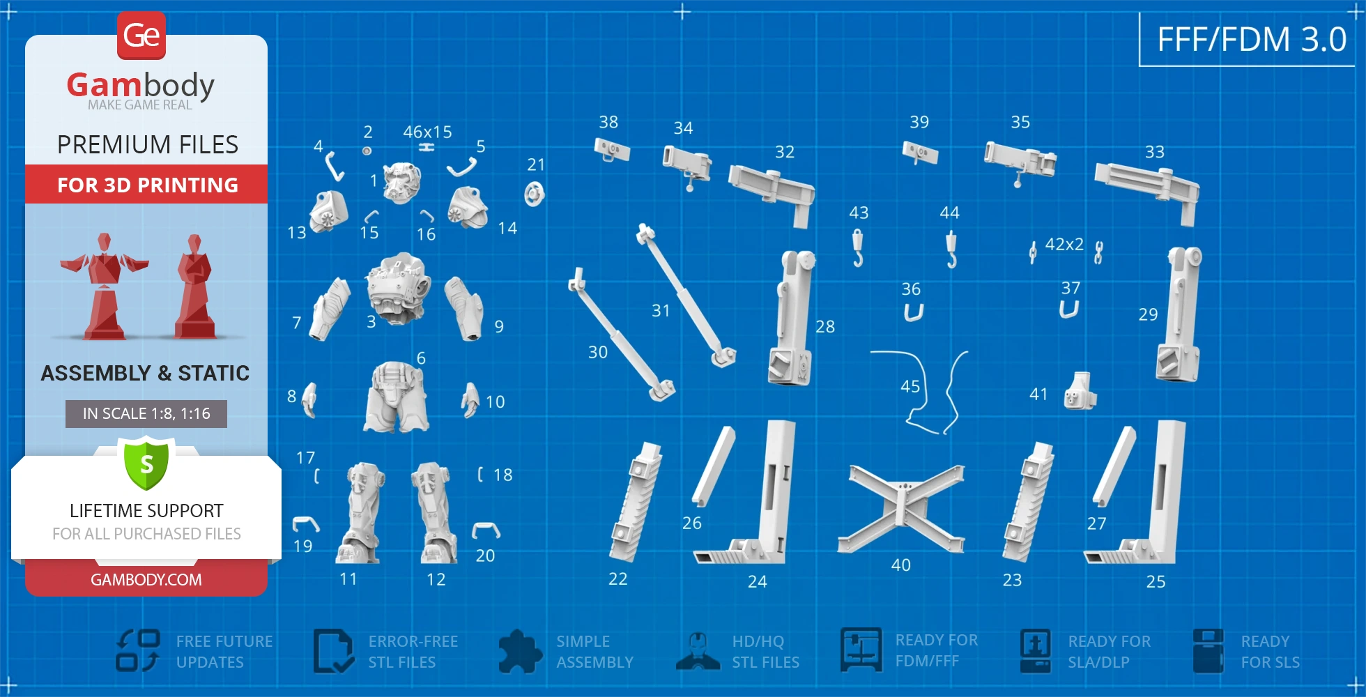
- Contains 46 parts;
- A printed figurine is 341 mm tall, 226 mm wide, 302 mm deep;
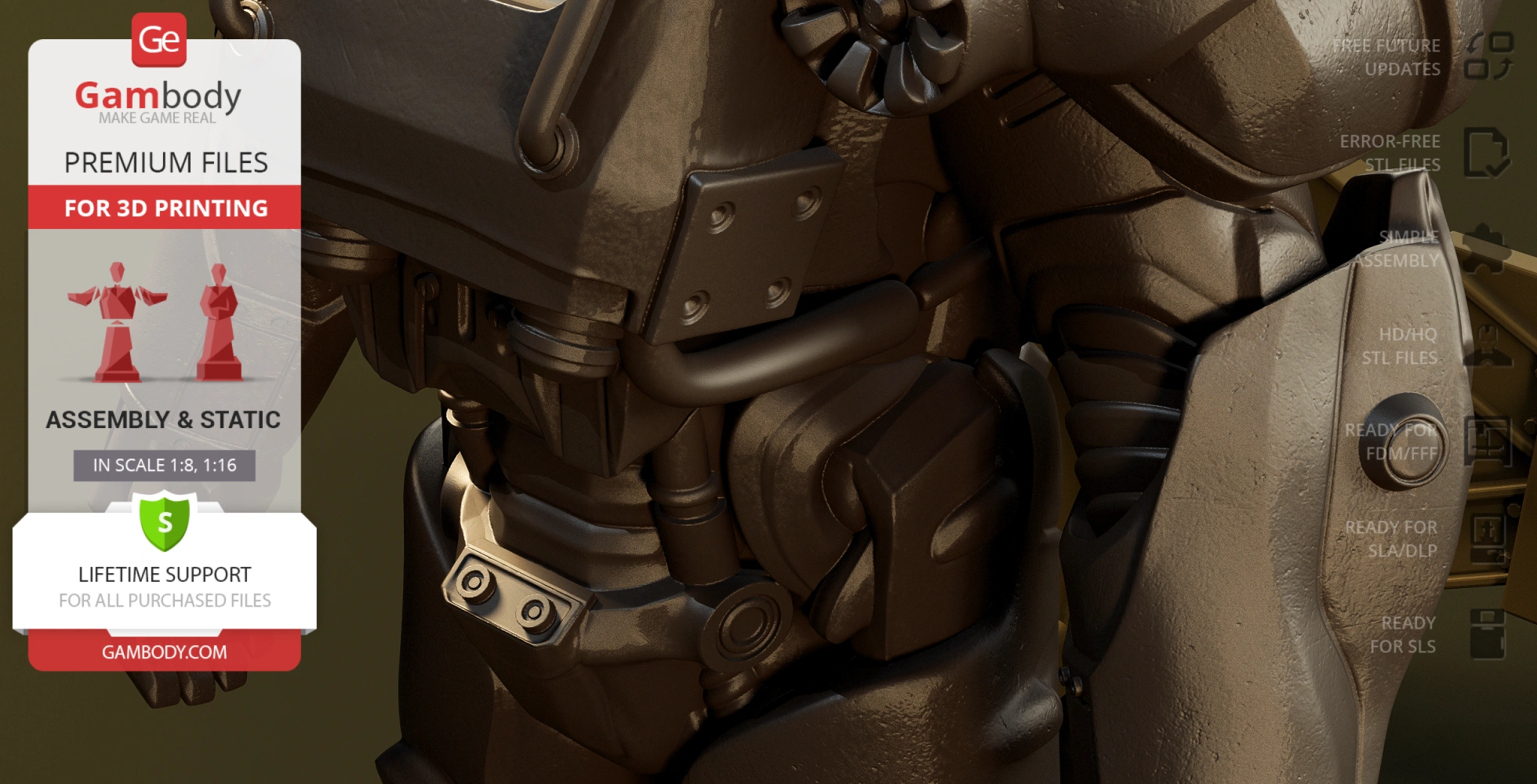
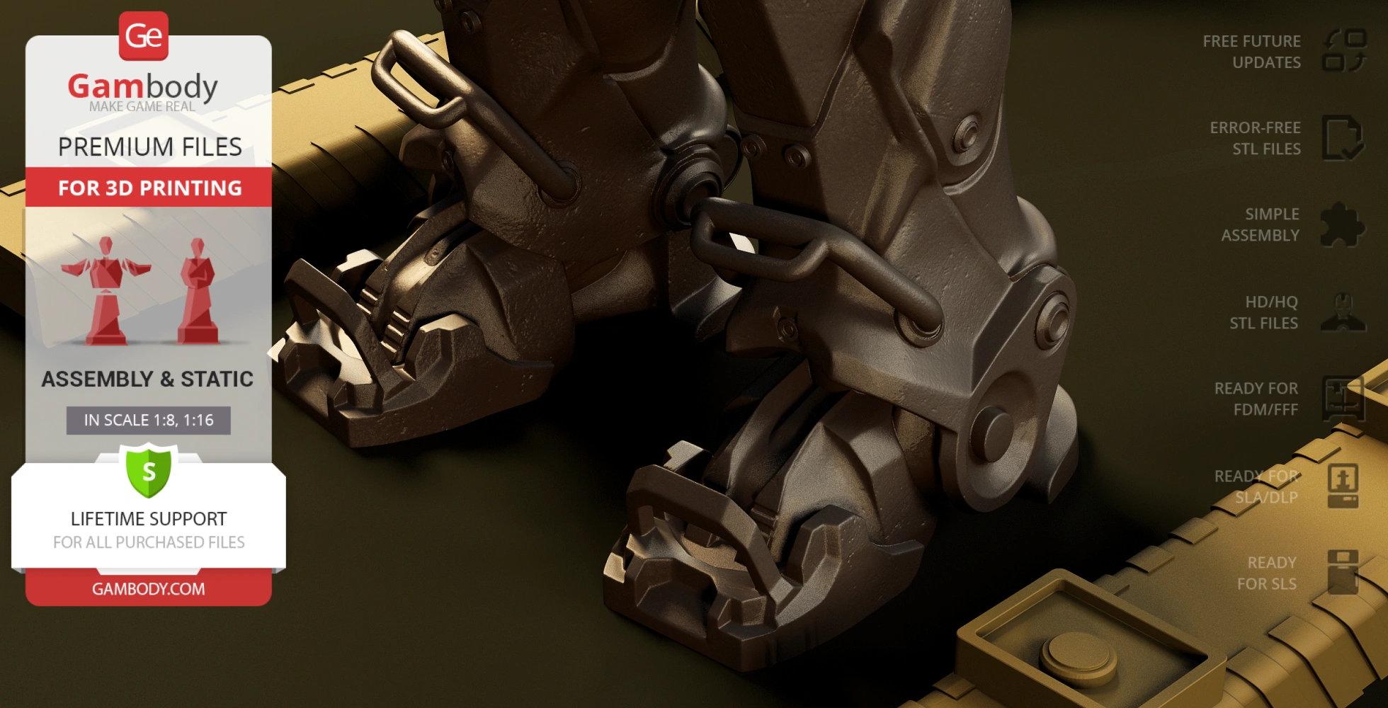
- Upgraded design - enhanced level of detail, reworked proportions.
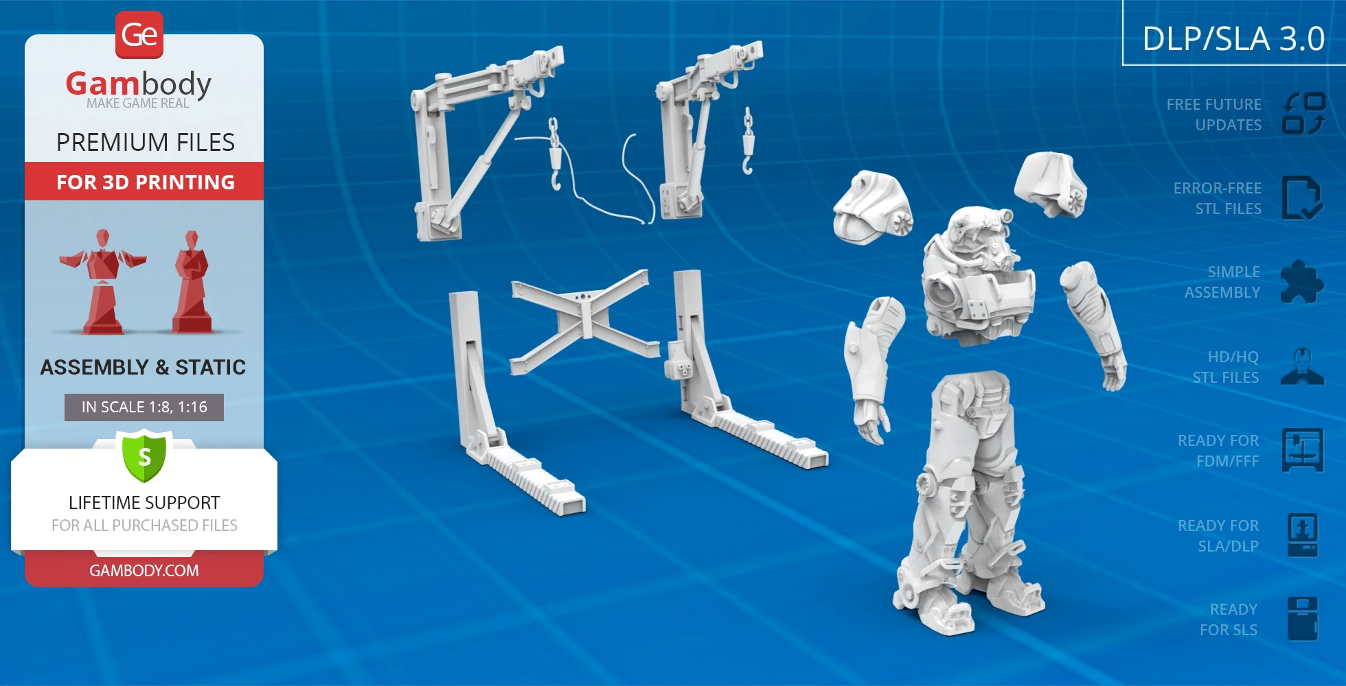
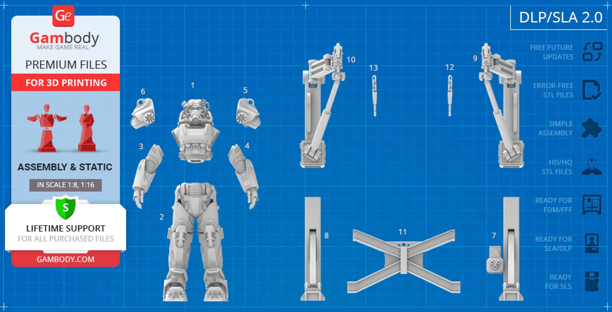
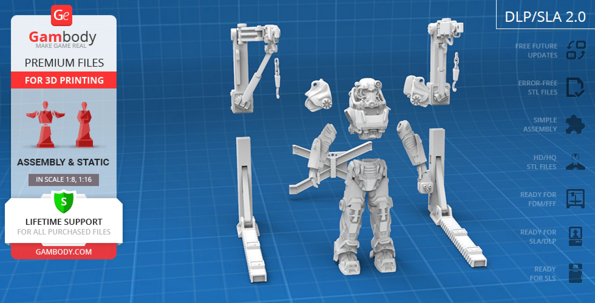
DLP/SLA 2.0 version features:
- Contains 15 parts;
- A printed figurine is 171 mm tall, 113 mm wide, 151 mm deep;
- Upgraded design - enhanced level of detail, reworked proportions.
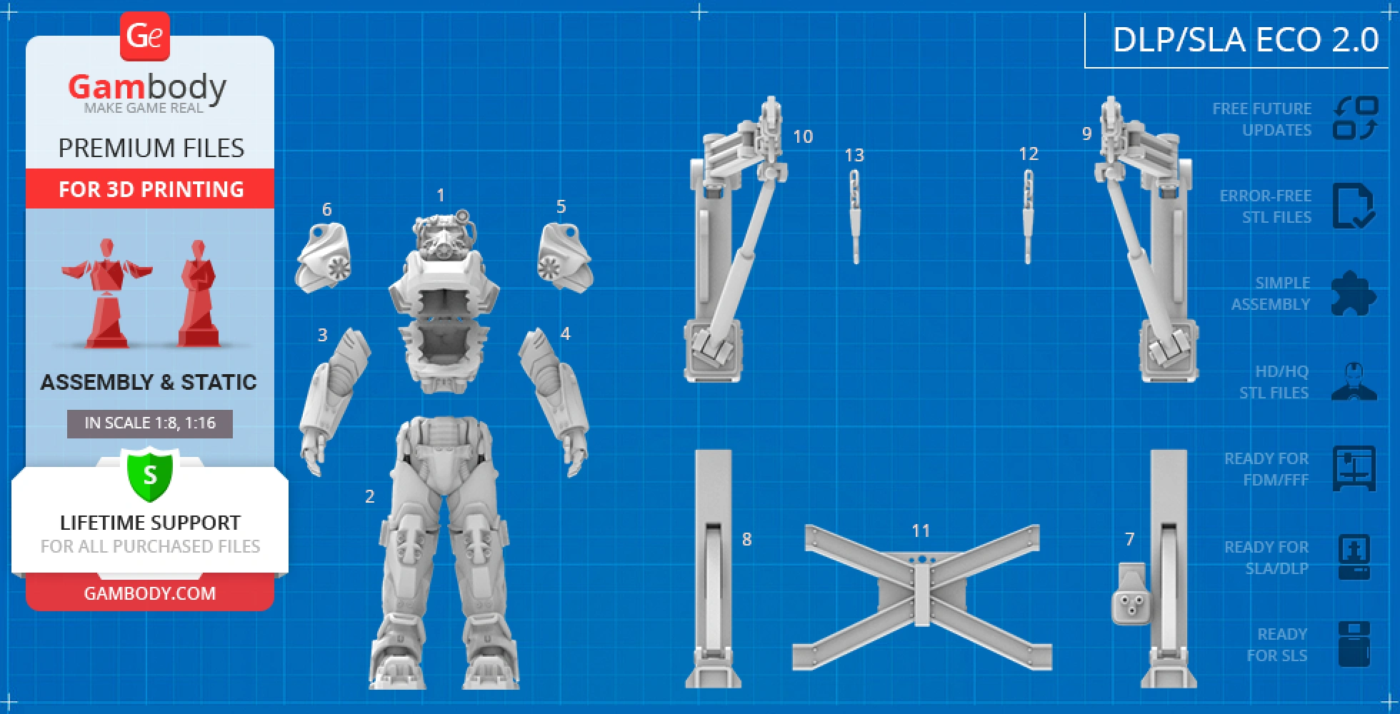
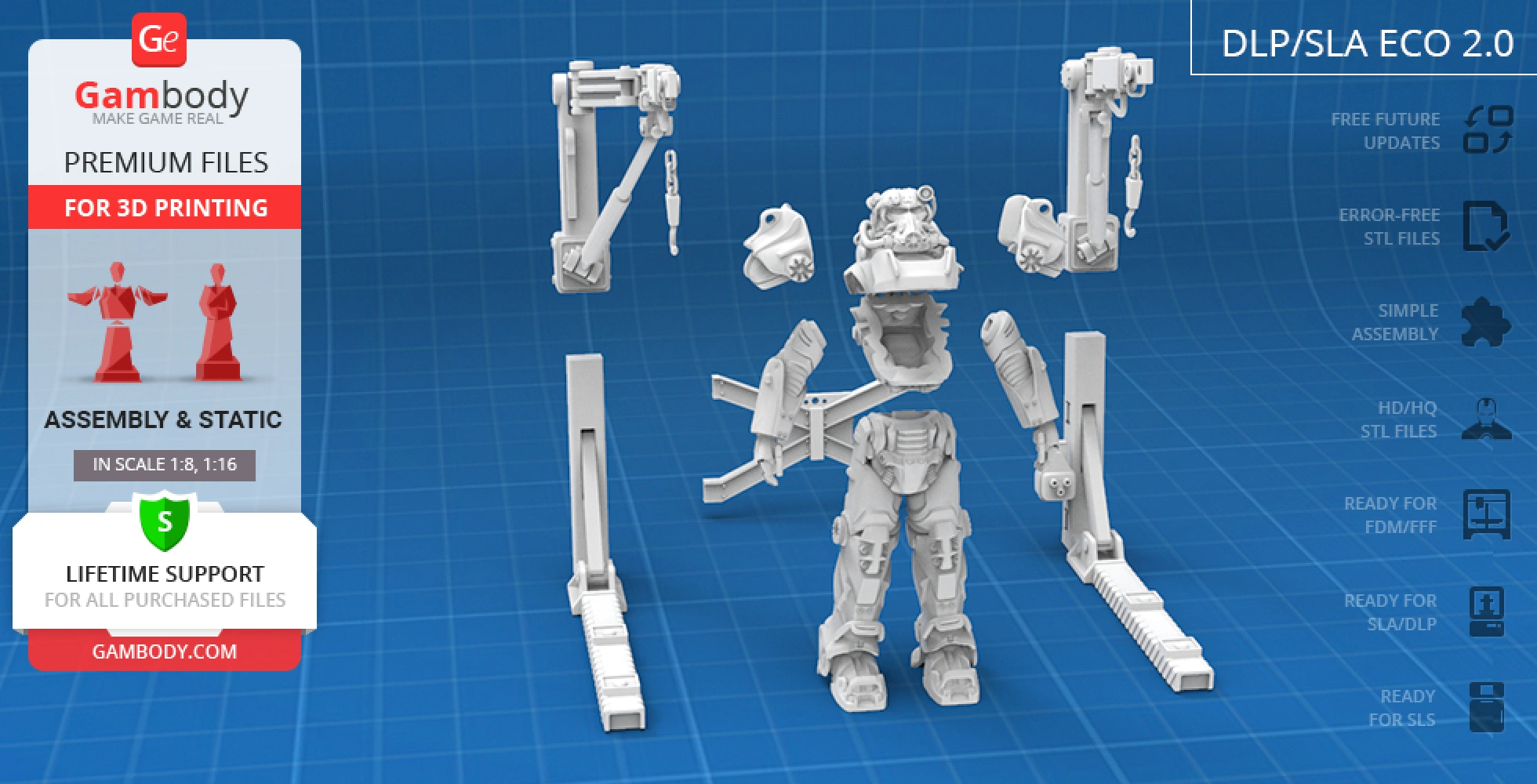
DLP/SLA Eco 2.0 version features:
- Contains 13 parts;
- A printed figurine is 171 mm tall, 113 mm wide, 151 mm deep;
- Upgraded design - enhanced level of detail, reworked proportions.
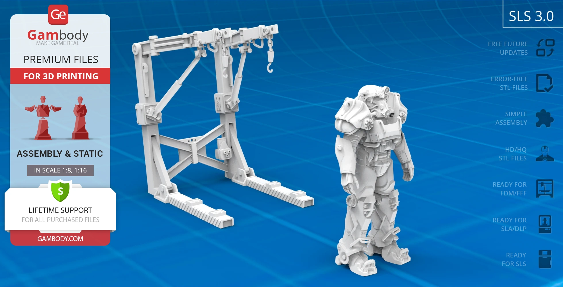
SLS 3.0 version features (Coming Soon):
- Contains 2 parts - a solid Power Armor figurine and a platform;
- A printed figurine is 171 mm tall, 113 mm wide, 151 mm deep;
- Upgraded design - enhanced level of detail, reworked proportions.
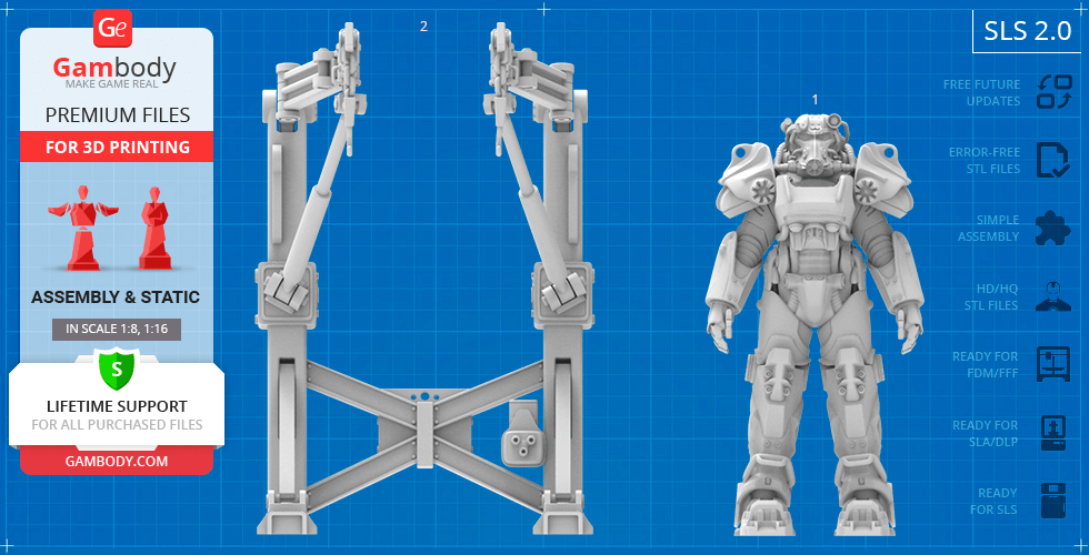
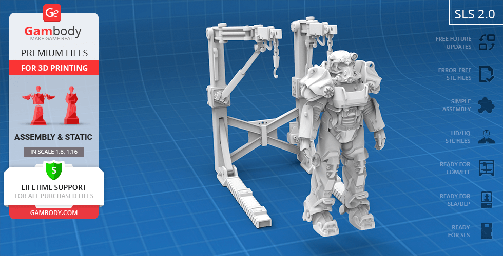
SLS 2.0 version features:
- Made as a solid one-piece figurine;
- A printed model is 168 mm tall, 111 mm wide, 148 mm deep;
- Introduced new cutting and significantly enhanced level of detail;
- Contains 2 parts - a one-piece model with the platform separated.
FFF/FDM 1.0 version features:
- Contains 46 parts;
- A printed model is 335 mm tall, 221 mm wide, 295 mm deep;
- Assembly kit includes lock 23_ge_lock_10H(x2) to connect parts securely without glue that needs to be printed twice;
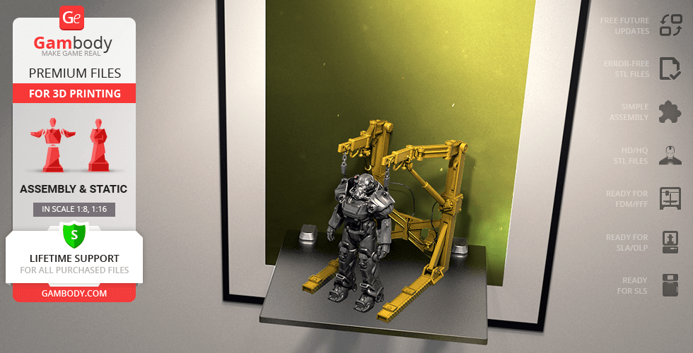
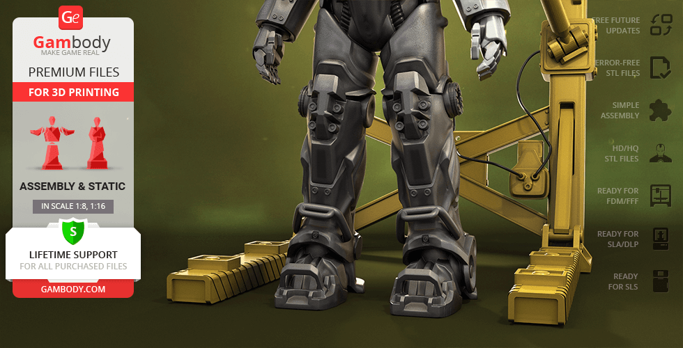
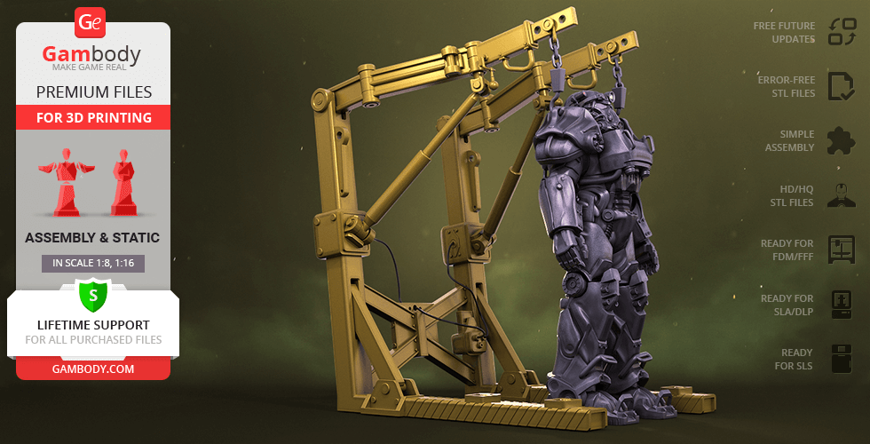
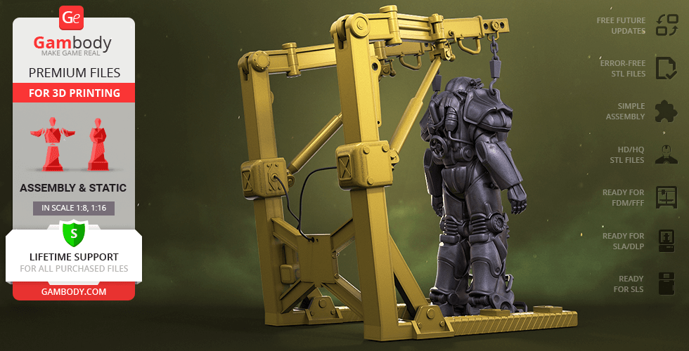
- Made with a Power Armor Station platform where it can be displayed hung on a pair of hooks;
- Wires that connect the hydraulic pistons of the Power Armor Station are not provided with STL files - we recommend that you use 2.85 mm flexible filament or simple 2.85/1.75mm PLA plastic;
- All parts are divided in such a way that you will print them with the smallest number of support structures.
DLP/SLA 1.0 version features:
- Contains 13 parts;
- A printed model is 168 mm tall, 111 mm wide, 148 mm deep;
- Made with a Power Armor Station platform where it can be displayed hung on a pair of hooks;
- Wires that connect the hydraulic pistons of the Power Armor Station are not provided with STL files - we recommend that you use 2.85mm flexible filament or simple 2.85/1.75mm PLA plastic;
- All parts are divided in such a way to fit the build plates and to ensure that support structures are generated where needed.
DLP/SLA Eco 1.0 version features:
- Contains 13 parts;
- A printed model is 168 mm tall, 111 mm wide, 148 mm deep;
- Made with a Power Armor Station platform where it can be displayed hung on a pair of hooks;
- Wires that connect the hydraulic pistons of the Power Armor Station are not provided with STL files - we recommend that you use 2.85mm flexible filament or simple 2.85/1.75mm PLA plastic;
- Contains some hollowed out parts to save resin.
SLS 1.0 version features:
- Contains 3 parts;
- A printed model is 118 mm tall, 171 mm wide, 107 mm deep;
- The scale of the model is indeterminate.
You can get the figurine of T-60 Power Armor Figurine for 3D Printing immediately after the purchase! Just click the green Buy button in the top-right corner of the model’s page. You can pay with PayPal or your credit card.
Watch the tutorial on how to assemble T-60 Power Armor 3D Printing Figurine onGambody YouTube channel.
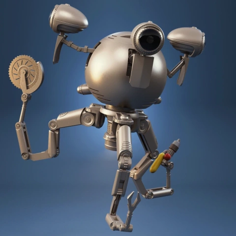
Also, you may like the Codsworth3D Printing Model and other Video Game3D Printing Models.
_______
FAQ:
Average customer rating (27 reviews)
4.8
Ratings breakdown
Click a star rating to filter reviews
Overall experience
Level of detail in the model
4.8
Model cut quality and assembly guide
4.8
Clarity and accuracy of the model page
4.8
Level of detail in the model
5
Model cut quality and assembly guide
5
Clarity and accuracy of the model page
5
Level of detail in the model
5
Model cut quality and assembly guide
5
Clarity and accuracy of the model page
5
If you don’t mind, we would be grateful if you could let us know whether there were any specific points that influenced your overall rating of the model. We always strive to ensure that the ratings and reviews on Gambody reflect users’ experience as accurately as possible.
Thank you for choosing Gambody.
Level of detail in the model
4.7
Model cut quality and assembly guide
4.8
Clarity and accuracy of the model page
5
Level of detail in the model
5
Model cut quality and assembly guide
5
Clarity and accuracy of the model page
5
Level of detail in the model
5
Model cut quality and assembly guide
5
Clarity and accuracy of the model page
5
Level of detail in the model
3
Model cut quality and assembly guide
3
Clarity and accuracy of the model page
3
Level of detail in the model
5
Model cut quality and assembly guide
5
Clarity and accuracy of the model page
5
Level of detail in the model
5
Model cut quality and assembly guide
5
Clarity and accuracy of the model page
5
Level of detail in the model
5
Model cut quality and assembly guide
5
Clarity and accuracy of the model page
5
Level of detail in the model
3
Model cut quality and assembly guide
3
Clarity and accuracy of the model page
3
Level of detail in the model
5
Model cut quality and assembly guide
5
Clarity and accuracy of the model page
5
Level of detail in the model
5
Model cut quality and assembly guide
5
Clarity and accuracy of the model page
5
Level of detail in the model
5
Model cut quality and assembly guide
5
Clarity and accuracy of the model page
5
Level of detail in the model
5
Model cut quality and assembly guide
5
Clarity and accuracy of the model page
5
Level of detail in the model
4
Model cut quality and assembly guide
4
Clarity and accuracy of the model page
4
Level of detail in the model
5
Model cut quality and assembly guide
5
Clarity and accuracy of the model page
5
Level of detail in the model
5
Model cut quality and assembly guide
5
Clarity and accuracy of the model page
5
Level of detail in the model
5
Model cut quality and assembly guide
5
Clarity and accuracy of the model page
5
Level of detail in the model
5
Model cut quality and assembly guide
5
Clarity and accuracy of the model page
5
Level of detail in the model
5
Model cut quality and assembly guide
5
Clarity and accuracy of the model page
5
Below you'll find detailed slicing settings for Bambu Studio 2.0+, Orca Slicer 2.0+, UltiMaker Cura 5.0+, PrusaSlicer 2.0+, Slic3r 1.3+, Simplify3D 5.0+ to help you get the best results when printing this model. These settings are optimized specifically for this 3D model, but please note they may need slight adjustments depending on your printer or filament. When in doubt, refer to your printer's user manual.
To avoid printing issues and achieve the best quality, we highly recommend applying the following settings:
For better quality use 0.12 mm layer height, for fast printing use 0.2 mm layer height. For pins and the Ge connectors, use 0.2 layer height.
120-150% of your Layer Height
But you can paint the seam if you want.
You have to calibrate this parameter
You have to calibrate this parameter
You have to calibrate this parameter
For pins and power elements of the structure, such as the vehicle frame, use 3 loop
Disabled for vehicles and enabled for characters
For 0,2 Layer Height
The parameters in this tab vary greatly, it all depends on the quality of your printer. For example, if you have a classic Ender3, stick to the minimum parameters, but if you have a newer printer, for example Anycubic cobra 3 v2, you can select the maximum recommended values
Settings for advanced users, change these parameters only if you have sufficient 3D printing expertise
Enable this parameter if your model requires supports
We also recommend placing and removing supports manually in some places using special button
1-2 loops for more thick support
Top Z distance = 1-1.3 layer Height. If the supports are hard to remove, try increasing this setting by 0.1-0,4 mm
Bottom Z distance = 1-1.3 layer Height. If the supports are hard to remove, try increasing this setting by 0.1-0,4 mm
You have to calibrate this parameter which one is better for your filament
Increase this parameter if the supports are hard to remove from walls
For PLA and PETG filament types
5-8 mm is optional for small prints that have bad adhesion to the build plate
You have to calibrate this parameter
Read the description on your filament roll
Read the description on your filament roll and increase this parameter for fast printers
Read the description on your filament roll and increase this parameter for fast printers
For better quality use 0.12 mm layer height, for fast printing use 0.2 mm layer height. For pins and the Ge connectors, use 0.2 layer height.
120-150% of your Layer Height
But you can paint the seam if you want.
0.01-0.05 You have to calibrate this parameter
0.01-0.05 You have to calibrate this parameter
0.1-0.2 You have to calibrate this parameter
For pins and power elements of the structure, such as the vehicle frame, use 3 loop
Disabled for vehicles and ships, enabled for characters
For 0,2 Layer Height
For 0,2 Layer Height
The parameters in this tab vary greatly, it all depends on the quality of your printer. For example, if you have a classic Ender3, stick to the minimum parameters, but if you have a newer printer, for example, Anycubic Kobra 3 Or Bambulab A1, you can select the maximum recommended values.
Settings for advanced users, change these parameters only if you have sufficient 3D printing expertise
Enable this parameter if your model requires supports
We also recommend placing and removing supports manually in some places using special button
Top Z distance = 1-1.3 layer Height. If the supports are hard to remove, try increasing this setting by 0.1-0,4 mm
Bottom Z distance = 1-1.3 layer Height. If the supports are hard to remove, try increasing this setting by 0.1-0,4 mm
Increase this parameter if the supports are hard to remove from walls
For PLA and PETG filament types
5-8 mm is optional for small prints that have bad adhesion to the build plate
Read the description on your filament roll
Read the description on your filament roll and increase this parameter for fast printers
You have to calibrate this parameter
Read the description on your filament roll and increase this parameter for fast printers
Read the description on your filament roll
This field is filled in according to your printer specifications when you add it to the slicer.
You can add custom G-code here for the start and end of the print. However, be careful - this is for advanced users only!
You have to calibrate your printer using Ge retraction test models
Retraction Length: For direct-drive setups use 0.5 mm to 2.5 mm; for Bowden extruders use 5 to 7 mm
This is how fast the filament is pulled back—40-60 mm/s for direct drive and 30-50 mm/s for Bowden setups.
You have to calibrate this parameter: Reduce it until the printer starts to hit the parts with the nozzle during printing, then increase it by 0.2.
For better quality use 0.12 mm layer height, for fast printing use 0.2 mm layer height. For pins and the Ge connectors, use 0.2 layer height.
120-150% of your Layer Height
To increase the strength of the print parts, use wall line count: 3
For pins and connectors use 50% Infill
These parameters are for standard PLA plastic. If you are using a different type of plastic, check the printing temperature recommended by the manufacturer. Also, read the description on your filament spool. For fast printers, add +30 °C to the current parameters.
The parameters in this tab vary greatly, it all depends on the quality of your printer. For example, if you have a classic Ender3, stick to the minimum parameters, but if you have a newer printer, for example Anycubic cobra 3 v3, you can select the maximum recommended values
Settings for advanced users, change these parameters only if you have sufficient 3D printing expertise.
You need to calibrate this parameter using Gambody test models. These values are average values for a Direct Drive extruder; for a Bowden extruder, the values should be increased.
You need to calibrate this parameter using Gambody test models. These values are average values for a Direct Drive extruder; for a Bowden extruder, the values should be increased.
Use this value other than 0 if your nozzle catches on the internal infill during travel moves. Try to keep this value as low as possible in height.
Use normal supports to support large, straight surfaces (most mechanical or technical parts).
You have to calibrate this parameter according to the capabilities of your printer and your filament, using a Gambody test models.
Use 1 instead of 0 if your supports are thin and tall. They will be harder to remove, but much stronger.
Top Z distance = 1-1.3 layer Height. If the supports are hard to remove, try increasing this setting by 0.1-0,4 mm
Increase this parameter if the supports are hard to remove from walls
Use tree supports to support complex objects, such as characters.
You have to calibrate this parameter according to the capabilities of your printer and your filament, using a Gambody test models.
Top Z distance = 1-1.3 layer Height. If the supports are hard to remove, try increasing this setting by 0.1-0,4 mm
Increase this parameter if the supports are hard to remove from walls
Use a skirt for all parts when printing on outdated printers.
Use a brim when printing thin but tall parts, as well as parts with a small bed adhesion area.
For better quality use 0.12 mm layer height, for fast printing use 0.2 mm layer height. For pins and the Ge connectors, use 0.2 layer height.
120-150% of your Layer Height
for 0.2 Layer Height
But you can paint the seam if you want.
(for PLA and PETG)
(5-8 mm is optional for small prints that have bad adhesion to the build plate)
Enable this parameter if your model requires supports
(45-50 degree)You have to calibrate this parameter according to the capabilities of your printer
and your filament, using a Gambody test models.
Top contact Z distance = 1-1.3 layer Height. If the supports are hard to remove, try
increasing this setting by 0.1-0,4 mm
Top contact Z distance = 1-1.3 layer Height. If the supports are hard to remove, try
increasing this setting by 0.1-0,4 mm
Increase this parameter if the supports are hard to remove from walls
The parameters in this tab vary greatly, it all depends on the quality of your printer. For example, if you have a classic Ender3, stick to the minimum parameters, but if you have a newer printer, for example Anycubic cobra 3 v3, you can select the maximum recommended values
Settings for advanced users, change these parameters only if you have sufficient 3D printing expertise. Use the minimum value for outdated printers without acceleration calibration, and the maximum value for modern printers if you need it.
These settings only work for 3D printers with multiple extruders
You can try setting all parameters in this section, except the First layer, to values between 0.75% of your nozzle diameter and 1.25% of your nozzle diameter. Adjusting them will help you work out the optimal parameters for the best quality for your print. As for the First layer, you can set it to 150% of the diameter of your nozzle for better adhesion to the build plate (for a nozzle with a diameter of 0.4 mm, the First layer extrusion width can be from 0.3 mm to 0.5 mm)
For better printing quality you have to calibrate this parameter using Gambody test model.
Check your filament manufacturer's temperature recommendations on the spool.
Cooling parameters depends on the material you use for printing.
*for PLA
For better quality use 0.12 mm layer height, for fast printing use 0.2 mm layer height. For pins and the Ge connectors, use 0.2 layer height.
120-150% of your Layer Height
For 0.12 Layer Height
For 0.12 Layer Height
For pins and connectors use 50% Infill
Use skirt for outdated 3d printers
(5-8 mm is optional for small prints that have bad adhesion to the build plate)
Enable this parameter if your model requires supports
(45-60 degree)You have to calibrate this parameter according to the capabilities of your printer and your filament, using a Gambody test models
Contact Z distance = 1-1.3 layer Height. If the supports are hard to remove, try increasing this setting by 0.1-0,4 mm
The parameters in this tab vary greatly, it all depends on the quality of your printer. For example, if you have a classic Ender3, stick to the minimum parameters, but if you have a newer printer, for example Anycubic cobra 3 v3, you can select the maximum recommended values
Settings for advanced users, change these parameters only if you have sufficient 3D printing expertise. Use the minimum value for outdated printers without acceleration calibration, and the maximum value for modern printers if you need it.
You have to calibrate this parameter from 0.9 to 1.1 according to the capabilities of your printer and your filament, using a Gambody test models.
Check your filament manufacturer's temperature recommendations on the spool.
Cooling parameters depends on the material you use for printing.
Calibrate this value if you need to reduce or improve the adhesion between the plastic and the heat bed
Your current nozzle diameter
You need to calibrate this parameter using Gambody test models. These values are average values for a Direct Drive extruder; for a Bowden extruder, the values should be increased.
Your current nozzle diameter
You have to calibrate this parameter using Gambody test models.
You need to calibrate this parameter using Gambody test models. These values are average values for a Direct Drive extruder; for a Bowden extruder, the values should be increased.
For better quality use 0.12 mm layer height, for fast printing use 0.2 mm layer height. For pins and the Ge connectors, use 0.2 layer height.
For 0,2 Layer Height
For 0,2 Layer Height
To increase the strength of the print parts, use Outline Perimeters: 3
You can enable this parameter to print rounded or spherical models, as well as character models.
Use this option only if your parts are too tight. but better calibrate your printer extrusion
Use this option only if your parts are too tight. but better calibrate your printer extrusion
Use 2 and more if you want to create skirt instead brim
1-2 for skirt and 10-20 for brim
Use for wipe nozzle if you need
Use For ABS filament
For pins and connectors use 50% Infill
Top Z distance = 1-1.3 layer Height. If the supports are hard to remove, try increasing this setting by 0.1-0,4 mm
Calibrate your filament and detect optimal temperature for it
Average temperature for PLA filament
The parameters in this tab vary greatly, it all depends on the quality of your printer. For example, if you have a classic Ender3, stick to the minimum parameters, but if you have a newer printer, for example Anycubic cobra 3 v3, you can select the maximum recommended values
Settings for advanced users, change these parameters only if you have sufficient 3D printing expertise.