


Files
3D model format
Stereolithography (.stl)
Total files
Slicer settings
Mesh error check
Netfabb
Support
Lifetime support from Gambody team
Update requests
Available to verified buyers
Model complexity
Standard: balanced printing difficulty and moderate part count with assembly steps.
Model versions
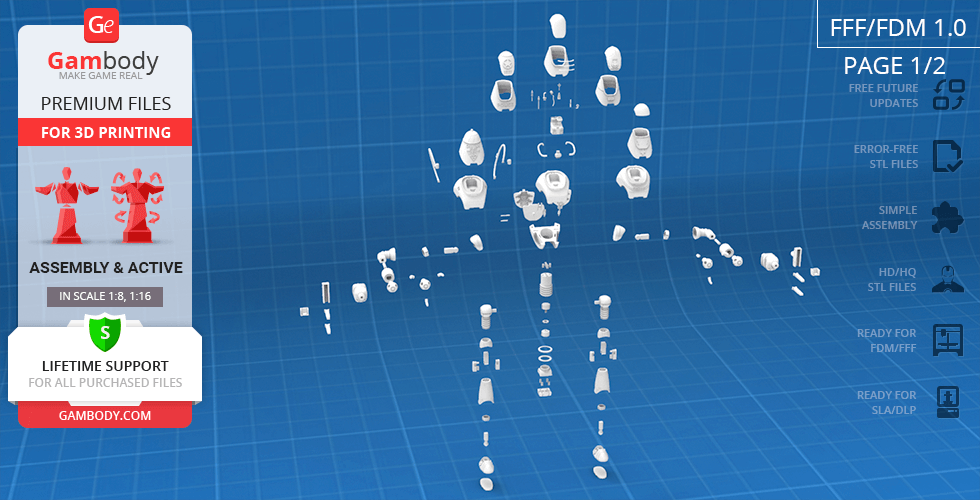
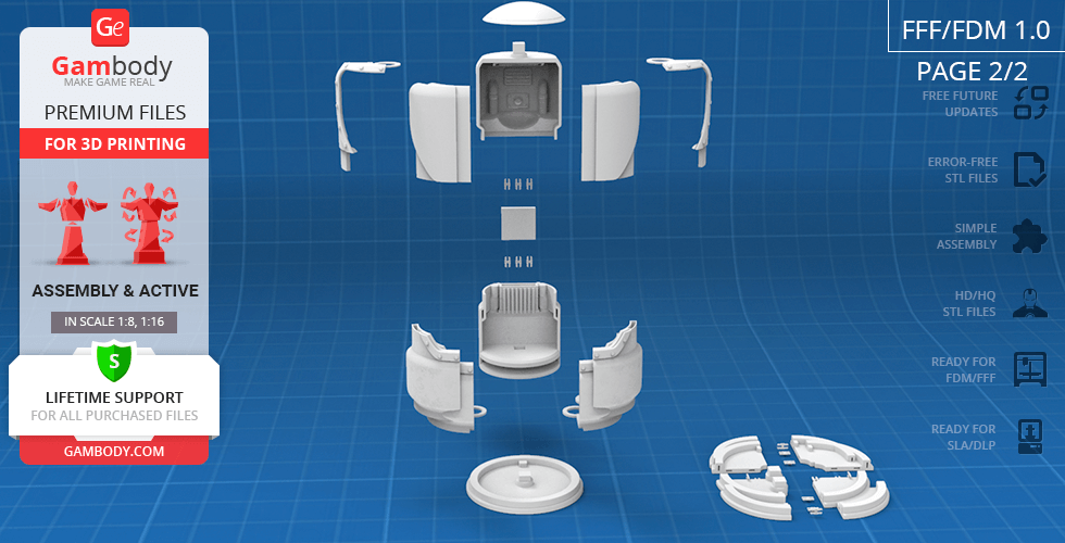
FFF/FDM
Assembly method
Connectors, Ge-Locks, Glue
Features
An updated version featuring enhanced joint stability and optimized files for large-scale printing; Includes an additional pin for the torso joint for increased structural integrity; All joints have been recalibrated and tested to maintain full functionality at larger scales; Features are the same as Version 1.0; The assembly parts are connected using specially designed integrated connectors that fit securely into the corresponding slots. Optionally, for added strength and rigidity, the static connections can be glued together. Some model parts use separate connectors (part "_100_Ge_lock_x22_10H_FDM", requires 22 copies).
FFF/FDM
Assembly method
Connectors, Ge-Locks, Glue
Features
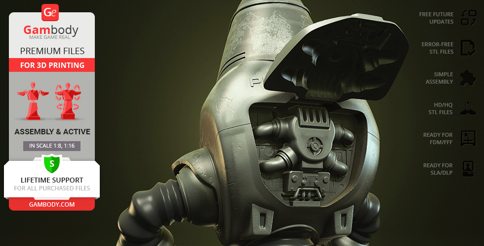
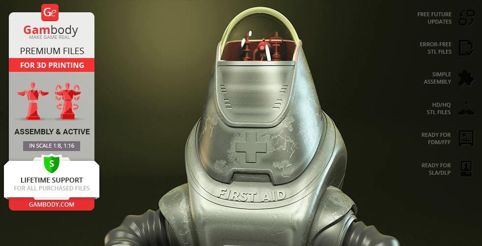
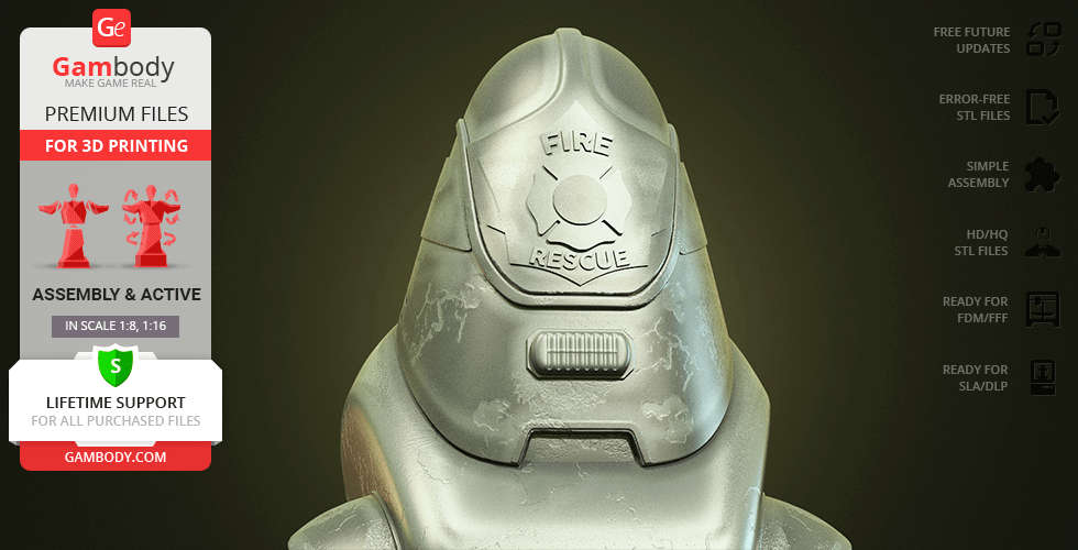
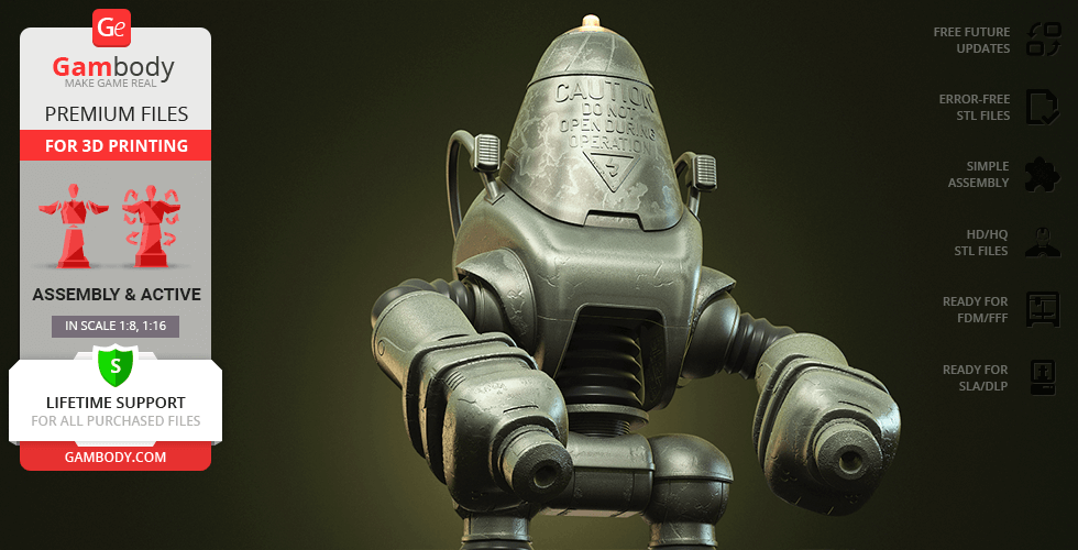
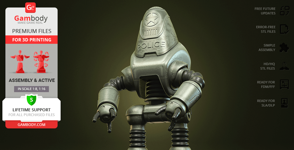
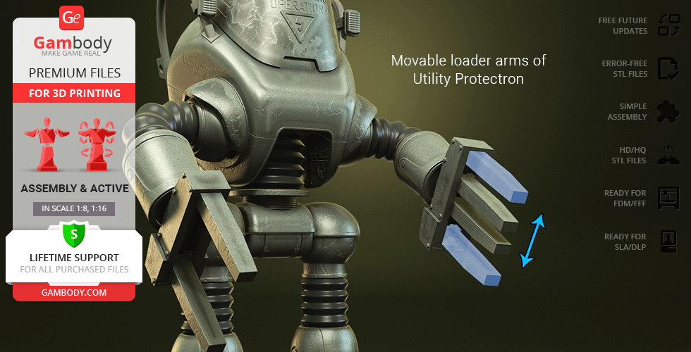
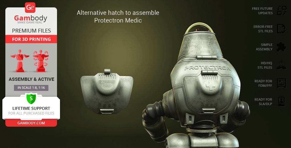
Includes 5 variants: Regular, Medic, Fire Brigadier, Utility, and Police; Features 5 hand types: regular, defibrillators, loader arms, and vacuum cleaners; Specialized bodies with floodlights or rear hatches; Highly articulated: adjustable ball-and-claw joints with tightening nuts in shoulders and hips; Ratchet mechanisms in knees and pelvis for stable posing; Opening dome and rear hatch with detailed CPU; LED-ready: internal tunnels for wiring and battery compartment; Includes Protectron Pod with sliding doors and separate glass for transparent filament; The assembly parts are connected using specially designed integrated connectors that fit securely into the corresponding slots. Optionally, for added strength and rigidity, the static connections can be glued together. Some model parts use separate connectors (part "100_Ge_lock_x22_10H_FDM", requires 22 copies).
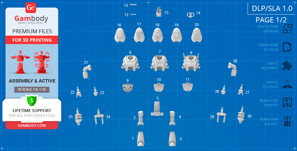
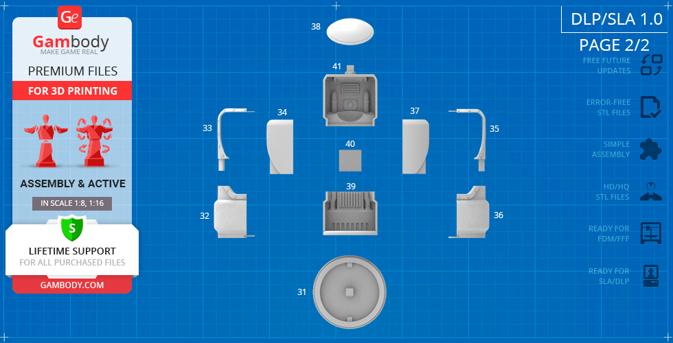
DLP/SLA
Eco parts
Assembly method
Connectors, Glue
Features
Includes 5 variants: Regular, Medic, Fire Brigadier, Utility, and Police; Features 5 hand types: regular, defibrillators, loader arms, and vacuum cleaners; Specialized bodies with floodlights or rear hatches; Articulated shoulders, wrists, pelvis, hips, and knees for dynamic posing; Opening dome and rear hatch with detailed CPU; Includes Protectron Pod with sliding doors and separate glass for transparent material; The assembly parts are connected using specially designed integrated connectors that fit securely into the corresponding slots. Optionally, for added strength and rigidity, the static connections can be glued together.
Additional details
Part of diorama
No
Special pack included
No
You will get instant access to the STL files of Protectron 3D Printing Model | Assembly + Action after completing your purchase. Simply add the model to your cart and check out using PayPal, credit or debit card, Apple Pay, Google Pay, Alipay, or other available payment methods.
Watch the assembly video for Protectron 3D Printing Model | Assembly + Action, and explore more tutorials, behind-the-scenes content, 3D printing timelapses, and painting guides on the official Gambody YouTube channel.
This 3D Model consists of files in StereoLithography (.Stl) format that is optimized for 3D printing.
Before printing the files, we strongly recommend reading the PRINTING DETAILS section.
Protectron 3D Printing Model comes in 2 versions for FFF/FDM and DLP/SLA/SLS 3D printers. STL files of both versions are available for download after the purchase.
Detailed information about this 3D printing model is available in the DESCRIPTION section.
Before printing, take a look at Printing Details for recommended settings and tips to achieve better results.
3D model history
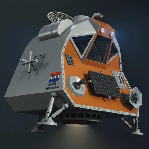
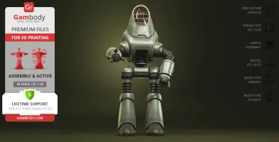
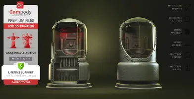
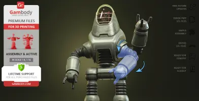
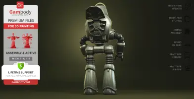
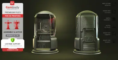
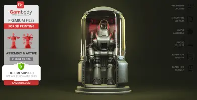
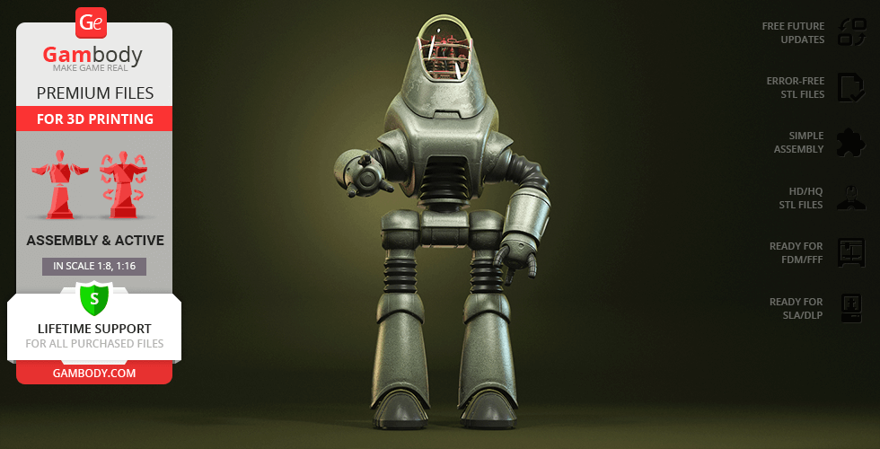
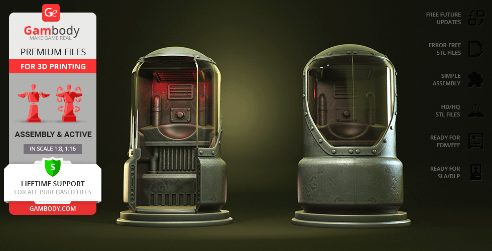
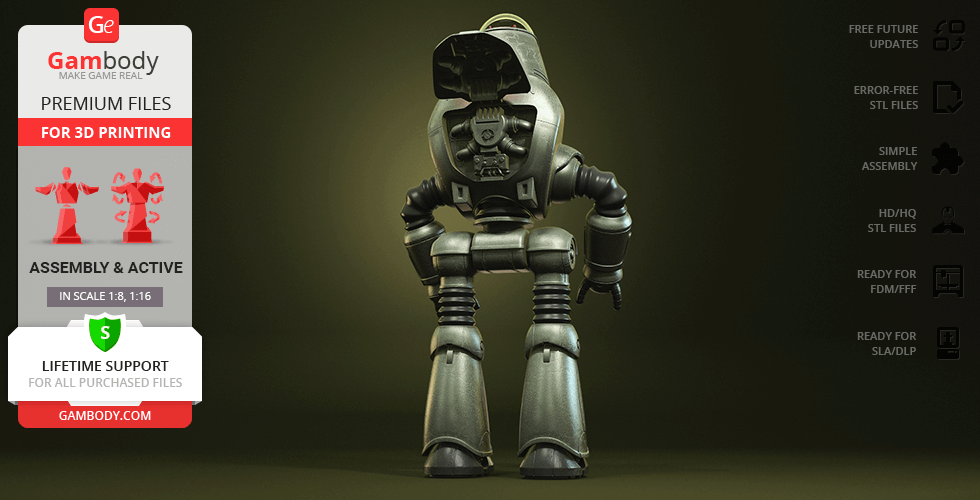
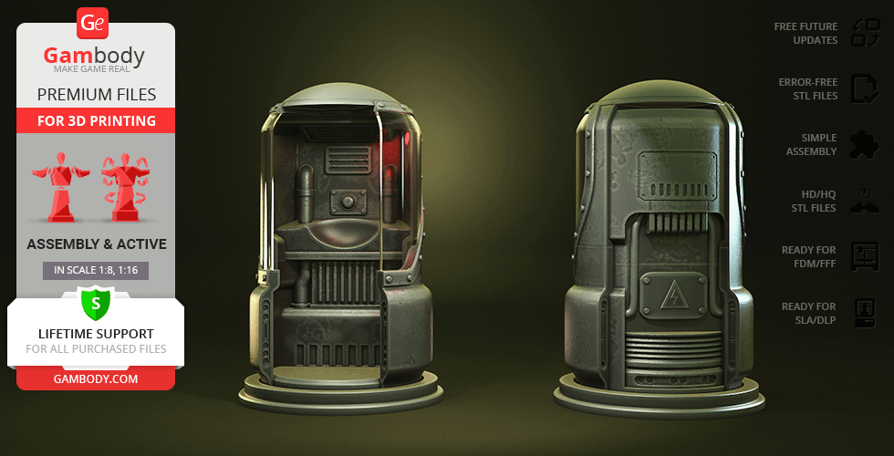
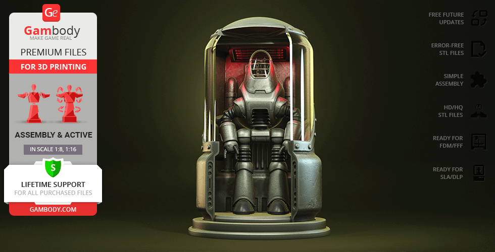
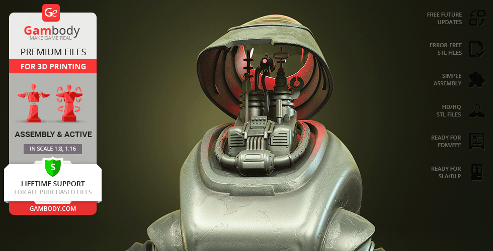
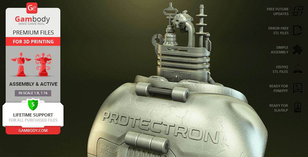
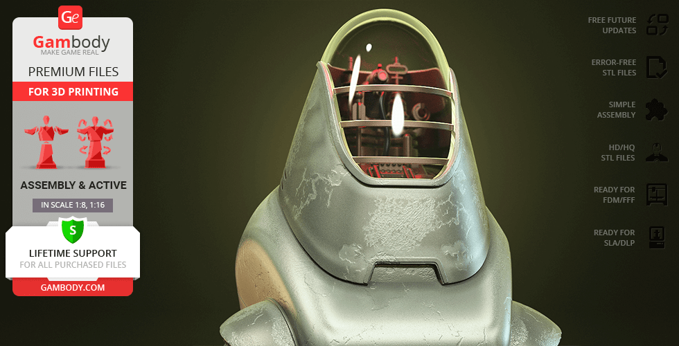
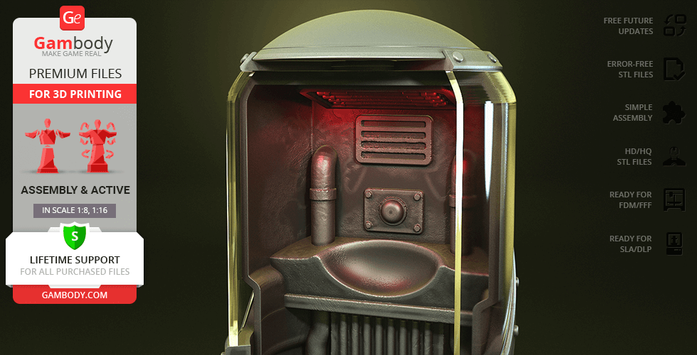
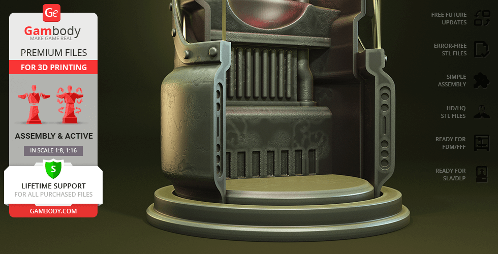
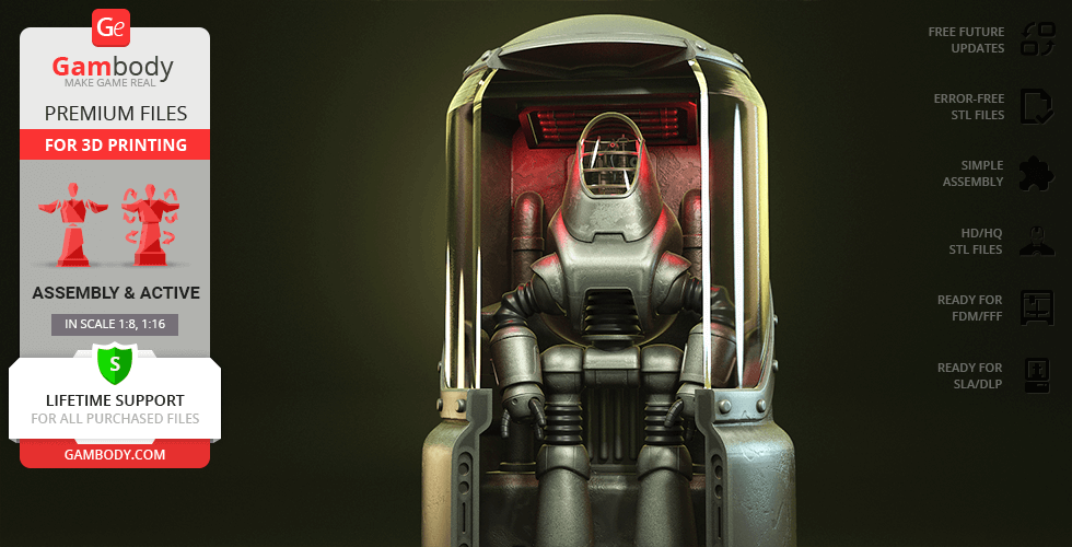
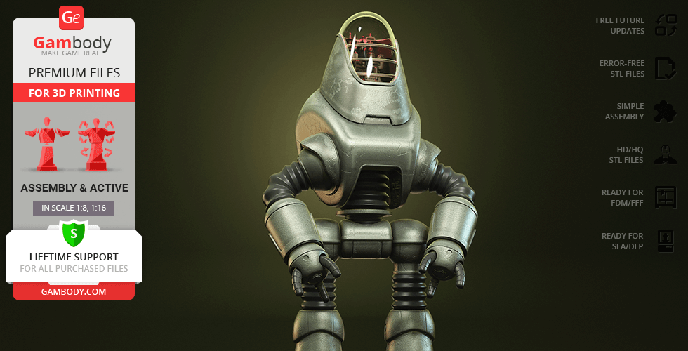
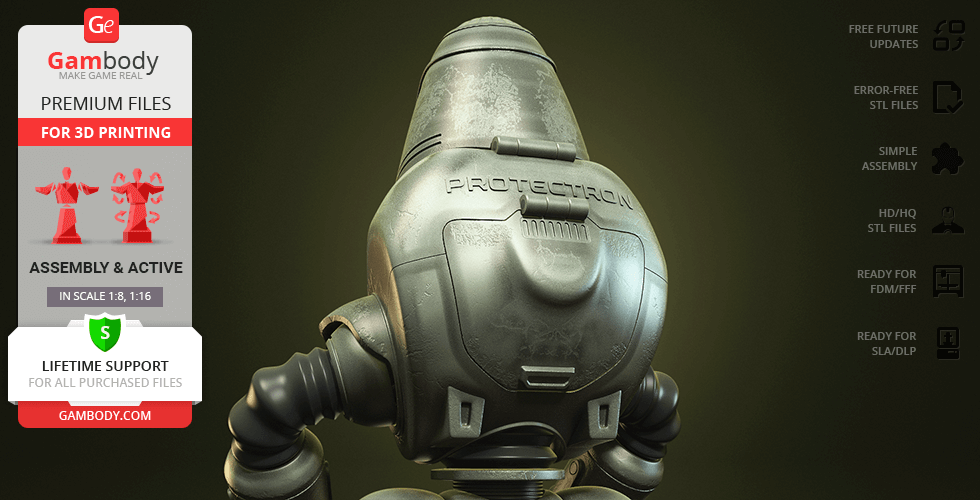
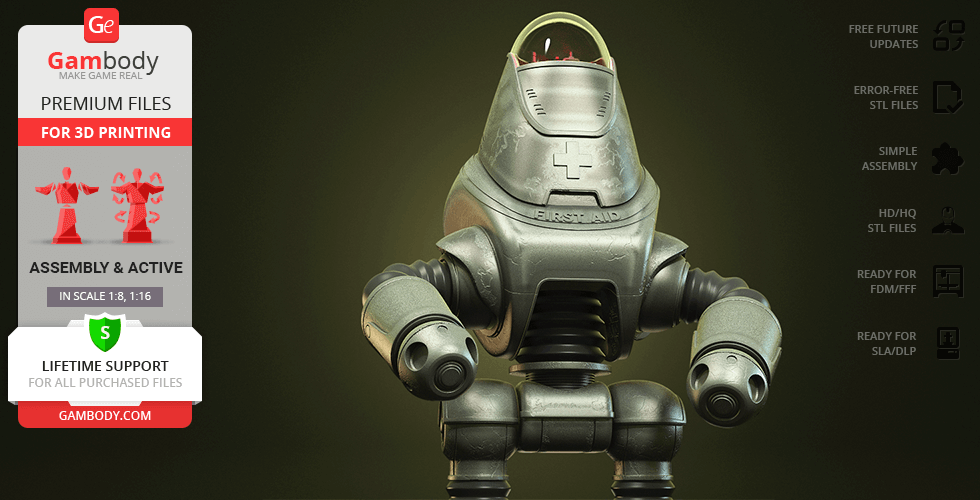
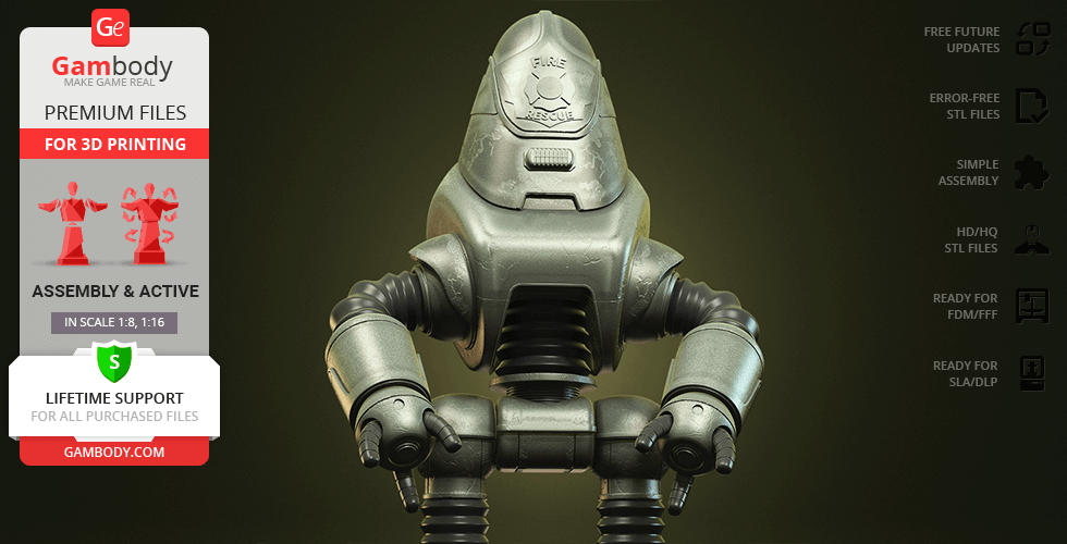
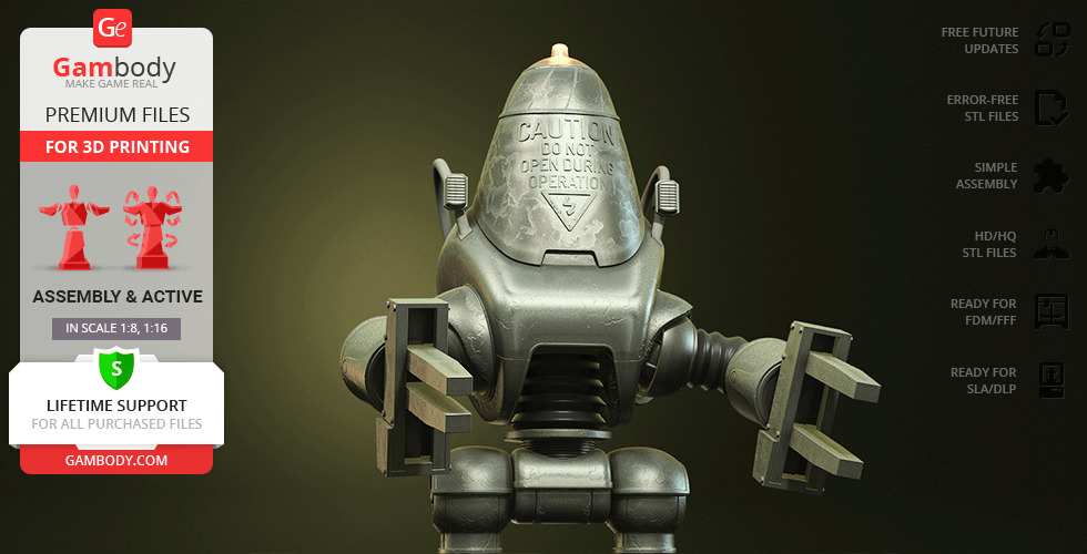
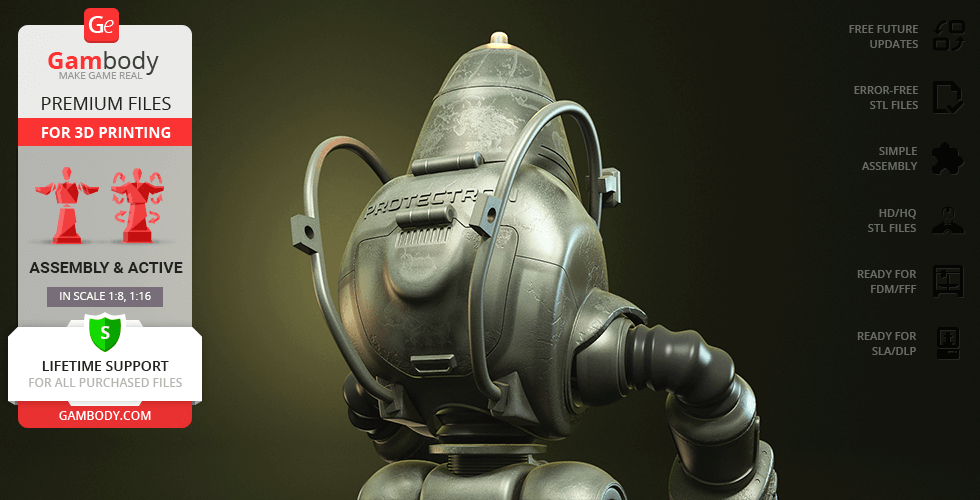
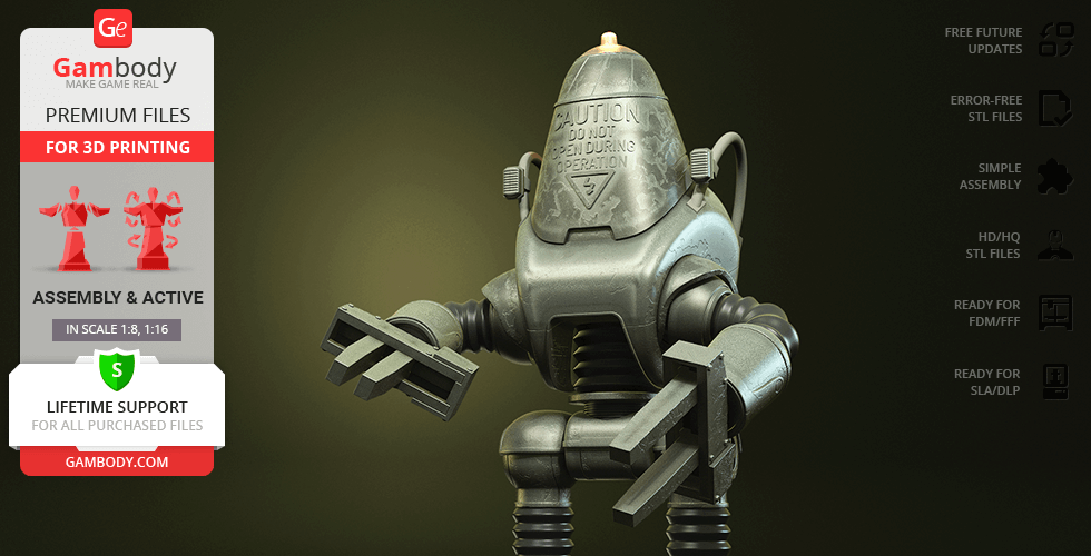
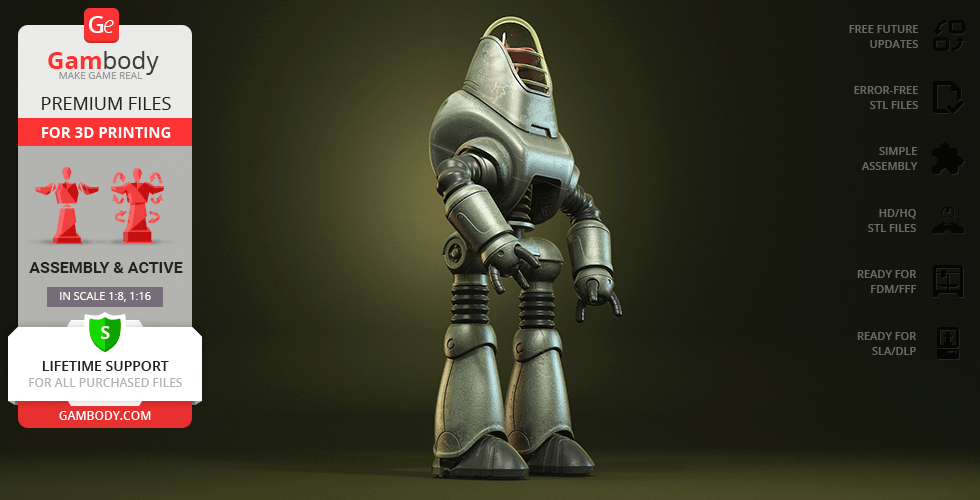
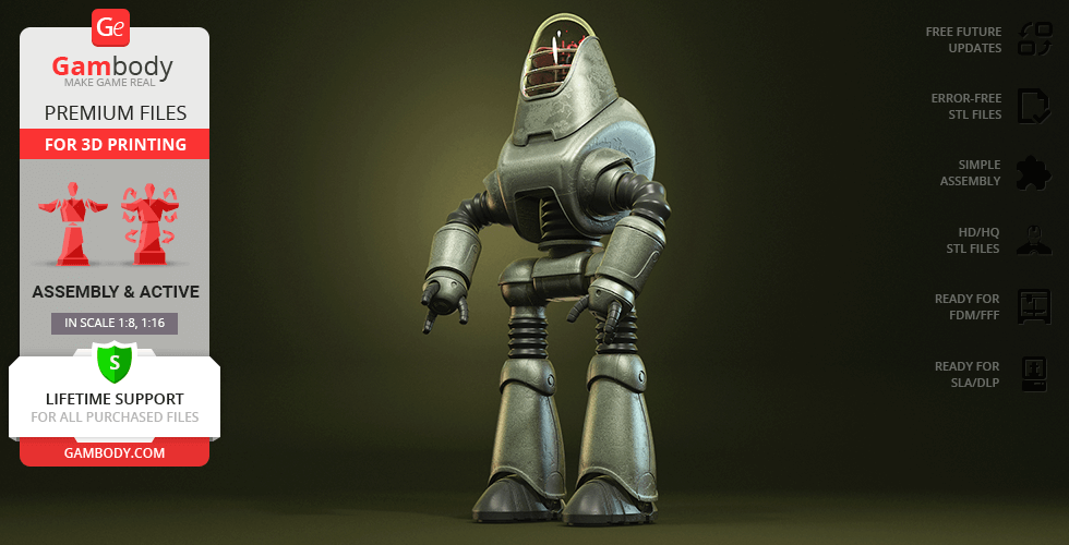
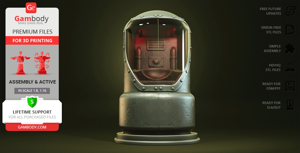
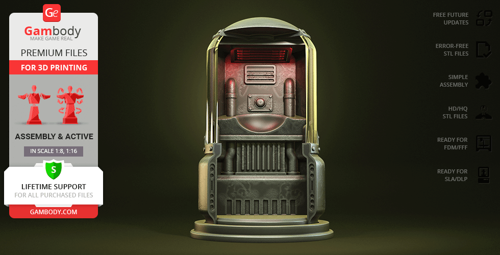
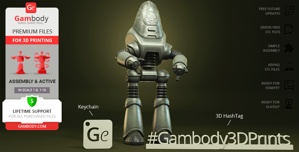
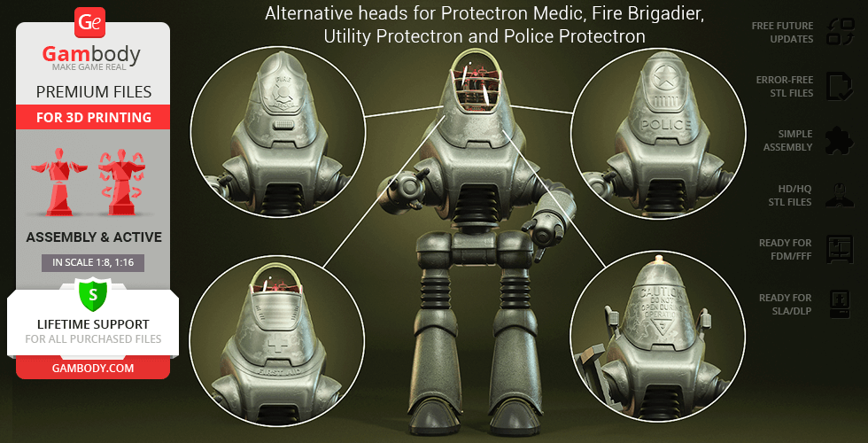
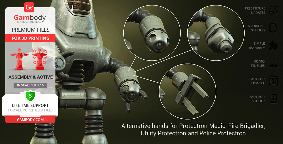
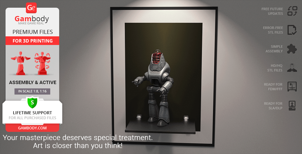
Protectron is a widespread type of work drone with a programmable personality that appears in a number of Fallout video game installments. Designed by a highly influential computer and robotics corporation in the pre-War United States, RobCo Industries, it was created to serve humans as an inexpensive and efficient labor machine. Inspired by the versatile robot encountered in the grim post-apocalyptic world of the game, our contributing 3D artist reportedly spent 193 hours to recreate the fan favourite Protectron for your 3D printing collection. The model pays tribute to the robot’s minimalistic exterior design notable for the smooth rounded shapes of the drone’s thin alloyed shell and dome-like head. The bipedal droid is equipped with a pair of manipulators that help it fulfill its mundane duties or act as a tool of self-defense. 3D printing Protectron’s body is intricately textured, capturing the weathered state of the machine that functions even after the world has collapsed. Just like RobCo Industries, our 3D modeler offers you various modifications of the droid to serve your needs: Regular Protectron, Fire Brigadier, Police Protectron, Protectron Medic, and Utility Protectron. The modes can be switched with the help of role-specific heads with corresponding logos engraved on the faceplate, as well as with the help of designated arm variants. In addition to all of the awesome variations, Protectron model also comes with its maintenance and charging chamber that is known as Protectron Pod. The chamber is going to be a perfect platform to store your chosen 3D printed Protectron personality!
3D printing model features
Model-specific features:
- This highly detailed Protectron 3D model is inspired by the versatile RobCo Industries work drone, capturing its minimalistic exterior and weathered, post-apocalyptic aesthetic.
- Includes parts to assemble five distinct variants: Regular Protectron, Medic, Fire Brigadier, Utility, and Police versions.
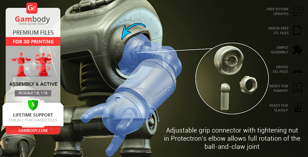
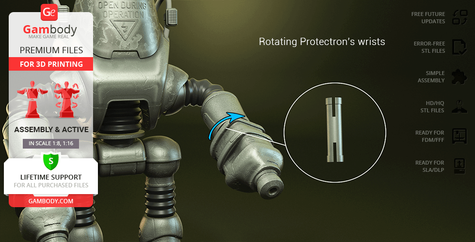
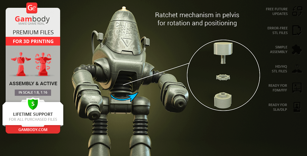
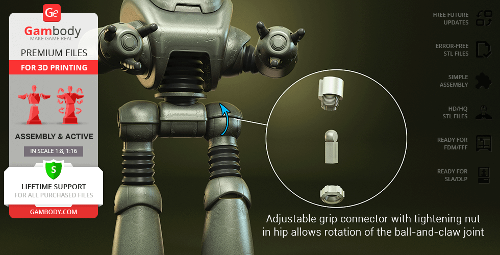
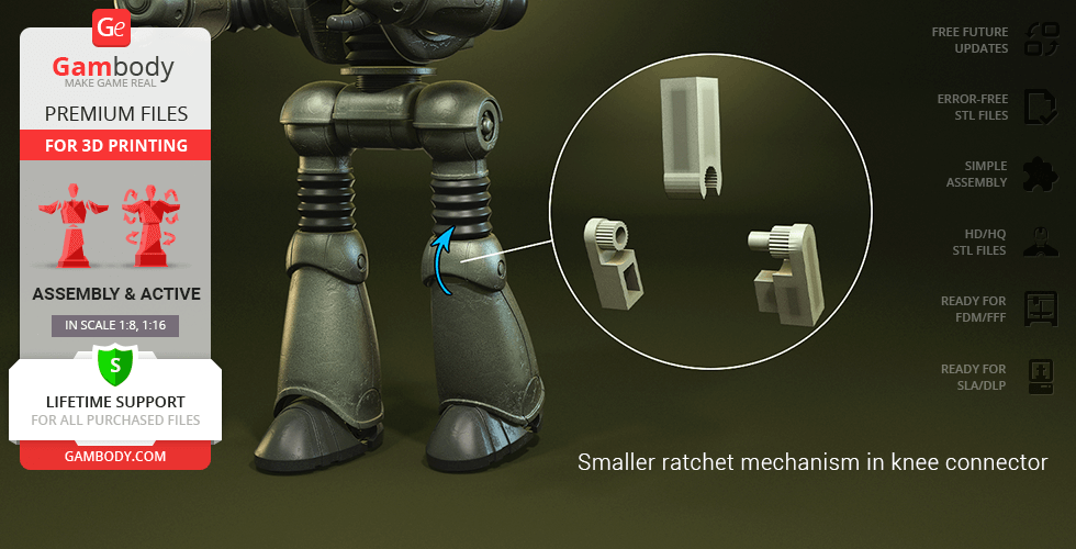
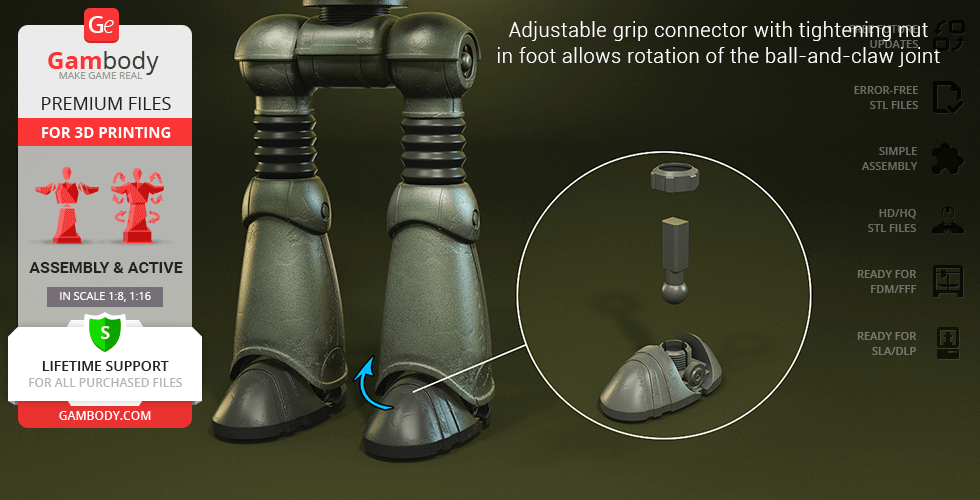
- Features multidirectional movement through ball-and-claw joints, ratchet mechanisms in the knees and pelvis, and articulated wrists.
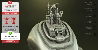
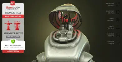
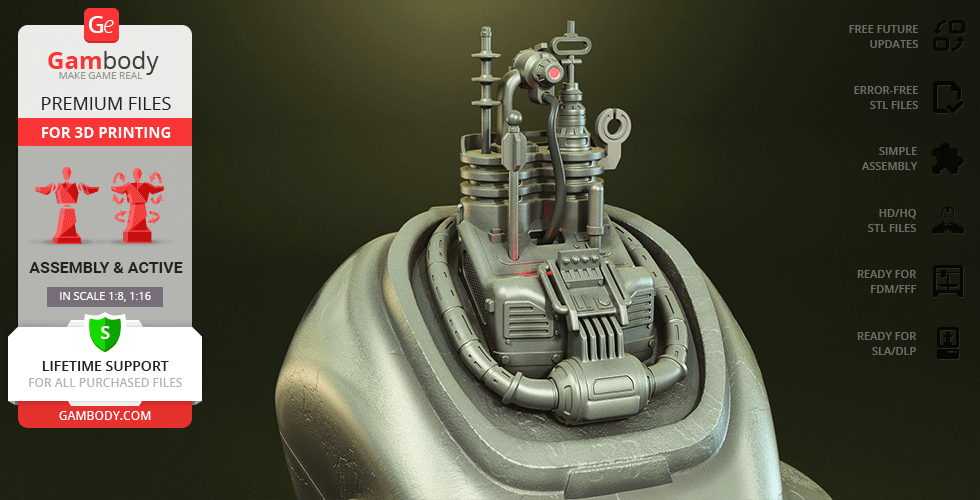
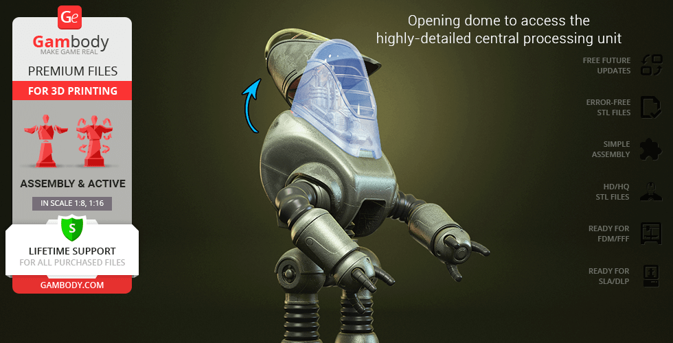
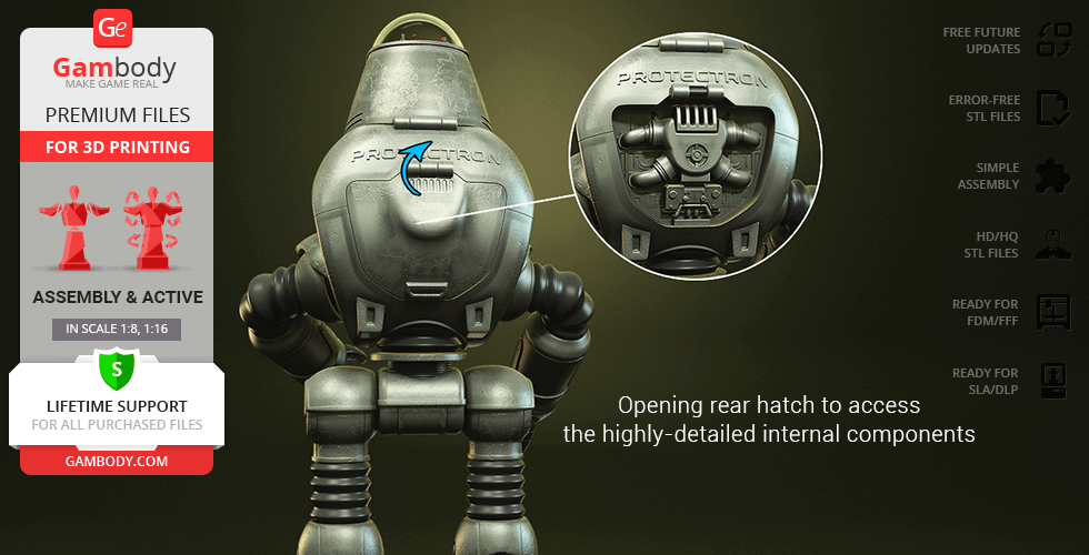
- Functional opening dome and rear hatch provide access to a highly detailed central processing unit and internal components.
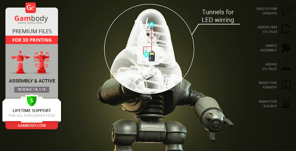
- Engineered with internal tunnels for wiring and a dedicated battery spot to light up the robot's head.
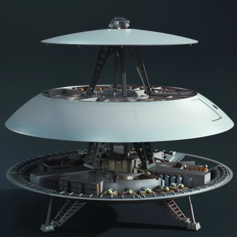
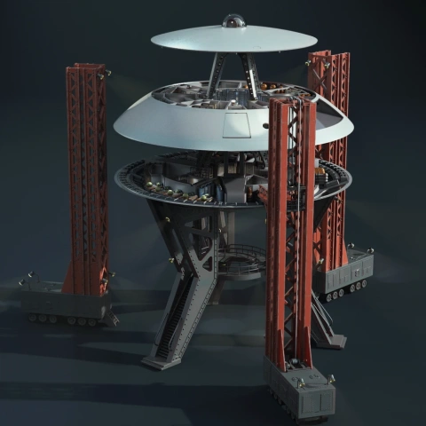
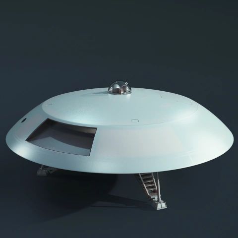
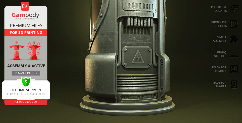
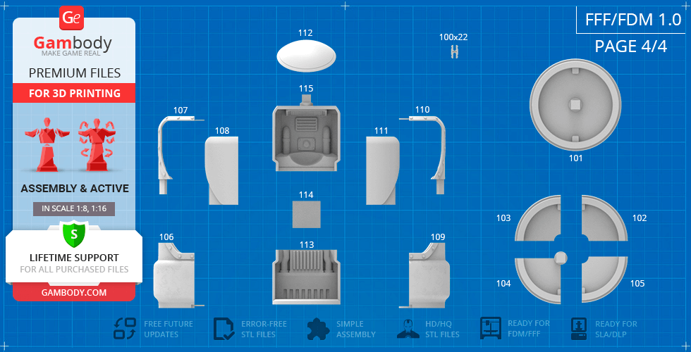
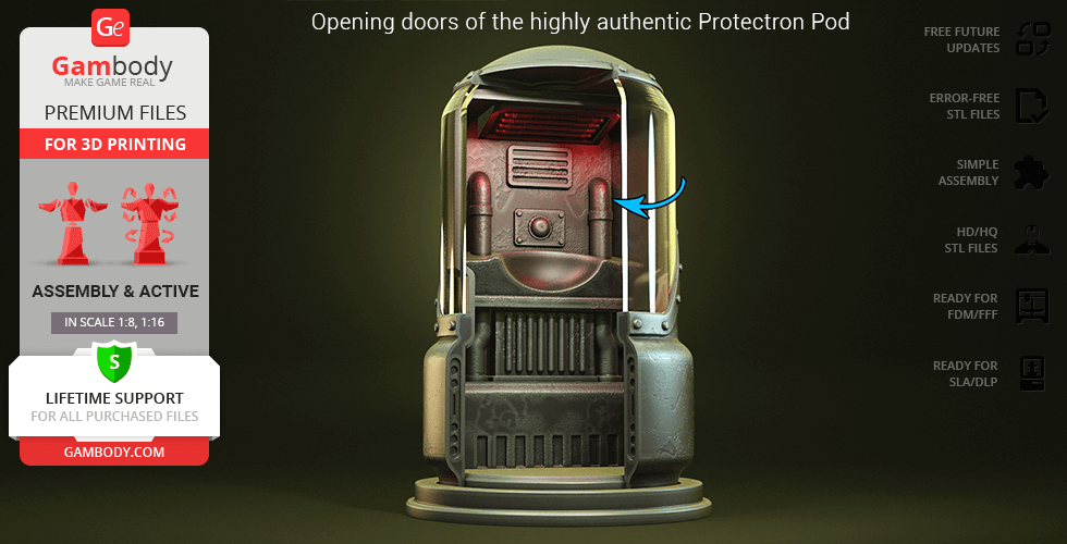
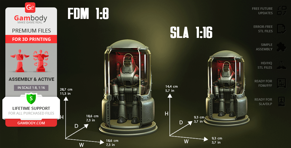
- The model comes with the Protectron Pod, which includes the authentic maintenance and charging chamber with sliding doors and separate glass parts for transparent printing.
Printing & assembly details:
- Provided as error-free STL files compatible with most 3D printers;
- Optimized part division minimizes support material and ensures smooth surface detail;
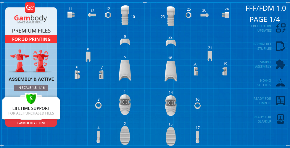
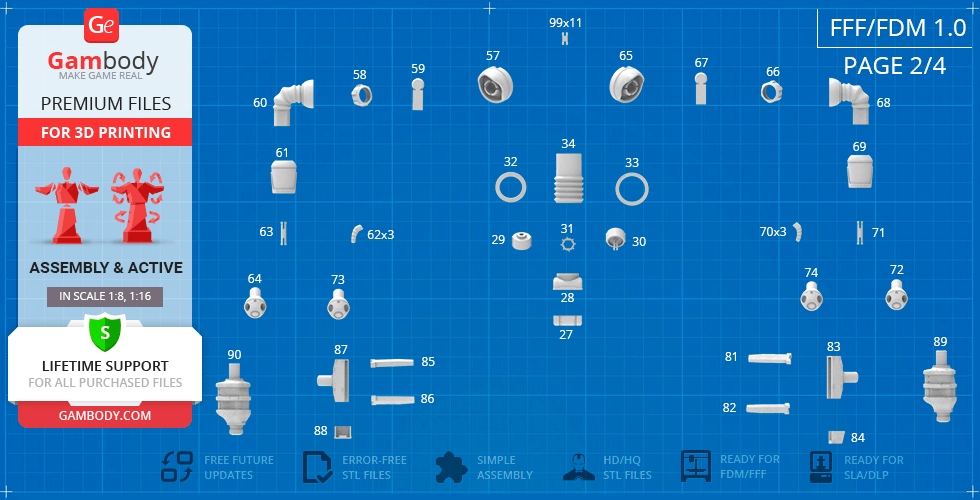
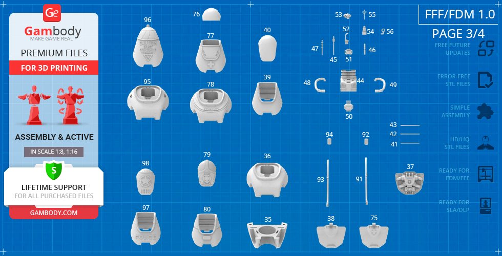
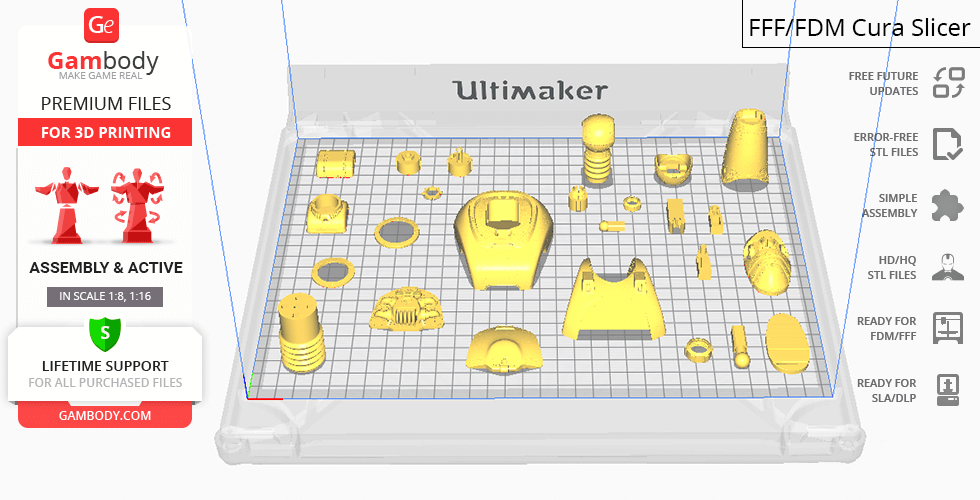
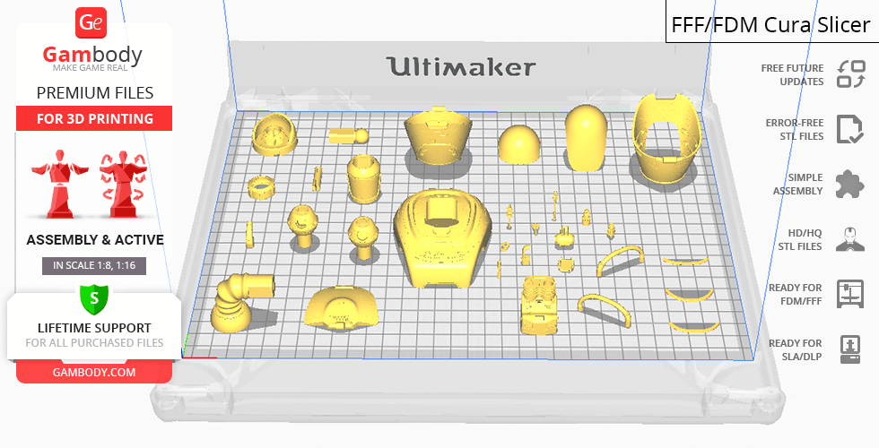
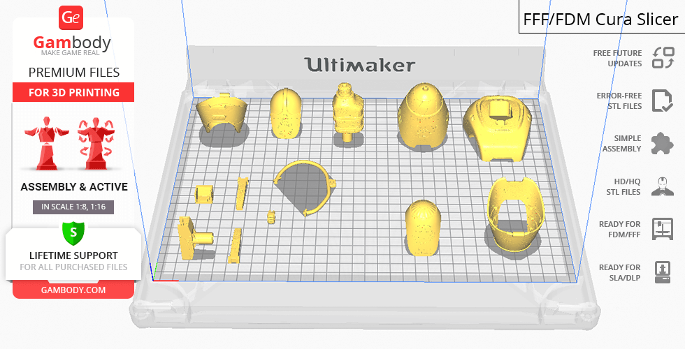
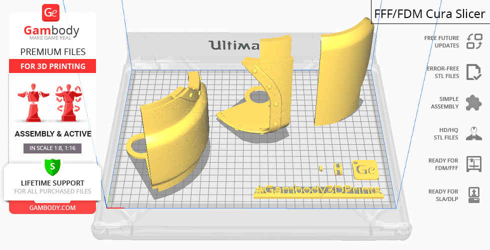
- The assembly parts in the FFF/FDM version come in the recommended print orientations for easy bed placement;
- Assembly manual in PDF and video formats is included for both FFF/FDM and DLP/SLA versions;
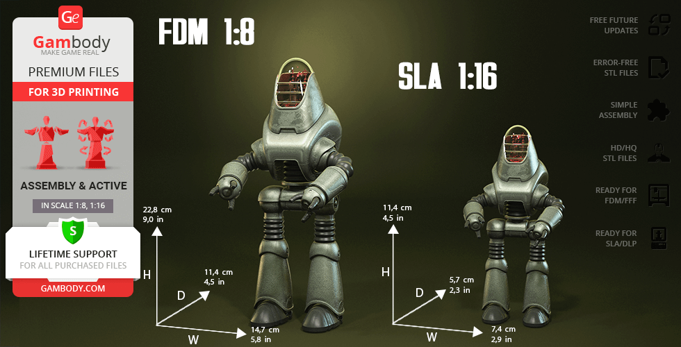
- The model is available in recommended scales of 1:8 for the FFF/FDM version and 1:16 for the DLP/SLA version.
What will you get after purchase?
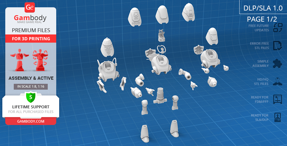
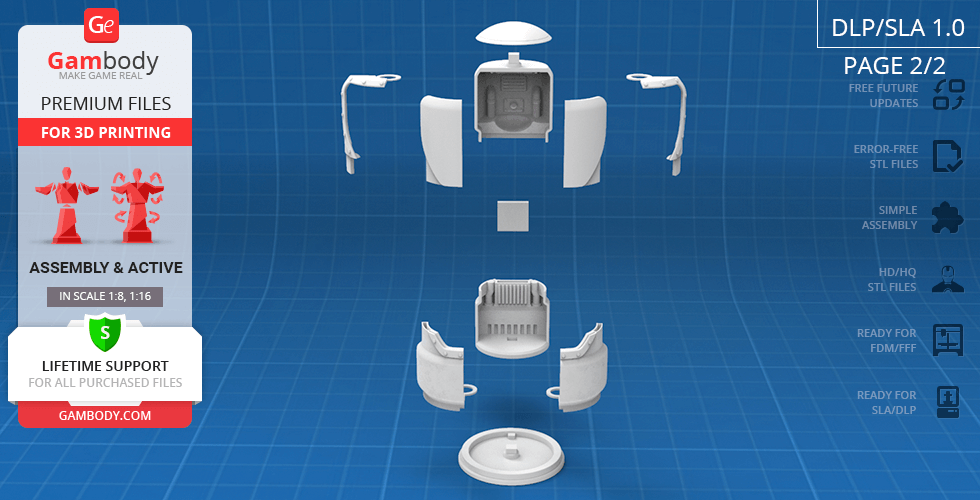
- 4 versions of ProtectronSTL files for FFF/FDM and DLP/SLA — files for all versions are available for download after the purchase;
- STL files of high-poly Protectron model for 3D printing consist of 272 files;
- Sizes for:
- FFF/FDM Model Size: 147 mm wide, 228 mm high, 114 mm deep;
- DLP/SLA Model Size: 74 mm wide, 114 mm high, 57 mm deep;
- Assembly Manual for 1.0 FFF/FDM and 1.0 DLP/SLA versions in PDF and video formats;
- Detailed settings that we provide as a recommendation for Bambu Studio, Cura, Orca Slicer, PrusaSlicer, Simplify3D, and Slic3r for the best print;
- Full technical support from the Gambody Support Team.
Average customer rating (5 reviews)
4.8
Ratings breakdown
Click a star rating to filter reviews
Overall experience
Level of detail in the model
4.8
Model cut quality and assembly guide
4.8
Clarity and accuracy of the model page
4.8
Level of detail in the model
4
Model cut quality and assembly guide
4
Clarity and accuracy of the model page
4
Level of detail in the model
5
Model cut quality and assembly guide
5
Clarity and accuracy of the model page
5
Level of detail in the model
5
Model cut quality and assembly guide
5
Clarity and accuracy of the model page
5
Level of detail in the model
5
Model cut quality and assembly guide
5
Clarity and accuracy of the model page
5
Level of detail in the model
5
Model cut quality and assembly guide
5
Clarity and accuracy of the model page
5
Below you'll find detailed slicing settings for Bambu Studio 2.0+, Orca Slicer 2.0+, UltiMaker Cura 5.0+, PrusaSlicer 2.0+, Slic3r 1.3+, Simplify3D 5.0+ to help you get the best results when printing this model. These settings are optimized specifically for this 3D model, but please note they may need slight adjustments depending on your printer or filament. When in doubt, refer to your printer's user manual.
To avoid printing issues and achieve the best quality, we highly recommend applying the following settings:
For better quality use 0.12 mm layer height, for fast printing use 0.2 mm layer height. For pins and the Ge connectors, use 0.2 layer height.
120-150% of your Layer Height
But you can paint the seam if you want.
You have to calibrate this parameter
You have to calibrate this parameter
You have to calibrate this parameter
For pins and power elements of the structure, such as the vehicle frame, use 3 loop
Disabled for vehicles and enabled for characters
For 0,2 Layer Height
The parameters in this tab vary greatly, it all depends on the quality of your printer. For example, if you have a classic Ender3, stick to the minimum parameters, but if you have a newer printer, for example Anycubic cobra 3 v2, you can select the maximum recommended values
Settings for advanced users, change these parameters only if you have sufficient 3D printing expertise
Enable this parameter if your model requires supports
We also recommend placing and removing supports manually in some places using special button
1-2 loops for more thick support
Top Z distance = 1-1.3 layer Height. If the supports are hard to remove, try increasing this setting by 0.1-0,4 mm
Bottom Z distance = 1-1.3 layer Height. If the supports are hard to remove, try increasing this setting by 0.1-0,4 mm
You have to calibrate this parameter which one is better for your filament
Increase this parameter if the supports are hard to remove from walls
For PLA and PETG filament types
5-8 mm is optional for small prints that have bad adhesion to the build plate
You have to calibrate this parameter
Read the description on your filament roll
Read the description on your filament roll and increase this parameter for fast printers
Read the description on your filament roll and increase this parameter for fast printers
For better quality use 0.12 mm layer height, for fast printing use 0.2 mm layer height. For pins and the Ge connectors, use 0.2 layer height.
120-150% of your Layer Height
But you can paint the seam if you want.
0.01-0.05 You have to calibrate this parameter
0.01-0.05 You have to calibrate this parameter
0.1-0.2 You have to calibrate this parameter
For pins and power elements of the structure, such as the vehicle frame, use 3 loop
Disabled for vehicles and ships, enabled for characters
For 0,2 Layer Height
For 0,2 Layer Height
The parameters in this tab vary greatly, it all depends on the quality of your printer. For example, if you have a classic Ender3, stick to the minimum parameters, but if you have a newer printer, for example, Anycubic Kobra 3 Or Bambulab A1, you can select the maximum recommended values.
Settings for advanced users, change these parameters only if you have sufficient 3D printing expertise
Enable this parameter if your model requires supports
We also recommend placing and removing supports manually in some places using special button
Top Z distance = 1-1.3 layer Height. If the supports are hard to remove, try increasing this setting by 0.1-0,4 mm
Bottom Z distance = 1-1.3 layer Height. If the supports are hard to remove, try increasing this setting by 0.1-0,4 mm
Increase this parameter if the supports are hard to remove from walls
For PLA and PETG filament types
5-8 mm is optional for small prints that have bad adhesion to the build plate
Read the description on your filament roll
Read the description on your filament roll and increase this parameter for fast printers
You have to calibrate this parameter
Read the description on your filament roll and increase this parameter for fast printers
Read the description on your filament roll
This field is filled in according to your printer specifications when you add it to the slicer.
You can add custom G-code here for the start and end of the print. However, be careful - this is for advanced users only!
You have to calibrate your printer using Ge retraction test models
Retraction Length: For direct-drive setups use 0.5 mm to 2.5 mm; for Bowden extruders use 5 to 7 mm
This is how fast the filament is pulled back—40-60 mm/s for direct drive and 30-50 mm/s for Bowden setups.
You have to calibrate this parameter: Reduce it until the printer starts to hit the parts with the nozzle during printing, then increase it by 0.2.
For better quality use 0.12 mm layer height, for fast printing use 0.2 mm layer height. For pins and the Ge connectors, use 0.2 layer height.
120-150% of your Layer Height
To increase the strength of the print parts, use wall line count: 3
For pins and connectors use 50% Infill
These parameters are for standard PLA plastic. If you are using a different type of plastic, check the printing temperature recommended by the manufacturer. Also, read the description on your filament spool. For fast printers, add +30 °C to the current parameters.
The parameters in this tab vary greatly, it all depends on the quality of your printer. For example, if you have a classic Ender3, stick to the minimum parameters, but if you have a newer printer, for example Anycubic cobra 3 v3, you can select the maximum recommended values
Settings for advanced users, change these parameters only if you have sufficient 3D printing expertise.
You need to calibrate this parameter using Gambody test models. These values are average values for a Direct Drive extruder; for a Bowden extruder, the values should be increased.
You need to calibrate this parameter using Gambody test models. These values are average values for a Direct Drive extruder; for a Bowden extruder, the values should be increased.
Use this value other than 0 if your nozzle catches on the internal infill during travel moves. Try to keep this value as low as possible in height.
Use normal supports to support large, straight surfaces (most mechanical or technical parts).
You have to calibrate this parameter according to the capabilities of your printer and your filament, using a Gambody test models.
Use 1 instead of 0 if your supports are thin and tall. They will be harder to remove, but much stronger.
Top Z distance = 1-1.3 layer Height. If the supports are hard to remove, try increasing this setting by 0.1-0,4 mm
Increase this parameter if the supports are hard to remove from walls
Use tree supports to support complex objects, such as characters.
You have to calibrate this parameter according to the capabilities of your printer and your filament, using a Gambody test models.
Top Z distance = 1-1.3 layer Height. If the supports are hard to remove, try increasing this setting by 0.1-0,4 mm
Increase this parameter if the supports are hard to remove from walls
Use a skirt for all parts when printing on outdated printers.
Use a brim when printing thin but tall parts, as well as parts with a small bed adhesion area.
For better quality use 0.12 mm layer height, for fast printing use 0.2 mm layer height. For pins and the Ge connectors, use 0.2 layer height.
120-150% of your Layer Height
for 0.2 Layer Height
But you can paint the seam if you want.
(for PLA and PETG)
(5-8 mm is optional for small prints that have bad adhesion to the build plate)
Enable this parameter if your model requires supports
(45-50 degree)You have to calibrate this parameter according to the capabilities of your printer
and your filament, using a Gambody test models.
Top contact Z distance = 1-1.3 layer Height. If the supports are hard to remove, try
increasing this setting by 0.1-0,4 mm
Top contact Z distance = 1-1.3 layer Height. If the supports are hard to remove, try
increasing this setting by 0.1-0,4 mm
Increase this parameter if the supports are hard to remove from walls
The parameters in this tab vary greatly, it all depends on the quality of your printer. For example, if you have a classic Ender3, stick to the minimum parameters, but if you have a newer printer, for example Anycubic cobra 3 v3, you can select the maximum recommended values
Settings for advanced users, change these parameters only if you have sufficient 3D printing expertise. Use the minimum value for outdated printers without acceleration calibration, and the maximum value for modern printers if you need it.
These settings only work for 3D printers with multiple extruders
You can try setting all parameters in this section, except the First layer, to values between 0.75% of your nozzle diameter and 1.25% of your nozzle diameter. Adjusting them will help you work out the optimal parameters for the best quality for your print. As for the First layer, you can set it to 150% of the diameter of your nozzle for better adhesion to the build plate (for a nozzle with a diameter of 0.4 mm, the First layer extrusion width can be from 0.3 mm to 0.5 mm)
For better printing quality you have to calibrate this parameter using Gambody test model.
Check your filament manufacturer's temperature recommendations on the spool.
Cooling parameters depends on the material you use for printing.
*for PLA
For better quality use 0.12 mm layer height, for fast printing use 0.2 mm layer height. For pins and the Ge connectors, use 0.2 layer height.
120-150% of your Layer Height
For 0.12 Layer Height
For 0.12 Layer Height
For pins and connectors use 50% Infill
Use skirt for outdated 3d printers
(5-8 mm is optional for small prints that have bad adhesion to the build plate)
Enable this parameter if your model requires supports
(45-60 degree)You have to calibrate this parameter according to the capabilities of your printer and your filament, using a Gambody test models
Contact Z distance = 1-1.3 layer Height. If the supports are hard to remove, try increasing this setting by 0.1-0,4 mm
The parameters in this tab vary greatly, it all depends on the quality of your printer. For example, if you have a classic Ender3, stick to the minimum parameters, but if you have a newer printer, for example Anycubic cobra 3 v3, you can select the maximum recommended values
Settings for advanced users, change these parameters only if you have sufficient 3D printing expertise. Use the minimum value for outdated printers without acceleration calibration, and the maximum value for modern printers if you need it.
You have to calibrate this parameter from 0.9 to 1.1 according to the capabilities of your printer and your filament, using a Gambody test models.
Check your filament manufacturer's temperature recommendations on the spool.
Cooling parameters depends on the material you use for printing.
Calibrate this value if you need to reduce or improve the adhesion between the plastic and the heat bed
Your current nozzle diameter
You need to calibrate this parameter using Gambody test models. These values are average values for a Direct Drive extruder; for a Bowden extruder, the values should be increased.
Your current nozzle diameter
You have to calibrate this parameter using Gambody test models.
You need to calibrate this parameter using Gambody test models. These values are average values for a Direct Drive extruder; for a Bowden extruder, the values should be increased.
For better quality use 0.12 mm layer height, for fast printing use 0.2 mm layer height. For pins and the Ge connectors, use 0.2 layer height.
For 0,2 Layer Height
For 0,2 Layer Height
To increase the strength of the print parts, use Outline Perimeters: 3
You can enable this parameter to print rounded or spherical models, as well as character models.
Use this option only if your parts are too tight. but better calibrate your printer extrusion
Use this option only if your parts are too tight. but better calibrate your printer extrusion
Use 2 and more if you want to create skirt instead brim
1-2 for skirt and 10-20 for brim
Use for wipe nozzle if you need
Use For ABS filament
For pins and connectors use 50% Infill
Top Z distance = 1-1.3 layer Height. If the supports are hard to remove, try increasing this setting by 0.1-0,4 mm
Calibrate your filament and detect optimal temperature for it
Average temperature for PLA filament
The parameters in this tab vary greatly, it all depends on the quality of your printer. For example, if you have a classic Ender3, stick to the minimum parameters, but if you have a newer printer, for example Anycubic cobra 3 v3, you can select the maximum recommended values
Settings for advanced users, change these parameters only if you have sufficient 3D printing expertise.
FFF/FDM
An updated version featuring enhanced joint stability and optimized files for large-scale printing; Includes an additional pin for the torso joint for increased structural integrity; All joints have been recalibrated and tested to maintain full functionality at larger scales; Features are the same as Version 1.0; The assembly parts are connected using specially designed integrated connectors that fit securely into the corresponding slots. Optionally, for added strength and rigidity, the static connections can be glued together. Some model parts use separate connectors (part "_100_Ge_lock_x22_10H_FDM", requires 22 copies).
DLP/SLA
Includes 5 variants: Regular, Medic, Fire Brigadier, Utility, and Police; Features 5 hand types: regular, defibrillators, loader arms, and vacuum cleaners; Specialized bodies with floodlights or rear hatches; Articulated shoulders, wrists, pelvis, hips, and knees for dynamic posing; Opening dome and rear hatch with detailed CPU; Includes Protectron Pod with sliding doors and separate glass for transparent material; The assembly parts are connected using specially designed integrated connectors that fit securely into the corresponding slots. Optionally, for added strength and rigidity, the static connections can be glued together.
FFF/FDM
Includes 5 variants: Regular, Medic, Fire Brigadier, Utility, and Police; Features 5 hand types: regular, defibrillators, loader arms, and vacuum cleaners; Specialized bodies with floodlights or rear hatches; Highly articulated: adjustable ball-and-claw joints with tightening nuts in shoulders and hips; Ratchet mechanisms in knees and pelvis for stable posing; Opening dome and rear hatch with detailed CPU; LED-ready: internal tunnels for wiring and battery compartment; Includes Protectron Pod with sliding doors and separate glass for transparent filament; The assembly parts are connected using specially designed integrated connectors that fit securely into the corresponding slots. Optionally, for added strength and rigidity, the static connections can be glued together. Some model parts use separate connectors (part "100_Ge_lock_x22_10H_FDM", requires 22 copies).