


Files
3D model format
Stereolithography (.stl)
Total files
Slicer settings
Mesh error check
Netfabb
Support
Lifetime support from Gambody team
Update requests
Available to verified buyers
Model complexity
Standard: balanced printing difficulty and moderate part count with assembly steps.
Advanced: may require tuning print settings or support placement, plus precise fitting, gluing, or sanding.
Model versions
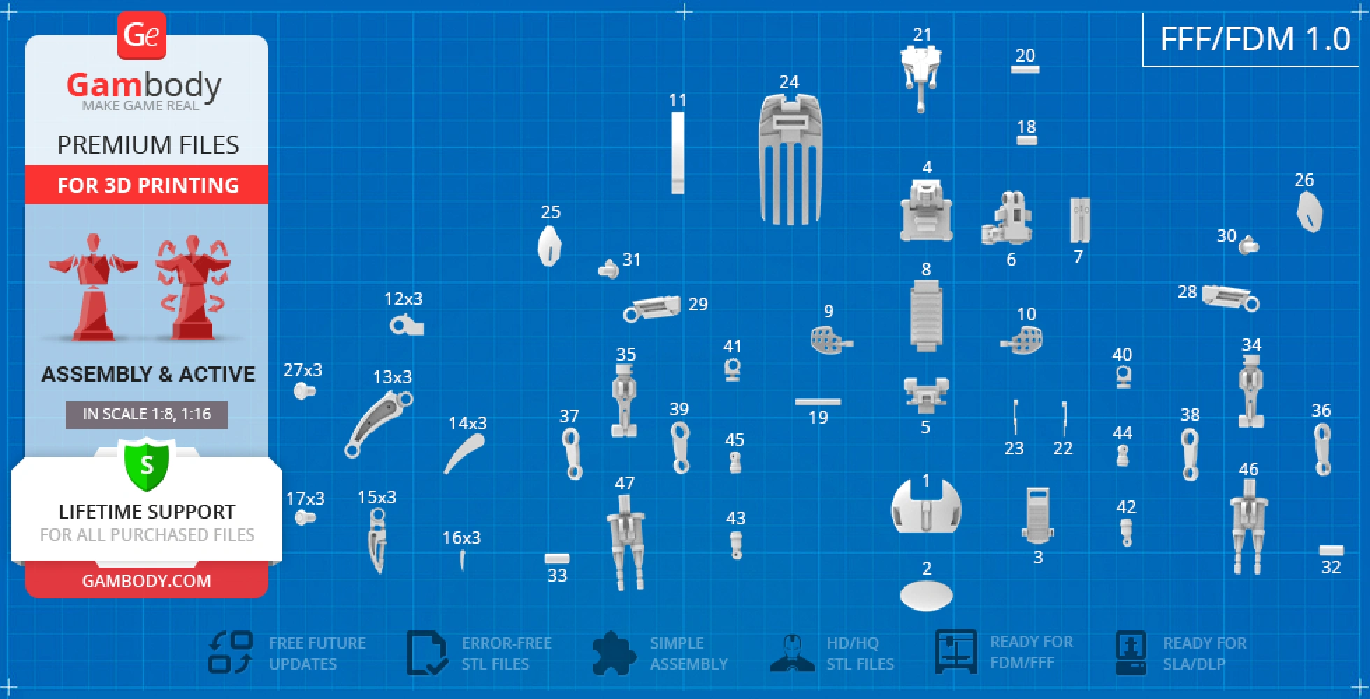
FFF/FDM
Assembly method
not specified
Features
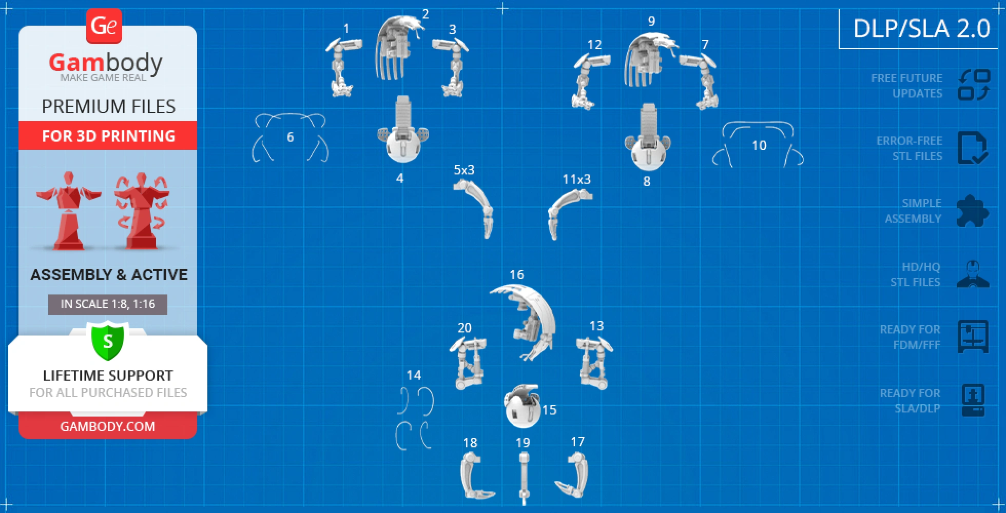
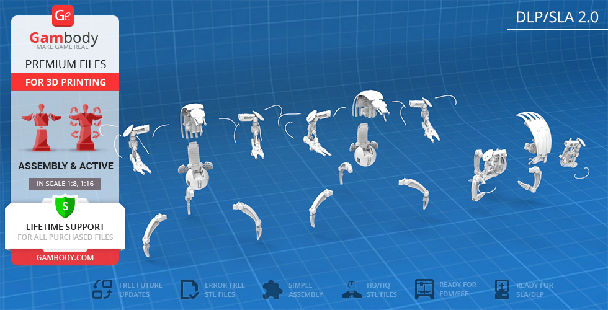
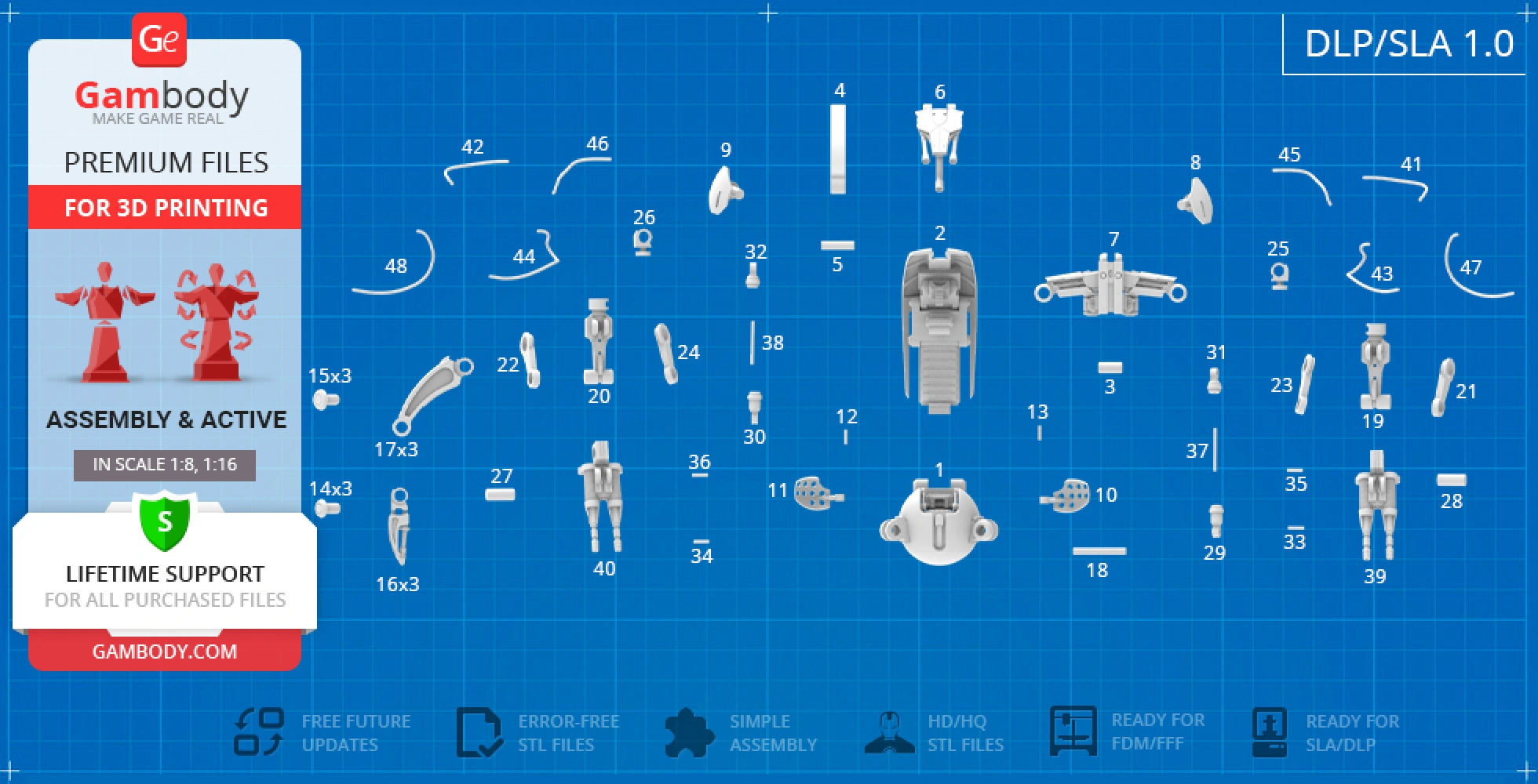
DLP/SLA
Assembly method
not specified
Features
FFF/FDM
Assembly method
not specified
Features
DLP/SLA
Assembly method
not specified
Features
Additional details
Part of diorama
No
Special pack included
No
You will get instant access to the STL files of Droideka 3D Printing Model | Assembly + Action after completing your purchase. Simply add the model to your cart and check out using PayPal, credit or debit card, Apple Pay, Google Pay, Alipay, or other available payment methods.
Watch the assembly video for Droideka 3D Printing Model | Assembly + Action, and explore more tutorials, behind-the-scenes content, 3D printing timelapses, and painting guides on the official Gambody YouTube channel.
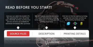
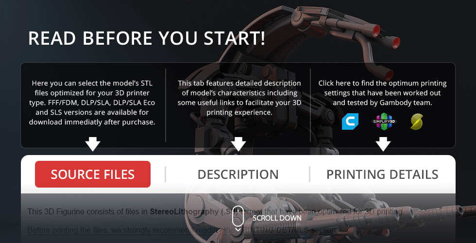
This 3D Model consists of files in StereoLithography (.Stl) format that is optimized for 3D printing.
Before printing the files, we strongly recommend reading the PRINTING DETAILS section.
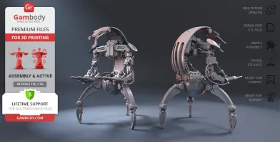
Droideka 3D Printing Model comes in 2 versions for FFF/FDM and DLP/SLA/SLS 3D printers. Files for both versions are available for download after purchase.
Detailed information about this 3D printing model is available in the DESCRIPTION section.
Before printing, take a look at Printing Details for recommended settings and tips to achieve better results.
ABOUT THIS 3D MODEL
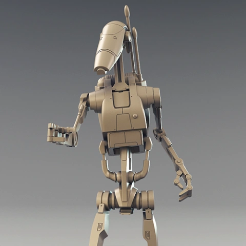
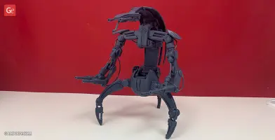
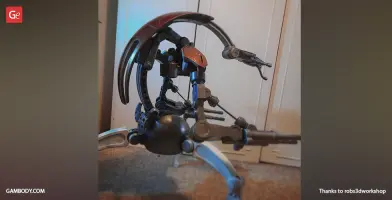
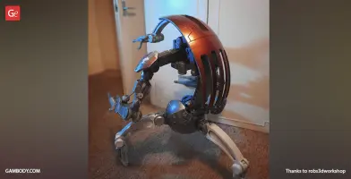
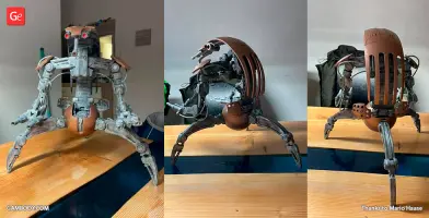
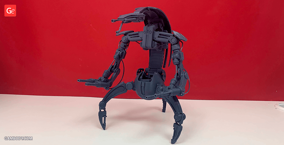
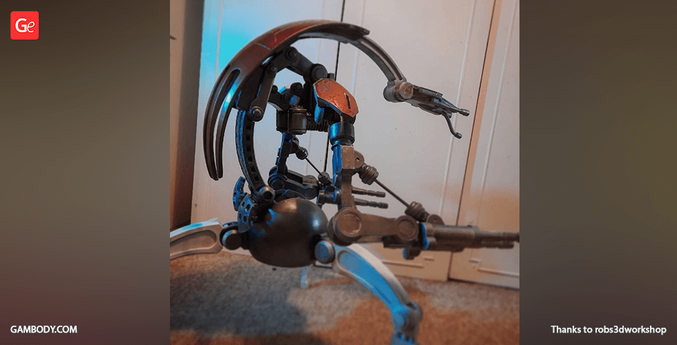
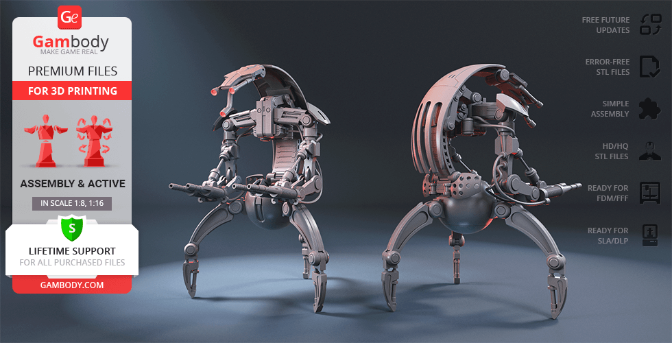
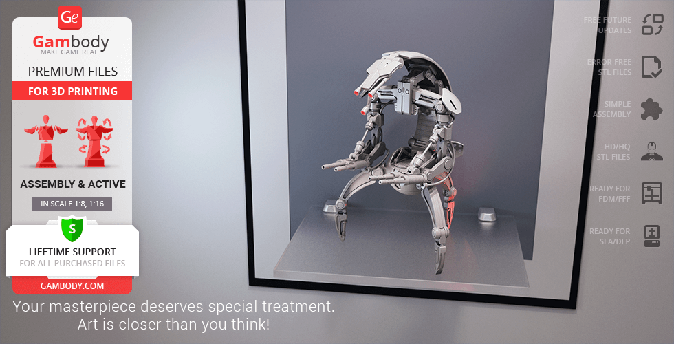
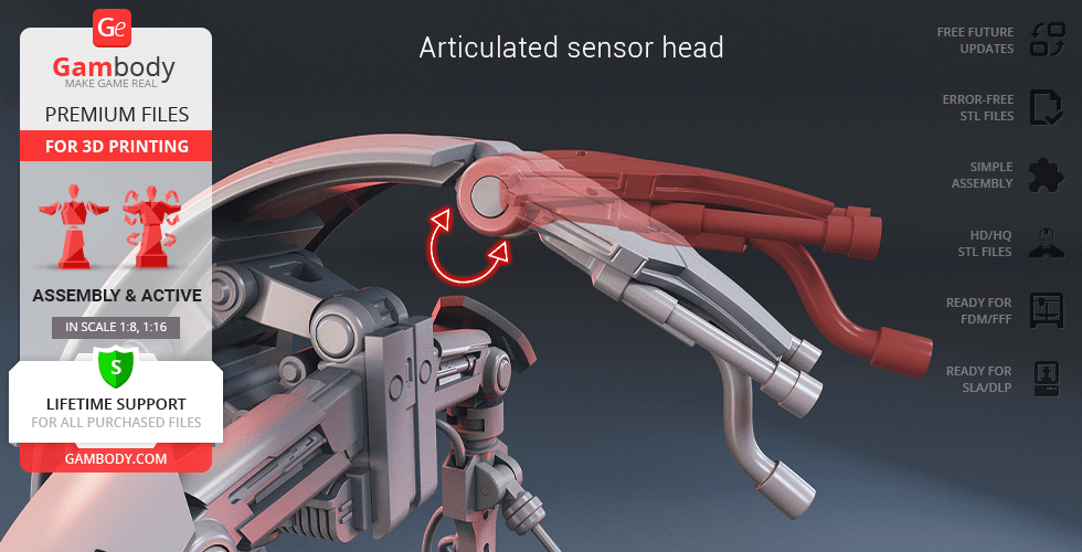
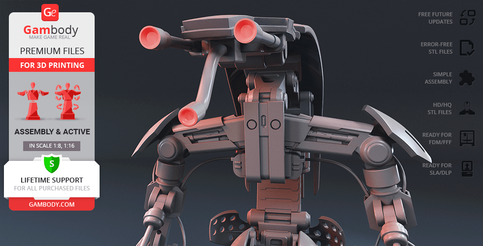
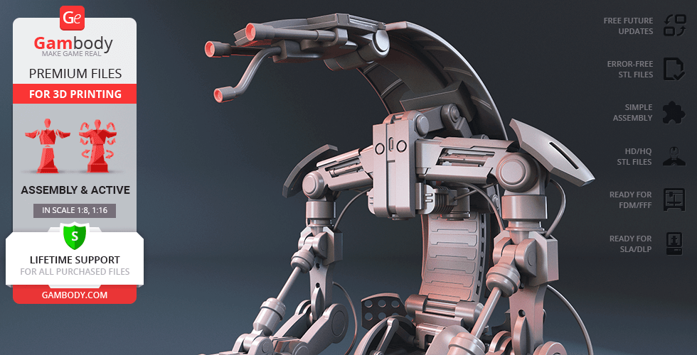
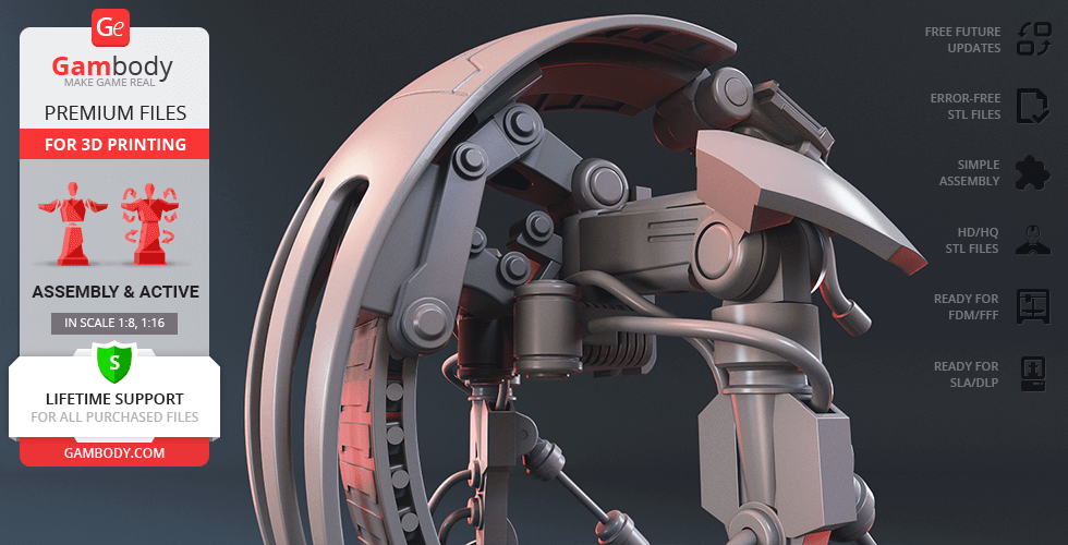
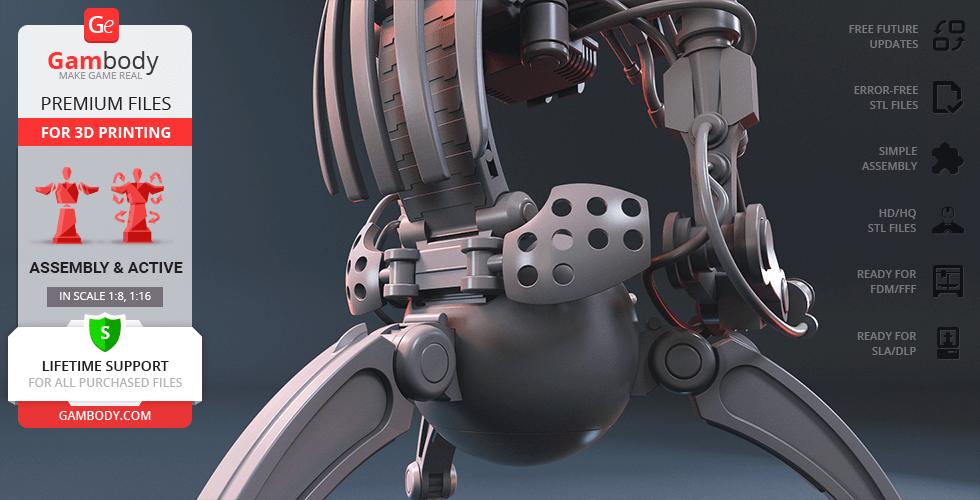
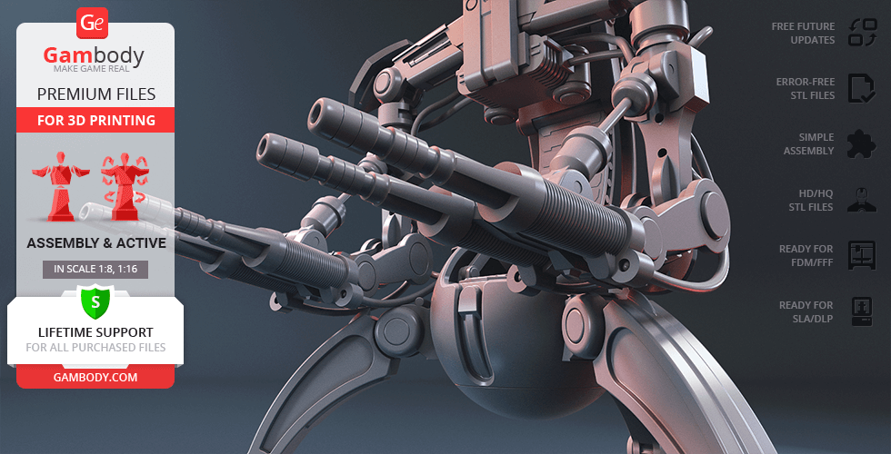
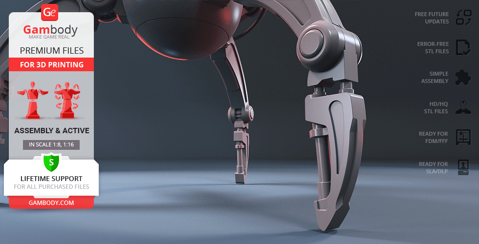
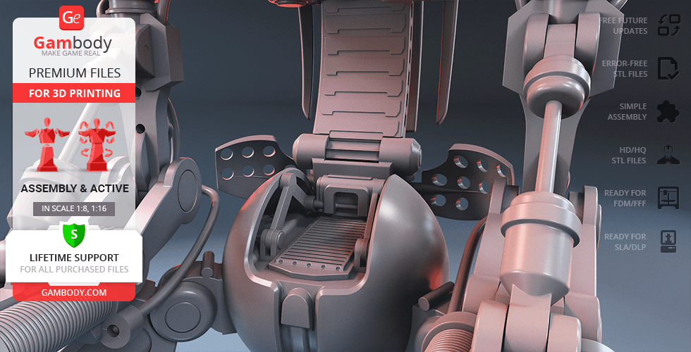
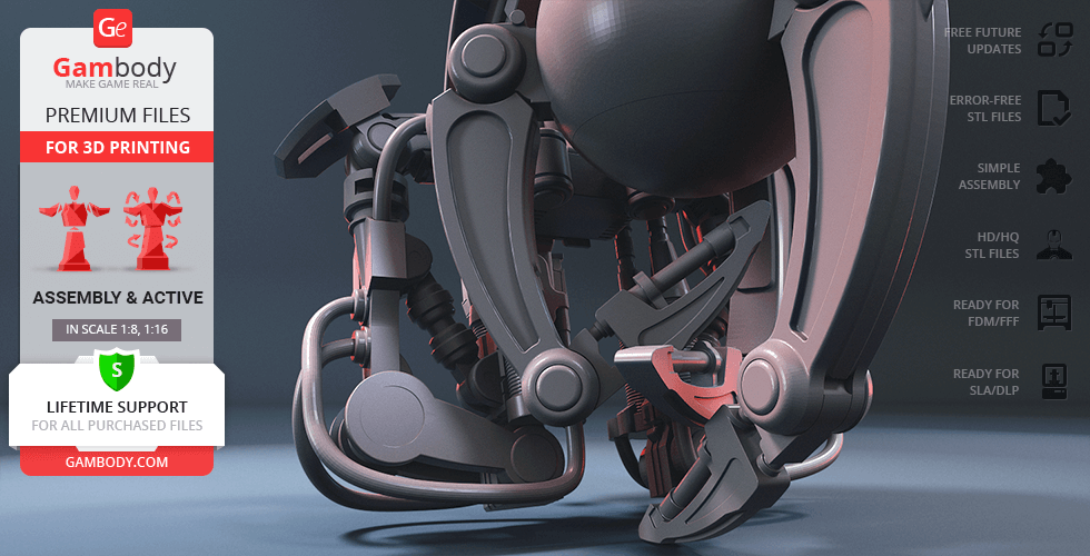
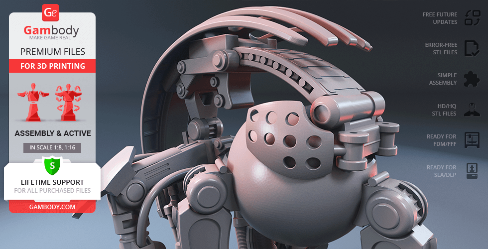
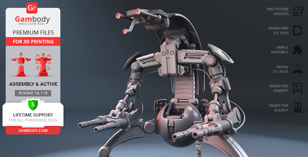
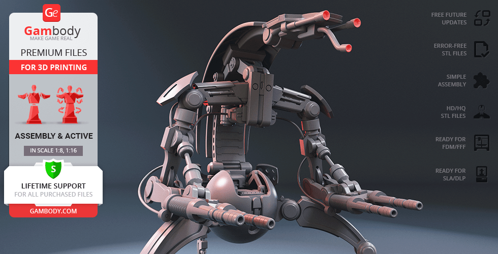
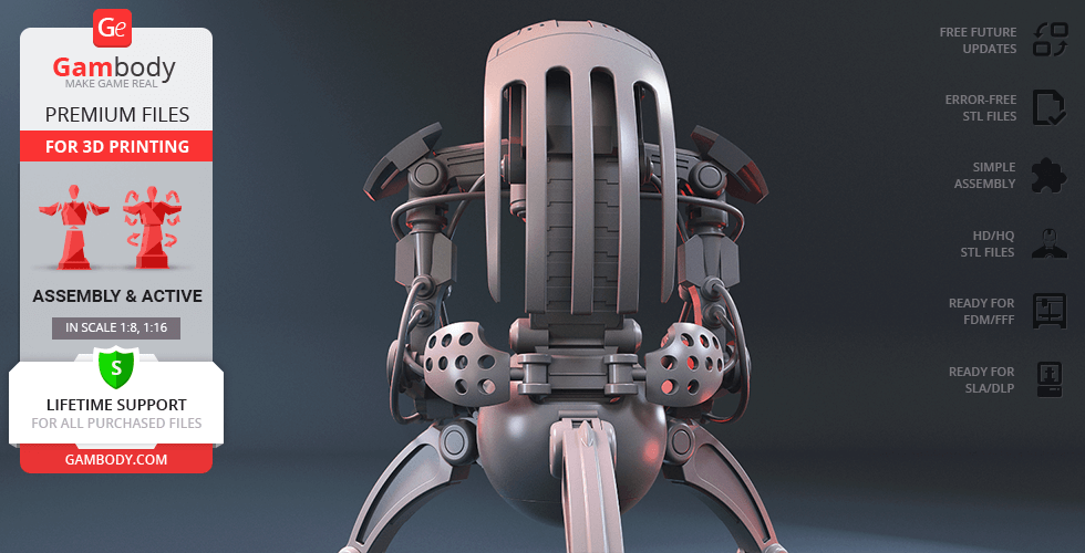
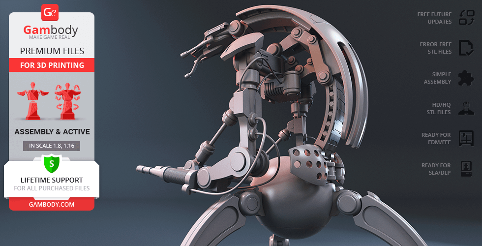
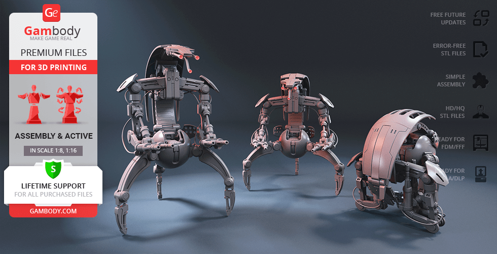
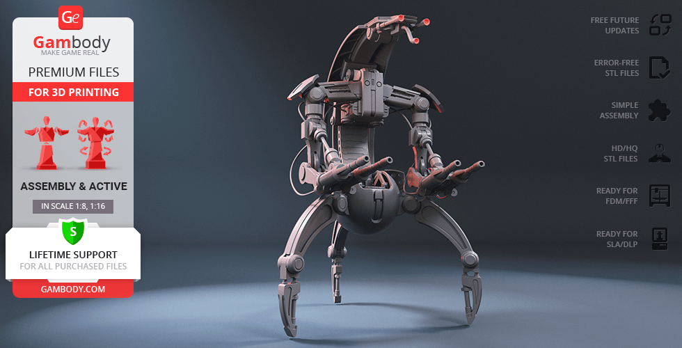
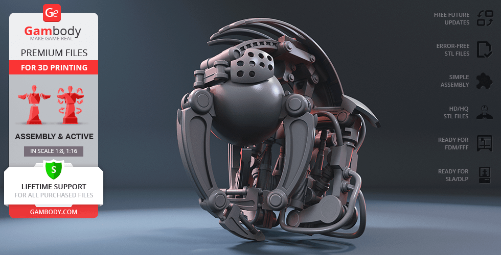
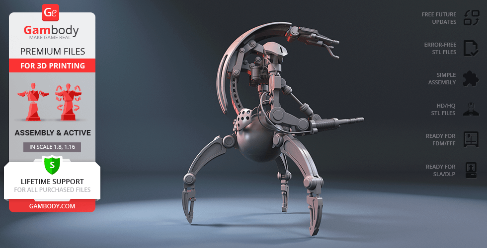
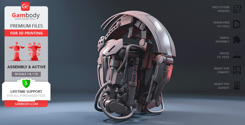
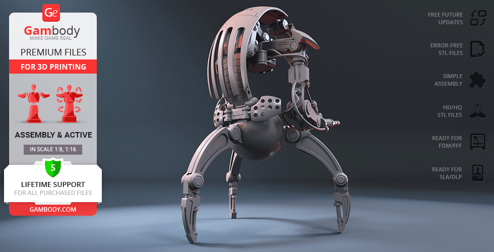
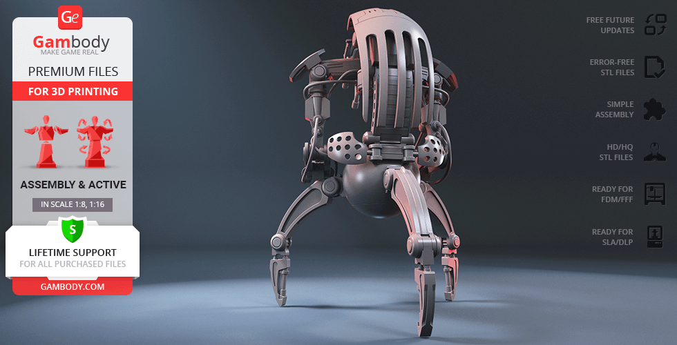
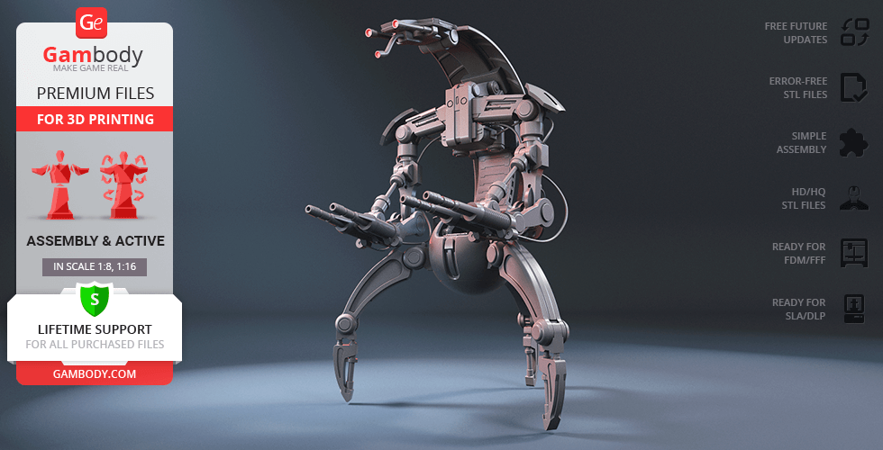
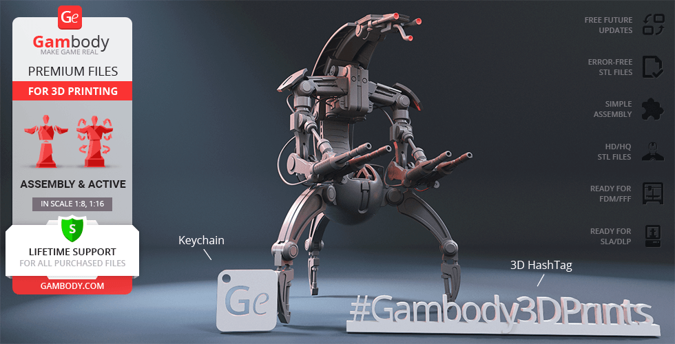
Droidekas are a type of dangerous and deadly droids of the Separatist/CIS army that dramatically roll themselves into a battle and guarantee a merciless attack on the opponents. Unlike Battle Droids that were produced in millions of copies, the Destroyers are far more expensive and extremely effective thanks to their impressive defensive and offensive armament. While standing on its three sharp legs the Droideka can simultaneously utilise its personal deflector shield generator and fire at a target using two twin repeating blaster cannons! After that, the Droideka can swiftly curl into a ball and travel to the next target at a surprisingly rapid pace. The manner of Destroyers’ transformation and transit earned droids the “Rollies” nickname and the reputation of formidable and murderous enemies to stand against. The author of the fantastic Droideka model for 3D printing reportedly dedicated circa 150 hours for the iconic Destroyer to roll into the 3D printed collections of Star Wars fans. Similarly to its on-screen counterpart,the 3D printing Destroyer Droid is heavily armed, carrying twin high-energy blasters on each of its arms. The slim sensor head is equipped with a pair of non-visual composite radiation sensor antennas and a single primary sensor antenna that vaguely resemble the robot’s eyes and nose. The round Droideka’s backshell plate looks perfectly ready to furl into a compact wheel in a matter of seconds making the Destroyer a smaller and speedier target for the opponents. The 3D artist also made sure to equip the droid with the deflector shield projector plates, making the Droideka almost invincible to be defeated by an unprepared brave spirit. Boasting the one-of-a-kind silhouette, the Droideka 3D printing model will become a unique piece of Colicoids’ technology on your display shelf!
ADAPTATION FOR 3D PRINTING
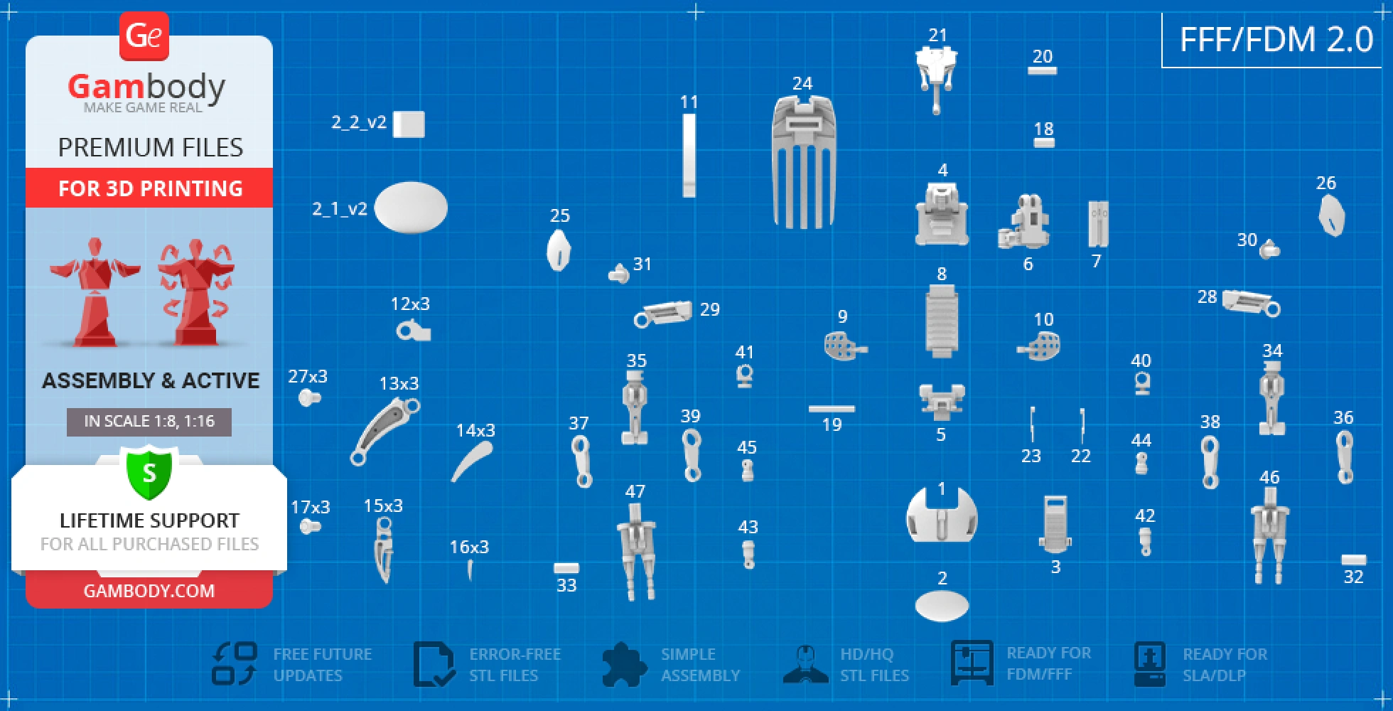
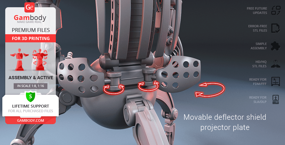
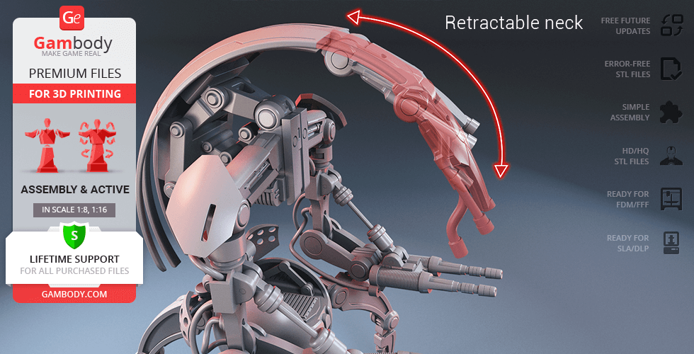
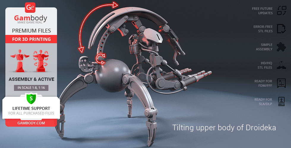
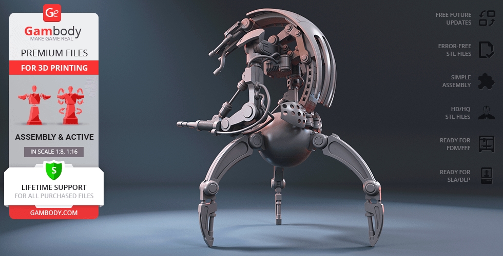
Droideka model for 3D printing is a highly articulated action assembly model and its moderation and adaptation for different types of 3D printers took Gambody team 48 hours in total. In order to ensure the transformation and multidirectional movement of the Destroyer, it was divided into many assembly parts and special mechanisms were introduced into all model’s joints to give you an opportunity to display the droid in a variety of positions, i.e. its backshell plate, sternum plate, censor head, spinal power cell series, twin high-energy blasters, shield plates, legs, foot claws, etc. come as separate assembly parts. The pistons (arm extensor struts) on Droideka’s arms and the neck are retractable. For you to introduce hydraulic cables that connect the Droideka’s parts in the model’s FFF/FDM 1.0 version we recommend that you use the 1.75mm PLA filament and insert its pieces into designated holes that are designed to fit securely the diameter. The assembly of some of Droideka’s parts (like deflector shield projector plate) requires additional “pins”. These pins do not come in STL files as well but can be made out of short pieces of regular 1.75 PLA. All assembly parts are provided in STL files in recommended positions that were worked out in order to ensure the smoothness of the details’ surfaces after printing and so that the 3D printing beginners won't face difficulties when placing the parts on a build plate. The joints that ensure the droid’s movability and transformation are provided as separate files as well for you to be able to print them again if the joints' friction happens to lose rigidity. The cutting in the droid's FFF/FDM and DLP/SLA/SLS versions was made taking into account the peculiarities of each 3D printing technology. We highly recommend that you watch "Assembly video" in the photo preview section before assembling the Droideka. When downloading any model's file you will also receive "Assembly Manual" for FFF/FDM 1.0 and DLP/SLA/SLS 1.0 versions in PDF format.
The model is saved in STL files, a format supported by most 3D printers. All STL files for 3D printing have been checked in Netfabb and no errors were shown.
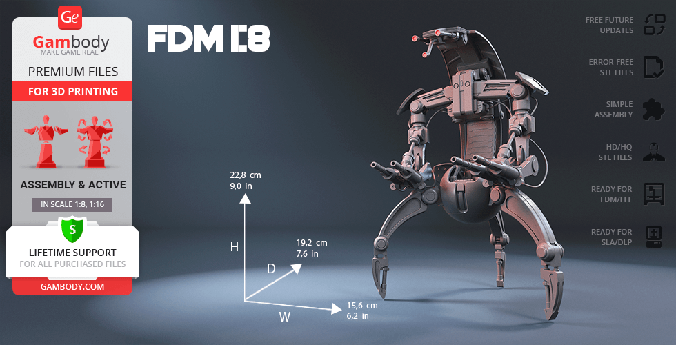
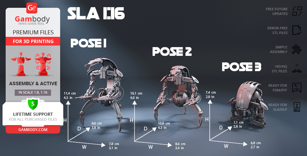
The model's scale was calculated from Droideka's actual height that is 1750 mm. The 3D printing model's chosen scale is 1:8 for the FFF/FDM version and 1:16 for the DLP/SLA/SLS version.
VERSION SPECIFICATIONS
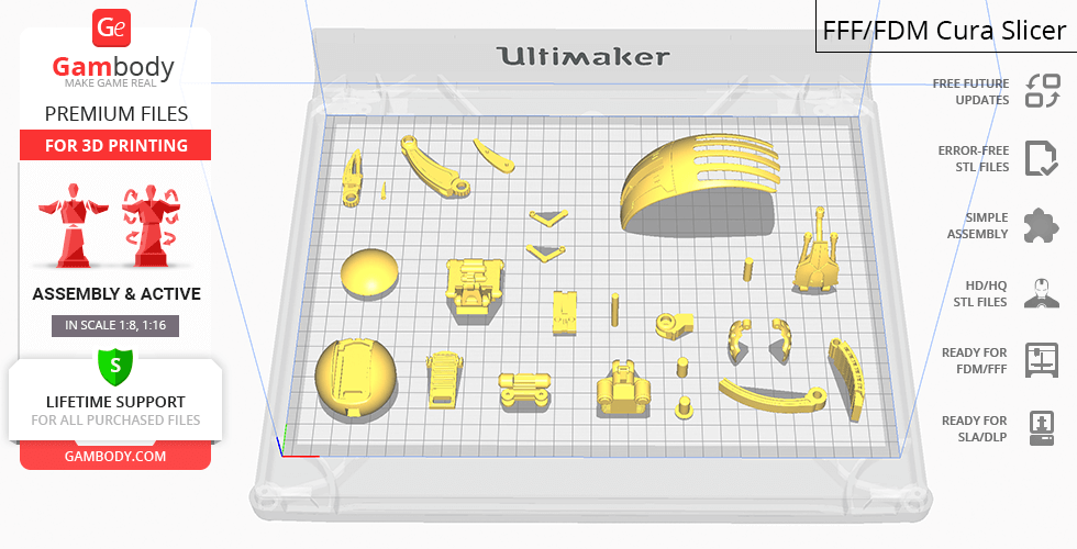
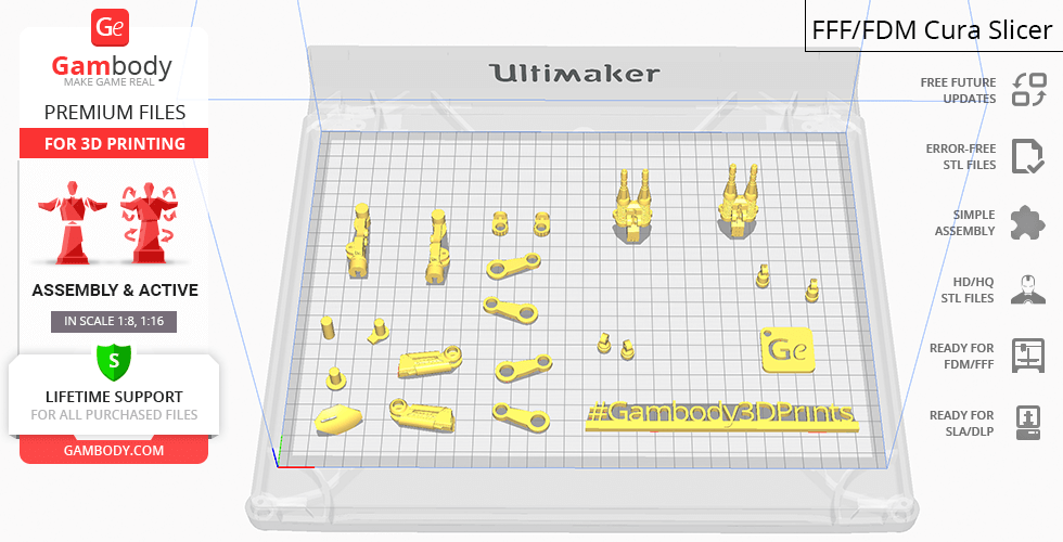
FFF/FDM 1.0 version features:
- Contains 47 parts;
- A printed model is 228 mm tall, 156 mm wide, 192 mm deep;
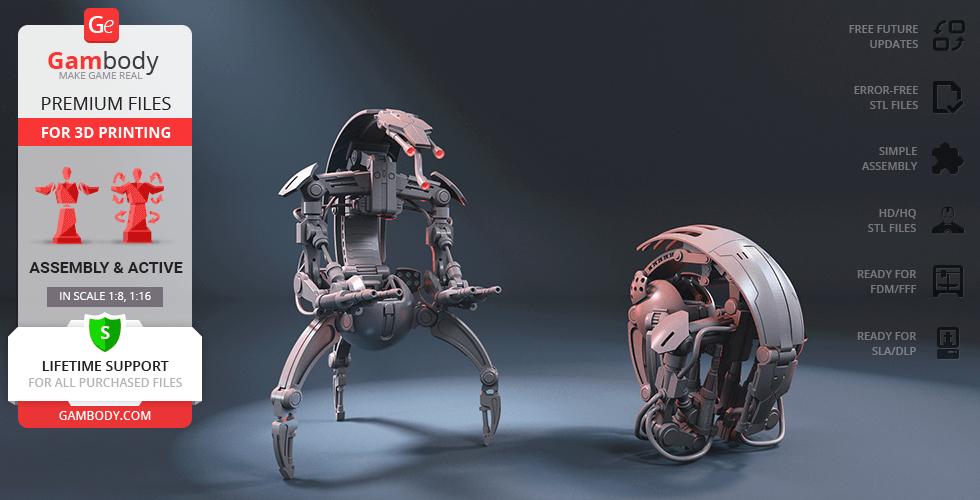
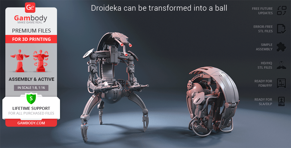
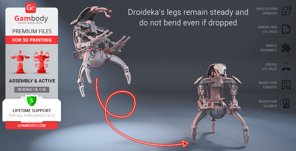
- Droideka can be transformed into a ball;
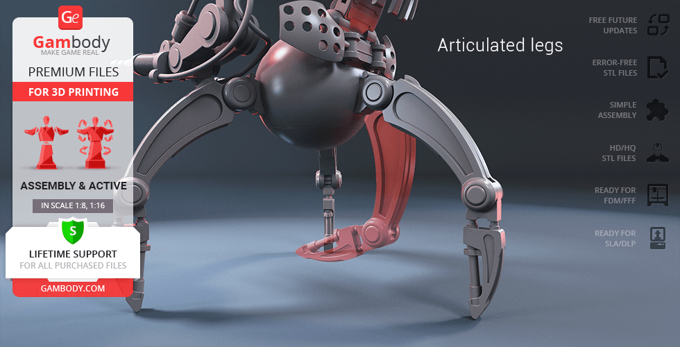
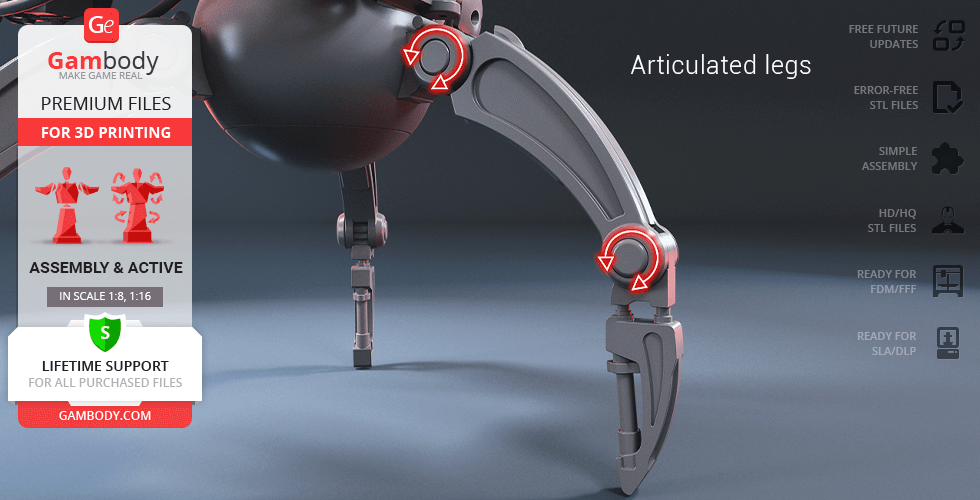
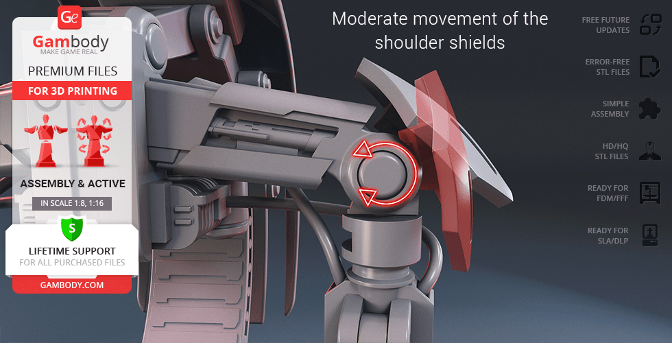
- Each droid's joint (head, neck, "pelvis", sternum, shoulder, elbow, wrist, hip, knee, and shields) is articulated which allows the model's multidirectional movement and transformation;
- This version's assembly requires additional “pins” to secure the parts. These pins do not come in STL files but can be made out of short pieces of regular 1.75 PLA;
- Hydraulic cables that connect the Droideka's parts are not provided with STL files. You can use 1.75mm filament of your choice and insert its pieces into designated holes;
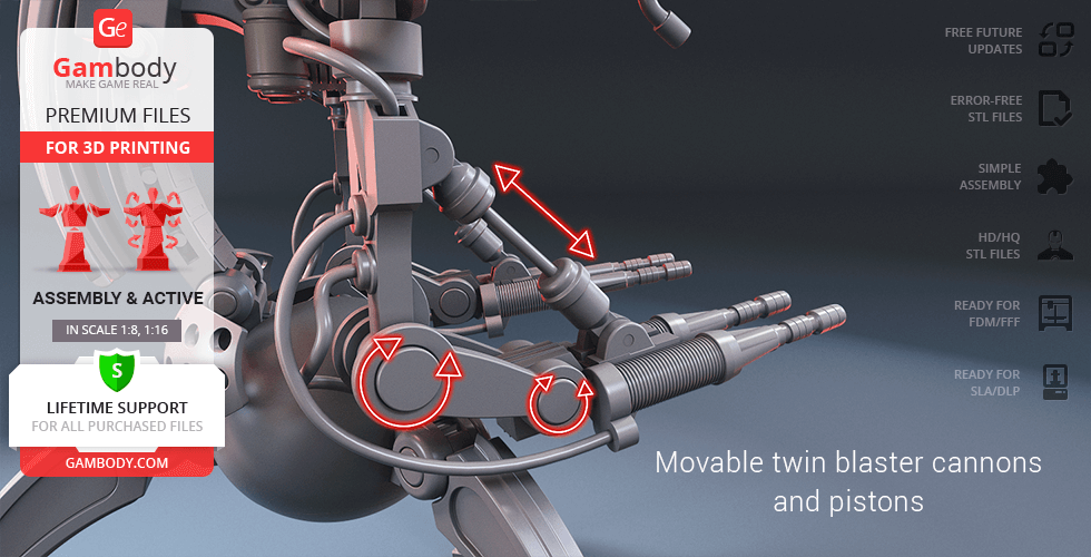
- The pistons on the Droideka's arms are retractable, i.e. they move when you bend the model's articulated arms;
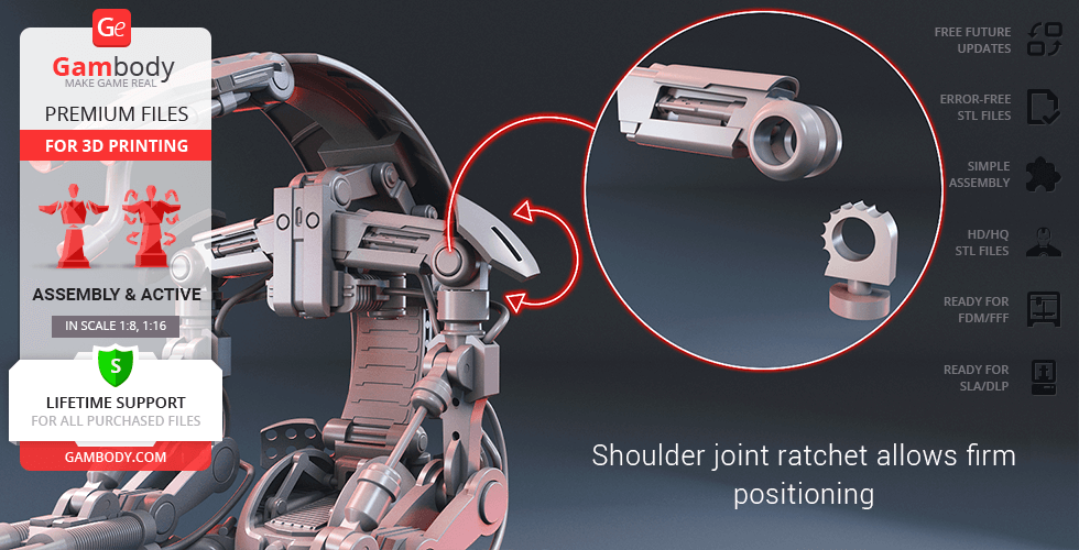
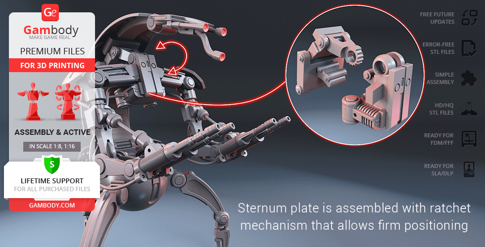
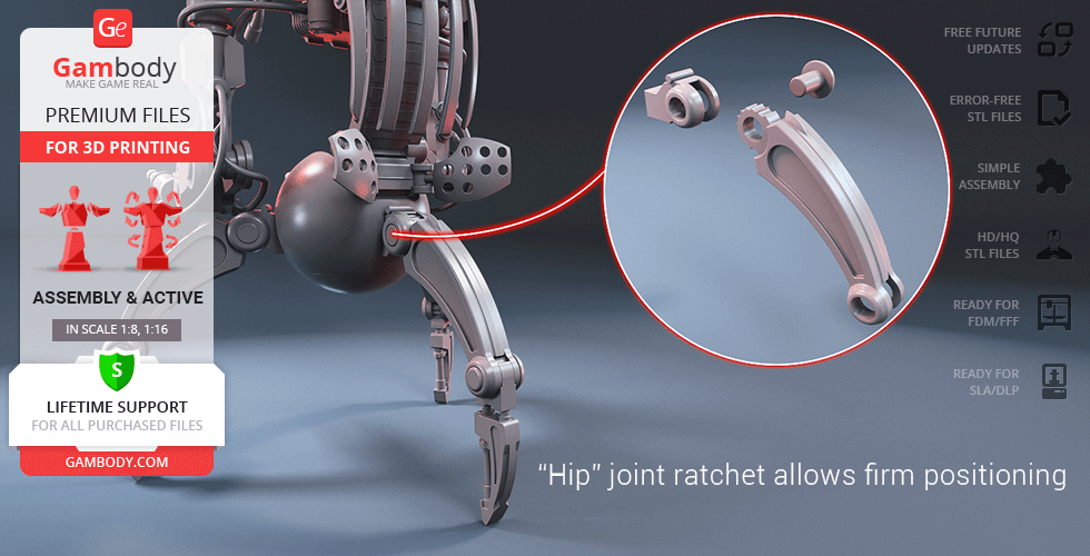
- For the highly articulated Droideka to stand firmly in any position you may choose there was a ratchet mechanism introduced in the model’s shoulder, sternum, and hip joints;
- It is highly recommended that you watch "Assembly video" in the photo preview section and read "Assembly Manual" in PDF before assembling the Droideka;
- All parts are divided in such a way that you will print them with the smallest number of support structures.
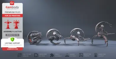
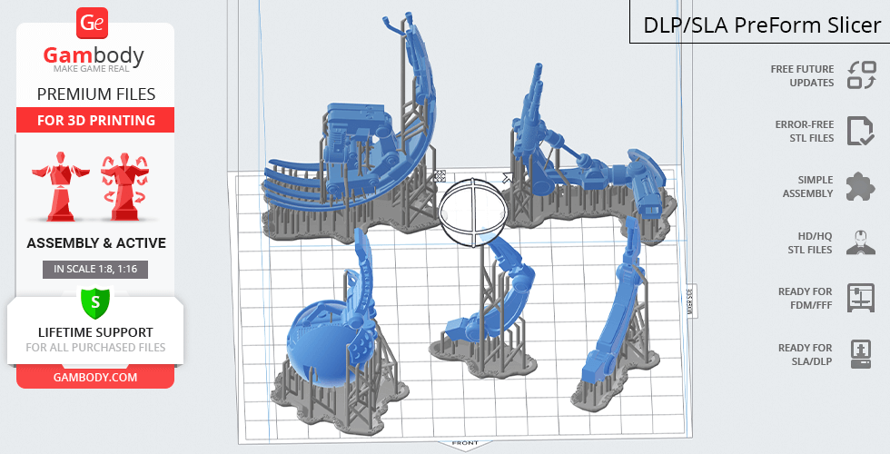
DLP/SLA/SLS 1.0 version features:
- Contains 20 parts;
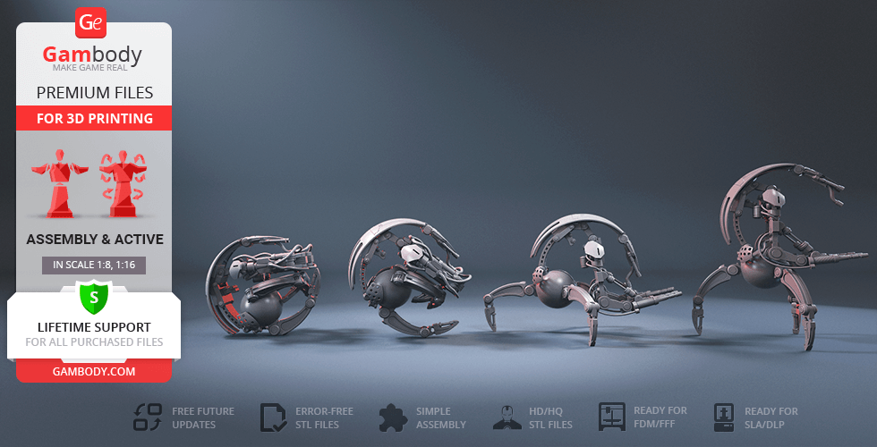
- A printed model in combat stance (P1) is 114 mm tall, 78 mm wide, 96 mm deep;
- intermediate position (P2) is 101 mm tall, 86 mm wide, 109 mm deep;
- wheel form (P3) is 74 mm tall, 68 mm wide, 71 mm deep;
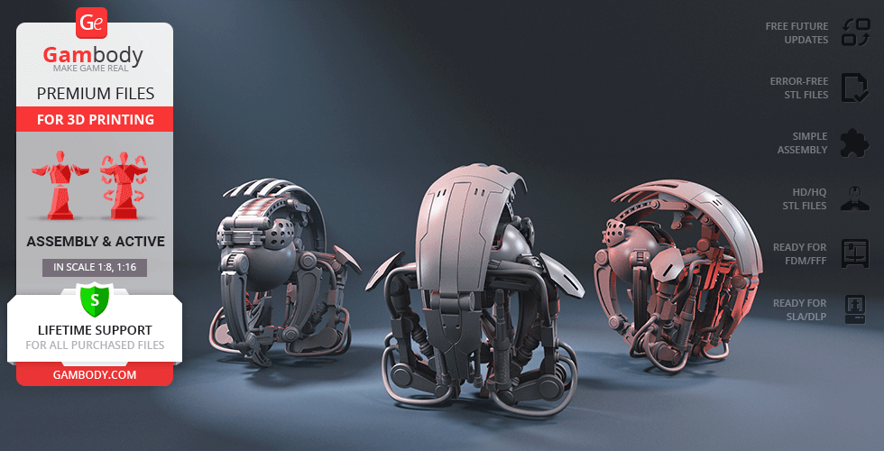
- Comprises parts for you to assemble Droideka in any of three static poses - combat stance, intermediate position, wheel form;
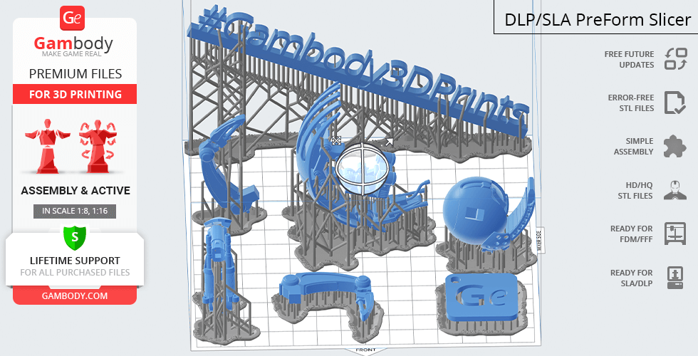
- All parts are divided in such a way to fit the build plates and to ensure that support structures are generated where needed.
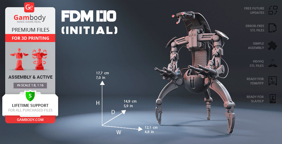
FFF/FDM (Old version), DLP/SLA/SLS (Old version):
- Comes in 1:10 scale;
- Contain 47 and 48 parts respectively;
- When printed both versions stand 177 mm tall, 121 mm wide, 149 mm deep;
- The initial versions of the Droideka model that were uploaded in an incorrect scale;
- These versions' features correspond with the ones of the FFF/FDM 1.0 version.
WHAT WILL YOU GET AFTER PURCHASE?
- STL files of Droideka Model for 3D printing which consist of 67 parts;
- 2 versions of files for this model for FFF/FDM and DLP/SLA/SLS;
- High-poly detailed model of Droideka;
- Assembly Manual for FFF/FDM 1.0 and DLP/SLA/SLS 1.0 versions in PDF format;
- Detailed settings that we provide as a recommendation for Cura , Simplify3D and Slic3r for the best print;
- Full technical support from the Gambody Support Team.
You can get the model of Droideka for 3D Printing immediately after the purchase! Just click the green Buy button in the top-right corner of the model’s page. You can pay with PayPal or your credit card.
Watch the tutorial on how to assemble Droideka 3D Printing Model at Gambody YouTube channel.
Also, you may like other Space War Online 3D Printing Figurines as well as other Droid 3D Printing Models.
_______
FAQ:
Where can I print a model if I have no printer?
How to get started with 3D printing?
How to set up my 3D printer?
How to choose right 3D model print bed positioning?
How to paint printed figurine?
Average customer rating (8 reviews)
5
Ratings breakdown
Click a star rating to filter reviews
Overall experience
Level of detail in the model
4.9
Model cut quality and assembly guide
5
Clarity and accuracy of the model page
5
Level of detail in the model
4.3
Model cut quality and assembly guide
4.6
Clarity and accuracy of the model page
4.7
Level of detail in the model
5
Model cut quality and assembly guide
5
Clarity and accuracy of the model page
5
Level of detail in the model
5
Model cut quality and assembly guide
5
Clarity and accuracy of the model page
5
Level of detail in the model
5
Model cut quality and assembly guide
5
Clarity and accuracy of the model page
5
Level of detail in the model
5
Model cut quality and assembly guide
5
Clarity and accuracy of the model page
5
Level of detail in the model
5
Model cut quality and assembly guide
5
Clarity and accuracy of the model page
5
Level of detail in the model
5
Model cut quality and assembly guide
5
Clarity and accuracy of the model page
5
Level of detail in the model
5
Model cut quality and assembly guide
5
Clarity and accuracy of the model page
5
Below you'll find detailed slicing settings for Bambu Studio 2.0+, Orca Slicer 2.0+, UltiMaker Cura 5.0+, PrusaSlicer 2.0+, Slic3r 1.3+, Simplify3D 5.0+ to help you get the best results when printing this model. These settings are optimized specifically for this 3D model, but please note they may need slight adjustments depending on your printer or filament. When in doubt, refer to your printer's user manual.
To avoid printing issues and achieve the best quality, we highly recommend applying the following settings:
For better quality use 0.12 mm layer height, for fast printing use 0.2 mm layer height. For pins and the Ge connectors, use 0.2 layer height.
120-150% of your Layer Height
But you can paint the seam if you want.
You have to calibrate this parameter
You have to calibrate this parameter
You have to calibrate this parameter
For pins and power elements of the structure, such as the vehicle frame, use 3 loop
Disabled for vehicles and enabled for characters
For 0,2 Layer Height
The parameters in this tab vary greatly, it all depends on the quality of your printer. For example, if you have a classic Ender3, stick to the minimum parameters, but if you have a newer printer, for example Anycubic cobra 3 v2, you can select the maximum recommended values
Settings for advanced users, change these parameters only if you have sufficient 3D printing expertise
Enable this parameter if your model requires supports
We also recommend placing and removing supports manually in some places using special button
1-2 loops for more thick support
Top Z distance = 1-1.3 layer Height. If the supports are hard to remove, try increasing this setting by 0.1-0,4 mm
Bottom Z distance = 1-1.3 layer Height. If the supports are hard to remove, try increasing this setting by 0.1-0,4 mm
You have to calibrate this parameter which one is better for your filament
Increase this parameter if the supports are hard to remove from walls
For PLA and PETG filament types
5-8 mm is optional for small prints that have bad adhesion to the build plate
You have to calibrate this parameter
Read the description on your filament roll
Read the description on your filament roll and increase this parameter for fast printers
Read the description on your filament roll and increase this parameter for fast printers
For better quality use 0.12 mm layer height, for fast printing use 0.2 mm layer height. For pins and the Ge connectors, use 0.2 layer height.
120-150% of your Layer Height
But you can paint the seam if you want.
0.01-0.05 You have to calibrate this parameter
0.01-0.05 You have to calibrate this parameter
0.1-0.2 You have to calibrate this parameter
For pins and power elements of the structure, such as the vehicle frame, use 3 loop
Disabled for vehicles and ships, enabled for characters
For 0,2 Layer Height
For 0,2 Layer Height
The parameters in this tab vary greatly, it all depends on the quality of your printer. For example, if you have a classic Ender3, stick to the minimum parameters, but if you have a newer printer, for example, Anycubic Kobra 3 Or Bambulab A1, you can select the maximum recommended values.
Settings for advanced users, change these parameters only if you have sufficient 3D printing expertise
Enable this parameter if your model requires supports
We also recommend placing and removing supports manually in some places using special button
Top Z distance = 1-1.3 layer Height. If the supports are hard to remove, try increasing this setting by 0.1-0,4 mm
Bottom Z distance = 1-1.3 layer Height. If the supports are hard to remove, try increasing this setting by 0.1-0,4 mm
Increase this parameter if the supports are hard to remove from walls
For PLA and PETG filament types
5-8 mm is optional for small prints that have bad adhesion to the build plate
Read the description on your filament roll
Read the description on your filament roll and increase this parameter for fast printers
You have to calibrate this parameter
Read the description on your filament roll and increase this parameter for fast printers
Read the description on your filament roll
This field is filled in according to your printer specifications when you add it to the slicer.
You can add custom G-code here for the start and end of the print. However, be careful - this is for advanced users only!
You have to calibrate your printer using Ge retraction test models
Retraction Length: For direct-drive setups use 0.5 mm to 2.5 mm; for Bowden extruders use 5 to 7 mm
This is how fast the filament is pulled back—40-60 mm/s for direct drive and 30-50 mm/s for Bowden setups.
You have to calibrate this parameter: Reduce it until the printer starts to hit the parts with the nozzle during printing, then increase it by 0.2.
For better quality use 0.12 mm layer height, for fast printing use 0.2 mm layer height. For pins and the Ge connectors, use 0.2 layer height.
120-150% of your Layer Height
To increase the strength of the print parts, use wall line count: 3
For pins and connectors use 50% Infill
These parameters are for standard PLA plastic. If you are using a different type of plastic, check the printing temperature recommended by the manufacturer. Also, read the description on your filament spool. For fast printers, add +30 °C to the current parameters.
The parameters in this tab vary greatly, it all depends on the quality of your printer. For example, if you have a classic Ender3, stick to the minimum parameters, but if you have a newer printer, for example Anycubic cobra 3 v3, you can select the maximum recommended values
Settings for advanced users, change these parameters only if you have sufficient 3D printing expertise.
You need to calibrate this parameter using Gambody test models. These values are average values for a Direct Drive extruder; for a Bowden extruder, the values should be increased.
You need to calibrate this parameter using Gambody test models. These values are average values for a Direct Drive extruder; for a Bowden extruder, the values should be increased.
Use this value other than 0 if your nozzle catches on the internal infill during travel moves. Try to keep this value as low as possible in height.
Use normal supports to support large, straight surfaces (most mechanical or technical parts).
You have to calibrate this parameter according to the capabilities of your printer and your filament, using a Gambody test models.
Use 1 instead of 0 if your supports are thin and tall. They will be harder to remove, but much stronger.
Top Z distance = 1-1.3 layer Height. If the supports are hard to remove, try increasing this setting by 0.1-0,4 mm
Increase this parameter if the supports are hard to remove from walls
Use tree supports to support complex objects, such as characters.
You have to calibrate this parameter according to the capabilities of your printer and your filament, using a Gambody test models.
Top Z distance = 1-1.3 layer Height. If the supports are hard to remove, try increasing this setting by 0.1-0,4 mm
Increase this parameter if the supports are hard to remove from walls
Use a skirt for all parts when printing on outdated printers.
Use a brim when printing thin but tall parts, as well as parts with a small bed adhesion area.
For better quality use 0.12 mm layer height, for fast printing use 0.2 mm layer height. For pins and the Ge connectors, use 0.2 layer height.
120-150% of your Layer Height
for 0.2 Layer Height
But you can paint the seam if you want.
(for PLA and PETG)
(5-8 mm is optional for small prints that have bad adhesion to the build plate)
Enable this parameter if your model requires supports
(45-50 degree)You have to calibrate this parameter according to the capabilities of your printer
and your filament, using a Gambody test models.
Top contact Z distance = 1-1.3 layer Height. If the supports are hard to remove, try
increasing this setting by 0.1-0,4 mm
Top contact Z distance = 1-1.3 layer Height. If the supports are hard to remove, try
increasing this setting by 0.1-0,4 mm
Increase this parameter if the supports are hard to remove from walls
The parameters in this tab vary greatly, it all depends on the quality of your printer. For example, if you have a classic Ender3, stick to the minimum parameters, but if you have a newer printer, for example Anycubic cobra 3 v3, you can select the maximum recommended values
Settings for advanced users, change these parameters only if you have sufficient 3D printing expertise. Use the minimum value for outdated printers without acceleration calibration, and the maximum value for modern printers if you need it.
These settings only work for 3D printers with multiple extruders
You can try setting all parameters in this section, except the First layer, to values between 0.75% of your nozzle diameter and 1.25% of your nozzle diameter. Adjusting them will help you work out the optimal parameters for the best quality for your print. As for the First layer, you can set it to 150% of the diameter of your nozzle for better adhesion to the build plate (for a nozzle with a diameter of 0.4 mm, the First layer extrusion width can be from 0.3 mm to 0.5 mm)
For better printing quality you have to calibrate this parameter using Gambody test model.
Check your filament manufacturer's temperature recommendations on the spool.
Cooling parameters depends on the material you use for printing.
*for PLA
For better quality use 0.12 mm layer height, for fast printing use 0.2 mm layer height. For pins and the Ge connectors, use 0.2 layer height.
120-150% of your Layer Height
For 0.12 Layer Height
For 0.12 Layer Height
For pins and connectors use 50% Infill
Use skirt for outdated 3d printers
(5-8 mm is optional for small prints that have bad adhesion to the build plate)
Enable this parameter if your model requires supports
(45-60 degree)You have to calibrate this parameter according to the capabilities of your printer and your filament, using a Gambody test models
Contact Z distance = 1-1.3 layer Height. If the supports are hard to remove, try increasing this setting by 0.1-0,4 mm
The parameters in this tab vary greatly, it all depends on the quality of your printer. For example, if you have a classic Ender3, stick to the minimum parameters, but if you have a newer printer, for example Anycubic cobra 3 v3, you can select the maximum recommended values
Settings for advanced users, change these parameters only if you have sufficient 3D printing expertise. Use the minimum value for outdated printers without acceleration calibration, and the maximum value for modern printers if you need it.
You have to calibrate this parameter from 0.9 to 1.1 according to the capabilities of your printer and your filament, using a Gambody test models.
Check your filament manufacturer's temperature recommendations on the spool.
Cooling parameters depends on the material you use for printing.
Calibrate this value if you need to reduce or improve the adhesion between the plastic and the heat bed
Your current nozzle diameter
You need to calibrate this parameter using Gambody test models. These values are average values for a Direct Drive extruder; for a Bowden extruder, the values should be increased.
Your current nozzle diameter
You have to calibrate this parameter using Gambody test models.
You need to calibrate this parameter using Gambody test models. These values are average values for a Direct Drive extruder; for a Bowden extruder, the values should be increased.
For better quality use 0.12 mm layer height, for fast printing use 0.2 mm layer height. For pins and the Ge connectors, use 0.2 layer height.
For 0,2 Layer Height
For 0,2 Layer Height
To increase the strength of the print parts, use Outline Perimeters: 3
You can enable this parameter to print rounded or spherical models, as well as character models.
Use this option only if your parts are too tight. but better calibrate your printer extrusion
Use this option only if your parts are too tight. but better calibrate your printer extrusion
Use 2 and more if you want to create skirt instead brim
1-2 for skirt and 10-20 for brim
Use for wipe nozzle if you need
Use For ABS filament
For pins and connectors use 50% Infill
Top Z distance = 1-1.3 layer Height. If the supports are hard to remove, try increasing this setting by 0.1-0,4 mm
Calibrate your filament and detect optimal temperature for it
Average temperature for PLA filament
The parameters in this tab vary greatly, it all depends on the quality of your printer. For example, if you have a classic Ender3, stick to the minimum parameters, but if you have a newer printer, for example Anycubic cobra 3 v3, you can select the maximum recommended values
Settings for advanced users, change these parameters only if you have sufficient 3D printing expertise.