


Files
3D model format
Stereolithography (.stl)
Total files
Slicer settings
Mesh error check
Netfabb
Support
Lifetime support from Gambody team
Update requests
Available to verified buyers
Model complexity
Advanced: may require tuning print settings or support placement, plus precise fitting, gluing, or sanding.
Model versions
FFF/FDM
Assembly method
not specified
Features
DLP/SLA
Assembly method
not specified
Features
FFF/FDM
Assembly method
not specified
Features
DLP/SLA
Assembly method
not specified
Features
Additional details
Part of diorama
No
Special pack included
No
You will get instant access to the STL files of R2-D2 3D Printing Model | Assembly + Action after completing your purchase. Simply add the model to your cart and check out using PayPal, credit or debit card, Apple Pay, Google Pay, Alipay, or other available payment methods.
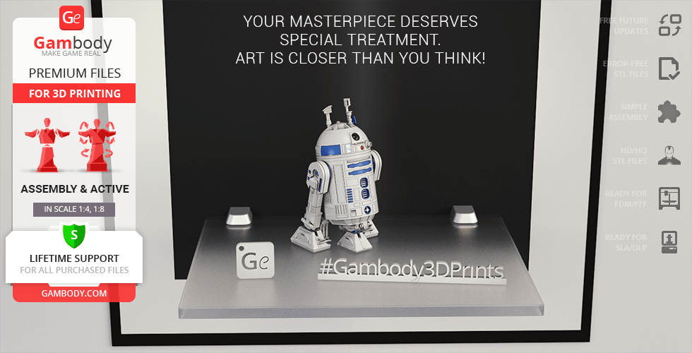
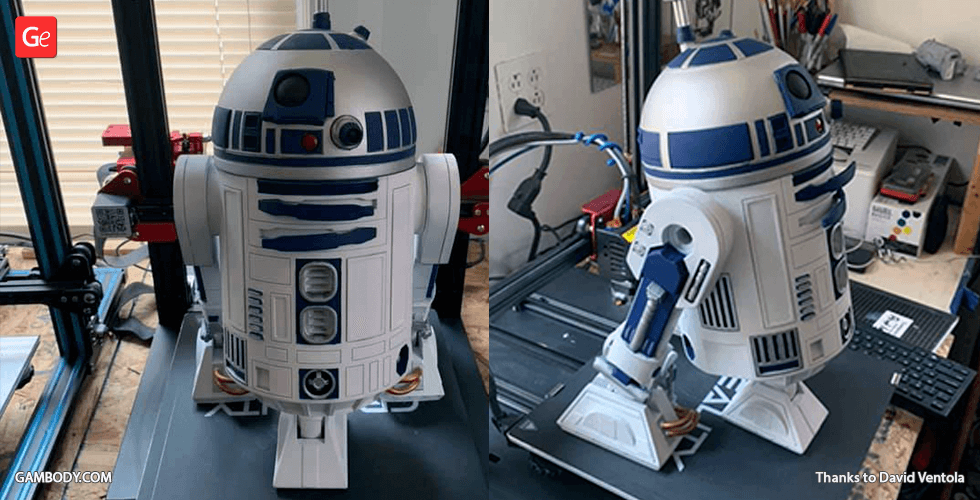
Watch the assembly video for R2-D2 3D Printing Model | Assembly + Action, and explore more tutorials, behind-the-scenes content, 3D printing timelapses, and painting guides on the official Gambody YouTube channel.
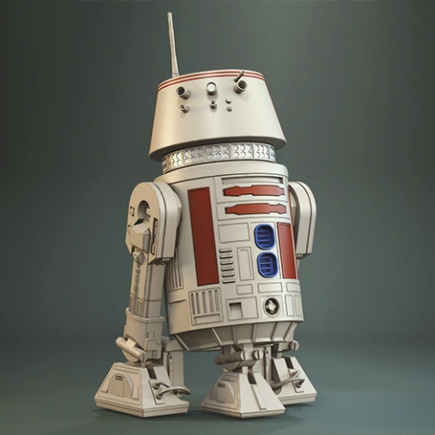
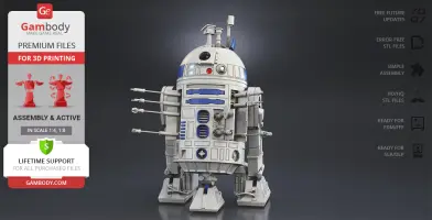
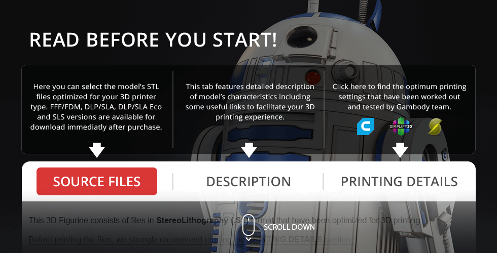
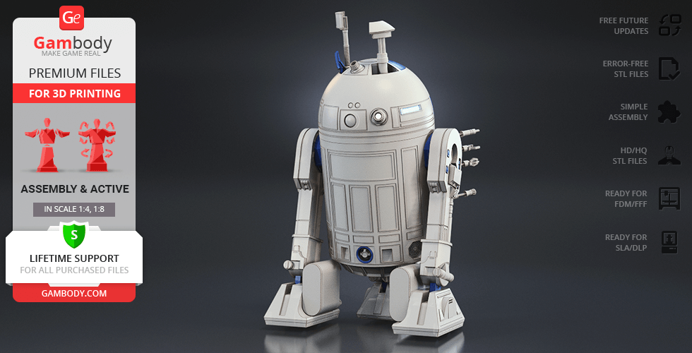
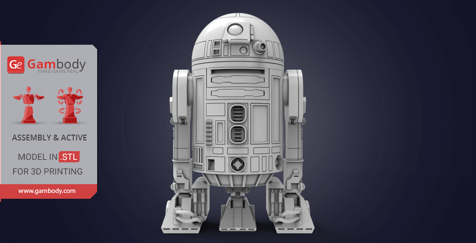
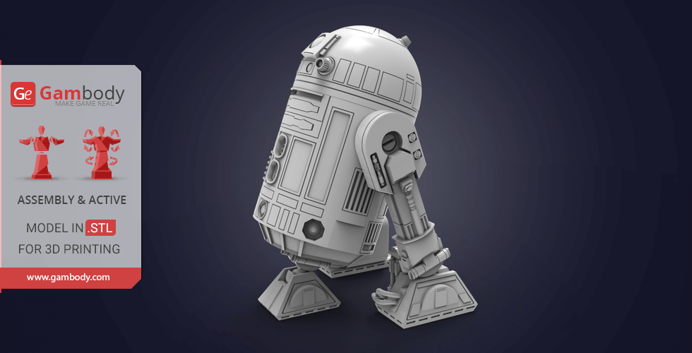
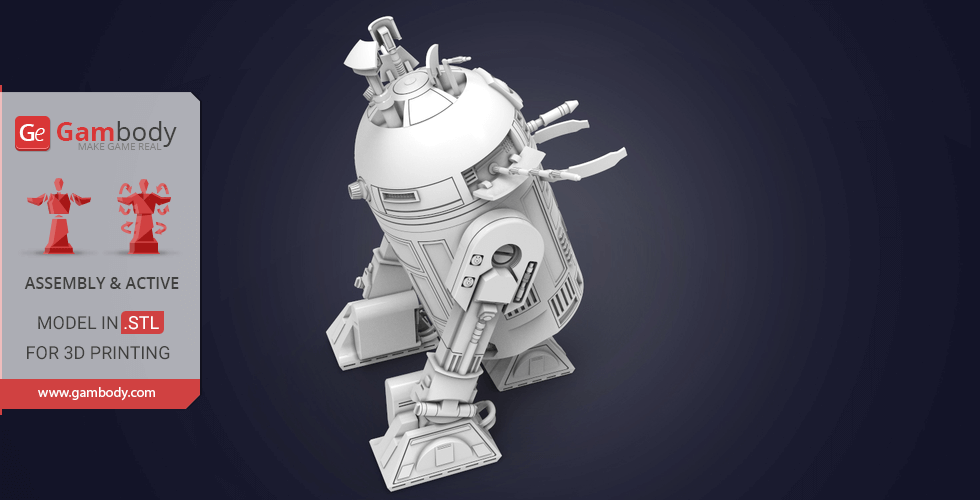
This 3D Model of R2-D2 Droid from Star Wars consists of files in StereoLithography (.Stl) format that is optimized for 3D printing.
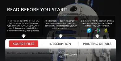
Before printing the files, we strongly recommend reading the PRINTING DETAILS section.
WHAT WILL YOU GET AFTER PURCHASE?
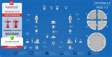
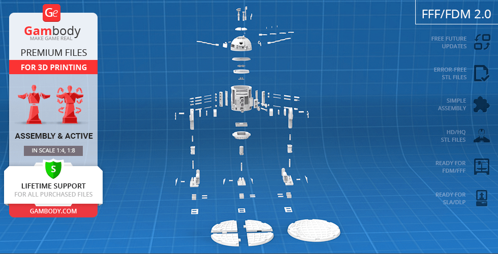
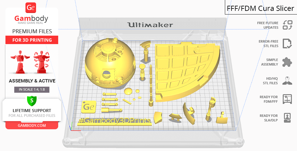
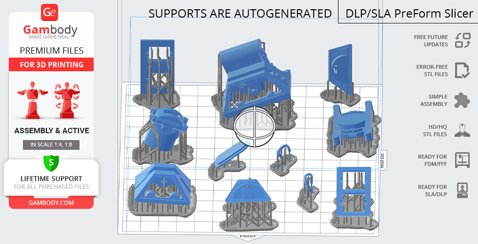
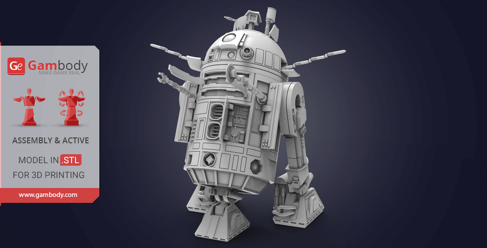
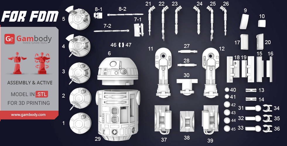
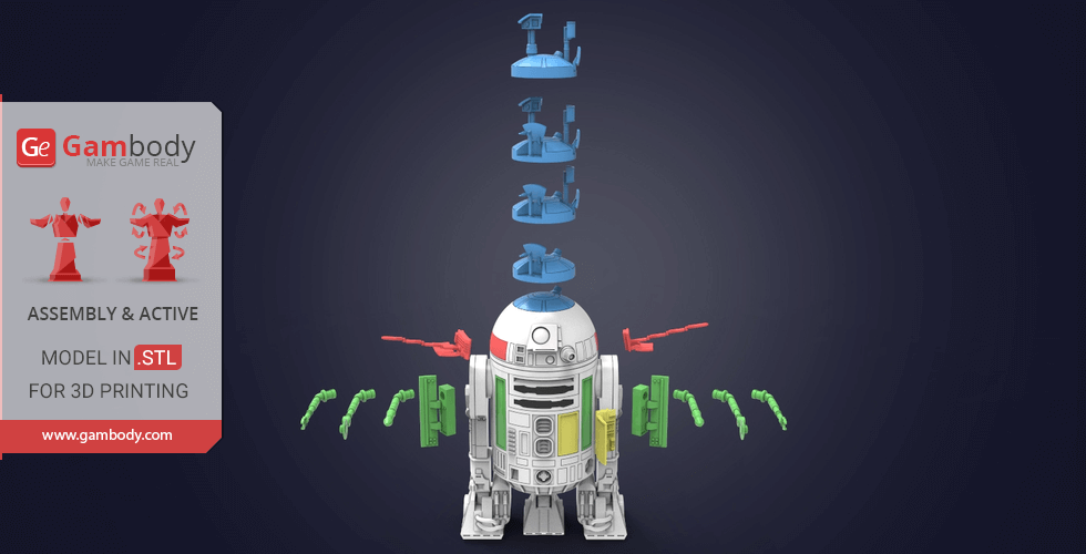
- 4 versions of R2-D2 STL files for FFF/FDM and DLP/SLA/SLS - files for both versions are available for download after the purchase
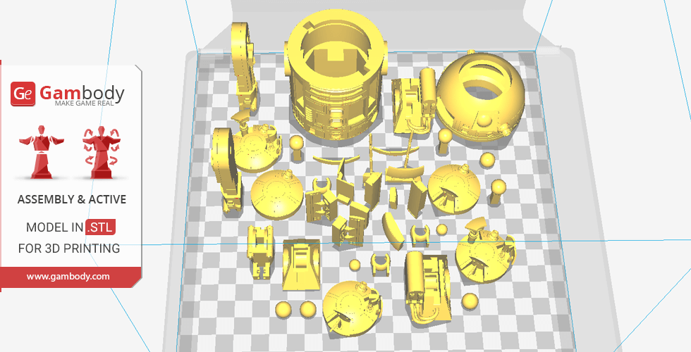
- STL files of high-poly R2-D2 Droid 3D Model for 3D printing consist of 220 parts
- Sizes:
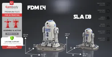
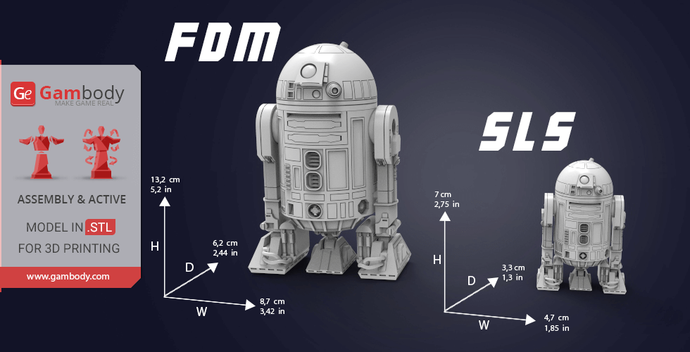
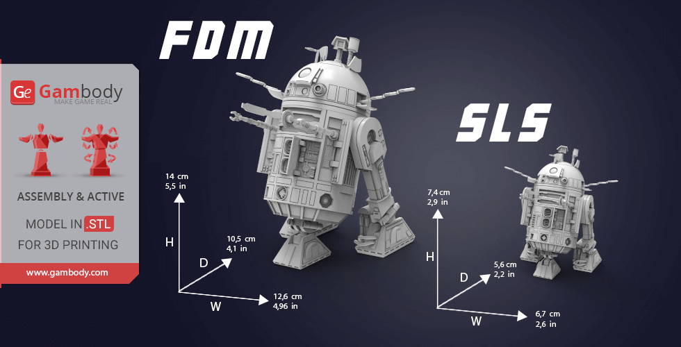
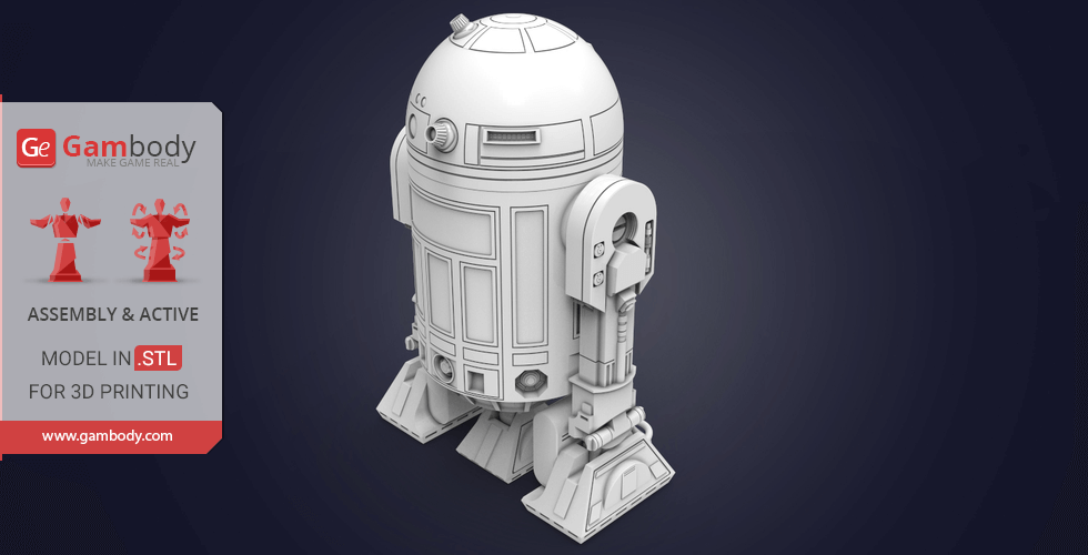
- FFF/FDM: 276 mm tall, 302 mm wide, 302 mm deep
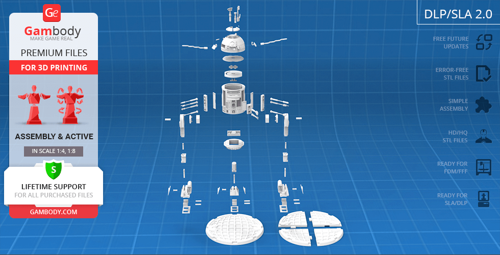
- DLP/SLA/SLS: 138 mm tall, 151 mm wide, 151 mm deep
- Assembly Manual for FFF/FDM 2.0 and DLP/SLA/SLS 2.0 versions in PDF format
- Detailed settings that we provide as a recommendation for Cura, Simplify3D and Slic3r for the best print- Full technical support from the Gambody Support Team
Detailed information about this 3D printing model is available in the DESCRIPTION section.
Before printing, take a look at Printing Details for recommended settings and tips to achieve better results.
ABOUT THIS 3D MODEL
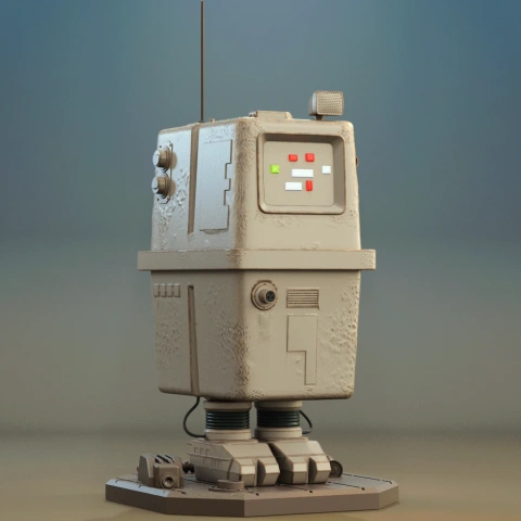
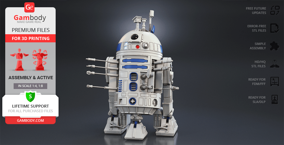
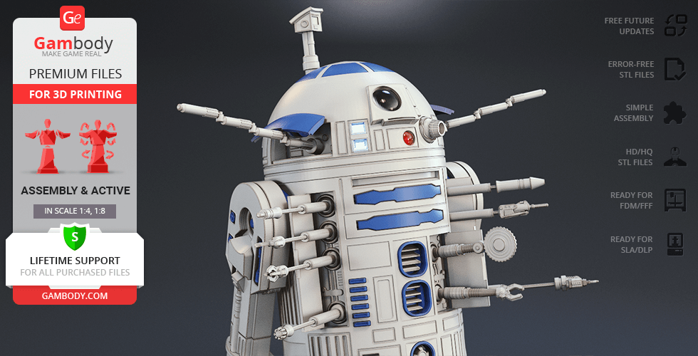
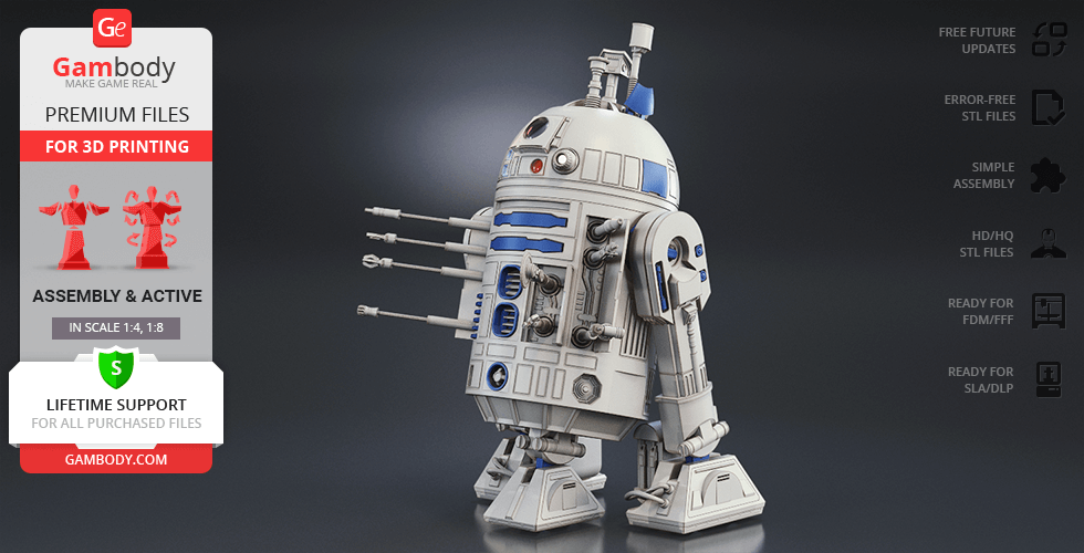
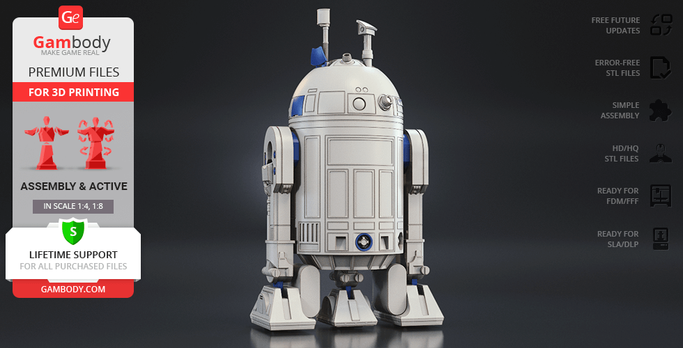
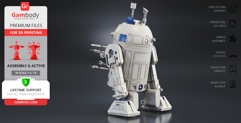
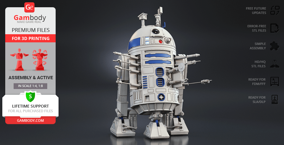
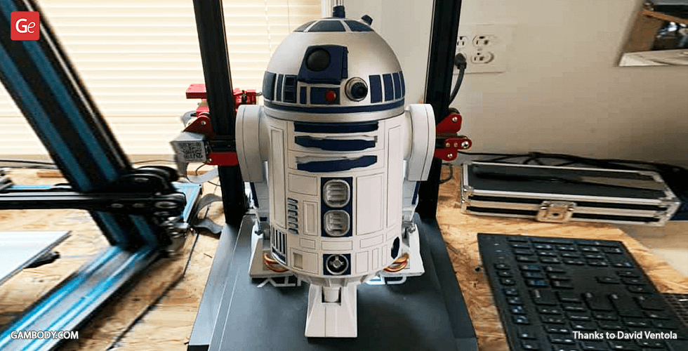
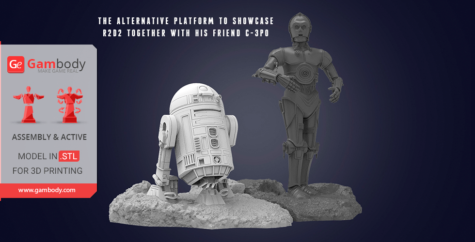
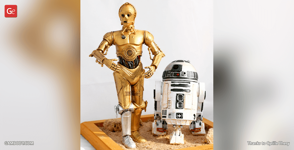
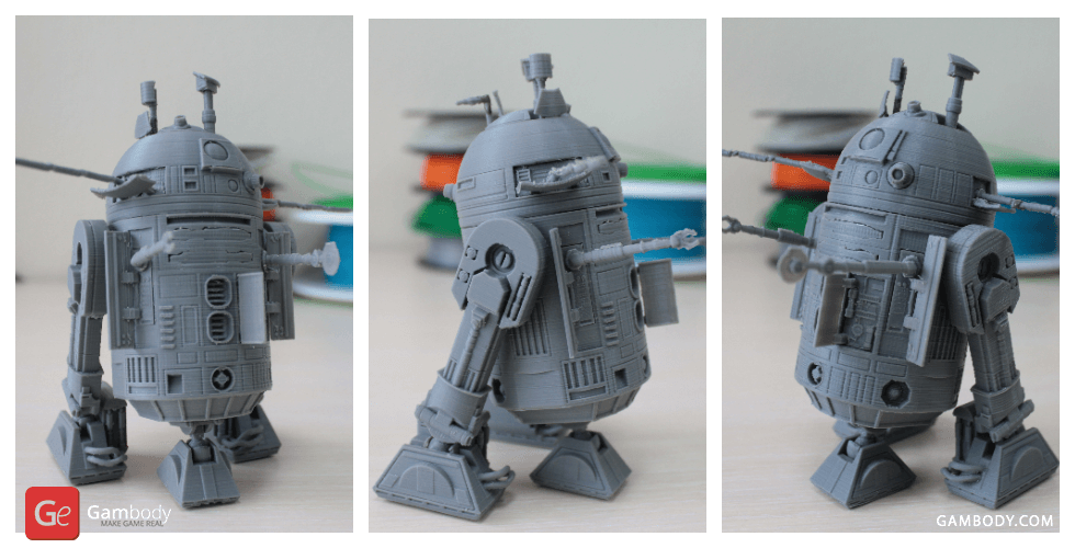
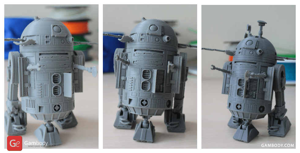
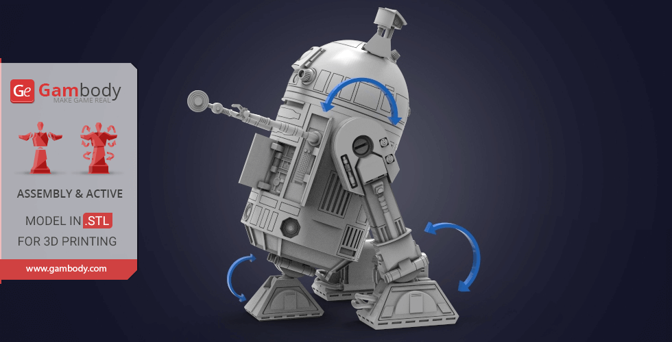
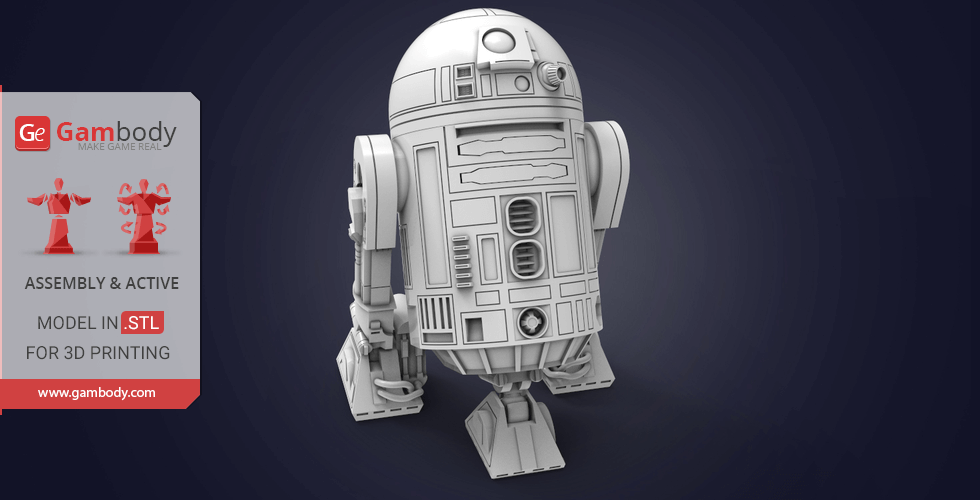
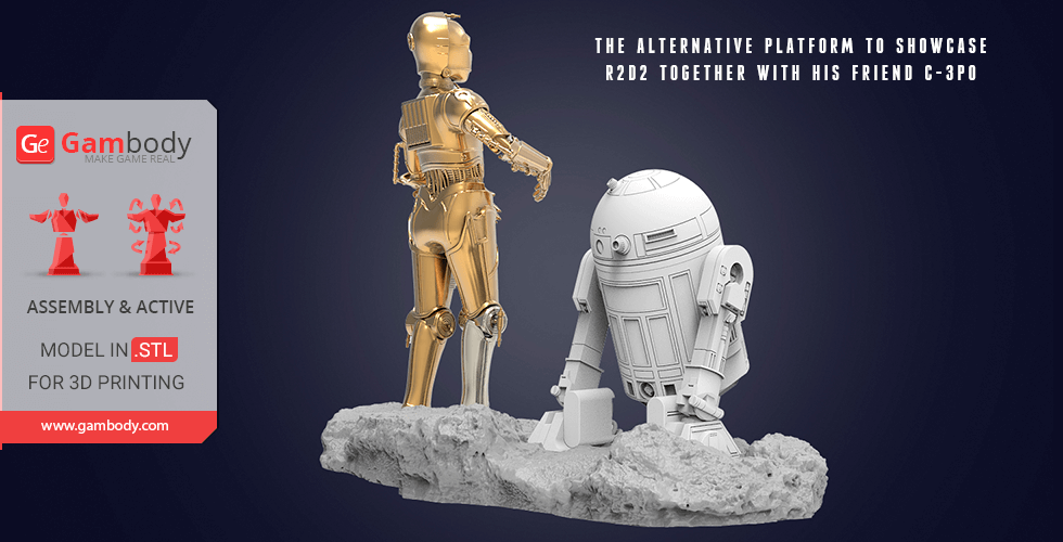
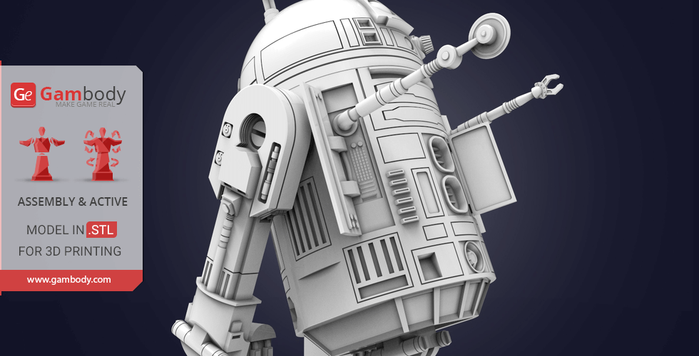
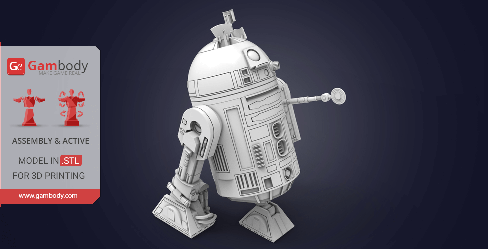
R2-D2 is a resourceful astromech droid from the royal house of Naboo, a mobile Swiss Army knife who is always ready to rush into danger to save the Galaxy. R2 has always boasted a rich arsenal of various gadgets, sensors and utility arms that help him be a superior spacecraft mechanic and an excellent specialist in interaction with computers. The brave and adventurous R2-D2 seems to always know what tool to pull out to save the day and change the course of the Galaxy’s history!
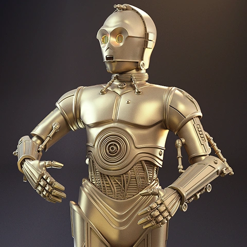
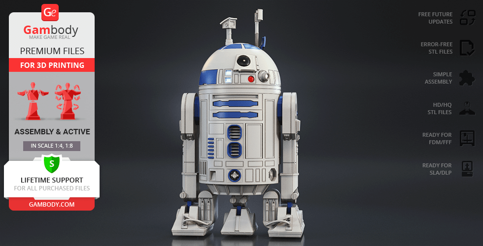
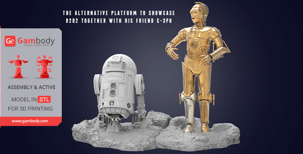
Due to the fact that R2’s memory was never fully erased, nor did he ever receive new programming, the silver blue domed droid often takes the initiative and shows his independent attitude in pivotal situation. These qualities are easily the reason why R2-D2 is so well-liked by Star Wars fans of all ages! Thanks to the efforts of our contributing 3D artist, the incredible astromech droid for 3D printing with a ton of cool gadgets and features joins his best friend C-3PO in our stunning SW collection!
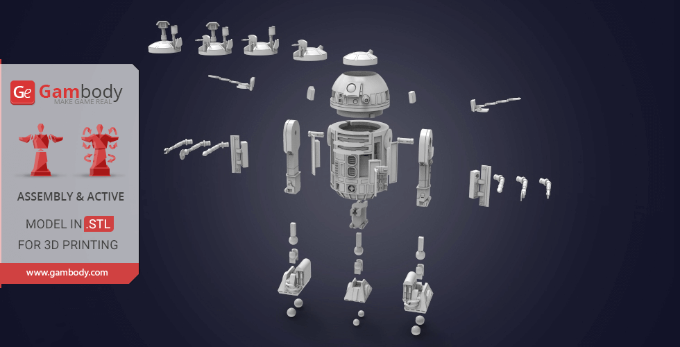
ADAPTATION FOR 3D PRINTING (FFF/FDM 2.0, DLP/SLA/SLS 2.0)
R2-D2 for 3D printing is a active assembly model and its updating and adaptation for different types of 3D printers took Gambody team 55 hours in total. Due to the fact that this model was first released on Gambody back in 2017, for all Star Wars fans to print the best astromech droid possible, the model was upgraded from the ground up, cut into assembly parts anew, and adapted for different types of 3D printers taking into account the present-day technology advancements.
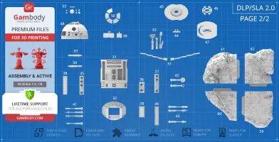
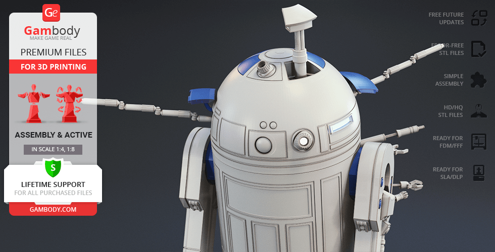
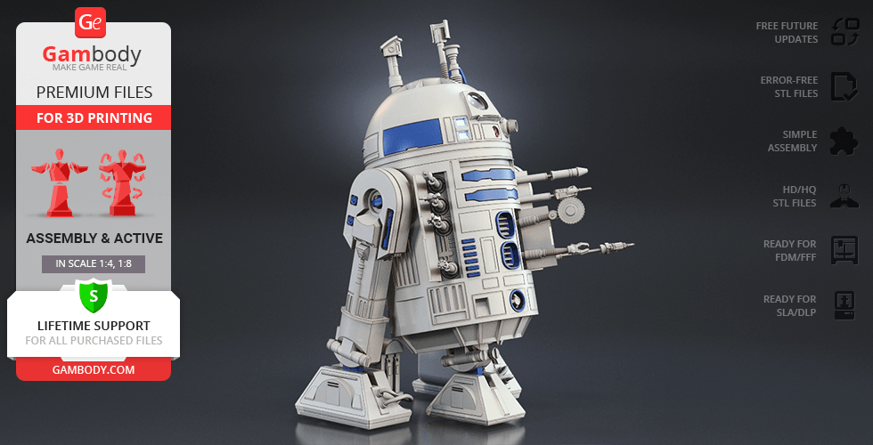
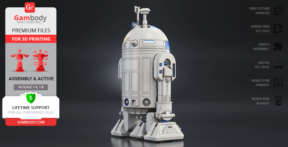
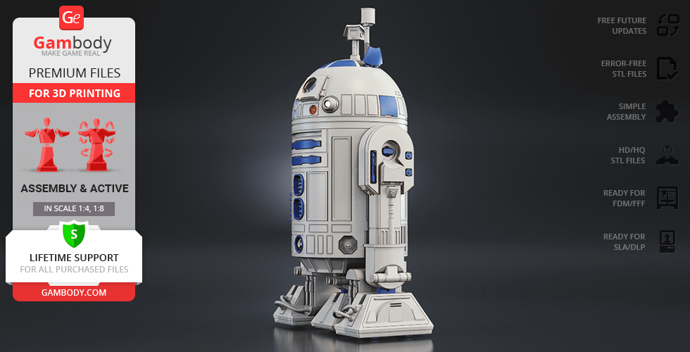
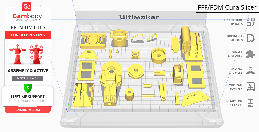
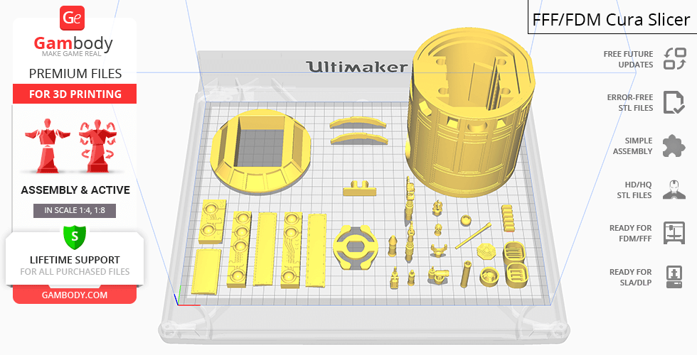
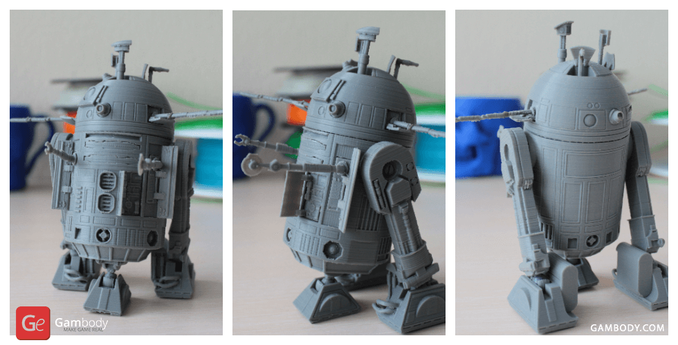
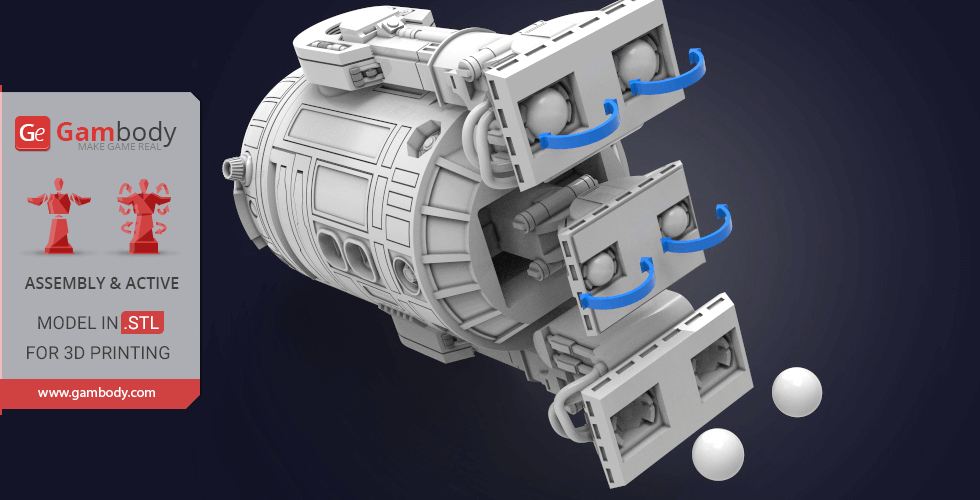
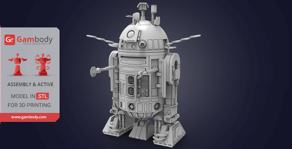
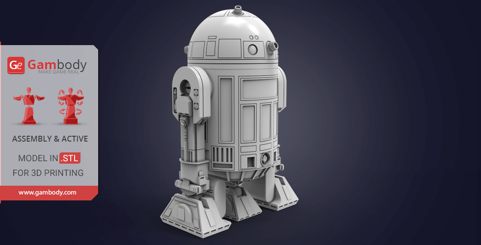
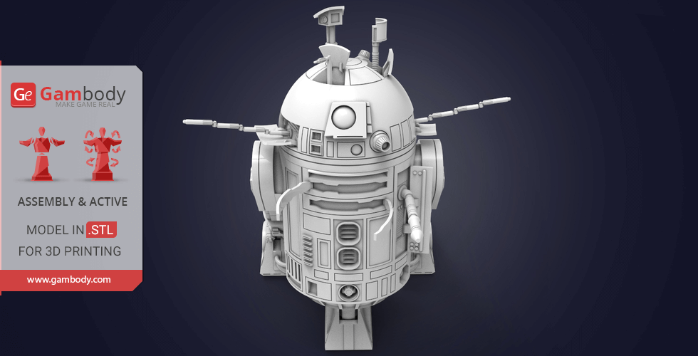
What is more, when preparing the model's update its level of exterior detailandaccuracy were significantly enhanced. Also, for you to receive the cleanest 3D printed result possible and to minimize the amount of filament needed for generated support the R2-D2 model was divided into many assembly parts, e.g. its domed head, acoustic signalers, various gadgets, feet, powerbus cables, radar eye, etc. are provided as separate STL files.
All assembly parts are provided in STL files in recommended positions that were worked out in order to ensure the smoothness of the details’ surfaces after printing and that the 3D printing beginners won't face difficulties when placing the parts on a build plate. When downloading any model's file you will also receive "Assembly Manual" for FFF/FDM 2.0 and DLP/SLA/SLS 2.0 versions in PDF format.
The model is saved in STL files, a format supported by most 3D printers. All STL files for 3D printing have been checked in Netfabb and no errors were shown.
The model's scale was calculated from the actual height of R2-D2 Droid that is 1090 mm. The 3D printing model's chosen scale is 1:4 for the FFF/FDM version and 1:8 for the DLP/SLA/SLS version.
VERSIONS' SPECIFICATIONS
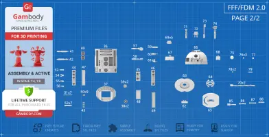
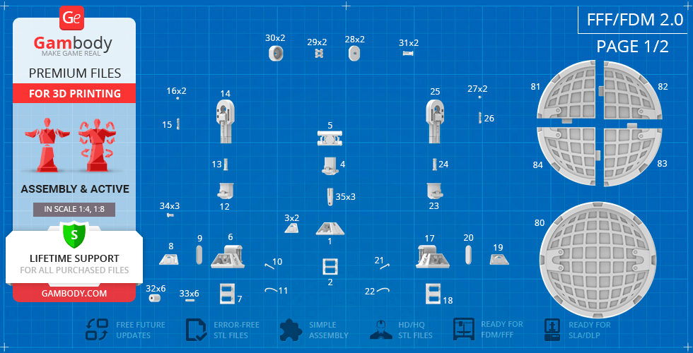
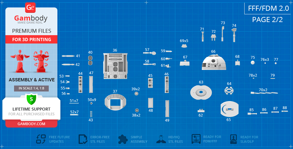
FFF/FDM 2.0 version features:
- Contains 98 parts;
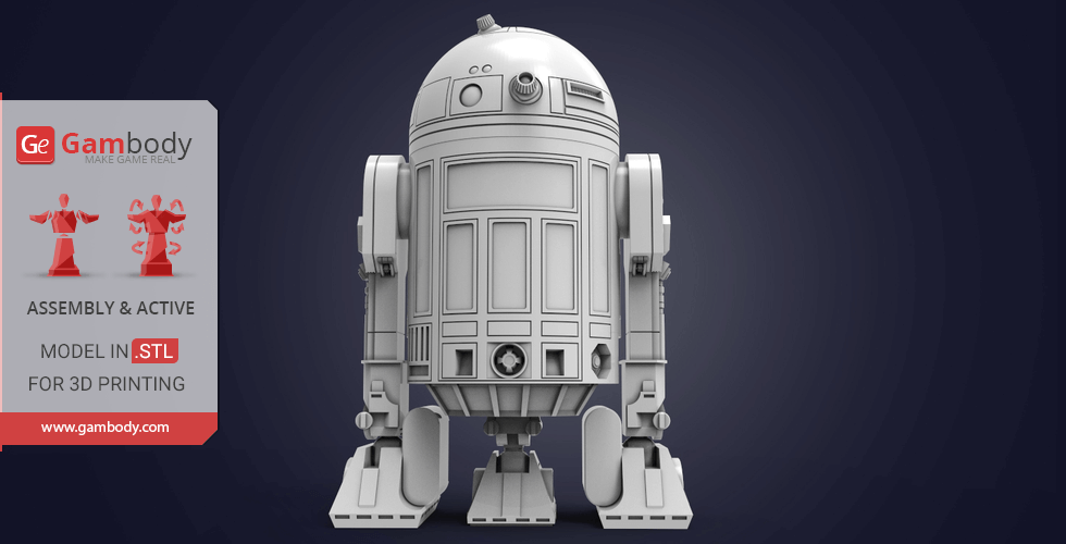
- A printed model is 276 mm tall, 302 mm wide, 302 mm deep;
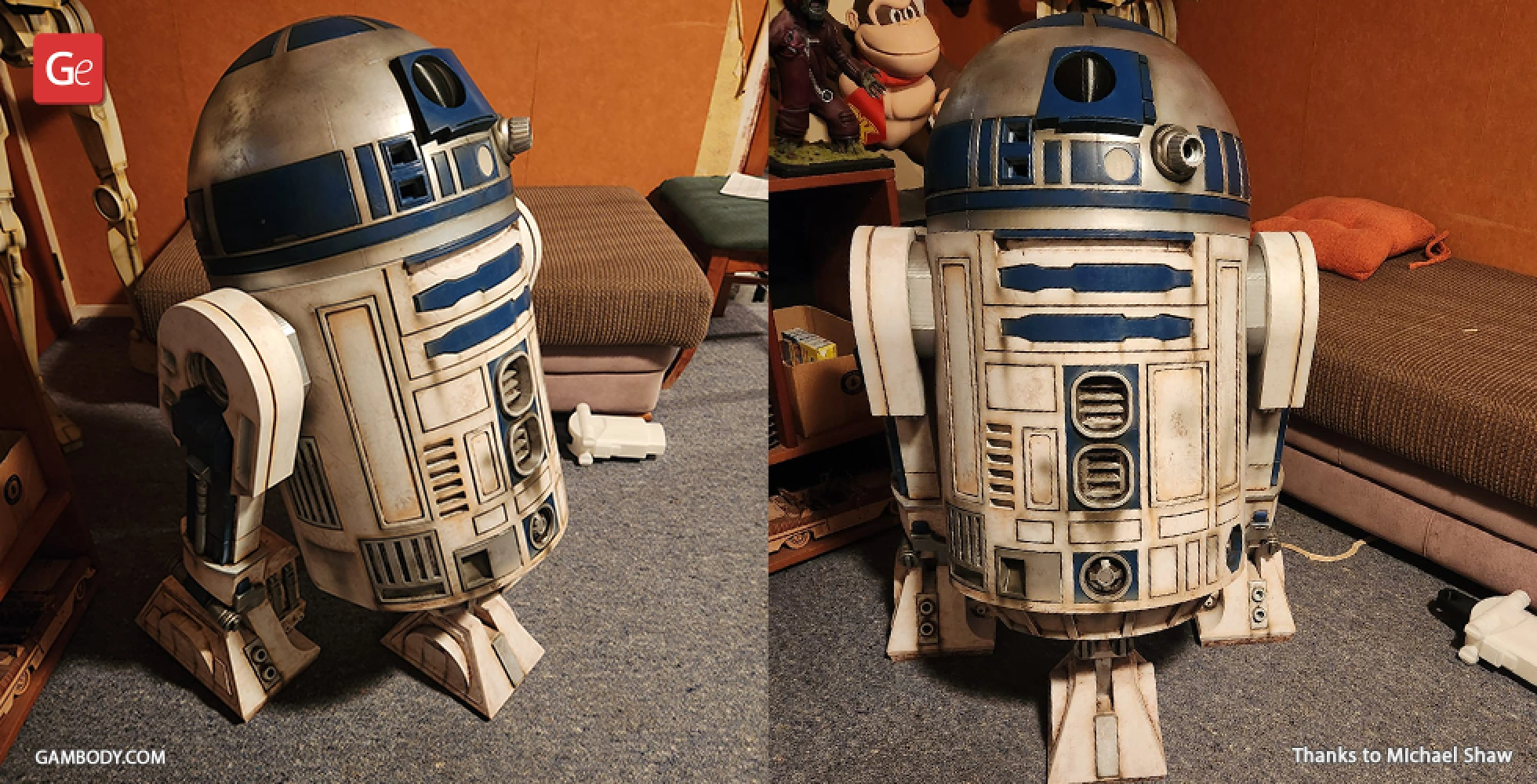
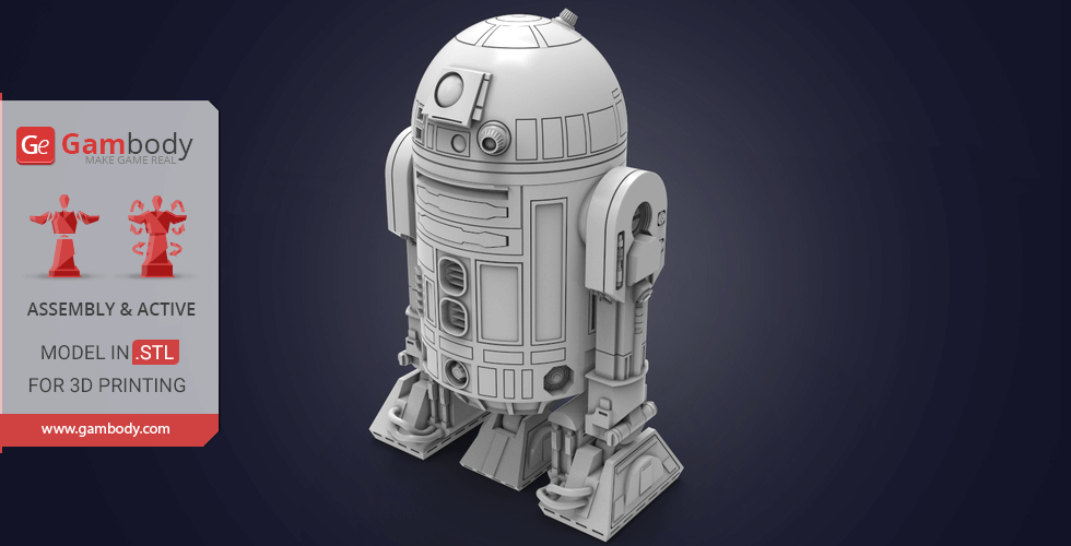
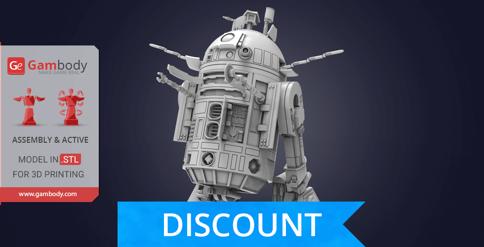
- The updated version of the model with a significantly enhanced level of exterior detail and authenticity, new articulated elements, fully updated cutting, and new scale;
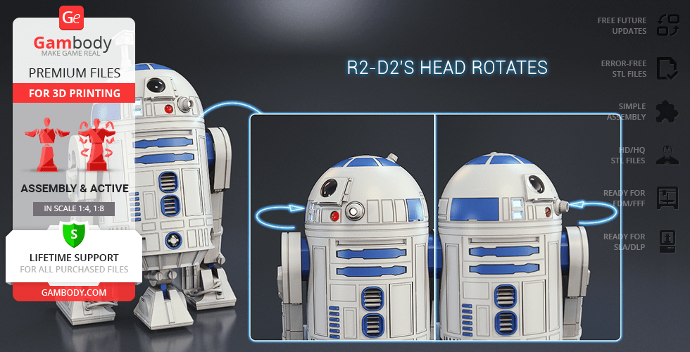
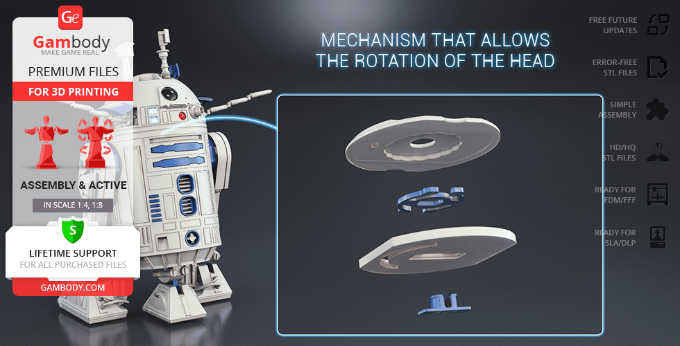
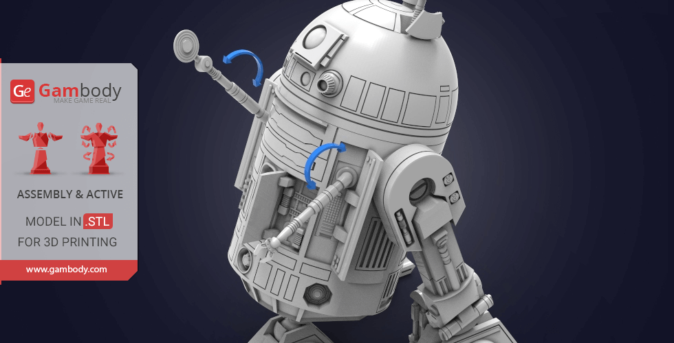
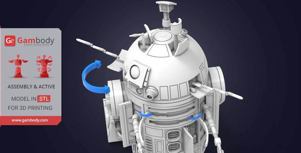
- R2-D2's head rotates via a ratchet mechanism;
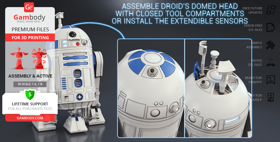
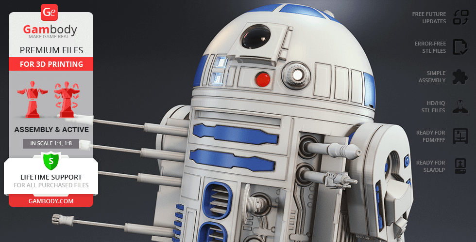
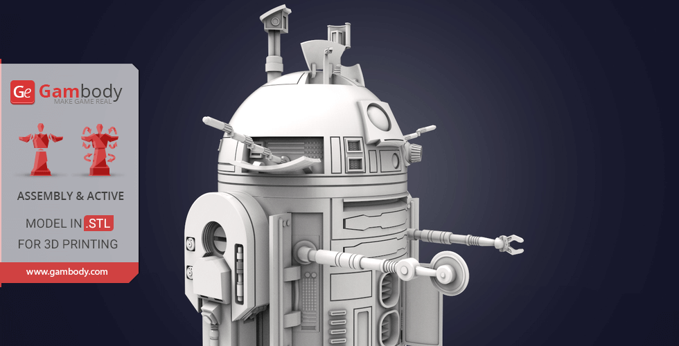
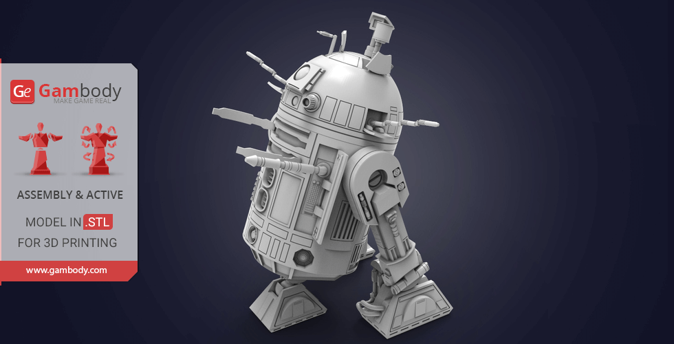
- Assemble droid’s domed head with closed tool compartments (there are five covers) or install the extendible sensors - there is a periscope, life form scanner, and hidden lightsaber compartment with ejector;
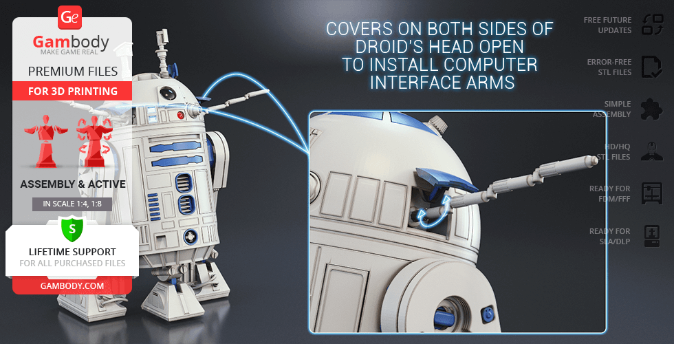
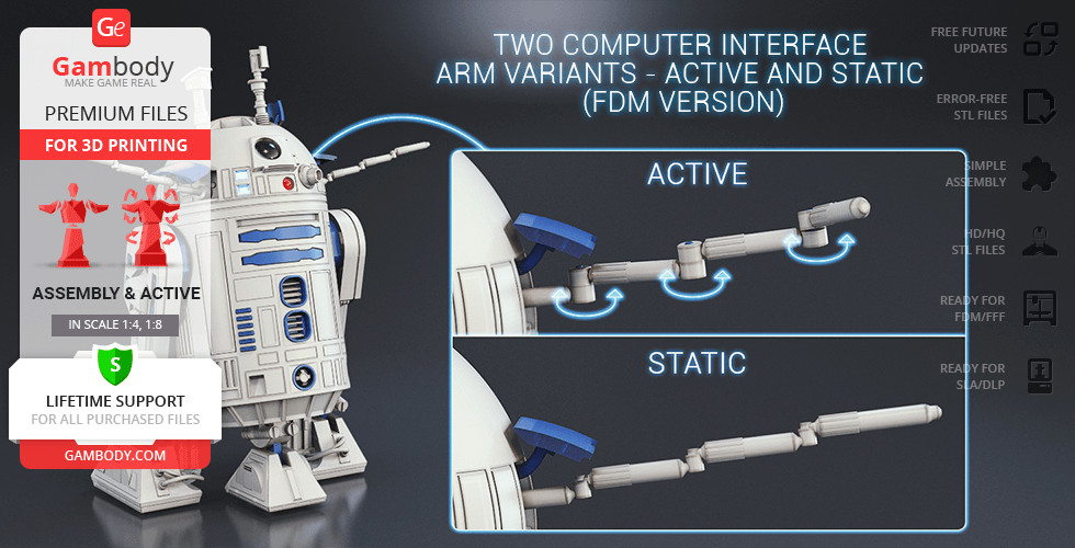
- Covers on both sides of droid’s head open to install computer interface arms. There are two computer interface arm variants - active and static;
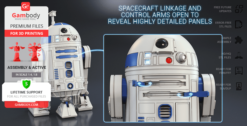
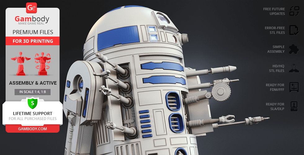
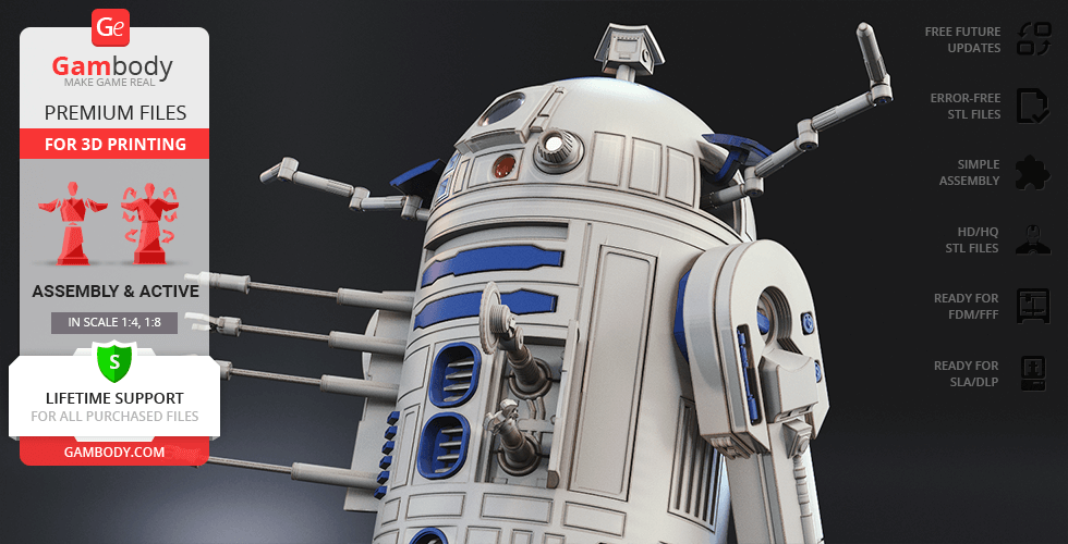
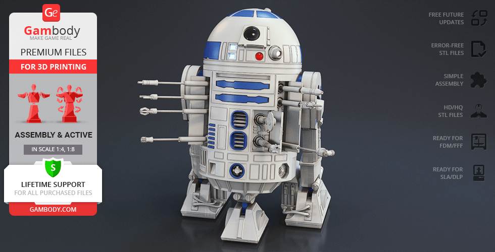
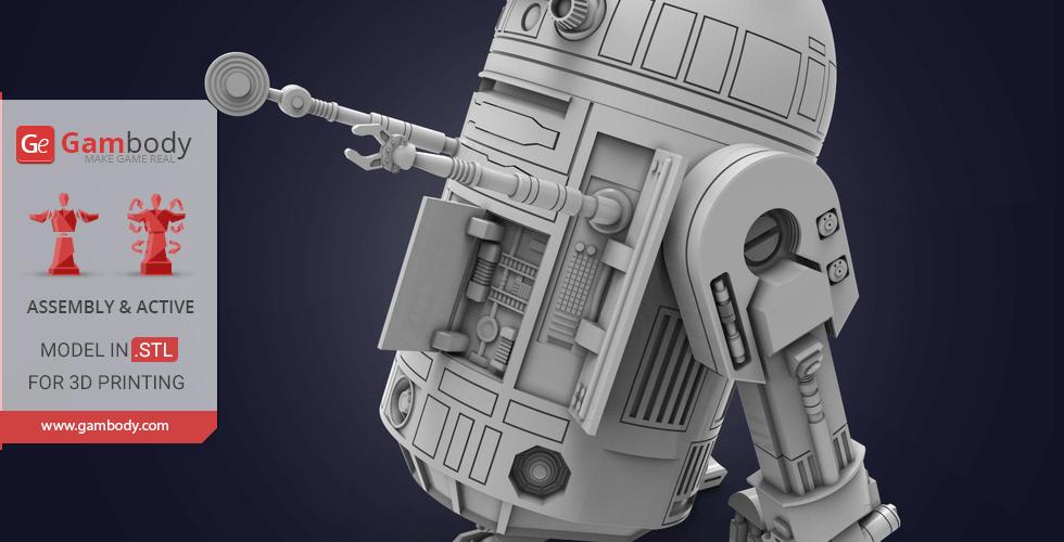
- Spacecraft linkage and control arms open to reveal highly detailed panels;
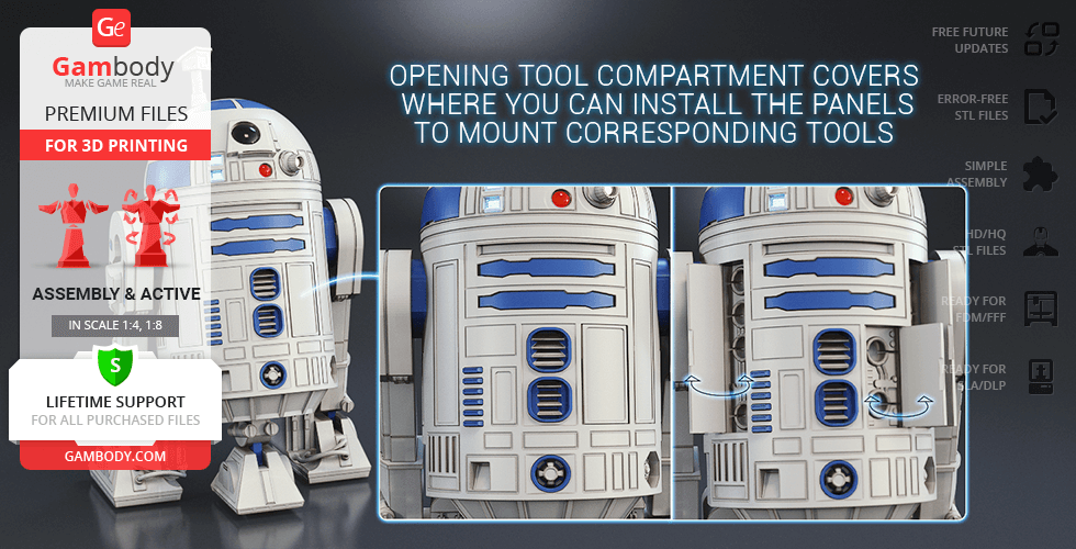
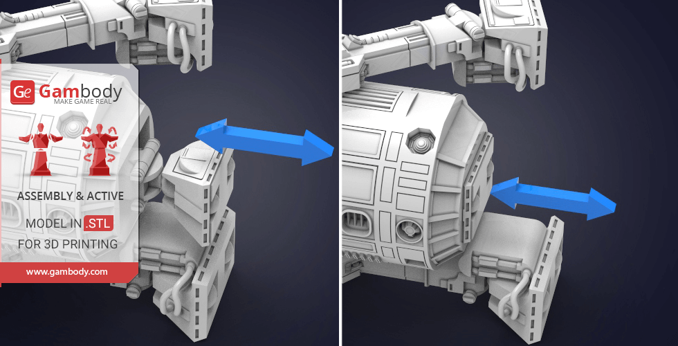
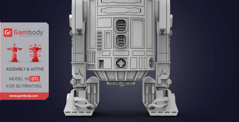
- There are opening tool compartment covers on the droid's body where you can install the panelsto mount corresponding tools;
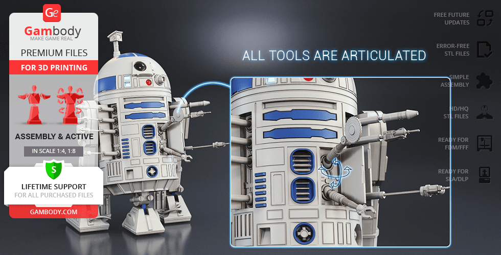
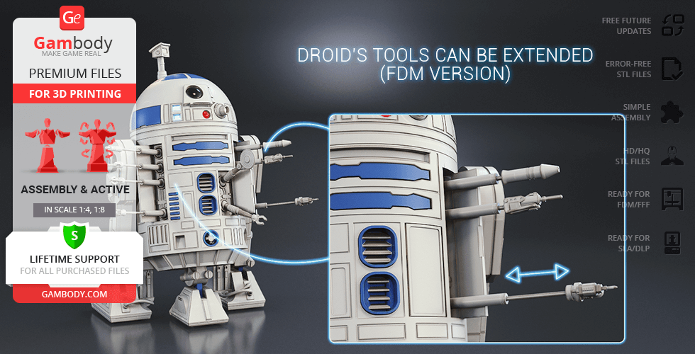
- All droid's tools are articulated and most tools can be extended via the telescoping inner tube (except for circular saw and front utility arm);
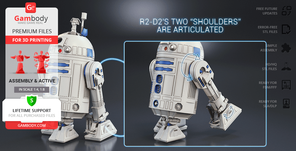
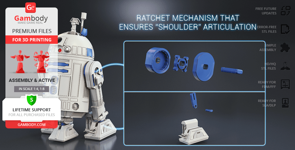
- R2-D2's two “shoulders” are articulated via a ratchet mechanism;
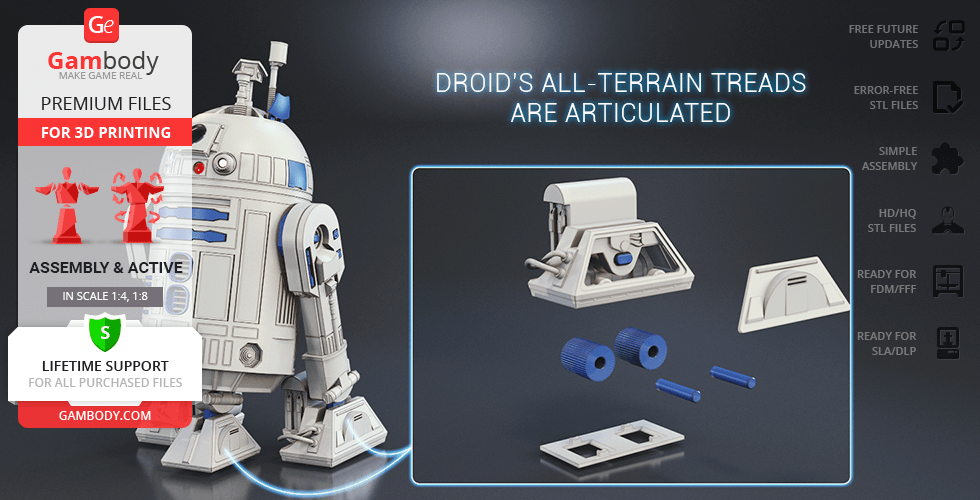
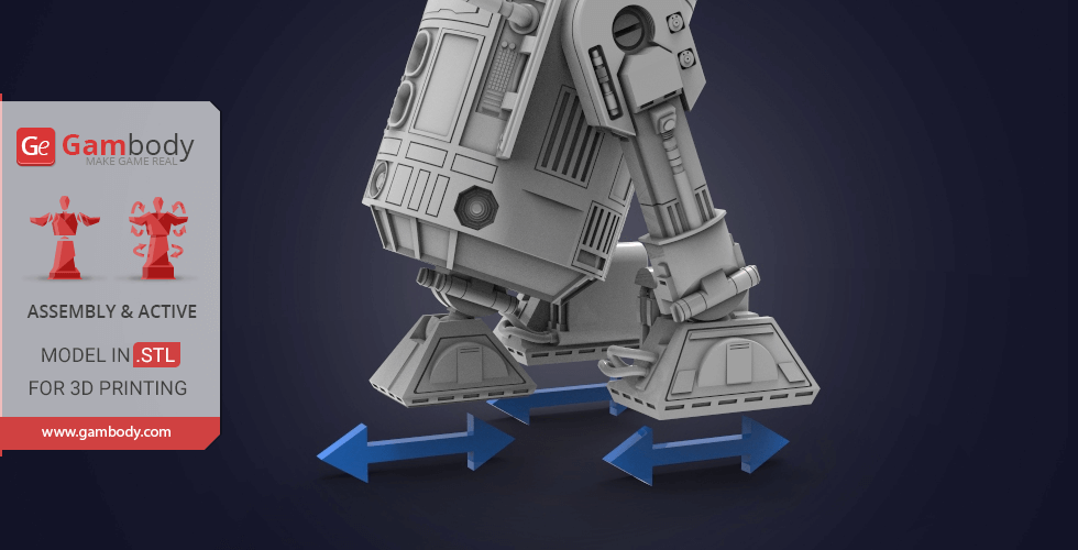
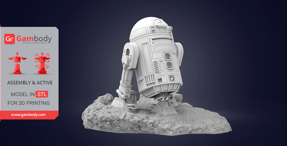
- Droid’s all-terrain treads are articulated and equipped with active wheels;
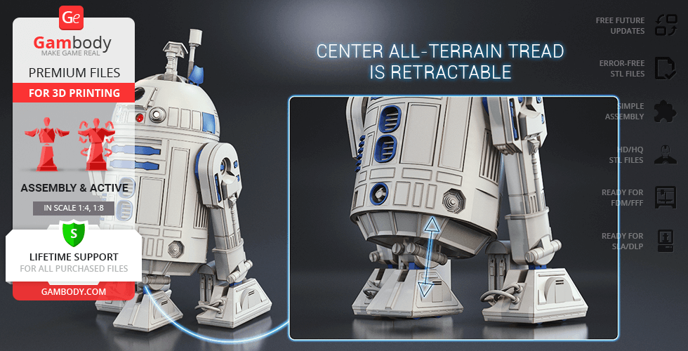
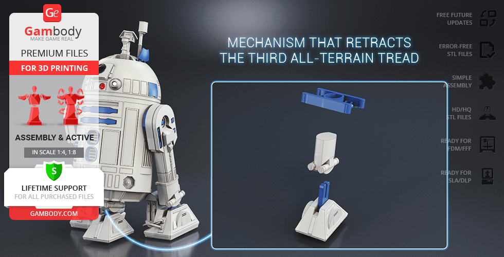
- Center all-terrain tread retracts with the help of a special mechanism;
- Separate leg parts available for printing in canonical colors using multicolor (AMS) technology
- The Droid’s "eyes" (holographic projector, primary photo receptor and radar eye, processor state indicator, logic function displays) are provided as separate assembly parts and can be printed with transparent filament;
- The tunnels throughout Droid’s hollow body allow to hide a battery inside the model and introduce LED wiring to light up the "eyes";
- The assembly of the active computer interface arm variant and the assembly of some compartment covers requires additional “pins”. These pins do not come in STL files but can be made out of short pieces of regular 1.75 PLA;
- Powerbus cables on both R2-D2 legs can be 3D printed or replaced with short pieces of real cables;
- It is highly recommended that you watch "Assembly video" in the photo preview section and read "Assembly Manual" in PDF before assembling the Droid;
- All parts are divided in such a way that you will print them with the smallest number of support structures.
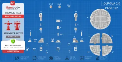
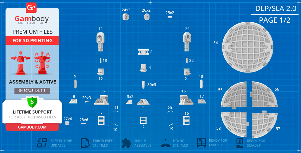
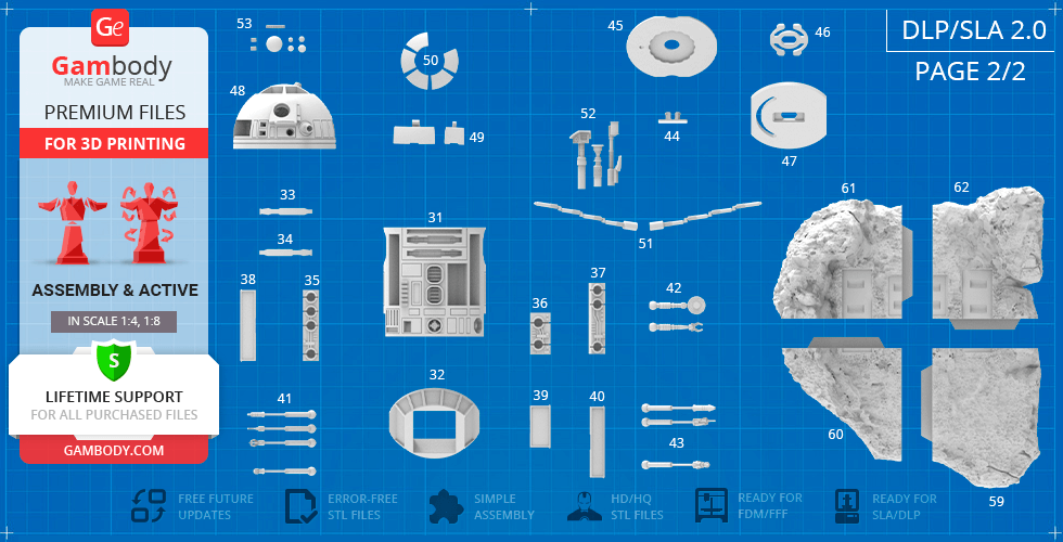
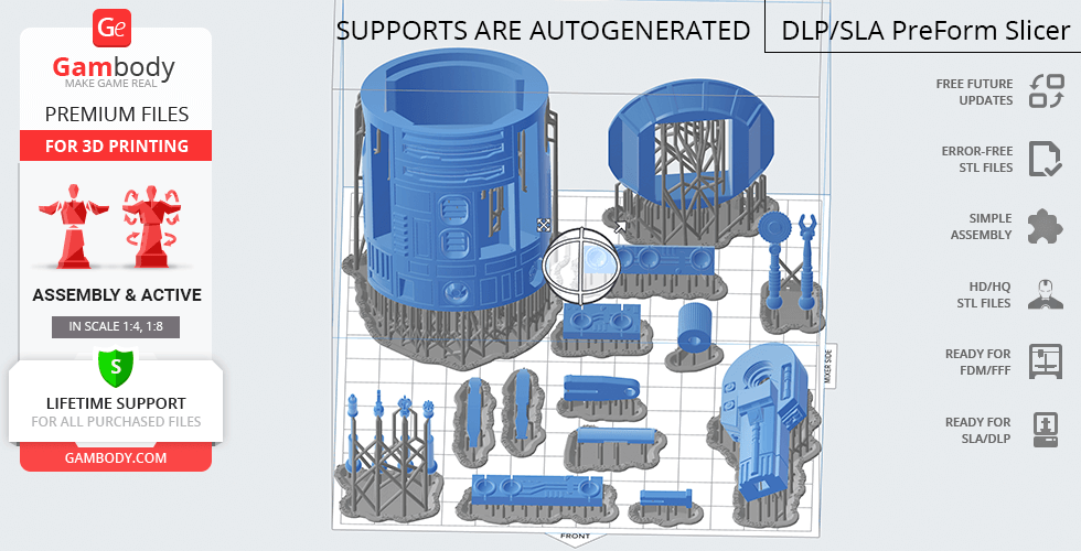
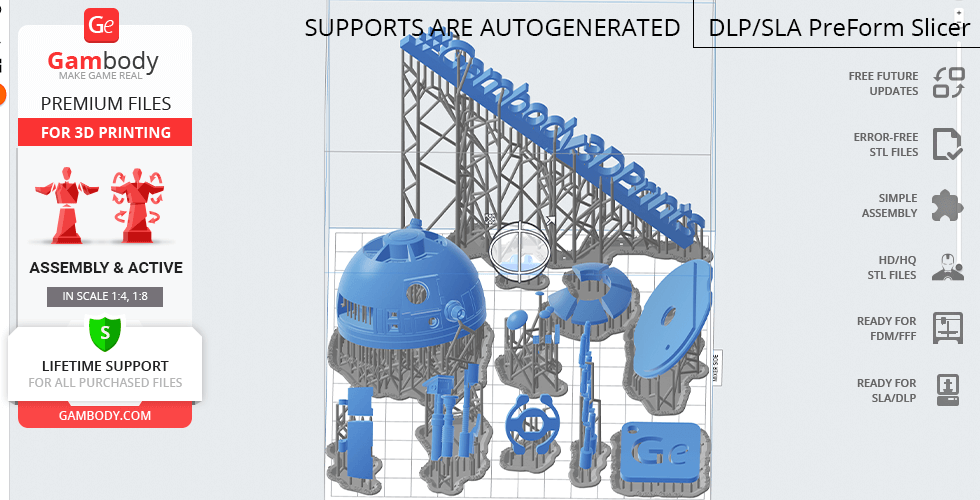
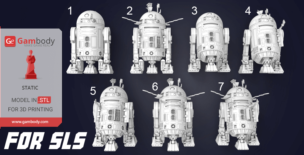
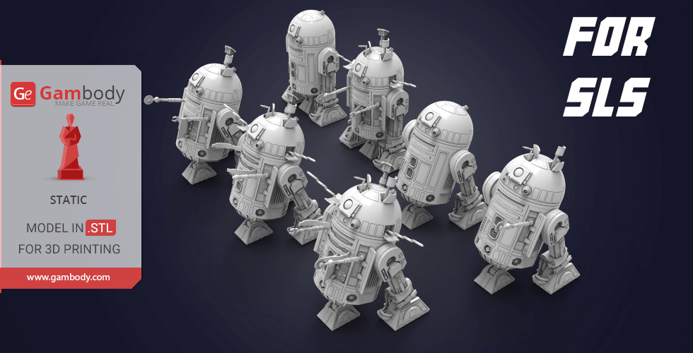
DLP/SLA/SLS 2.0 version features:
- Contains 62 parts;
- A printed model is 138 mm tall, 151 mm wide, 151 mm deep;
- The updated version of the model with a significantly enhanced level of exterior detail and authenticity, new articulated elements, fully updated cutting, and new scale;
- R2-D2's head rotates via a ratchet mechanism;
- Assemble droid’s domed head with closed tool compartments (there are five covers) or install the extendible sensors - there is a periscope, life form scanner, and hidden lightsaber compartment with ejector;
- Covers on both sides of droid’s head open to install computer interface arms;
- Spacecraft linkage and control arms open to reveal highly detailed panels;
- There are opening tool compartment covers on the droid's body where you can install the panelsto mount corresponding tools;
- All droid's tools are articulated;
- R2-D2's two “shoulders” are articulated via a simplified mechanism;
- Droid’s all-terrain treads are articulated and equipped with active wheels;
- Center all-terrain tread retracts with the help of a special mechanism;
- The Droid’s "eyes" (holographic projector, primary photo receptor and radar eye, processor state indicator, logic function displays) are provided as separate assembly parts and can be printed with transparent material;
- The tunnels throughout Droid’s hollow body allow to hide a battery inside the model and introduce LED wiring to light up the "eyes";
- Powerbus cables on both R2-D2 legs can be 3D printed or replaced with short pieces of real cables;
- The assembly of the active computer interface arm variant and the assembly of some compartment covers requires additional “pins”. These pins do not come in STL files but can be made out of short pieces of regular paperclip;
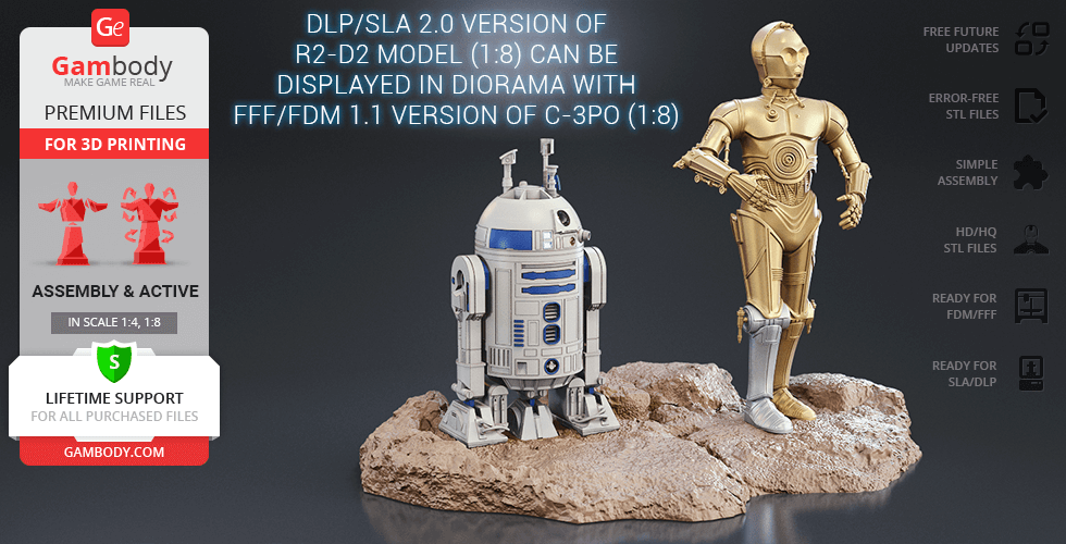
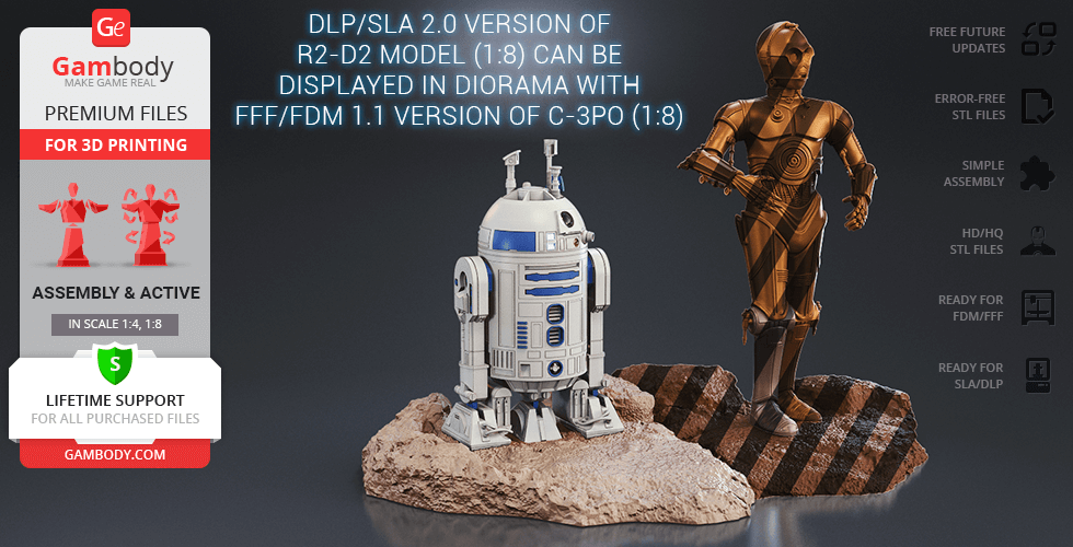
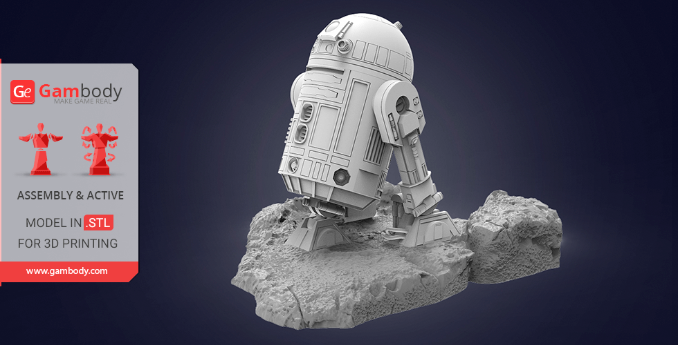
- DLP/SLA/SLS 2.0 version of R2-D2 model (1:8 scale) can be displayed in diorama with FFF/FDM 1.1 version of C-3PO figurine (1:8 scale);
- It is highly recommended that you watch "Assembly video" in the photo preview section and read "Assembly Manual" in PDF before assembling the Droid;- All parts are divided in such a way to fit the build plates and to ensure that support structures are generated where needed.
FFF/FDM 1.0 version features:
- Contains 49 parts;
- A printed model is 132 mm tall, 87 mm wide, 62 mm deep;
- The initial version of the R2-D2 3D printing model released in 2017;
- The scale of the model is 1:8.
DLP/SLA/SLS 1.0 version features:
- Contains 8 parts;
- A printed model is 70 mm tall, 47 mm wide, 33 mm deep;
- The initial version of the R2-D2 3D printing model released in 2017;
- The scale of the model is 1:16.
You can get the model of R2-D2 for 3D Printing immediately after the purchase! Just click the green Buy button in the top-right corner of the model’s page. You can pay with PayPal or your credit card.
Watch the tutorial on how to assemble R2-D2 3D Printing Model at Gambody YouTube channel.
Also, you may like C-3PO3D Printing Figurine, other Space War Online 3D Printing Figurines, as well as other Droid 3D Printing Models.
_______
FAQ:
Average customer rating (34 reviews)
4.2
Ratings breakdown
Click a star rating to filter reviews
Overall experience
Level of detail in the model
4.2
Model cut quality and assembly guide
4.2
Clarity and accuracy of the model page
4.2
Level of detail in the model
5
Model cut quality and assembly guide
5
Clarity and accuracy of the model page
5
Level of detail in the model
4
Model cut quality and assembly guide
4
Clarity and accuracy of the model page
4
Level of detail in the model
5
Model cut quality and assembly guide
5
Clarity and accuracy of the model page
5
Level of detail in the model
4
Model cut quality and assembly guide
4
Clarity and accuracy of the model page
4
Level of detail in the model
5
Model cut quality and assembly guide
5
Clarity and accuracy of the model page
5
Level of detail in the model
5
Model cut quality and assembly guide
5
Clarity and accuracy of the model page
5
Level of detail in the model
5
Model cut quality and assembly guide
5
Clarity and accuracy of the model page
5
Level of detail in the model
1
Model cut quality and assembly guide
1
Clarity and accuracy of the model page
1
Level of detail in the model
5
Model cut quality and assembly guide
5
Clarity and accuracy of the model page
5
Level of detail in the model
3
Model cut quality and assembly guide
3
Clarity and accuracy of the model page
3
Level of detail in the model
5
Model cut quality and assembly guide
5
Clarity and accuracy of the model page
5
Level of detail in the model
5
Model cut quality and assembly guide
5
Clarity and accuracy of the model page
5
Level of detail in the model
3
Model cut quality and assembly guide
3
Clarity and accuracy of the model page
3
Level of detail in the model
3
Model cut quality and assembly guide
3
Clarity and accuracy of the model page
3
Level of detail in the model
5
Model cut quality and assembly guide
5
Clarity and accuracy of the model page
5
Level of detail in the model
3
Model cut quality and assembly guide
3
Clarity and accuracy of the model page
3
Level of detail in the model
5
Model cut quality and assembly guide
5
Clarity and accuracy of the model page
5
Level of detail in the model
1
Model cut quality and assembly guide
1
Clarity and accuracy of the model page
1
Level of detail in the model
5
Model cut quality and assembly guide
5
Clarity and accuracy of the model page
5
Level of detail in the model
3
Model cut quality and assembly guide
3
Clarity and accuracy of the model page
3
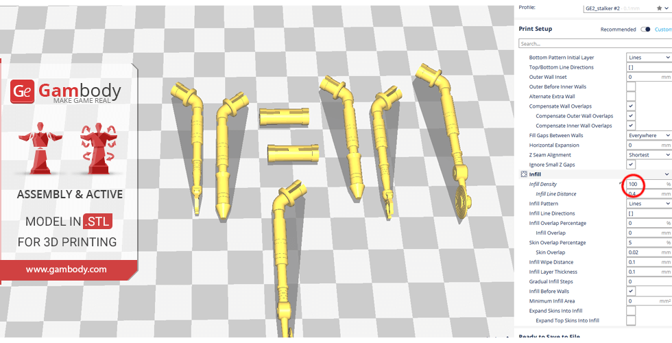
Below you'll find detailed slicing settings for Bambu Studio 2.0+, Orca Slicer 2.0+, UltiMaker Cura 5.0+, PrusaSlicer 2.0+, Slic3r 1.3+, Simplify3D 5.0+ to help you get the best results when printing this model. These settings are optimized specifically for this 3D model, but please note they may need slight adjustments depending on your printer or filament. When in doubt, refer to your printer's user manual.
To avoid printing issues and achieve the best quality, we highly recommend applying the following settings:
For better quality use 0.12 mm layer height, for fast printing use 0.2 mm layer height. For pins and the Ge connectors, use 0.2 layer height.
120-150% of your Layer Height
But you can paint the seam if you want.
You have to calibrate this parameter
You have to calibrate this parameter
You have to calibrate this parameter
For pins and power elements of the structure, such as the vehicle frame, use 3 loop
Disabled for vehicles and enabled for characters
For 0,2 Layer Height
The parameters in this tab vary greatly, it all depends on the quality of your printer. For example, if you have a classic Ender3, stick to the minimum parameters, but if you have a newer printer, for example Anycubic cobra 3 v2, you can select the maximum recommended values
Settings for advanced users, change these parameters only if you have sufficient 3D printing expertise
Enable this parameter if your model requires supports
We also recommend placing and removing supports manually in some places using special button
1-2 loops for more thick support
Top Z distance = 1-1.3 layer Height. If the supports are hard to remove, try increasing this setting by 0.1-0,4 mm
Bottom Z distance = 1-1.3 layer Height. If the supports are hard to remove, try increasing this setting by 0.1-0,4 mm
You have to calibrate this parameter which one is better for your filament
Increase this parameter if the supports are hard to remove from walls
For PLA and PETG filament types
5-8 mm is optional for small prints that have bad adhesion to the build plate
You have to calibrate this parameter
Read the description on your filament roll
Read the description on your filament roll and increase this parameter for fast printers
Read the description on your filament roll and increase this parameter for fast printers
For better quality use 0.12 mm layer height, for fast printing use 0.2 mm layer height. For pins and the Ge connectors, use 0.2 layer height.
120-150% of your Layer Height
But you can paint the seam if you want.
0.01-0.05 You have to calibrate this parameter
0.01-0.05 You have to calibrate this parameter
0.1-0.2 You have to calibrate this parameter
For pins and power elements of the structure, such as the vehicle frame, use 3 loop
Disabled for vehicles and ships, enabled for characters
For 0,2 Layer Height
For 0,2 Layer Height
The parameters in this tab vary greatly, it all depends on the quality of your printer. For example, if you have a classic Ender3, stick to the minimum parameters, but if you have a newer printer, for example, Anycubic Kobra 3 Or Bambulab A1, you can select the maximum recommended values.
Settings for advanced users, change these parameters only if you have sufficient 3D printing expertise
Enable this parameter if your model requires supports
We also recommend placing and removing supports manually in some places using special button
Top Z distance = 1-1.3 layer Height. If the supports are hard to remove, try increasing this setting by 0.1-0,4 mm
Bottom Z distance = 1-1.3 layer Height. If the supports are hard to remove, try increasing this setting by 0.1-0,4 mm
Increase this parameter if the supports are hard to remove from walls
For PLA and PETG filament types
5-8 mm is optional for small prints that have bad adhesion to the build plate
Read the description on your filament roll
Read the description on your filament roll and increase this parameter for fast printers
You have to calibrate this parameter
Read the description on your filament roll and increase this parameter for fast printers
Read the description on your filament roll
This field is filled in according to your printer specifications when you add it to the slicer.
You can add custom G-code here for the start and end of the print. However, be careful - this is for advanced users only!
You have to calibrate your printer using Ge retraction test models
Retraction Length: For direct-drive setups use 0.5 mm to 2.5 mm; for Bowden extruders use 5 to 7 mm
This is how fast the filament is pulled back—40-60 mm/s for direct drive and 30-50 mm/s for Bowden setups.
You have to calibrate this parameter: Reduce it until the printer starts to hit the parts with the nozzle during printing, then increase it by 0.2.
For better quality use 0.12 mm layer height, for fast printing use 0.2 mm layer height. For pins and the Ge connectors, use 0.2 layer height.
120-150% of your Layer Height
To increase the strength of the print parts, use wall line count: 3
For pins and connectors use 50% Infill
These parameters are for standard PLA plastic. If you are using a different type of plastic, check the printing temperature recommended by the manufacturer. Also, read the description on your filament spool. For fast printers, add +30 °C to the current parameters.
The parameters in this tab vary greatly, it all depends on the quality of your printer. For example, if you have a classic Ender3, stick to the minimum parameters, but if you have a newer printer, for example Anycubic cobra 3 v3, you can select the maximum recommended values
Settings for advanced users, change these parameters only if you have sufficient 3D printing expertise.
You need to calibrate this parameter using Gambody test models. These values are average values for a Direct Drive extruder; for a Bowden extruder, the values should be increased.
You need to calibrate this parameter using Gambody test models. These values are average values for a Direct Drive extruder; for a Bowden extruder, the values should be increased.
Use this value other than 0 if your nozzle catches on the internal infill during travel moves. Try to keep this value as low as possible in height.
Use normal supports to support large, straight surfaces (most mechanical or technical parts).
You have to calibrate this parameter according to the capabilities of your printer and your filament, using a Gambody test models.
Use 1 instead of 0 if your supports are thin and tall. They will be harder to remove, but much stronger.
Top Z distance = 1-1.3 layer Height. If the supports are hard to remove, try increasing this setting by 0.1-0,4 mm
Increase this parameter if the supports are hard to remove from walls
Use tree supports to support complex objects, such as characters.
You have to calibrate this parameter according to the capabilities of your printer and your filament, using a Gambody test models.
Top Z distance = 1-1.3 layer Height. If the supports are hard to remove, try increasing this setting by 0.1-0,4 mm
Increase this parameter if the supports are hard to remove from walls
Use a skirt for all parts when printing on outdated printers.
Use a brim when printing thin but tall parts, as well as parts with a small bed adhesion area.
For better quality use 0.12 mm layer height, for fast printing use 0.2 mm layer height. For pins and the Ge connectors, use 0.2 layer height.
120-150% of your Layer Height
for 0.2 Layer Height
But you can paint the seam if you want.
(for PLA and PETG)
(5-8 mm is optional for small prints that have bad adhesion to the build plate)
Enable this parameter if your model requires supports
(45-50 degree)You have to calibrate this parameter according to the capabilities of your printer
and your filament, using a Gambody test models.
Top contact Z distance = 1-1.3 layer Height. If the supports are hard to remove, try
increasing this setting by 0.1-0,4 mm
Top contact Z distance = 1-1.3 layer Height. If the supports are hard to remove, try
increasing this setting by 0.1-0,4 mm
Increase this parameter if the supports are hard to remove from walls
The parameters in this tab vary greatly, it all depends on the quality of your printer. For example, if you have a classic Ender3, stick to the minimum parameters, but if you have a newer printer, for example Anycubic cobra 3 v3, you can select the maximum recommended values
Settings for advanced users, change these parameters only if you have sufficient 3D printing expertise. Use the minimum value for outdated printers without acceleration calibration, and the maximum value for modern printers if you need it.
These settings only work for 3D printers with multiple extruders
You can try setting all parameters in this section, except the First layer, to values between 0.75% of your nozzle diameter and 1.25% of your nozzle diameter. Adjusting them will help you work out the optimal parameters for the best quality for your print. As for the First layer, you can set it to 150% of the diameter of your nozzle for better adhesion to the build plate (for a nozzle with a diameter of 0.4 mm, the First layer extrusion width can be from 0.3 mm to 0.5 mm)
For better printing quality you have to calibrate this parameter using Gambody test model.
Check your filament manufacturer's temperature recommendations on the spool.
Cooling parameters depends on the material you use for printing.
*for PLA
For better quality use 0.12 mm layer height, for fast printing use 0.2 mm layer height. For pins and the Ge connectors, use 0.2 layer height.
120-150% of your Layer Height
For 0.12 Layer Height
For 0.12 Layer Height
For pins and connectors use 50% Infill
Use skirt for outdated 3d printers
(5-8 mm is optional for small prints that have bad adhesion to the build plate)
Enable this parameter if your model requires supports
(45-60 degree)You have to calibrate this parameter according to the capabilities of your printer and your filament, using a Gambody test models
Contact Z distance = 1-1.3 layer Height. If the supports are hard to remove, try increasing this setting by 0.1-0,4 mm
The parameters in this tab vary greatly, it all depends on the quality of your printer. For example, if you have a classic Ender3, stick to the minimum parameters, but if you have a newer printer, for example Anycubic cobra 3 v3, you can select the maximum recommended values
Settings for advanced users, change these parameters only if you have sufficient 3D printing expertise. Use the minimum value for outdated printers without acceleration calibration, and the maximum value for modern printers if you need it.
You have to calibrate this parameter from 0.9 to 1.1 according to the capabilities of your printer and your filament, using a Gambody test models.
Check your filament manufacturer's temperature recommendations on the spool.
Cooling parameters depends on the material you use for printing.
Calibrate this value if you need to reduce or improve the adhesion between the plastic and the heat bed
Your current nozzle diameter
You need to calibrate this parameter using Gambody test models. These values are average values for a Direct Drive extruder; for a Bowden extruder, the values should be increased.
Your current nozzle diameter
You have to calibrate this parameter using Gambody test models.
You need to calibrate this parameter using Gambody test models. These values are average values for a Direct Drive extruder; for a Bowden extruder, the values should be increased.
For better quality use 0.12 mm layer height, for fast printing use 0.2 mm layer height. For pins and the Ge connectors, use 0.2 layer height.
For 0,2 Layer Height
For 0,2 Layer Height
To increase the strength of the print parts, use Outline Perimeters: 3
You can enable this parameter to print rounded or spherical models, as well as character models.
Use this option only if your parts are too tight. but better calibrate your printer extrusion
Use this option only if your parts are too tight. but better calibrate your printer extrusion
Use 2 and more if you want to create skirt instead brim
1-2 for skirt and 10-20 for brim
Use for wipe nozzle if you need
Use For ABS filament
For pins and connectors use 50% Infill
Top Z distance = 1-1.3 layer Height. If the supports are hard to remove, try increasing this setting by 0.1-0,4 mm
Calibrate your filament and detect optimal temperature for it
Average temperature for PLA filament
The parameters in this tab vary greatly, it all depends on the quality of your printer. For example, if you have a classic Ender3, stick to the minimum parameters, but if you have a newer printer, for example Anycubic cobra 3 v3, you can select the maximum recommended values
Settings for advanced users, change these parameters only if you have sufficient 3D printing expertise.