


Files
3D model format
Stereolithography (.stl)
Total files
Slicer settings
Mesh error check
Netfabb
Support
Lifetime support from Gambody team
Update requests
Available to verified buyers
Model complexity
Standard: balanced printing difficulty and moderate part count with assembly steps.
Model versions
FFF/FDM
Assembly method
Connectors, Glue
Features
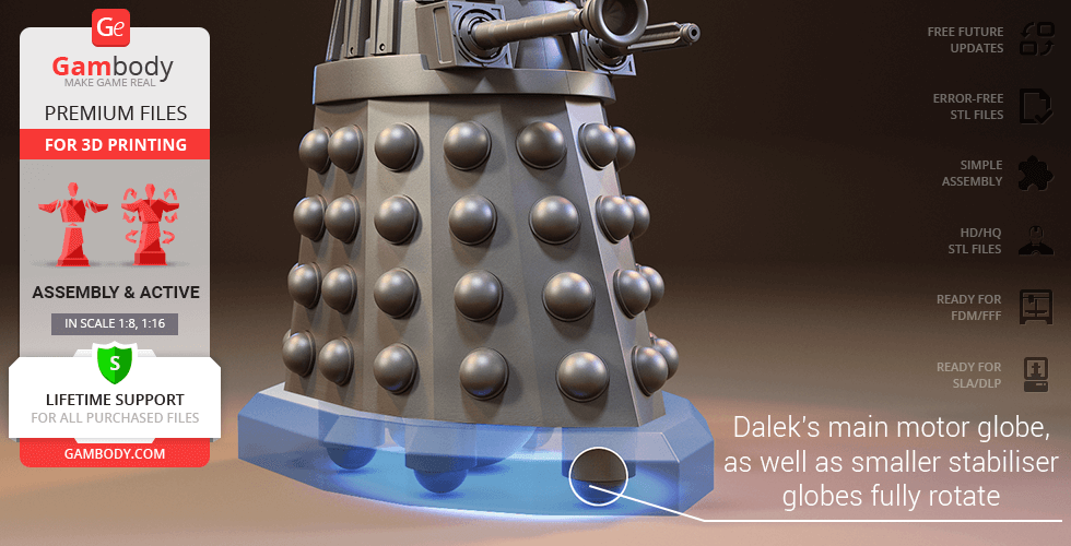
- Dalek’s main motor globe, as well as smaller stabilizer globes fully rotate to propel the Dalek in any direction (similar to a computer mouse ball);
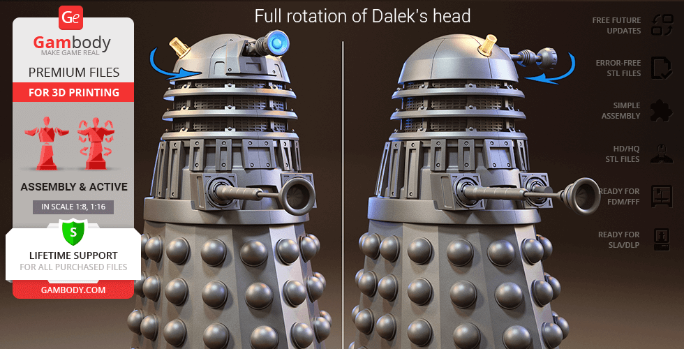
- Dalek's dome (head) revolves on its axis;
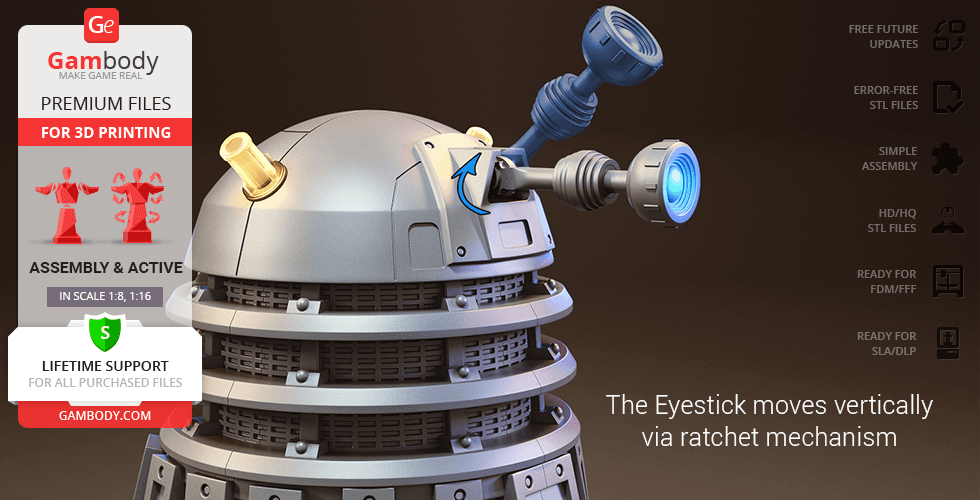
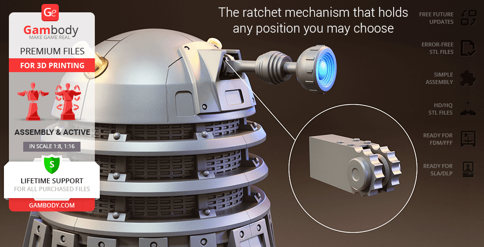
- The Eyestick moves vertically via a ratchet mechanism;
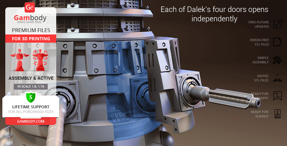
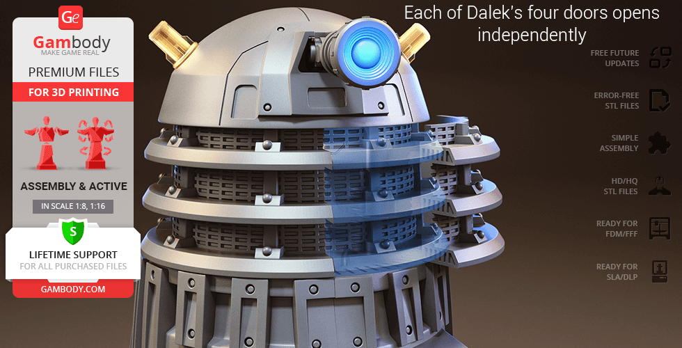
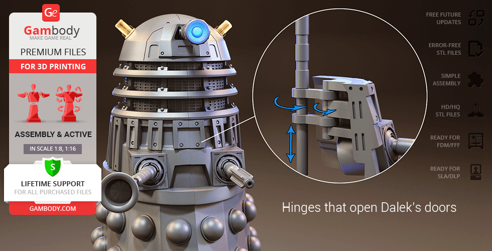
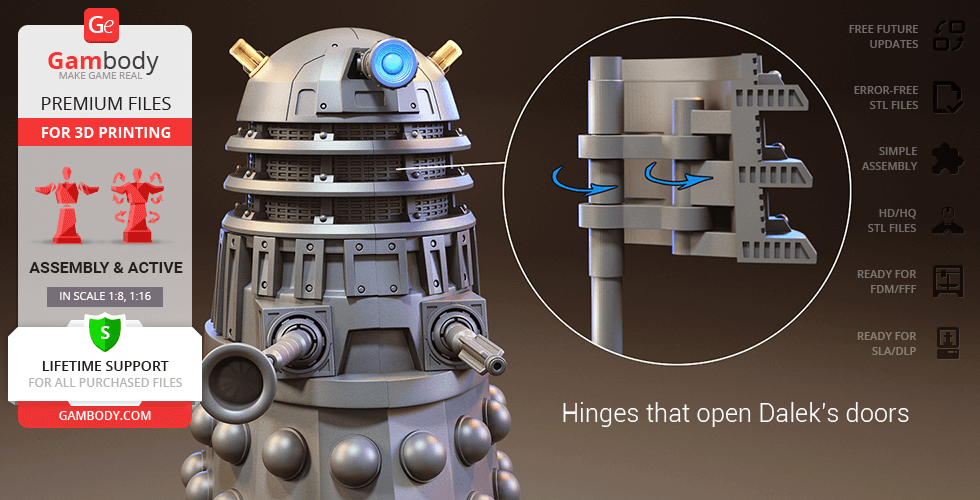
- Each of Dalek’s four doors opens independently with the help of a set of hinges; bottom doors can also be slightly lowered;
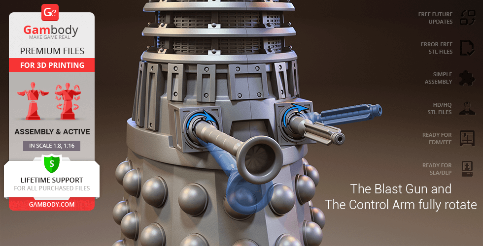
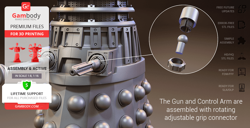
- The Blast Gun and Control Arm are assembled with an adjustable grip connector that can fully rotate;
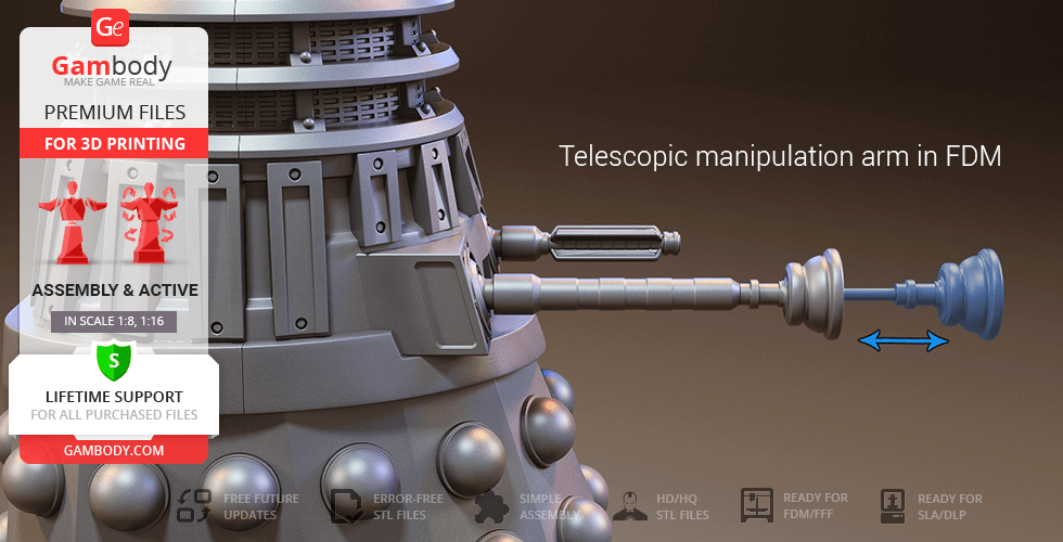
- The Control Arm is telescopic;
- The “light bulbs” (the Luminosity Dischargers) on the cyborg's dome are provided separately and can be printed with the transparent filament;
- Decorative wires inside Dalek's dome do not come in STL files but can be made out of short pieces of regular 1.75 PLA;
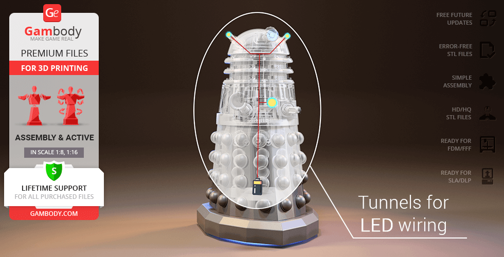
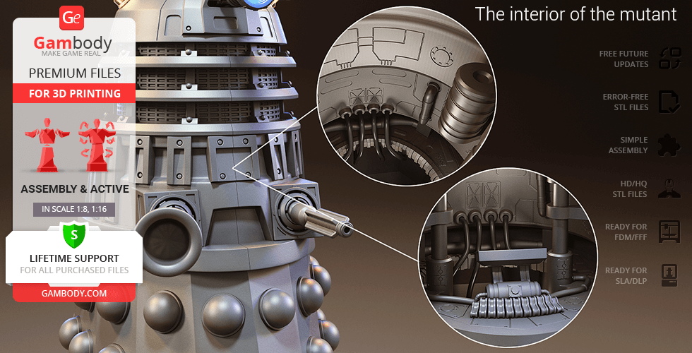
- Tunnels throughout the robot’s hollow body are provided for LED wiring to light up the highly-detailed interior, as well as the “light bulbs”;
DLP/SLA
Assembly method
Glue
Features
- Dalek’s main motor globe, as well as smaller stabilizer globes fully rotate to propel the Dalek in any direction (similar to a computer mouse ball);
- Dalek's dome (head) revolves on its axis, while the Eyestick moves vertically;
- Each of Dalek’s four doors opens independently with the help of a set of hinges; bottom doors can also be slightly lowered;
- The Blast Gun and Control Arm can fully rotate;
- Tunnels throughout the robot’s hollow body are provided for LED wiring to light up the highly-detailed interior, as well as the “light bulbs”
Additional details
Part of diorama
No
Special pack included
No
You will get instant access to the STL files of Dalek 3D Printing Model | Assembly + Action after completing your purchase. Simply add the model to your cart and check out using PayPal, credit or debit card, Apple Pay, Google Pay, Alipay, or other available payment methods.
Watch the assembly video for Dalek 3D Printing Model | Assembly + Action, and explore more tutorials, behind-the-scenes content, 3D printing timelapses, and painting guides on the official Gambody YouTube channel.
This 3D Model consists of files in StereoLithography (.Stl) format that is optimized for 3D printing.
Before printing the files, we strongly recommend reading the PRINTING DETAILS section.
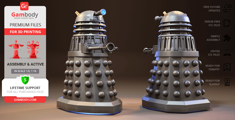
Dalek 3D Printing Model comes in 2 versions for FFF/FDM and DLP/SLA/SLS 3D printers. STL files of both versions are available for download after the purchase.
Detailed information about this 3D printing model is available in the DESCRIPTION section.
Before printing, take a look at Printing Details for recommended settings and tips to achieve better results.
ABOUT THIS 3D MODEL
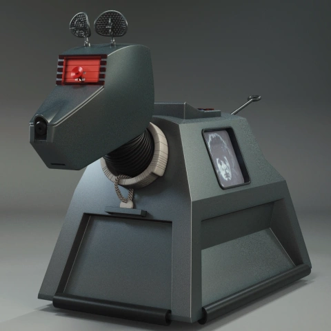
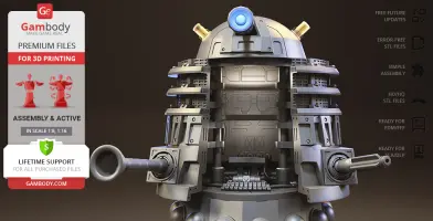
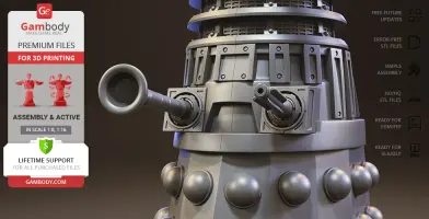
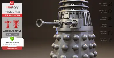
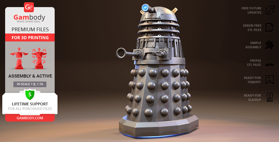
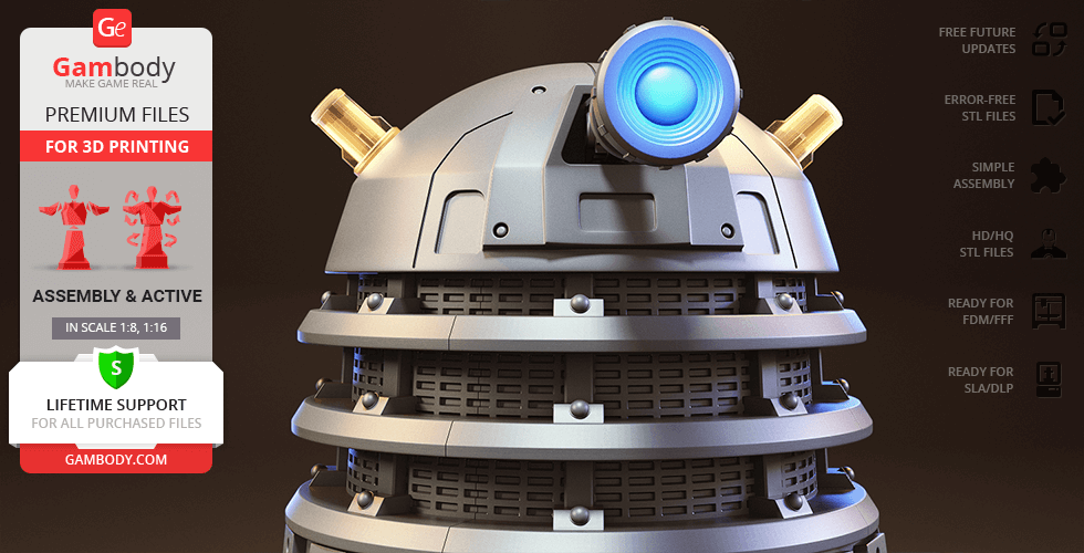
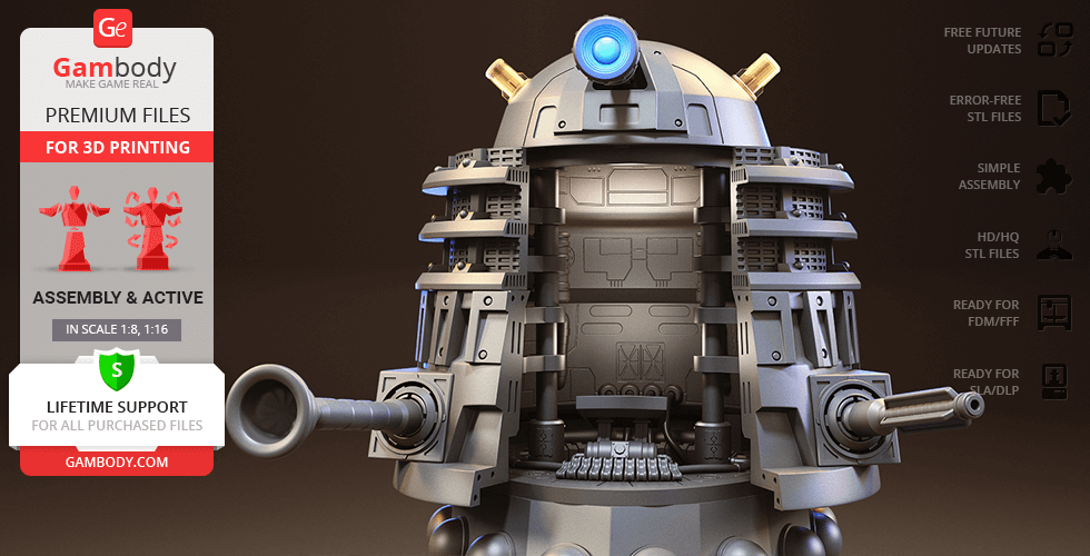
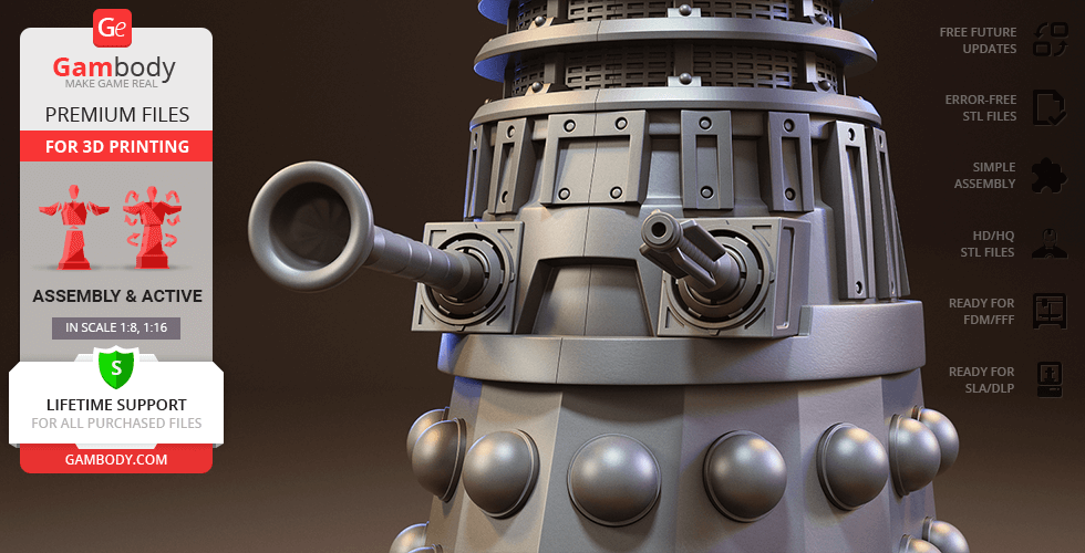
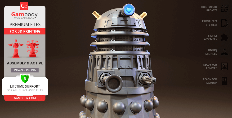
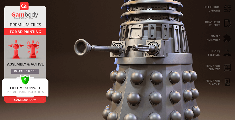
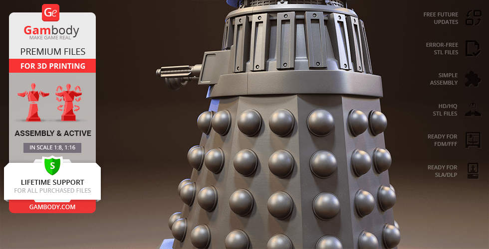
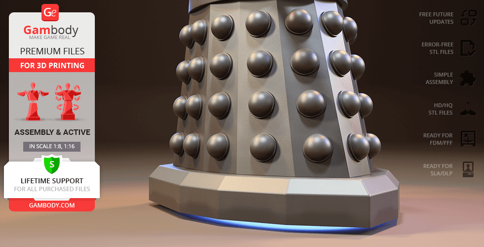
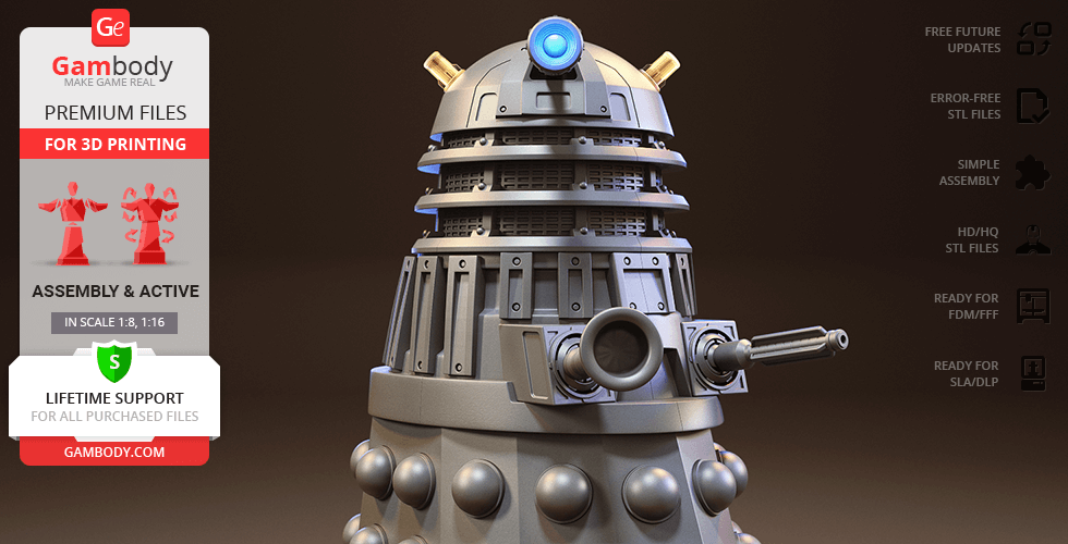
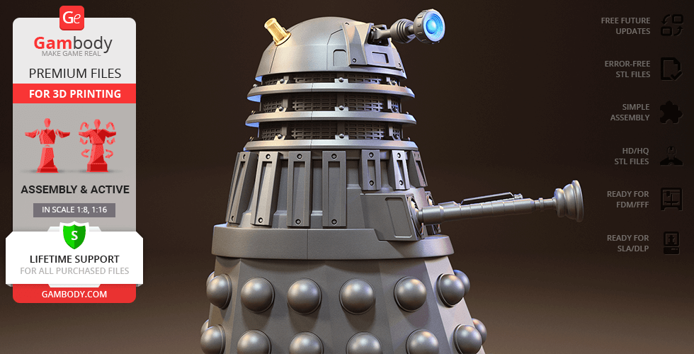
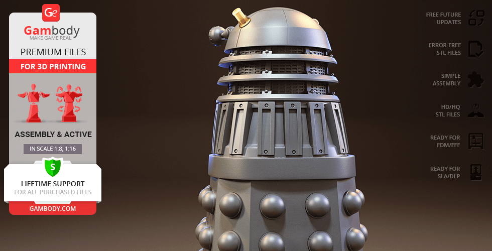
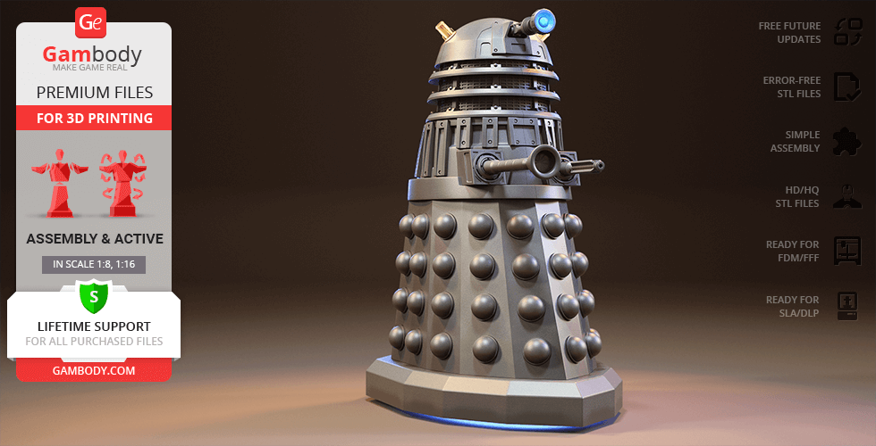
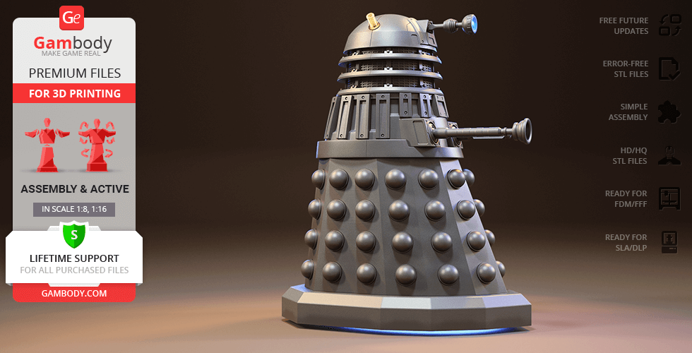
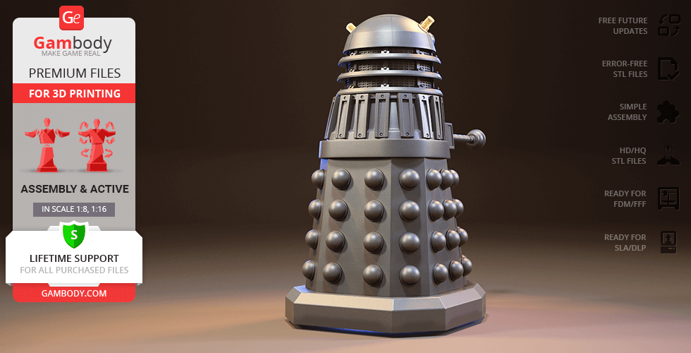
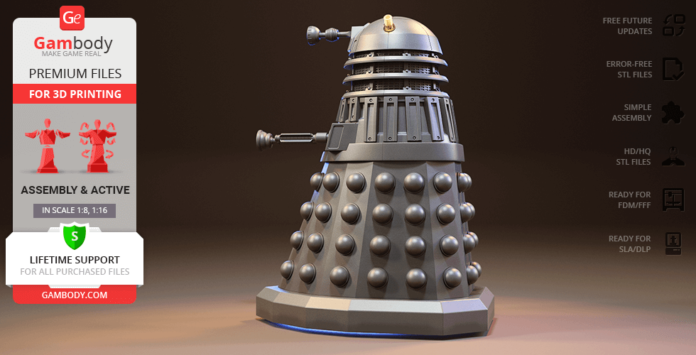
Daleks are ferocious representatives of the warrior race originating from planet Skaro and depicted in the British science fiction TV show Doctor Who. These seemingly robotic aliens are, in fact, cyborgs - highly intelligent genetically altered by the mad genius Davros mutants sealed within a nearly impregnable tank-like casing. Created to harbour no feelings except vehement hatred for all other living creatures and intent on purging all “inferior” beings, the Daleks provoke a state of terror across the universe. Inspired by the various Daleks’ designs throughout the years, our contributing 3D artist spent 148 hours on modelling the most recognizable villains in television history. Once you spot the model, the Dalek’s pepper pot resembling outer shell will instantly ring the bell. Just like its TV show counterpart, the Dalek 3D Printing model is divided into three major sections. The rotating dome-like head of the Dalek is equipped with a set of twin luminosity dischargers and a haunting periscope-like eyestalk. The grating section below connects the head with the weapons platform, where the Dalek’s threatening gunstick and manipulator arm are attached. Behind the secure metal plates of the weapon platform, a secret compartment designed to store the body of the mutant is located. The skirt-shaped bottom section of the cyborg serves as its main mean of mobility. The outer shell of it is fitted with partially embedded spherical protrusions that act as part of the Dalek’s sensory array. Such a sturdy base ensures the smooth gliding motion of the savage warrior and will help uphold the model on the shelf of your collection. Don’t miss your chance to 3D print Dalek and create a bizarre installation of space and time travel!
ADAPTATION FOR 3D PRINTING
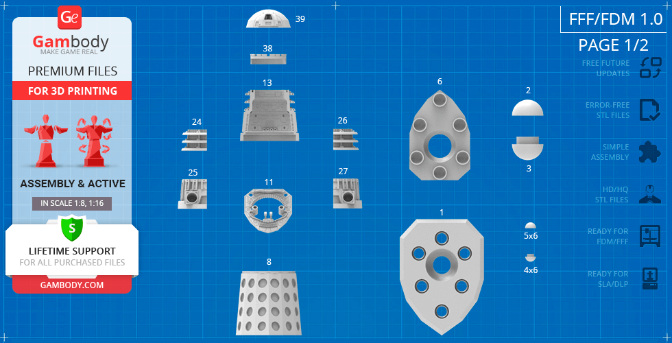
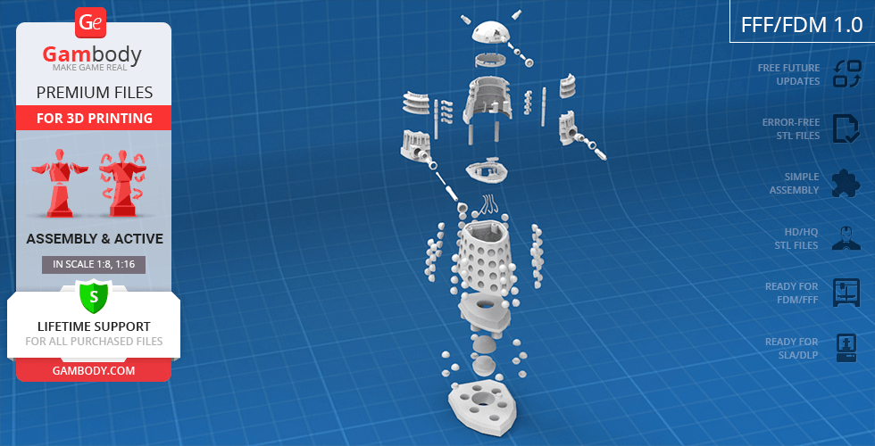
Dalek model for 3D printing is a highly articulated action assembly model and its moderation and adaptation for different types of 3D printers took Gambody team 50 hours in total. For you to receive the cleanest 3D printing result possible and to minimize the amount of filament needed for generated support the fictional cyborg model was divided into many assembly parts, e.g. its Blast Gun, telescopic Control Arm, “sense globes”, “light bulbs” etc. are provided as separate STL files. Various special mechanisms were introduced to ensure that the model has fully articulated elements in it (please, see “Versions’ Specifications”). All assembly parts are provided in STL files in recommended positions that were worked out in order to ensure the smoothness of the details’ surfaces after printing and that the 3D printing beginners won't face difficulties when placing the parts on a build plate. When downloading any model's file you will also receive "Assembly Manual" for FFF/FDM 1.0 and DLP/SLA/SLS 1.0 versions in PDF format. We highly recommend that you get acquainted with the “Assembly video” and "Assembly Manual" before getting down to the Dalek model.
The model is saved in STL files, a format supported by most 3D printers. All STL files for 3D printing have been checked in Netfabb and no errors were shown.
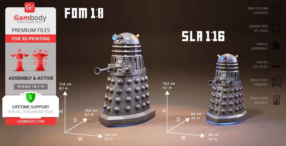
The model's scale was calculated from the actual height of Dalek that is 1020 mm. The 3D printing model's chosen scale is 1/8 for FFF/FDM version and 1/16 for DLP/SLA/SLS version.
VERSIONS' SPECIFICATIONS
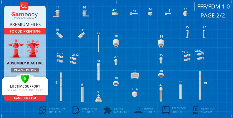
FFF/FDM 1.0 version features:
- Contains 46 parts;
- A printed robot is 210 mm tall, 120 mm wide, 169 mm deep;
- Dalek’s main motor globe, as well as smaller stabilizer globes fully rotate to propel the Dalek in any direction (similar to a computer mouse ball);
- Dalek's dome (head) revolves on its axis;
- The Eyestick moves vertically via a ratchet mechanism;
- Each of Dalek’s four doors opens independently with the help of a set of hinges; bottom doors can also be slightly lowered;
- The Blast Gun and Control Arm are assembled with an adjustable grip connector that can fully rotate;
- The Control Arm is telescopic;
- The “light bulbs” (the Luminosity Dischargers) on the cyborg's dome are provided separately and can be printed with the transparent filament;
- Decorative wires inside Dalek's dome do not come in STL files but can be made out of short pieces of regular 1.75 PLA;
- Tunnels throughout the robot’s hollow body are provided for LED wiring to light up the highly-detailed interior, as well as the “light bulbs”;
- It is highly recommended that you watch "Assembly video" in the photo preview section before assembling Dalek;
- All parts are divided in such a way that you will print them with the smallest number of support structures.
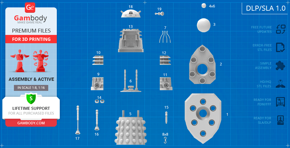
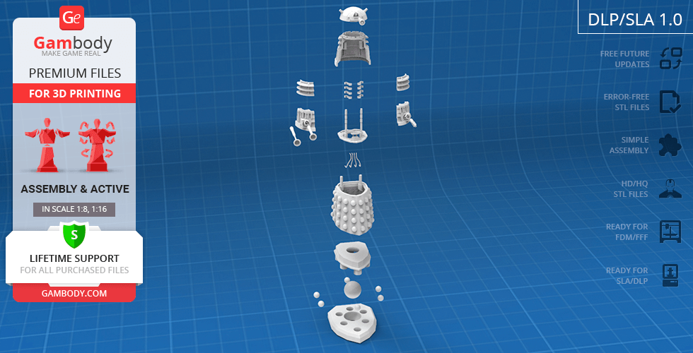
DLP/SLA/SLS 1.0 version features:
- Contains 19 parts;
- A printed model is 105 mm tall, 60 mm wide, 85 mm deep;
- Dalek’s main motor globe, as well as smaller stabilizer globes fully rotate to propel the Dalek in any direction (similar to a computer mouse ball);
- Dalek's dome (head) revolves on its axis, while the Eyestick moves vertically;
- Each of Dalek’s four doors opens independently with the help of a set of hinges; bottom doors can also be slightly lowered;
- The Blast Gun and Control Arm can fully rotate;
- Tunnels throughout the robot’s hollow body are provided for LED wiring to light up the highly-detailed interior, as well as the “light bulbs”;
- It is highly recommended that you watch "Assembly video" in the photo preview section before assembling Dalek;
- All parts are divided in such a way to fit the build plates and to ensure that support structures are generated where needed.
WHAT WILL YOU GET AFTER PURCHASE?
- STL files of Dalek Model for 3D printing which consist of 65 parts;
- 2 versions of files for this model for FFF/FDM and DLP/SLA/SLS printers;
- High-poly detailed model of Dalek;
- Assembly Manual for FFF/FDM 1.0 and DLP/SLA 1.0 versions in PDF format;
- Detailed settings that we provide as a recommendation for Cura , Simplify3D and Slic3r for the best print;
- Full technical support from the Gambody Support Team.
You can get the model of Dalek for 3D Printing immediately after the purchase! Just click the green Buy button in the top-right corner of the model’s page. You can pay with PayPal or your credit card.
Watch the tutorial on how to assemble Dalek 3D Printing Model at Gambody YouTube channel.
Also, you may like other Villain 3D Printing Figurines, as well as other Robot 3D Printing Models.
_______
FAQ:
Where can I print a model if I have no printer?
How to get started with 3D printing?
How to set up my 3D printer?
How to choose right 3D model print bed positioning?
How to paint printed figurine?
Average customer rating (9 reviews)
4.9
Ratings breakdown
Click a star rating to filter reviews
Overall experience
Level of detail in the model
4.9
Model cut quality and assembly guide
5
Clarity and accuracy of the model page
4.9
Level of detail in the model
3.9
Model cut quality and assembly guide
4.6
Clarity and accuracy of the model page
4
We've noted all of your suggestions regarding the gun design, separate shoulder slats, and the inclusion of the Dalek Mutant STL file, and have forwarded them to the model's author, Ethan Jones, as well as our Moderation Team for consideration. There's a good chance these ideas will be taken into account in one of the future updates.
By the way, we'd love to see how your Dalek turned out! You're welcome to share a few photos here in the Feedback section or in our Gambody 3D Printing Community – we're sure fellow Doctor Who fans would love to see it too!
https://www.facebook.com/groups/183216945475583
We hope you enjoyed working on this project! Thank you again for helping us improve the model!
Level of detail in the model
5
Model cut quality and assembly guide
5
Clarity and accuracy of the model page
5
Level of detail in the model
5
Model cut quality and assembly guide
5
Clarity and accuracy of the model page
5
Level of detail in the model
5
Model cut quality and assembly guide
5
Clarity and accuracy of the model page
5
Level of detail in the model
5
Model cut quality and assembly guide
5
Clarity and accuracy of the model page
5
Level of detail in the model
5
Model cut quality and assembly guide
5
Clarity and accuracy of the model page
5
Level of detail in the model
5
Model cut quality and assembly guide
5
Clarity and accuracy of the model page
5
Level of detail in the model
5
Model cut quality and assembly guide
5
Clarity and accuracy of the model page
5
Level of detail in the model
5
Model cut quality and assembly guide
5
Clarity and accuracy of the model page
5
Below you'll find detailed slicing settings for Bambu Studio 2.0+, Orca Slicer 2.0+, UltiMaker Cura 5.0+, PrusaSlicer 2.0+, Slic3r 1.3+, Simplify3D 5.0+ to help you get the best results when printing this model. These settings are optimized specifically for this 3D model, but please note they may need slight adjustments depending on your printer or filament. When in doubt, refer to your printer's user manual.
To avoid printing issues and achieve the best quality, we highly recommend applying the following settings:
For better quality use 0.12 mm layer height, for fast printing use 0.2 mm layer height. For pins and the Ge connectors, use 0.2 layer height.
120-150% of your Layer Height
But you can paint the seam if you want.
You have to calibrate this parameter
You have to calibrate this parameter
You have to calibrate this parameter
For pins and power elements of the structure, such as the vehicle frame, use 3 loop
Disabled for vehicles and enabled for characters
For 0,2 Layer Height
The parameters in this tab vary greatly, it all depends on the quality of your printer. For example, if you have a classic Ender3, stick to the minimum parameters, but if you have a newer printer, for example Anycubic cobra 3 v2, you can select the maximum recommended values
Settings for advanced users, change these parameters only if you have sufficient 3D printing expertise
Enable this parameter if your model requires supports
We also recommend placing and removing supports manually in some places using special button
1-2 loops for more thick support
Top Z distance = 1-1.3 layer Height. If the supports are hard to remove, try increasing this setting by 0.1-0,4 mm
Bottom Z distance = 1-1.3 layer Height. If the supports are hard to remove, try increasing this setting by 0.1-0,4 mm
You have to calibrate this parameter which one is better for your filament
Increase this parameter if the supports are hard to remove from walls
For PLA and PETG filament types
5-8 mm is optional for small prints that have bad adhesion to the build plate
You have to calibrate this parameter
Read the description on your filament roll
Read the description on your filament roll and increase this parameter for fast printers
Read the description on your filament roll and increase this parameter for fast printers
For better quality use 0.12 mm layer height, for fast printing use 0.2 mm layer height. For pins and the Ge connectors, use 0.2 layer height.
120-150% of your Layer Height
But you can paint the seam if you want.
0.01-0.05 You have to calibrate this parameter
0.01-0.05 You have to calibrate this parameter
0.1-0.2 You have to calibrate this parameter
For pins and power elements of the structure, such as the vehicle frame, use 3 loop
Disabled for vehicles and ships, enabled for characters
For 0,2 Layer Height
For 0,2 Layer Height
The parameters in this tab vary greatly, it all depends on the quality of your printer. For example, if you have a classic Ender3, stick to the minimum parameters, but if you have a newer printer, for example, Anycubic Kobra 3 Or Bambulab A1, you can select the maximum recommended values.
Settings for advanced users, change these parameters only if you have sufficient 3D printing expertise
Enable this parameter if your model requires supports
We also recommend placing and removing supports manually in some places using special button
Top Z distance = 1-1.3 layer Height. If the supports are hard to remove, try increasing this setting by 0.1-0,4 mm
Bottom Z distance = 1-1.3 layer Height. If the supports are hard to remove, try increasing this setting by 0.1-0,4 mm
Increase this parameter if the supports are hard to remove from walls
For PLA and PETG filament types
5-8 mm is optional for small prints that have bad adhesion to the build plate
Read the description on your filament roll
Read the description on your filament roll and increase this parameter for fast printers
You have to calibrate this parameter
Read the description on your filament roll and increase this parameter for fast printers
Read the description on your filament roll
This field is filled in according to your printer specifications when you add it to the slicer.
You can add custom G-code here for the start and end of the print. However, be careful - this is for advanced users only!
You have to calibrate your printer using Ge retraction test models
Retraction Length: For direct-drive setups use 0.5 mm to 2.5 mm; for Bowden extruders use 5 to 7 mm
This is how fast the filament is pulled back—40-60 mm/s for direct drive and 30-50 mm/s for Bowden setups.
You have to calibrate this parameter: Reduce it until the printer starts to hit the parts with the nozzle during printing, then increase it by 0.2.
For better quality use 0.12 mm layer height, for fast printing use 0.2 mm layer height. For pins and the Ge connectors, use 0.2 layer height.
120-150% of your Layer Height
To increase the strength of the print parts, use wall line count: 3
For pins and connectors use 50% Infill
These parameters are for standard PLA plastic. If you are using a different type of plastic, check the printing temperature recommended by the manufacturer. Also, read the description on your filament spool. For fast printers, add +30 °C to the current parameters.
The parameters in this tab vary greatly, it all depends on the quality of your printer. For example, if you have a classic Ender3, stick to the minimum parameters, but if you have a newer printer, for example Anycubic cobra 3 v3, you can select the maximum recommended values
Settings for advanced users, change these parameters only if you have sufficient 3D printing expertise.
You need to calibrate this parameter using Gambody test models. These values are average values for a Direct Drive extruder; for a Bowden extruder, the values should be increased.
You need to calibrate this parameter using Gambody test models. These values are average values for a Direct Drive extruder; for a Bowden extruder, the values should be increased.
Use this value other than 0 if your nozzle catches on the internal infill during travel moves. Try to keep this value as low as possible in height.
Use normal supports to support large, straight surfaces (most mechanical or technical parts).
You have to calibrate this parameter according to the capabilities of your printer and your filament, using a Gambody test models.
Use 1 instead of 0 if your supports are thin and tall. They will be harder to remove, but much stronger.
Top Z distance = 1-1.3 layer Height. If the supports are hard to remove, try increasing this setting by 0.1-0,4 mm
Increase this parameter if the supports are hard to remove from walls
Use tree supports to support complex objects, such as characters.
You have to calibrate this parameter according to the capabilities of your printer and your filament, using a Gambody test models.
Top Z distance = 1-1.3 layer Height. If the supports are hard to remove, try increasing this setting by 0.1-0,4 mm
Increase this parameter if the supports are hard to remove from walls
Use a skirt for all parts when printing on outdated printers.
Use a brim when printing thin but tall parts, as well as parts with a small bed adhesion area.
For better quality use 0.12 mm layer height, for fast printing use 0.2 mm layer height. For pins and the Ge connectors, use 0.2 layer height.
120-150% of your Layer Height
for 0.2 Layer Height
But you can paint the seam if you want.
(for PLA and PETG)
(5-8 mm is optional for small prints that have bad adhesion to the build plate)
Enable this parameter if your model requires supports
(45-50 degree)You have to calibrate this parameter according to the capabilities of your printer
and your filament, using a Gambody test models.
Top contact Z distance = 1-1.3 layer Height. If the supports are hard to remove, try
increasing this setting by 0.1-0,4 mm
Top contact Z distance = 1-1.3 layer Height. If the supports are hard to remove, try
increasing this setting by 0.1-0,4 mm
Increase this parameter if the supports are hard to remove from walls
The parameters in this tab vary greatly, it all depends on the quality of your printer. For example, if you have a classic Ender3, stick to the minimum parameters, but if you have a newer printer, for example Anycubic cobra 3 v3, you can select the maximum recommended values
Settings for advanced users, change these parameters only if you have sufficient 3D printing expertise. Use the minimum value for outdated printers without acceleration calibration, and the maximum value for modern printers if you need it.
These settings only work for 3D printers with multiple extruders
You can try setting all parameters in this section, except the First layer, to values between 0.75% of your nozzle diameter and 1.25% of your nozzle diameter. Adjusting them will help you work out the optimal parameters for the best quality for your print. As for the First layer, you can set it to 150% of the diameter of your nozzle for better adhesion to the build plate (for a nozzle with a diameter of 0.4 mm, the First layer extrusion width can be from 0.3 mm to 0.5 mm)
For better printing quality you have to calibrate this parameter using Gambody test model.
Check your filament manufacturer's temperature recommendations on the spool.
Cooling parameters depends on the material you use for printing.
*for PLA
For better quality use 0.12 mm layer height, for fast printing use 0.2 mm layer height. For pins and the Ge connectors, use 0.2 layer height.
120-150% of your Layer Height
For 0.12 Layer Height
For 0.12 Layer Height
For pins and connectors use 50% Infill
Use skirt for outdated 3d printers
(5-8 mm is optional for small prints that have bad adhesion to the build plate)
Enable this parameter if your model requires supports
(45-60 degree)You have to calibrate this parameter according to the capabilities of your printer and your filament, using a Gambody test models
Contact Z distance = 1-1.3 layer Height. If the supports are hard to remove, try increasing this setting by 0.1-0,4 mm
The parameters in this tab vary greatly, it all depends on the quality of your printer. For example, if you have a classic Ender3, stick to the minimum parameters, but if you have a newer printer, for example Anycubic cobra 3 v3, you can select the maximum recommended values
Settings for advanced users, change these parameters only if you have sufficient 3D printing expertise. Use the minimum value for outdated printers without acceleration calibration, and the maximum value for modern printers if you need it.
You have to calibrate this parameter from 0.9 to 1.1 according to the capabilities of your printer and your filament, using a Gambody test models.
Check your filament manufacturer's temperature recommendations on the spool.
Cooling parameters depends on the material you use for printing.
Calibrate this value if you need to reduce or improve the adhesion between the plastic and the heat bed
Your current nozzle diameter
You need to calibrate this parameter using Gambody test models. These values are average values for a Direct Drive extruder; for a Bowden extruder, the values should be increased.
Your current nozzle diameter
You have to calibrate this parameter using Gambody test models.
You need to calibrate this parameter using Gambody test models. These values are average values for a Direct Drive extruder; for a Bowden extruder, the values should be increased.
For better quality use 0.12 mm layer height, for fast printing use 0.2 mm layer height. For pins and the Ge connectors, use 0.2 layer height.
For 0,2 Layer Height
For 0,2 Layer Height
To increase the strength of the print parts, use Outline Perimeters: 3
You can enable this parameter to print rounded or spherical models, as well as character models.
Use this option only if your parts are too tight. but better calibrate your printer extrusion
Use this option only if your parts are too tight. but better calibrate your printer extrusion
Use 2 and more if you want to create skirt instead brim
1-2 for skirt and 10-20 for brim
Use for wipe nozzle if you need
Use For ABS filament
For pins and connectors use 50% Infill
Top Z distance = 1-1.3 layer Height. If the supports are hard to remove, try increasing this setting by 0.1-0,4 mm
Calibrate your filament and detect optimal temperature for it
Average temperature for PLA filament
The parameters in this tab vary greatly, it all depends on the quality of your printer. For example, if you have a classic Ender3, stick to the minimum parameters, but if you have a newer printer, for example Anycubic cobra 3 v3, you can select the maximum recommended values
Settings for advanced users, change these parameters only if you have sufficient 3D printing expertise.
DLP/SLA
- Dalek’s main motor globe, as well as smaller stabilizer globes fully rotate to propel the Dalek in any direction (similar to a computer mouse ball);
- Dalek's dome (head) revolves on its axis, while the Eyestick moves vertically;
- Each of Dalek’s four doors opens independently with the help of a set of hinges; bottom doors can also be slightly lowered;
- The Blast Gun and Control Arm can fully rotate;
- Tunnels throughout the robot’s hollow body are provided for LED wiring to light up the highly-detailed interior, as well as the “light bulbs”
FFF/FDM
- Dalek’s main motor globe, as well as smaller stabilizer globes fully rotate to propel the Dalek in any direction (similar to a computer mouse ball);
- Dalek's dome (head) revolves on its axis;
- The Eyestick moves vertically via a ratchet mechanism;
- Each of Dalek’s four doors opens independently with the help of a set of hinges; bottom doors can also be slightly lowered;
- The Blast Gun and Control Arm are assembled with an adjustable grip connector that can fully rotate;
- The Control Arm is telescopic;
- The “light bulbs” (the Luminosity Dischargers) on the cyborg's dome are provided separately and can be printed with the transparent filament;
- Decorative wires inside Dalek's dome do not come in STL files but can be made out of short pieces of regular 1.75 PLA;
- Tunnels throughout the robot’s hollow body are provided for LED wiring to light up the highly-detailed interior, as well as the “light bulbs”;