

Files
3D model format
Stereolithography (.stl)
Total files
Slicer settings
Mesh error check
Netfabb
Support
Lifetime support from Gambody team
Update requests
Available to verified buyers
Model complexity
Expert: demanding print setup with intricate parts. Requires post-processing skills, attention to detail, and patience.
Model versions
FFF/FDM
Assembly method
not specified
Features
FFF/FDM
Assembly method
not specified
Features
FFF/FDM
Assembly method
not specified
Features
FFF/FDM
Assembly method
not specified
Features
Additional details
Part of diorama
Yes
Other model in diorama
Special pack included
No
You will get instant access to the STL files of War Rig Truck 3D Printing Model | Assembly + Action after completing your purchase. Simply add the model to your cart and check out using PayPal, credit or debit card, Apple Pay, Google Pay, Alipay, or other available payment methods.
Watch the assembly video for War Rig Truck 3D Printing Model | Assembly + Action, and explore more tutorials, behind-the-scenes content, 3D printing timelapses, and painting guides on the official Gambody YouTube channel.
This 3D Model consists of files in StereoLithography (.Stl) format that is optimized for 3D printing.
Before printing the files, we strongly recommend reading the PRINTING DETAILS section.
War Rig Truck 3D Printing Model comes in 2 versions for FFF/FDM 3D printers. STL files of each version are available for download after the purchase.
Detailed information about this 3D printing model is available in the DESCRIPTION section.
Before printing, take a look at Printing Details for recommended settings and tips to achieve better results.
ABOUT THIS 3D MODEL
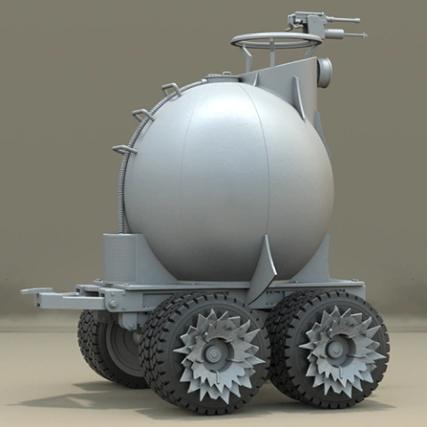
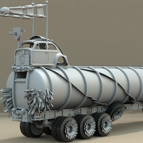
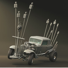
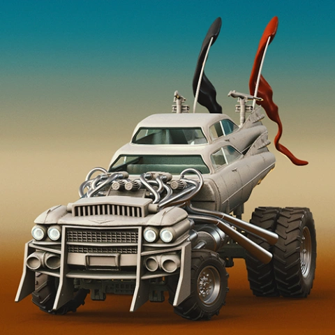
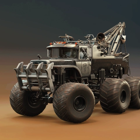
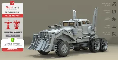
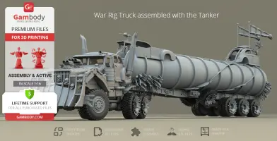
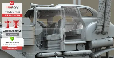
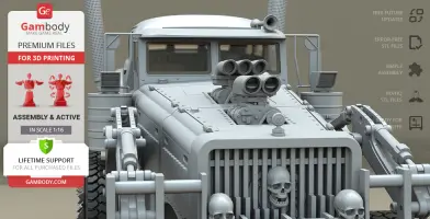
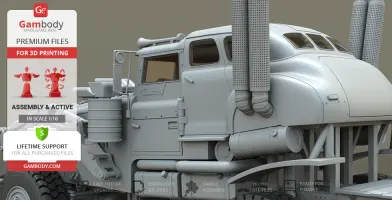
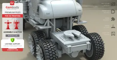
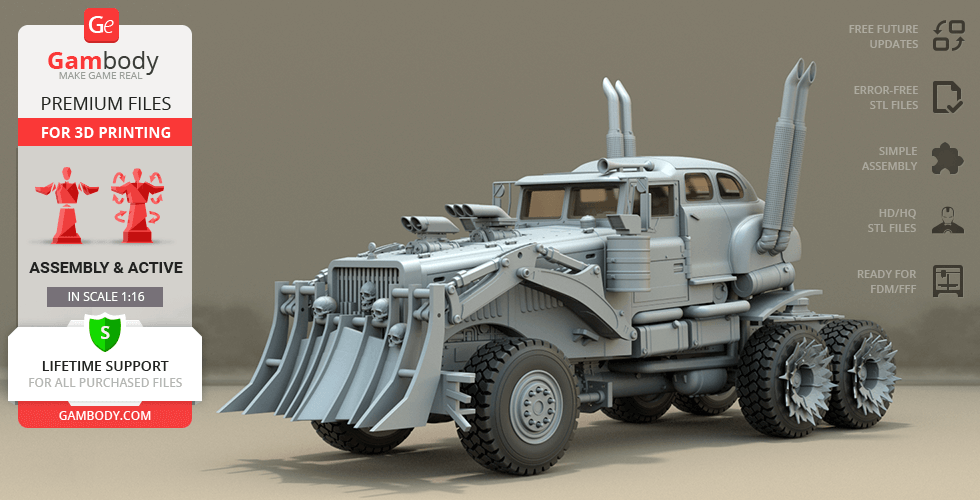
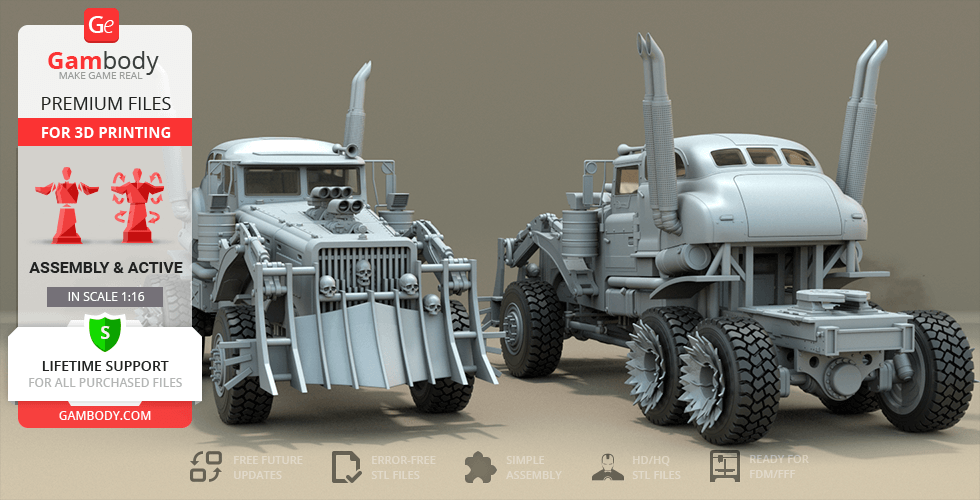
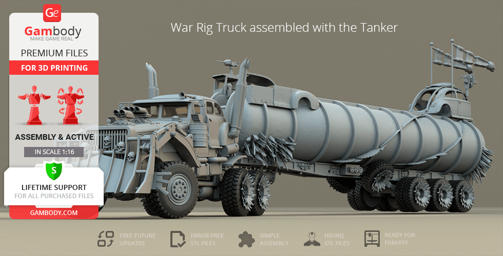
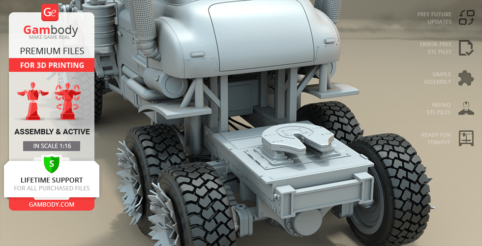
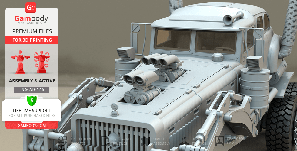
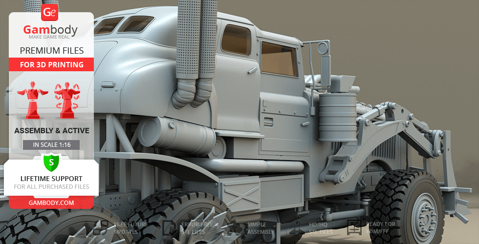
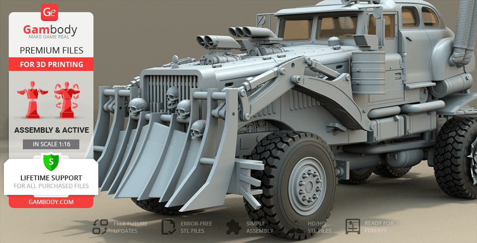
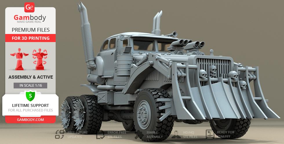
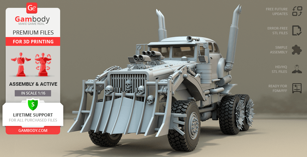
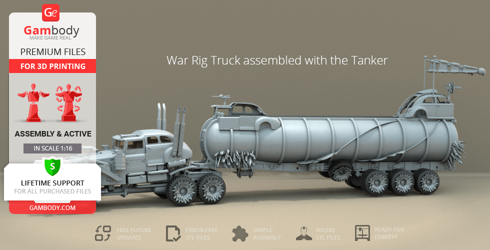
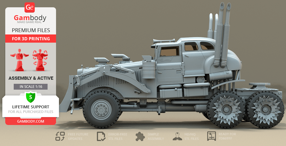
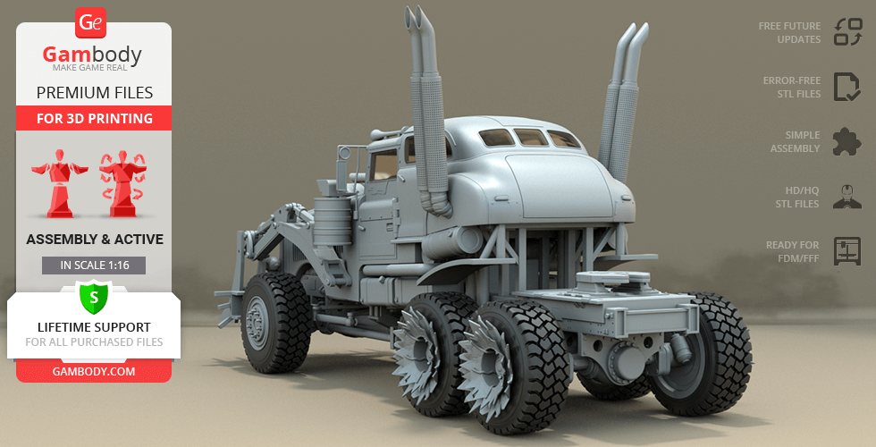
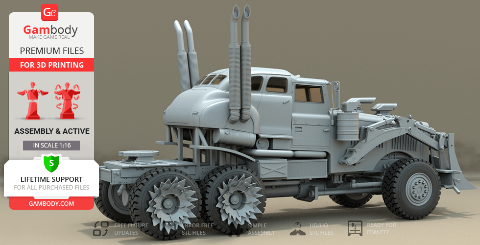
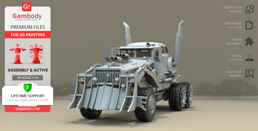
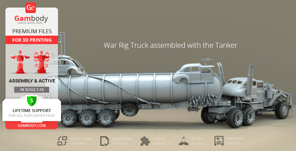
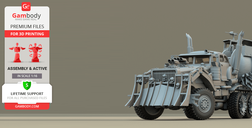
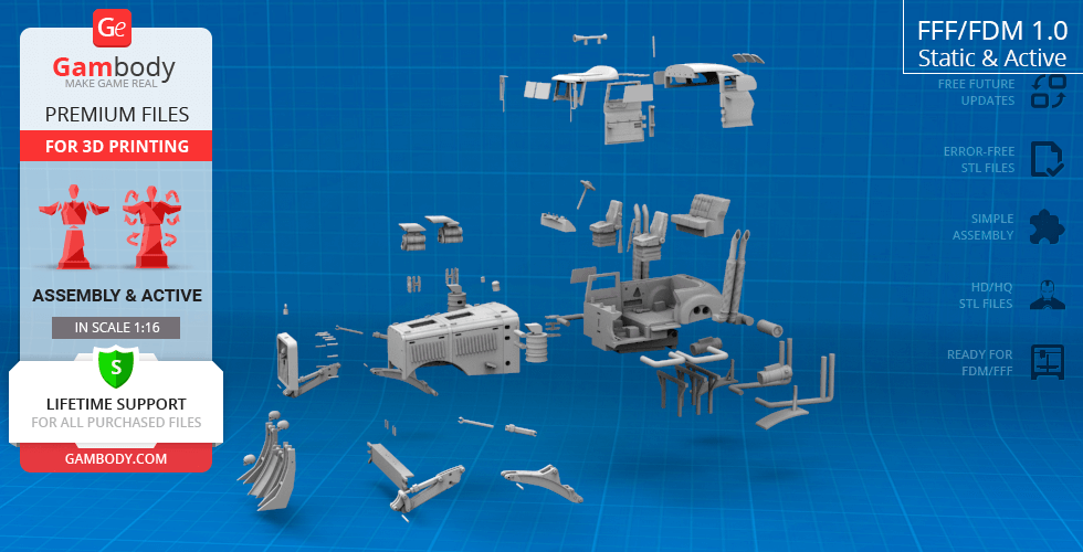
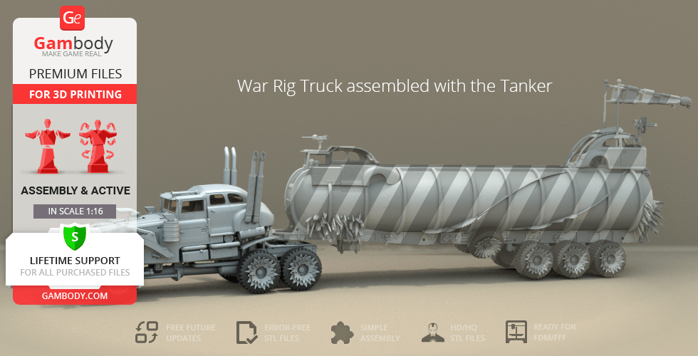
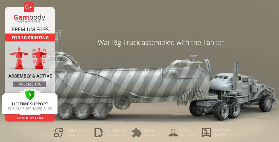
Mad Max: Fury Road is the fourth installment of the legendary Mad Max franchise that is recognized as one of the best action movies of the passing decade. The thrilling sequence of the action-packed road war and the outstanding visual aesthetics of the movie do not lose sight of the compelling story. The plot revolves around the extraordinary warrior Imperator Furiosa who grows close bonds with Immortan Joe’s Five Wives, helps the women flee his tyrannical grasp and fights off a swarm of War Boys not without the help of Max Rockatansky. In the classic spirit of Mad Max, the dangerous journey across the Wasteland takes place aboard a plethora of bizarre custom vehicles, one of them being the War Rig that Furiosa hijacks from Immortan Joe's vehicular fleet. This impressive all-wheel-drive Truck was based on the Tatra T815 and modified with a custom front built from 1947-48 Chevrolet Fleetmaster Sedan. Inspired by such a monstrous vehicle, our contributing 3D artist decided to recreate the War Rig in the form of a 3D model and dedicated over 120 hours working on the project. The front of the truck is equipped with a massive cowcatcher mounted onto tractor digger arms, two Holley superchargers are placed on top of the hood. The grille of War Rig is decorated with human skulls that are Immortan Joe’s distinctive attributes. Both sides are furnished with a pair of tall exhaust stacks. Just like in its original design, the tractor features two pairs of suicide rear-hinged doors that display the interior design when opened. The hubcaps of the truck are armored with sharpened metal to protect the wheels from attackers and deal damage to the enemy’s vehicles. Such an incredible modified Truck has long become one of the icons of the Mad Max franchise, and with the help of Gambody model for 3D printing, it will be the brightest star of your personal collection! Especially, when there are a fantastic War Rig Tanker and a Fuel Pod to complement this epic Furiosa’s Truck!
ADAPTATION FOR 3D PRINTING
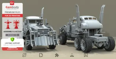
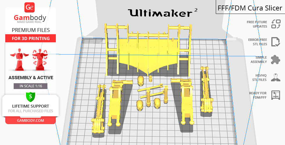
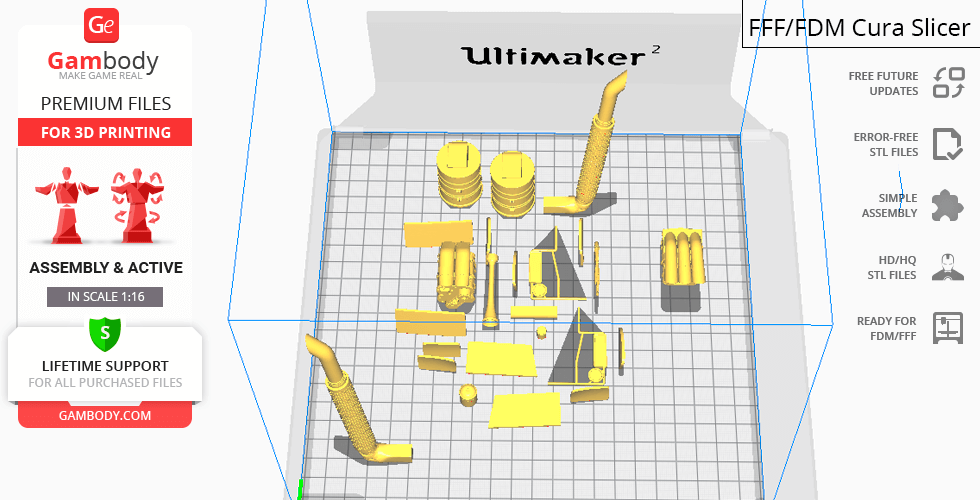
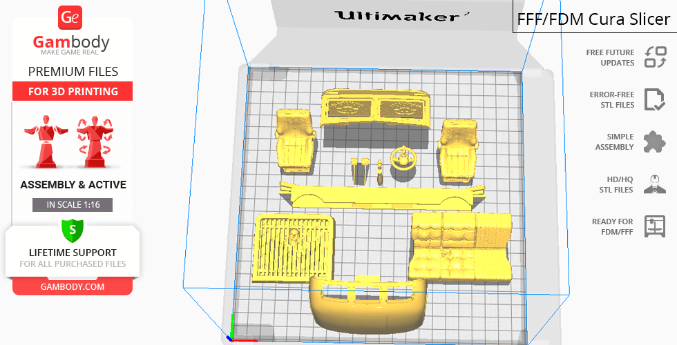
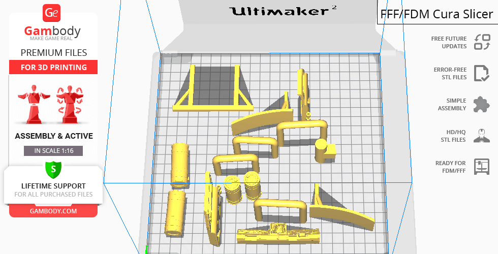
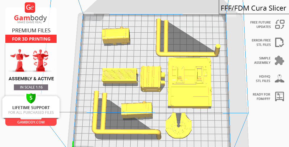
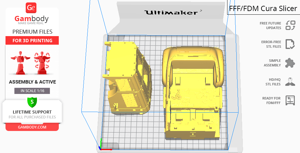
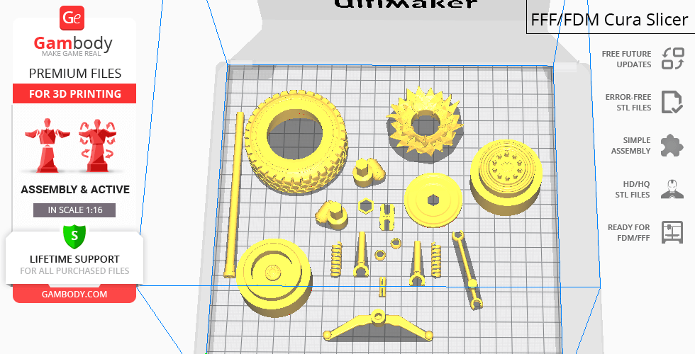
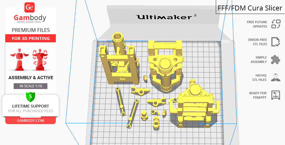
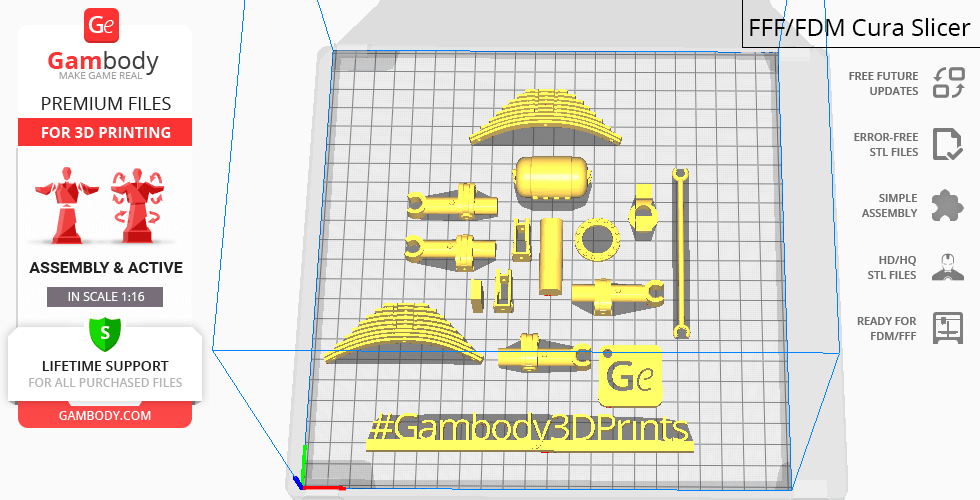
War Rig Truck 3D printing model is a highly-detailed assembly model and its moderation and adaptation for different types of 3D printers took Gambody team 144 hours in total. In order to preserve the accurate likeness of the original Tatra T815, as well as the modified movie War Rig Truck, the model was divided into many parts that are to be assembled as if a real vehicle. Taking into account the willingness of our customers to make their 3D printing projects as true to life as possible, the Gambody team prepared two separate versions of the Truck that differ in the type of the suspension assembly (active or static). Thus, various special mechanisms were introduced into the model to make sure that the parts comprising both suspensions, as well as the details of the frame and the floor pan, are both authentic and highly functional (please, see "Versions' specifications", "Assembly video" and photo preview slider). Moreover, in order to stay true to the Furiosa vehicle's massive size, the model was divided into as many assembly parts as needed to ensure that it will fit any 3D printer's build plate. The cutting of the model was chosen to ensure the cleanest 3D printing result possible and to minimize the amount of material needed to print the generated support, e.g. Truck’s grille, decorative skulls, air horn, seats, fifth wheel, fuel tanks, opening doors, exhaust pipes, stick shift, steering wheel, dashboard, cowcatcher, and many many more parts come as separate STL files. All assembly parts are provided in STL files in recommended positions that were worked out in order to ensure the smoothness of the details’ surfaces after printing and so that the 3D printing beginners won't face difficulties when placing the parts on a build plate. The model's assembly requires additional "pins" to secure the parts of the 3D printed Truck. These pins do not come in STL files but can be made out of short pieces of regular 1.75 PLA. We highly recommend that you watch "Assembly video" in the photo preview section before assembling the War Rig Truck.
The model is saved in STL files, a format supported by most 3D printers. All STL files for 3D printing have been checked in Netfabb and no errors were shown.
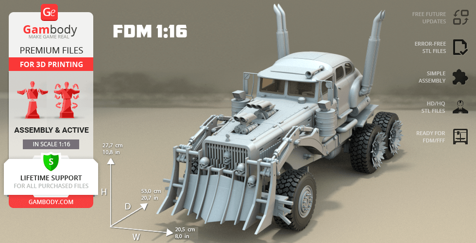
The model's scale was calculated from the actual length of the War Rig's truck that is 8520 mm. The 3D printing model's chosen scale is 1/16 for the FFF/FDM versions.
VERSIONS' SPECIFICATIONS
Files #1 - 85, as well as the following features, are identical in both FFF/FDM Static 1.0andFFF/FDM Active 1.0 versions:
- When printed the Truck model stands 277 mm tall, 205 mm wide, 530 mm deep;
- Minimal recommended 3D printer build volume is 220 x 220 x 250 mm;
- Assembly kit includes lock 77_Ge_lock_10H_x15 to attach the model's parts securely without glue that needs to be printed 15 times;
- There are some assembly parts that need to be printed multiple times - the number of required copies (x2, x4 etc.) is indicated in the title of the file in "Source files", e.g. file "18_filter_connector_x4" needs to be printed 4 times;
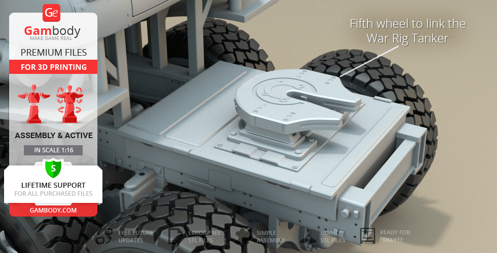
- The fifth wheel to link the War Rig Tanker that comes as a separate item;
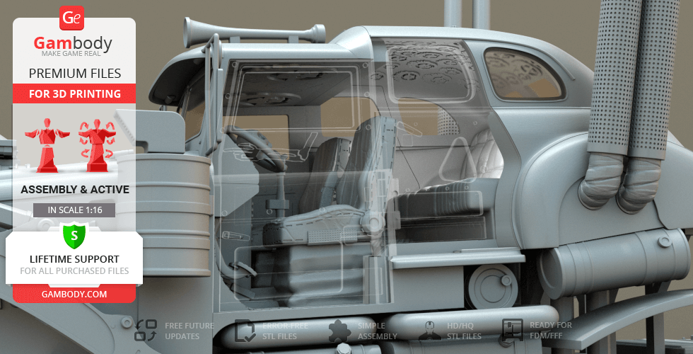
- Windscreens of the Rig, as well as all door glasses and quarters, are provided separately to be printed with the transparent filament;
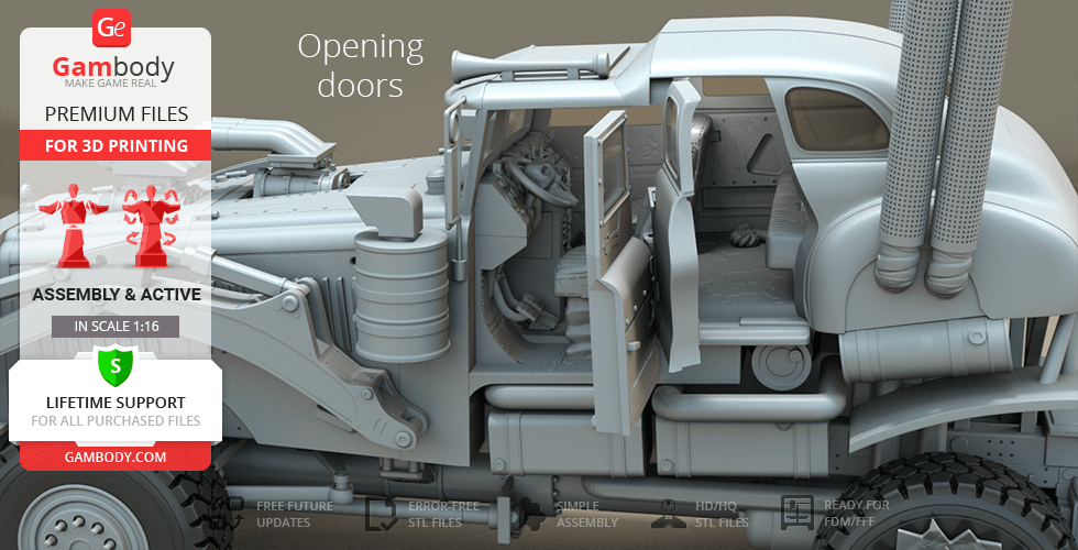
- Driver's suicide door and the door behind it can be opened;
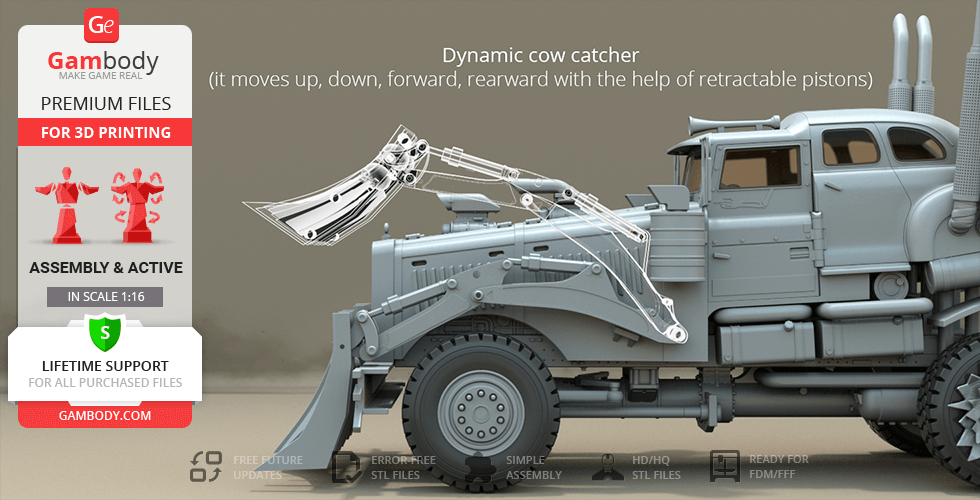
- Articulated cowcatcher can go up, down, forward, rearward with the help of retractable pistons;
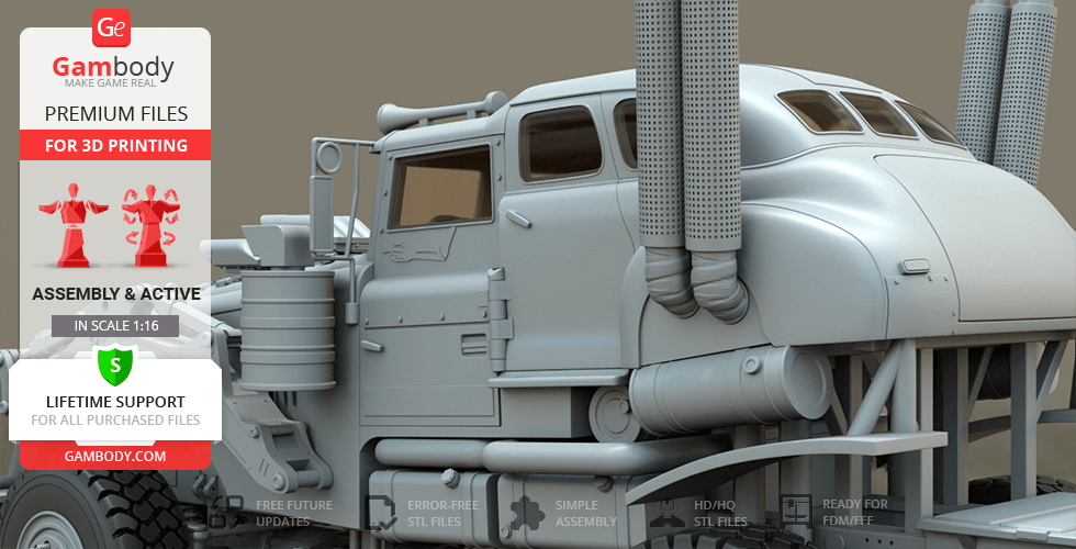
- Highly-detailed superchargers protruding through the bonnet;
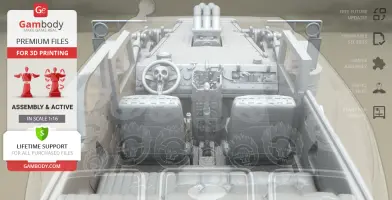
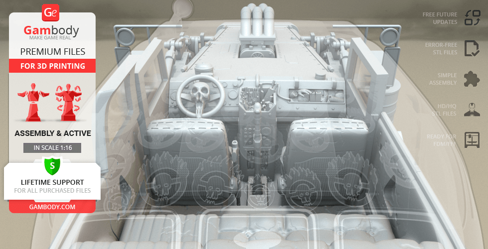
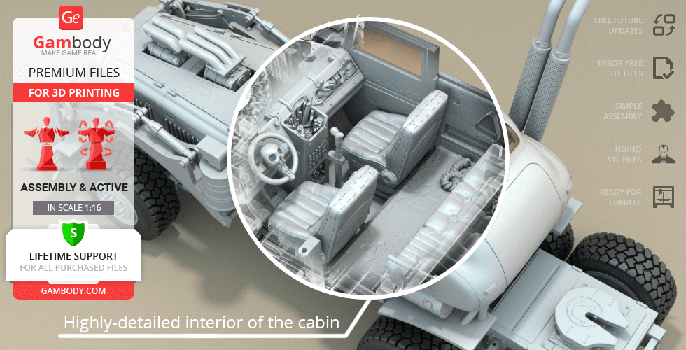
- The incredible detail of the cabin and its interior: a skeleton arm on the driver's door, Immortan's logo on the inside of the roof, stickshift, pedals, console full of switches, a toolbox, braided rugs, a shotgun, etc.;
- Rotating steering wheel with a skull;
- Fantastic attention to detail: air horn on the top of the cabin, massive exhaust pipes, fuel tanks, storage compartments, Motometer emblem on the bonnet, etc.;
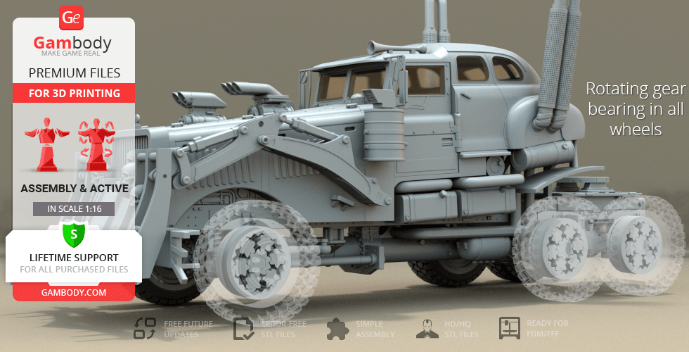
- Rotating gear bearings in all wheels;
- Two variants of wheel tyre to choose from: one is meant for plastic filament, the other is hollow for flexible material;
- We recommend that you watch the "Assembly video" before assembling the War Rig Truck;
- All parts are divided in such a way that you will print them with the smallest number of support structures.
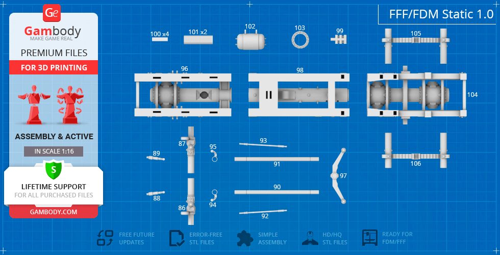
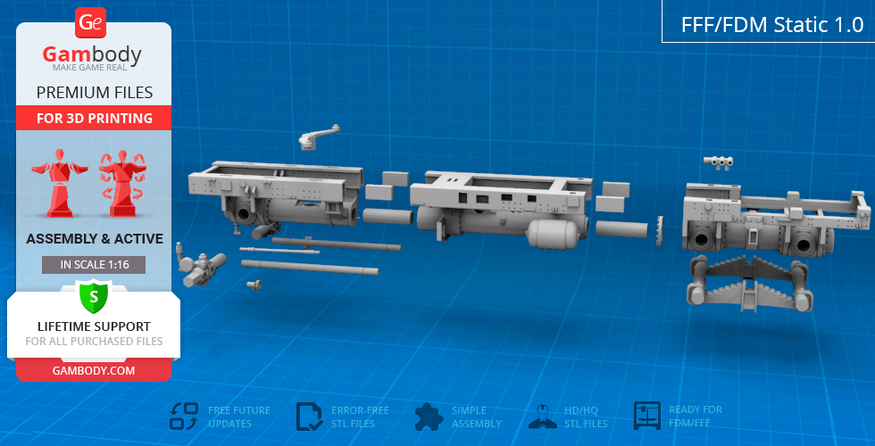
FFF/FDM Static 1.0 version features:
- Contains 106 parts;
- Frame with static suspension;
- A thorough study of the details of the frame and the floor pan assembly of the original Tatra T815;
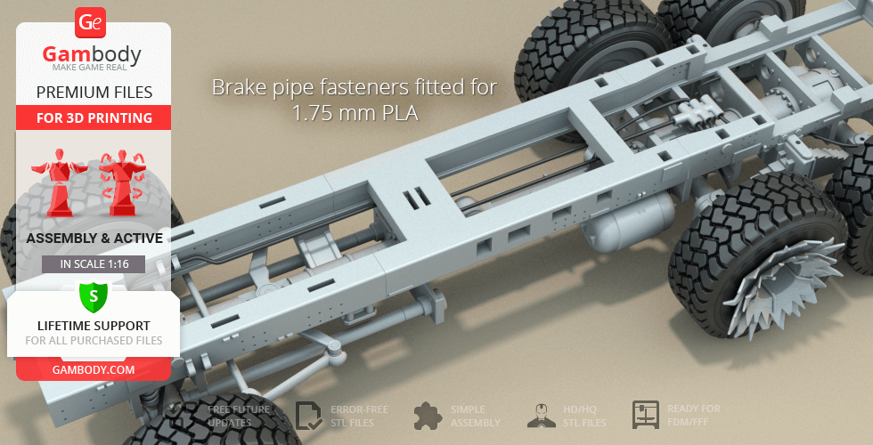
- Brake pipe fasteners fitted for 1.75mm PLA (the brake pipe does not come with STL files);
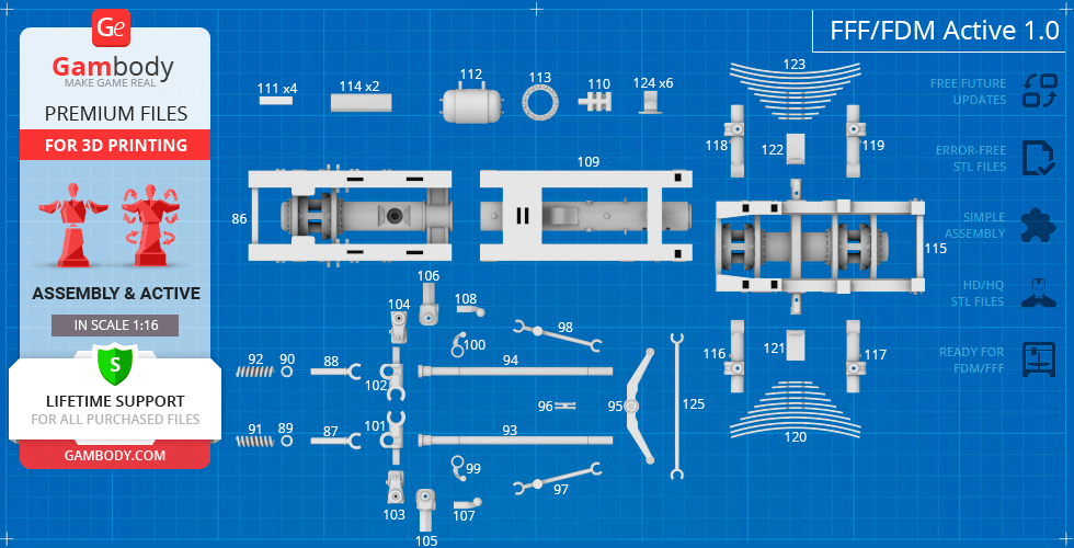
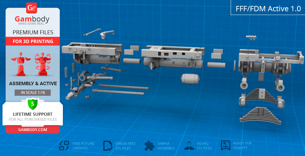
FFF/FDM Active 1.0 version features:
- Contains 125 parts;
- Frame with active suspension;
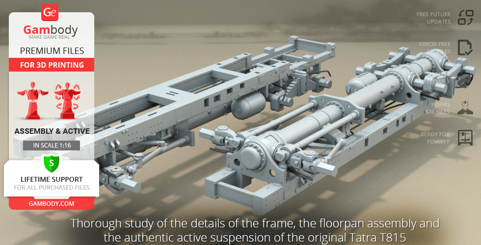
- A thorough study of the details of the frame, the floor pan assembly and the authentic active suspension of the original Tatra T815;
- Brake pipe fasteners fitted for 1.75mm PLA (the brake pipe does not come with STL files);
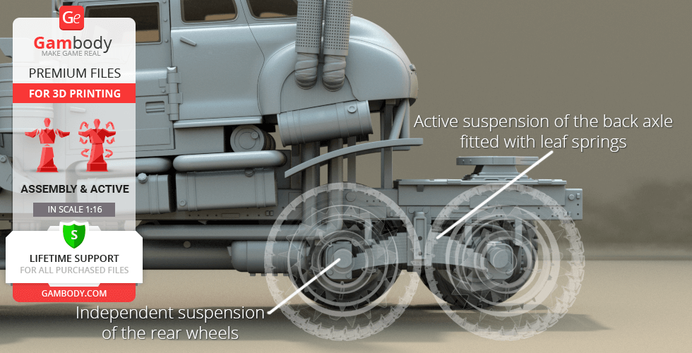
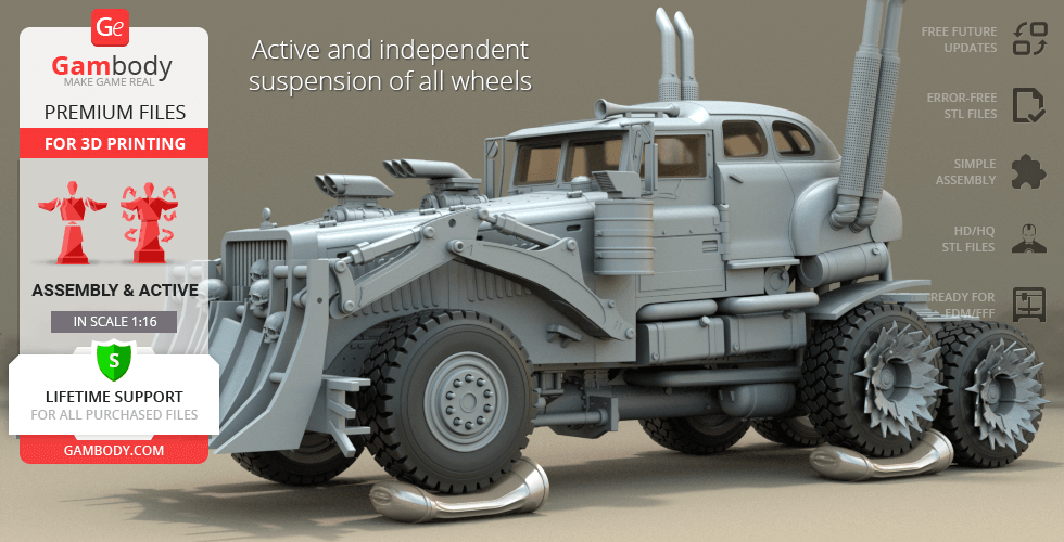
- Active suspension of the back axle fitted with leaf springs;
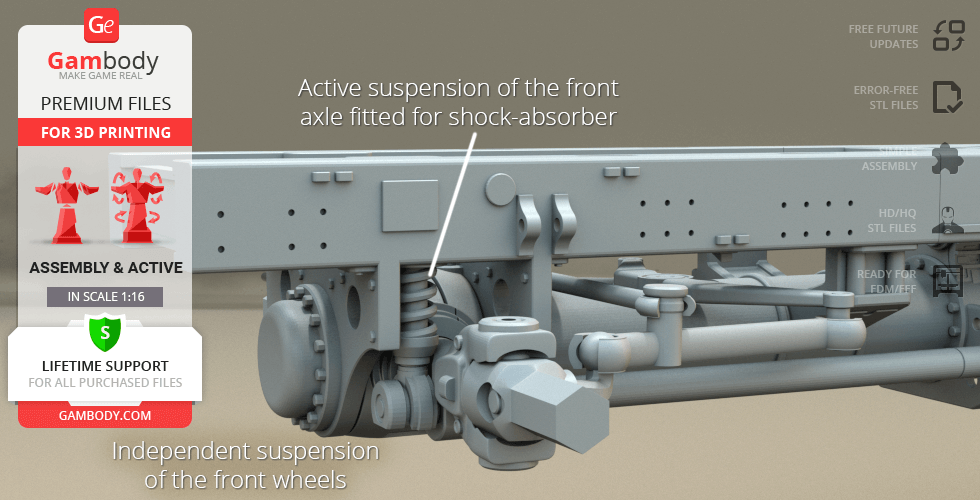
- Independent suspension of the rear and front wheels;
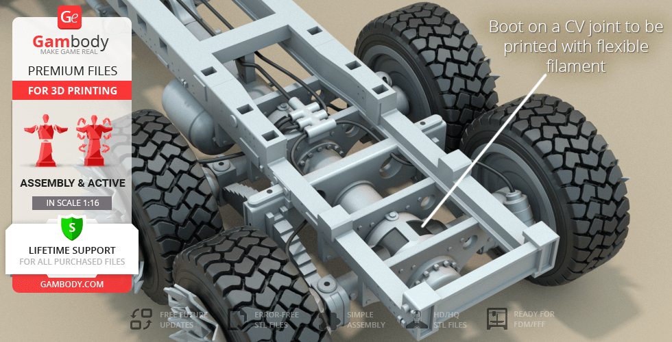
- Boot on a CV joint comes as a separate part to be printed with flexible filament;
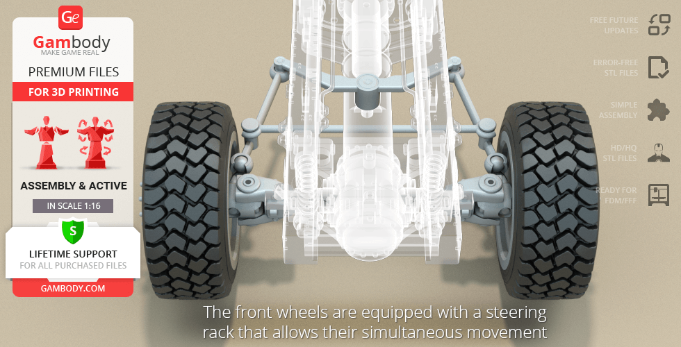
- The front wheels are equipped with a steering rack that allows their simultaneous movement;
- Active suspension of the front axle fitted for shock-absorber (you can also use any iron spring for better effect) and a torsion bar.
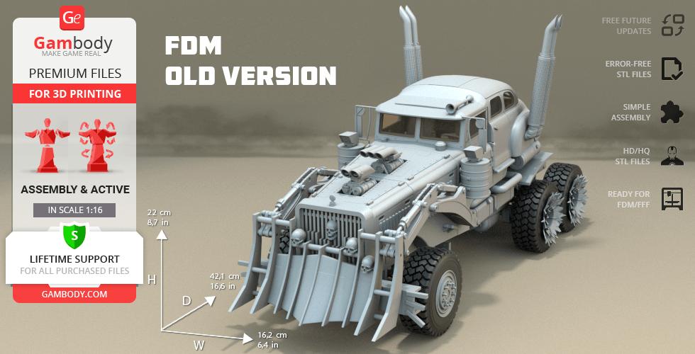
FFF/FDM Static (Old) & FFF/FDM Active (Old) versions features:
- Come in approximately 1:20 scale;
- Contain 106 and 125 parts respectively;
- When printed both versions stand 220 mm tall, 162 mm wide, 421 mm deep;
- The initial version of the War Rig model that was uploaded in an incorrect scale;
- These versions' features correspond with the ones of the FFF/FDM Static 1.0 and FFF/FDM Active 1.0 versions.
WHAT WILL YOU GET AFTER PURCHASE?
- STL files of War Rig Truck Model for 3D printing which consist of 231 parts;
- 2 versions of files for this model for FFF/FDM;
- High-poly detailed model of War Rig Truck;
- Detailed settings that we provide as a recommendation for Cura , Simplify3D and Slic3r for the best print;
- Full technical support from the Gambody Support Team.
You can get the model of War Rig Truck for 3D Printing immediately after the purchase! Just click the green Buy button in the top-right corner of the model’s page. You can pay with PayPal or your credit card.
Watch the tutorial on how to assemble War Rig Truck 3D Printing Model at Gambody YouTube channel.
Also, you may like the War Rig Tanker and War Rig Fuel Pod 3D Printing Models, as well as other Vehicle 3D Printing Models.
_______
FAQ:
Where can I print a model if I have no printer?
How to get started with 3D printing?
How to set up my 3D printer?
How to choose right 3D model print bed positioning?
How to paint printed figurine?
Average customer rating (26 reviews)
4.3
Ratings breakdown
Click a star rating to filter reviews
Overall experience
Level of detail in the model
4.3
Model cut quality and assembly guide
4.3
Clarity and accuracy of the model page
4.3
Level of detail in the model
4.5
Model cut quality and assembly guide
4.5
Clarity and accuracy of the model page
4.2
Level of detail in the model
5
Model cut quality and assembly guide
5
Clarity and accuracy of the model page
5
Level of detail in the model
5
Model cut quality and assembly guide
5
Clarity and accuracy of the model page
5
Level of detail in the model
5
Model cut quality and assembly guide
5
Clarity and accuracy of the model page
5
Level of detail in the model
5
Model cut quality and assembly guide
5
Clarity and accuracy of the model page
5
Level of detail in the model
5
Model cut quality and assembly guide
5
Clarity and accuracy of the model page
5
Level of detail in the model
5
Model cut quality and assembly guide
5
Clarity and accuracy of the model page
5
Level of detail in the model
2
Model cut quality and assembly guide
2
Clarity and accuracy of the model page
2
Level of detail in the model
4
Model cut quality and assembly guide
4
Clarity and accuracy of the model page
4
Level of detail in the model
4
Model cut quality and assembly guide
4
Clarity and accuracy of the model page
4
Level of detail in the model
5
Model cut quality and assembly guide
5
Clarity and accuracy of the model page
5
Level of detail in the model
2
Model cut quality and assembly guide
2
Clarity and accuracy of the model page
2
Level of detail in the model
5
Model cut quality and assembly guide
5
Clarity and accuracy of the model page
5
Level of detail in the model
5
Model cut quality and assembly guide
5
Clarity and accuracy of the model page
5
Level of detail in the model
2
Model cut quality and assembly guide
2
Clarity and accuracy of the model page
2
Level of detail in the model
2
Model cut quality and assembly guide
2
Clarity and accuracy of the model page
2
Level of detail in the model
3
Model cut quality and assembly guide
3
Clarity and accuracy of the model page
3
Level of detail in the model
5
Model cut quality and assembly guide
5
Clarity and accuracy of the model page
5
Level of detail in the model
4
Model cut quality and assembly guide
4
Clarity and accuracy of the model page
4
Level of detail in the model
5
Model cut quality and assembly guide
5
Clarity and accuracy of the model page
5
Below you'll find detailed slicing settings for Bambu Studio 2.0+, Orca Slicer 2.0+, UltiMaker Cura 5.0+, PrusaSlicer 2.0+, Slic3r 1.3+, Simplify3D 5.0+ to help you get the best results when printing this model. These settings are optimized specifically for this 3D model, but please note they may need slight adjustments depending on your printer or filament. When in doubt, refer to your printer's user manual.
To avoid printing issues and achieve the best quality, we highly recommend applying the following settings:
For better quality use 0.12 mm layer height, for fast printing use 0.2 mm layer height. For pins and the Ge connectors, use 0.2 layer height.
120-150% of your Layer Height
But you can paint the seam if you want.
You have to calibrate this parameter
You have to calibrate this parameter
You have to calibrate this parameter
For pins and power elements of the structure, such as the vehicle frame, use 3 loop
Disabled for vehicles and enabled for characters
For 0,2 Layer Height
The parameters in this tab vary greatly, it all depends on the quality of your printer. For example, if you have a classic Ender3, stick to the minimum parameters, but if you have a newer printer, for example Anycubic cobra 3 v2, you can select the maximum recommended values
Settings for advanced users, change these parameters only if you have sufficient 3D printing expertise
Enable this parameter if your model requires supports
We also recommend placing and removing supports manually in some places using special button
1-2 loops for more thick support
Top Z distance = 1-1.3 layer Height. If the supports are hard to remove, try increasing this setting by 0.1-0,4 mm
Bottom Z distance = 1-1.3 layer Height. If the supports are hard to remove, try increasing this setting by 0.1-0,4 mm
You have to calibrate this parameter which one is better for your filament
Increase this parameter if the supports are hard to remove from walls
For PLA and PETG filament types
5-8 mm is optional for small prints that have bad adhesion to the build plate
You have to calibrate this parameter
Read the description on your filament roll
Read the description on your filament roll and increase this parameter for fast printers
Read the description on your filament roll and increase this parameter for fast printers
For better quality use 0.12 mm layer height, for fast printing use 0.2 mm layer height. For pins and the Ge connectors, use 0.2 layer height.
120-150% of your Layer Height
But you can paint the seam if you want.
0.01-0.05 You have to calibrate this parameter
0.01-0.05 You have to calibrate this parameter
0.1-0.2 You have to calibrate this parameter
For pins and power elements of the structure, such as the vehicle frame, use 3 loop
Disabled for vehicles and ships, enabled for characters
For 0,2 Layer Height
For 0,2 Layer Height
The parameters in this tab vary greatly, it all depends on the quality of your printer. For example, if you have a classic Ender3, stick to the minimum parameters, but if you have a newer printer, for example, Anycubic Kobra 3 Or Bambulab A1, you can select the maximum recommended values.
Settings for advanced users, change these parameters only if you have sufficient 3D printing expertise
Enable this parameter if your model requires supports
We also recommend placing and removing supports manually in some places using special button
Top Z distance = 1-1.3 layer Height. If the supports are hard to remove, try increasing this setting by 0.1-0,4 mm
Bottom Z distance = 1-1.3 layer Height. If the supports are hard to remove, try increasing this setting by 0.1-0,4 mm
Increase this parameter if the supports are hard to remove from walls
For PLA and PETG filament types
5-8 mm is optional for small prints that have bad adhesion to the build plate
Read the description on your filament roll
Read the description on your filament roll and increase this parameter for fast printers
You have to calibrate this parameter
Read the description on your filament roll and increase this parameter for fast printers
Read the description on your filament roll
This field is filled in according to your printer specifications when you add it to the slicer.
You can add custom G-code here for the start and end of the print. However, be careful - this is for advanced users only!
You have to calibrate your printer using Ge retraction test models
Retraction Length: For direct-drive setups use 0.5 mm to 2.5 mm; for Bowden extruders use 5 to 7 mm
This is how fast the filament is pulled back—40-60 mm/s for direct drive and 30-50 mm/s for Bowden setups.
You have to calibrate this parameter: Reduce it until the printer starts to hit the parts with the nozzle during printing, then increase it by 0.2.
For better quality use 0.12 mm layer height, for fast printing use 0.2 mm layer height. For pins and the Ge connectors, use 0.2 layer height.
120-150% of your Layer Height
To increase the strength of the print parts, use wall line count: 3
For pins and connectors use 50% Infill
These parameters are for standard PLA plastic. If you are using a different type of plastic, check the printing temperature recommended by the manufacturer. Also, read the description on your filament spool. For fast printers, add +30 °C to the current parameters.
The parameters in this tab vary greatly, it all depends on the quality of your printer. For example, if you have a classic Ender3, stick to the minimum parameters, but if you have a newer printer, for example Anycubic cobra 3 v3, you can select the maximum recommended values
Settings for advanced users, change these parameters only if you have sufficient 3D printing expertise.
You need to calibrate this parameter using Gambody test models. These values are average values for a Direct Drive extruder; for a Bowden extruder, the values should be increased.
You need to calibrate this parameter using Gambody test models. These values are average values for a Direct Drive extruder; for a Bowden extruder, the values should be increased.
Use this value other than 0 if your nozzle catches on the internal infill during travel moves. Try to keep this value as low as possible in height.
Use normal supports to support large, straight surfaces (most mechanical or technical parts).
You have to calibrate this parameter according to the capabilities of your printer and your filament, using a Gambody test models.
Use 1 instead of 0 if your supports are thin and tall. They will be harder to remove, but much stronger.
Top Z distance = 1-1.3 layer Height. If the supports are hard to remove, try increasing this setting by 0.1-0,4 mm
Increase this parameter if the supports are hard to remove from walls
Use tree supports to support complex objects, such as characters.
You have to calibrate this parameter according to the capabilities of your printer and your filament, using a Gambody test models.
Top Z distance = 1-1.3 layer Height. If the supports are hard to remove, try increasing this setting by 0.1-0,4 mm
Increase this parameter if the supports are hard to remove from walls
Use a skirt for all parts when printing on outdated printers.
Use a brim when printing thin but tall parts, as well as parts with a small bed adhesion area.
For better quality use 0.12 mm layer height, for fast printing use 0.2 mm layer height. For pins and the Ge connectors, use 0.2 layer height.
120-150% of your Layer Height
for 0.2 Layer Height
But you can paint the seam if you want.
(for PLA and PETG)
(5-8 mm is optional for small prints that have bad adhesion to the build plate)
Enable this parameter if your model requires supports
(45-50 degree)You have to calibrate this parameter according to the capabilities of your printer
and your filament, using a Gambody test models.
Top contact Z distance = 1-1.3 layer Height. If the supports are hard to remove, try
increasing this setting by 0.1-0,4 mm
Top contact Z distance = 1-1.3 layer Height. If the supports are hard to remove, try
increasing this setting by 0.1-0,4 mm
Increase this parameter if the supports are hard to remove from walls
The parameters in this tab vary greatly, it all depends on the quality of your printer. For example, if you have a classic Ender3, stick to the minimum parameters, but if you have a newer printer, for example Anycubic cobra 3 v3, you can select the maximum recommended values
Settings for advanced users, change these parameters only if you have sufficient 3D printing expertise. Use the minimum value for outdated printers without acceleration calibration, and the maximum value for modern printers if you need it.
These settings only work for 3D printers with multiple extruders
You can try setting all parameters in this section, except the First layer, to values between 0.75% of your nozzle diameter and 1.25% of your nozzle diameter. Adjusting them will help you work out the optimal parameters for the best quality for your print. As for the First layer, you can set it to 150% of the diameter of your nozzle for better adhesion to the build plate (for a nozzle with a diameter of 0.4 mm, the First layer extrusion width can be from 0.3 mm to 0.5 mm)
For better printing quality you have to calibrate this parameter using Gambody test model.
Check your filament manufacturer's temperature recommendations on the spool.
Cooling parameters depends on the material you use for printing.
*for PLA
For better quality use 0.12 mm layer height, for fast printing use 0.2 mm layer height. For pins and the Ge connectors, use 0.2 layer height.
120-150% of your Layer Height
For 0.12 Layer Height
For 0.12 Layer Height
For pins and connectors use 50% Infill
Use skirt for outdated 3d printers
(5-8 mm is optional for small prints that have bad adhesion to the build plate)
Enable this parameter if your model requires supports
(45-60 degree)You have to calibrate this parameter according to the capabilities of your printer and your filament, using a Gambody test models
Contact Z distance = 1-1.3 layer Height. If the supports are hard to remove, try increasing this setting by 0.1-0,4 mm
The parameters in this tab vary greatly, it all depends on the quality of your printer. For example, if you have a classic Ender3, stick to the minimum parameters, but if you have a newer printer, for example Anycubic cobra 3 v3, you can select the maximum recommended values
Settings for advanced users, change these parameters only if you have sufficient 3D printing expertise. Use the minimum value for outdated printers without acceleration calibration, and the maximum value for modern printers if you need it.
You have to calibrate this parameter from 0.9 to 1.1 according to the capabilities of your printer and your filament, using a Gambody test models.
Check your filament manufacturer's temperature recommendations on the spool.
Cooling parameters depends on the material you use for printing.
Calibrate this value if you need to reduce or improve the adhesion between the plastic and the heat bed
Your current nozzle diameter
You need to calibrate this parameter using Gambody test models. These values are average values for a Direct Drive extruder; for a Bowden extruder, the values should be increased.
Your current nozzle diameter
You have to calibrate this parameter using Gambody test models.
You need to calibrate this parameter using Gambody test models. These values are average values for a Direct Drive extruder; for a Bowden extruder, the values should be increased.
For better quality use 0.12 mm layer height, for fast printing use 0.2 mm layer height. For pins and the Ge connectors, use 0.2 layer height.
For 0,2 Layer Height
For 0,2 Layer Height
To increase the strength of the print parts, use Outline Perimeters: 3
You can enable this parameter to print rounded or spherical models, as well as character models.
Use this option only if your parts are too tight. but better calibrate your printer extrusion
Use this option only if your parts are too tight. but better calibrate your printer extrusion
Use 2 and more if you want to create skirt instead brim
1-2 for skirt and 10-20 for brim
Use for wipe nozzle if you need
Use For ABS filament
For pins and connectors use 50% Infill
Top Z distance = 1-1.3 layer Height. If the supports are hard to remove, try increasing this setting by 0.1-0,4 mm
Calibrate your filament and detect optimal temperature for it
Average temperature for PLA filament
The parameters in this tab vary greatly, it all depends on the quality of your printer. For example, if you have a classic Ender3, stick to the minimum parameters, but if you have a newer printer, for example Anycubic cobra 3 v3, you can select the maximum recommended values
Settings for advanced users, change these parameters only if you have sufficient 3D printing expertise.