


This should take overall.

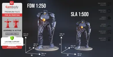
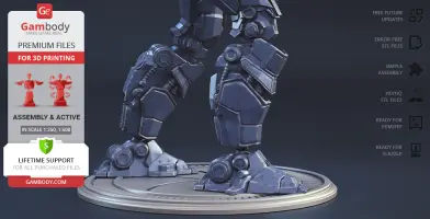
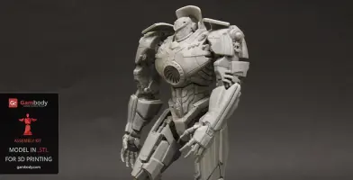
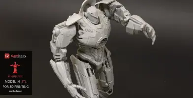
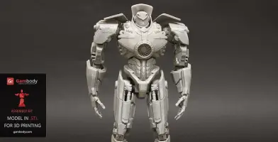
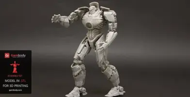
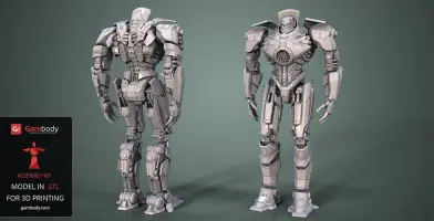
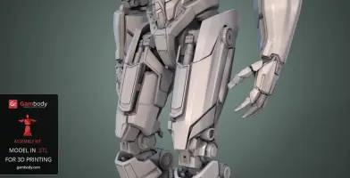
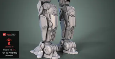
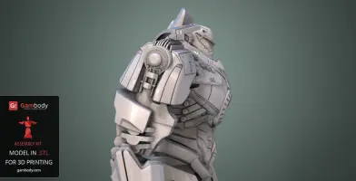
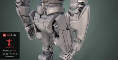
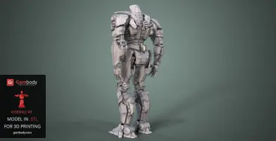
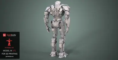
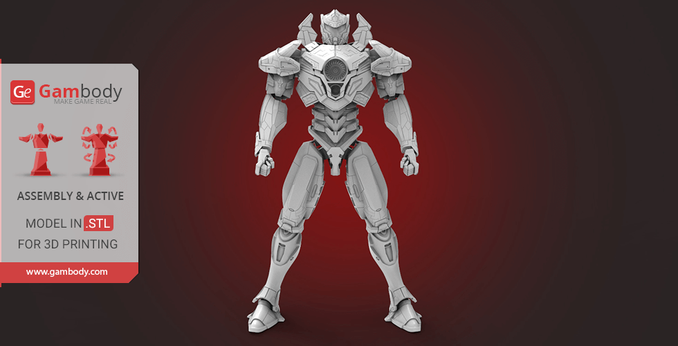
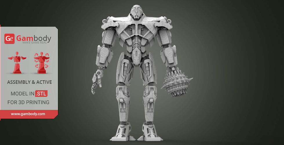
This 3D Model of Jaeger Gipsy Danger from Pacific Rim consists of files in StereoLithography (.Stl) format that is optimized for 3D printing.
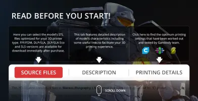
Before printing the files, we strongly recommend reading the PRINTING DETAILS section.
WHAT WILL YOU GET AFTER PURCHASE?
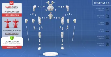
- FFF/FDM: 315 mm tall, 196 mm wide, 204 mm deep;
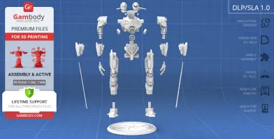
- DLP/SLA: 158 mm tall, 98 wide, 102 mm deep;
Detailed information about this 3D printing model is available in the DESCRIPTION section.

|
|||||
|---|---|---|---|---|---|
| File Name | File Size | Time / Filament | Object Size (x/y/z mm) |
||
|
1 (repaired).stl |
50.52 MiB | 11 h 57 min 6 m | 77 x 58 x 71 | Download | |
|
10 (repaired).stl |
0.40 MiB | 30 min <1 m | 28 x 14 x 31 | Download | |
|
11 (repaired).stl |
0.40 MiB | 30 min <1 m | 28 x 14 x 31 | Download | |
|
12 (repaired).stl |
14.08 MiB | 4 h 25 min 3 m | 26 x 45 x 72 | Download | |
|
13 (repaired).stl |
14.08 MiB | 4 h 25 min 2 m | 26 x 45 x 72 | Download | |
|
14 (repaired).stl |
3.54 MiB | 1 h 60 min 1 m | 35 x 65 x 22 | Download | |
|
15 (repaired).stl |
3.70 MiB | 1 h 60 min 1 m | 35 x 65 x 22 | Download | |
|
2 (repaired).stl |
21.25 MiB | 5 h 46 min 3 m | 45 x 44 x 57 | Download | |
|
3 (repaired).stl |
3.54 MiB | 47 min <1 m | 19 x 24 x 25 | Download | |
|
4 (repaired).stl |
13.11 MiB | 3 h 44 min 2 m | 64 x 36 x 32 | Download | |
|
5 (repaired).stl |
13.12 MiB | 3 h 44 min 2 m | 63 x 36 x 32 | Download | |
|
6 (repaired).stl |
11.74 MiB | 3 h 22 min 2 m | 30 x 28 x 72 | Download | |
|
7 (repaired).stl |
11.33 MiB | 3 h 24 min 2 m | 30 x 28 x 72 | Download | |
|
8 (repaired).stl |
12.31 MiB | 6 h 49 min 4 m | 28 x 50 x 92 | Download | |
|
9 (repaired).stl |
12.30 MiB | 6 h 50 min 4 m | 28 x 50 x 92 | Download | |
|
1_v2_hollow_body (repaire d).stl |
22.95 MiB | 16 h 20 min 8 m | 77 x 58 x 71 | Download | |
|
1_v2_reactor (repaired).s tl |
0.70 MiB | 15 min <1 m | 17 x 17 x 6 | Download | |
| ... | |||||
This should take overall.
ABOUT THIS 3D MODEL
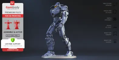
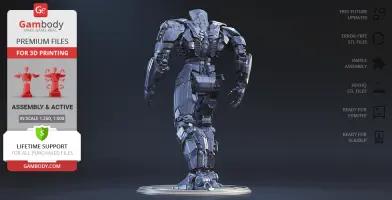
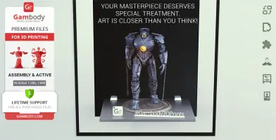
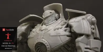
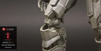
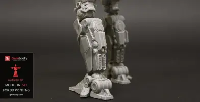
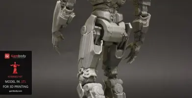
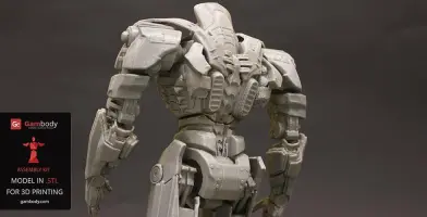
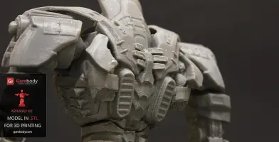
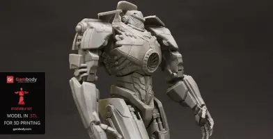
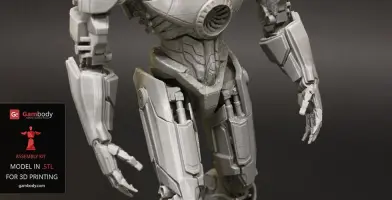
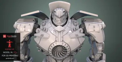
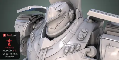
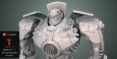
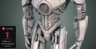
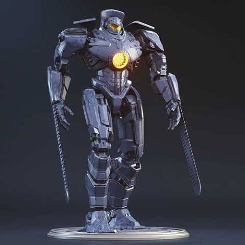
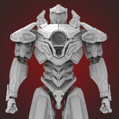
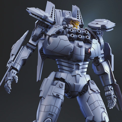
Gipsy Danger from Pacific Rim is an active Jaeger tasked with defending the coastline of Alaska. Being built on Kodiak Island, the Jaeger participated in the first mission on 17 October 2017. It then had subsequently participated in numerous combats against the Kaiju. The heavy combat machine is operated by two pilots. It is equipped with S-11 Pulse Launcher which fires a black matter that tends to disrupt the molecular structure of Kaiju biology.
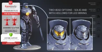
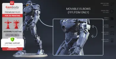
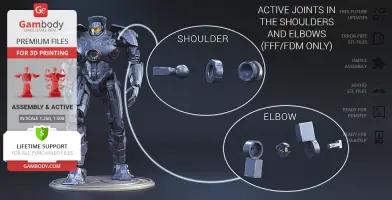
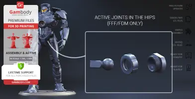
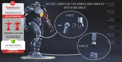
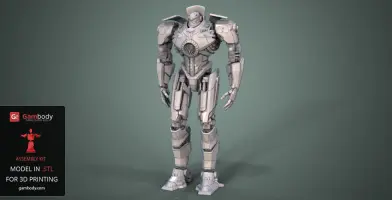
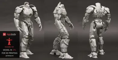
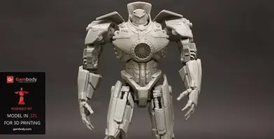
The new, updated version of Gipsy Danger will definitely get your praise! The model is presented in new scales, 1:250 in FFF/FDM and 1:500 in DLP/SLA. The better, high-poly design of Gipsy Danger ensures very detailed, intricate printing results. The hollowed parts of the model give the option to illuminate the Jeager using LED lights. Another stunning detail is the chain swords, which indeed make the mobile weapon so “danger”. The articulation of the new 2.0 version is provided by new, more secure, and durable joints. Be the first to enjoy the Gipsy Danger at completely higher level!
ADAPTATION FOR 3D PRINTING
Gipsy Danger for 3D printing is a fully active assembly model and its moderation and adaptation for different types of 3D printers took the Gambody team 51 hours in total.
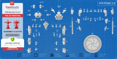
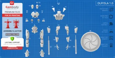
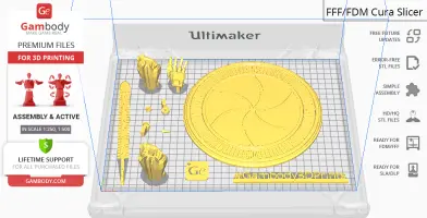
For you to receive the cleanest 3D printing result possible, minimize the amount of filament needed for generated support, and make use of the active elements designed by Gambody Engineers, the Jaeger was divided into convenient assembly parts.
All assembly parts in the FFF/FDM 2.0 version are provided in STL files in recommended positions that were worked out in order to ensure the smoothness of the details’ surfaces after printing and that the 3D printing beginners won’t face difficulties when placing the parts on a build plate. When downloading any model’s file you will also receive “Assembly Manual” for FFF/FDM 2.0 and DLP/SLA 1.0 versions in PDF format. We highly recommend that you get acquainted with the “Assembly Video” and “Assembly Manual” before getting down to the Gipsy Danger model.
The model is saved in STL files, a format supported by most 3D printers. All STL files for 3D printing have been checked in Netfabb and no errors were shown.
The model’s scale was calculated from the length of the Gipsy Danger which is 79 250 mm. The 3D printing model’s chosen scales are 1:250 for the FFF/FDM version and 1:500 for the DLP/SLA version.
VERSIONS’ SPECIFICATIONS
FFF/FDM 2.1 version features:
DLP/SLA 1.0 version features:
FFF/FDM 1.0 version features:
DLP/SLA ( Old version) Pre-Supported version features:
You can get the model of Gipsy Danger for 3D Printing immediately after the purchase! Just click the green Buy button in the top-right corner of the model’s page. You can pay with PayPal or your credit card.
Watch the tutorial on how to assemble Gipsy Danger 3D Printing Model on Gambody YouTube channel.
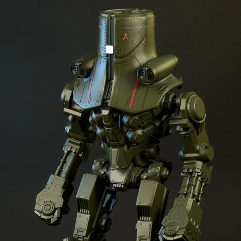
Also, you may like the Striker Eureka and Atlas Destroyer 3D Printing Models, and other Pacific Rim models and figurines for 3D Printing.
FAQ:
Below you can find printing recommendations for Cura, Simplify3D, Slic3r and PrusaSlicer software.
These are basic settings that were tested in Cura 4.8.0 slicer.
The test models were printed on Ultimaker 2, Creality Ender 3, Creality CR-10S Pro V2, Anycubic I3 Mega, Anycubic I3 MegaS 3D printers with PLA and PETG filaments.
Disclaimer: The following printing settings are a recommendation, not an obligation. The parameters can vary depending on the peculiarities of your 3D printer, the material you use and especially the particular assembly part at hand. Each part that any model comprises often needs preliminary review and you are free to tweak the settings the way you find suitable.
Note:
- You can scale up the model (downscaling is not recommended!);
- All connectors should be printed at 100% Infill;
- For all parts of locks (“ge_lock” in “Source files”) you need to change "Brim" type to "Skirt" in Build Plate Adhesion section.
Quality
Layer Height: 0.12 mm (you can also set Layer Height at 0.16 or 0.2mm for 0.4mm nozzles)
Initial Layer Height: 0.2 mm (carefully level the print bed and keep your Initial Layer Height the same as the main Layer Height)
Line Width: 0.4 mm
Wall Line Width: 0.4 mm
Outer Wall Line Width: 0.4 mm
Inner Wall(s) Line Width: 0.4 mm
Top/Bottom Line Width: 0.4 mm
Infill Line Width: 0.4 mm
Skirt/Brim Line Width: 0.4 mm
Support Line Width: 0.4 mm
Initial Layer Line Width: 100%
Shell
Wall Thickness: 0.8 mm
Wall Line Count: 2
Outer Wall Wipe Distance: 0.3 mm
Top Surface Skin Layers: 0
Top/Bottom Thickness: 0.6 mm
Top Thickness: 0.6 mm
Top Layers: 5
Bottom Thickness: 0.6 mm
Bottom Layers: 5
Initial Bottom Layers: 5
Top/Bottom Pattern: Lines
Bottom Pattern Initial Layer: Lines
Top/Bottom Line Directions: [ ]
Outer Wall Inset: 0 mm
Optimize Wall Printing Order: Check
Compensate Wall Overlaps: Check
Compensate Inner Wall Overlaps: Check
Minimum Wall Flow: 0%
Fill Gaps Between Walls: Everywhere
Filter Out Tiny Gaps: Check
Horizontal Expansion: 0 mm
Initial Layer Horizontal Expansion: 0 mm
Hole horizontal expansion: 0
Z Seam Alignment: User Specified
Z Seam Position: Back
Z Seam X: Average length of your printer’s plate (e.g.”150” if your plate is 300mm on the X-axis)
Z Seam Y: A value higher than the length of your plate on the Y-axis (e.g. 700)
Seam Corner Preference: Hide Seam
Extra Skin Wall Count: 1
Skin Overlap Percentage: 10%
Skin Overlap 0.04 mm
Infill
Infill Density: 20% (for all smaller parts and for all parts of connectors use 100% Infill)
Infill Pattern: Triangles
Connect Infill Lines: Check
Infill Line Directions: [ ]
Infill X Offset: 0 mm
Infill Y Offset: 0 mm
Infill Line Multiplier: 1
Extra Infill Wall Count: 0
Infill Overlap Percentage: 10-20%
Infill Overlap: 0.04 mm
Skin Overlap Percentage: 5%
Skin Overlap: 0.02 mm
Infill Wipe Distance: 0 mm
Infill Layer Thickness: 0.24 mm
Gradual Infill Steps: 0
Infill Before Walls: Check
Minimum Infill Area: 0 mm2
Skin Removal Width: 0.8 mm
Top Skin Removal Width: 0.8 mm
Bottom Skin Removal Width: 0.8 mm
Skin Expand Distance: 0.8
Top Skin Expand Distance: 0.8
Bottom Skin Expand Distance: 0.8
Maximum Skin Angle for Expansion: 90˚
Minimum Skin Width for Expansion: 0.0
Skin Edge Support Thickness: 0
Skin Edge Support Layers: 0
Material
Initial Layer Flow: 100%
Printing Temperature: See your filament settings
Initial Printing Temperature: Your filament settings
Final Printing Temperature: Your filament settings
Build Plate Temperature: Your filament settings
Build Plate Temperature Initial Layer: Your filament settings + 5°
Flow: 100% (Important! If you face difficulty printing the model, you may need to adjust the Flow parameter. You may research the topic using the Internet or seek assistance at our Customer Support Team at support@gambody.com)
Speed
You can increase the printing Speed by 20% when you print simple objects. For small/thin parts you need to decrease the Speed by 25% - 50%.
Print Speed: 50 mm/s
Infill Speed: 50 mm/s
Wall Speed: 25 mm/s
Outer Wall Speed:25 mm/s
Inner Wall Speed: 50 mm/s
Top/Bottom Speed: 25mm/s
Support Speed: 25 mm/s
Support Infill Speed: 45 mm/s
Support Interface Speed: 25 mm/s
Support Roof Speed: 25 mm/s
Support Floor Speed: 25 mm/s
Travel Speed: 80 mm/s
Initial Layer Speed: 80 mm/s
Initial Layer Print Speed: 20 mm/s
Initial Layer Travel Speed: 80 mm/s
Skirt/Brim Speed: 20 mm/s
Z Hop Speed: 5 mm/s
Number of Slower Layers: 2
Enable Acceleration Control: Check
When printing simple objects, you need to set all Acceleration parameters at 500 mm/s. For small/thin parts you need to decrease the Acceleration by 50% - 70%.
Travel
Enable Retraction: Check
Retraction Distance: 4-8 mm, 1-3 mm for Direct Extruder (This is the most important retraction parameter. You can find your optimal value of Retraction Distance by printing any test object, e.g. bridges, towers etc.)
Retraction Speed: 25mm/s
Retraction Retract Speed: 25 mm/s
Retraction Prime Speed: 25 mm/s
Retraction Extra Prime Amount: 0 mm3
Retraction Minimum Travel: 1.5 mm
Maximum Retraction Count: 100
Minimum Extrusion Distance Window: 6,5 - 10 mm
Limit Support Retractions: Check
Combing Mode: All
Max Comb Distance With No Retract: 30 mm
Retract Before Outer Wall: Check
Avoid Printed Parts When Travelling: Check
Avoid Supports When Travelling: Check
Travel Avoid Distance: 1 mm
Layer Start X: 0.0 mm
Layer Start Y: 0.0 mm
Z Hop When Retracted: Check
Z Hop Height: 0,3 mm
Cooling
Enable Print Cooling: Check
Fan Speed: 100%
Regular Fan Speed: 100%
Maximum Fan Speed: 100%
Regular/Maximum Fan Speed Threshold: 10 s
Initial Fan Speed: 0%
Regular Fan Speed at Height: 0.36 mm
Regular Fan Speed at Layer: 3
Minimum Layer Time: 10 s
Minimum Speed: 10 mm/s
Support
Generate Support: Check
Support Structure: Normal (you can try using Tree Support Structure if you have difficulty printing any particular assembly part)
Support Placement: Everywhere
Support Overhang Angle: 60° (this parameter can range from 30° to 70° depending on the part at hand)
Support Pattern: Zig Zag
Support Wall Line Count: 1 (stronger support that might be more difficult to remove) 0 (less strong support but is easier to remove)
Support Density: 15%
Support Line Distance: 2.6667 mm
Initial layer support line distance: 2.667 mm
Support Z Distance: 0.12 mm
Support Top Distance: 0.12 mm
Support Bottom Distance: 0.12 mm
Support X/Y Distance: 0.8-1 mm
Support Distance Priority: Z overrides X/Y
Support Stair Step Height: 0.3 mm
Support Stair Step Maximum Width: 5.0 mm
Support Stair Step Minimum Slope Angle: 10°
Support Join Distance: 2.0 mm
Support Horizontal Expansion: 0.2 mm
Support Infill Layer Thickness: 0.2 mm
Gradual Support Infill Steps: 0
Minimum Support Area: 2 mm
Enable Support Interface: Check (generates additional “pillow” on the support structure that leads to a more even surface, but can be difficult to remove in hard-to-reach areas)
Enable Support Roof: Check
Enable Support Floor: Check
Support Interface Thickness: 0.8 mm
Support Roof Thickness: 0.8 mm
Support Floor Thickness: 0.8 mm
Support Interface Resolution 0.2 mm
Support Interface Density: 50-100%
Support Roof Density: 50-100%
Support Roof Line Distance: 0.8 mm
Support Floor Density: 50-100%
Support Floor line Distance: 0.4mm
Support Interface Pattern: Grid
Support Roof Pattern: Grid (this parameter should differ from Bottom Pattern Initial Layer in “Shell” section)
Support Floor Pattern: Grid
Minimum Support Interface Area: 10mm
Minimum Support Roof Area: 10 mm
Minimum Support Floor Area: 10 mm
Support Interface Horizontal Expansion: 0.0 mm
Support Roof Horizontal Expansion: 0.0 mm
Support Floor Horizontal Expansion: 0.0 mm
Fan Speed Override: Check
Supported Skin Fan Speed: 100%
Use Towers: Check
Tower Diameter: 4 mm
Minimum Diameter: 3.0 mm
Tower Roof Angle: 65°
Build Plate Adhesion
Build Plate Adhesion Type: Skirt/Brim (For unsteady parts, and those parts that may come unstuck use “Brim”. For bigger assembly parts that have large adhesion area and for all parts of locks and claws that you want to come out clean use "Skirt")
Skirt/Brim Minimum Length: 250 mm
Brim Width: 8.0 mm
Brim Line Count: 10
Brim Only on Outside: Check
Mesh Fixes
Union Overlapping Volumes: Check
Merged Meshes Overlap: 0.15 mm
Special Modes
Print Sequence: All at Once
Surface Mode: Normal
Experimental
Slicing Tolerance: Middle
Maximum Resolution: 0.01 mm
Flow rate compensation max extrusion offset: 0 mm
Flow rate compensation factor: 100%
This model was tested with PLA material.
To avoid printing problems, we recommend the following settings:
Extruder
Nozzle Diameter: 0.4 mm
Extrusion Multiplier: 0.97
Extrusion Width: Auto
Retraction Distance: 5.00 mm
Extra Restart Distance: 0.00 mm
Retraction Vertical Lift: 0.08 mm
Retraction Speed: 5400.0 mm/min
Wipe Distance: 5.00 mm
Layer
Primary Layer Height: 0.2 mm
Top Solid Layers: 8
Bottom Solid Layers: 5
Outline/Perimeter Shells: 2
Outline Direction: Inside-Out
First Layer Height: 90%
First Layer Width: 100%
First Layer Speed: 20%
Additions
Use Skirt/Brim: Check
Skirt Layers: 1
Skirt Offset from Part: 6.00 mm
Skirt Outlines: 5
Infill
Internal Fill Pattern: Fast Honeycomb
External Fill Patern: Rectilinear
Interior Fill Percentage: 10%
Outline Overlap: 22%
Infill Extrusion Width: 100%
Minimum Infill Length: 5.00 mm
Combine Infill Every: 1 layers
External Infill Angle Offsets: 45/-45 deg
Support
Generate Support Material: Check
Support Infill Percentage: 15%
Extra Inflation Distance: 1.00 mm
Support Base Layers: 0
Combine Support Every: 1 layers
Dense Support Layers: 0
Dense Infill Percentage: 70%
Support Type: Normal
Support Pillar Resolution: 5.00 mm
Max Overhang Angle: 60 deg
Horizontal Offset From Part: 0.50 mm
Upper Vertical Separation Layers: 1
Lower Vertical Separation Layers: 1
Support Infill Angles: 45 deg
Temperature
Extruder 1 Temperature: 210
Heated Bed: 60
Cooling
Increase fan speed for layers below: 45.0 sec
Maximum Cooling fan speed: 50%
Bridging fan speed override: 100%
Speeds
Default Printing Speed: 4800.0 mm/min
Outline Underspeed: 50%
Solid Infill Underspeed: 80%
Support Structure Underspeed: 80%
X/Y Axis Movement Speed: 10800.0 mm/min
Z Axis Movemen Speed: 1002.0 mm/min
Adjust printing speed for layers below: 15.0 sec
Allow speed reduction down to: 20%
Other
Unsupported area threshold: 20.0 sq m
These basic 3D printing settings recommendations for beginners were tested in Slic3r 1.3.0 software. Test models were printed on Ultimaker 2, Creality Ender 3, Creality Cr-10S pro v2, Anycubic I3 Mega, Anycubic I3 MegaS, Anycubic Vyper with PLA and PetG filaments.
Note:
- You can upscale your 3D printing models. Downscaling is not recommended - it can make smaller parts of the model unprintable, distort the model’s level of detail and result in assembly issues.
- All connectors should be printed at 100% Infill.
- When printing Lock connectors, we recommend setting the “Brim width” parameter to 0 in the "Skirt and Brim" print settings. In that way, the Locks will be 3D printed with a Skirt only.
Print Settings Tab
Layers and perimeters
Layer height:
Layer Height: 0.1-0.2
First layer height: 0.2-0.3
Vertical shells:
Perimeters: 2-3
Spiral vase: OFF
Horizontal shells:
Solid layers: 8 (For 0.1 Layer Height) or 4 (For 0.2 Layer Height)
Quality (slow slicing)
Extra perimeters if needed: CHECK
Avoid crossing perimeters: CHECK
Detect thin walls: -//-
Detect bridging perimeters: CHECK
Advanced:
Seam position: Aligned
External perimeters first: -//-
Infill
Fill Density: 10%
Fill Pattern: Rectilinear
Top Fill Pattern: Rectilinear
Bottom fill pattern: Rectilinear
Reducing printing time:
Combine infill every: 1
Only infill where needed: -//-
Advanced:
Fill gaps: CHECK
Solid Infill every: 0
Fill angle: 45
Solid Infill threshold area: 70
Bridging angle: 0
Only retract when crossing perimeters: CHECK
Infill before perimeters: -//-
Skirt and brim
Skirt
Loops (minimum): 3
Distance from Object: 5
Skirt Height: 1 ( for pla and petg)
Minimal Filament extrusion length: 50
Brim
Brim width: (5-8 mm is optional for small prints that have bad adhesion to the build plate)
Support material
Support Material:
Generate Support material: -//- (enable this parameter if your model requires supports)
Overhang threshold: 40-60
Enforce support for the first: 0
Raft:
Raft Layers: 0
Options for Support material and Raft:
Contact Z distance: 0.2
Pattern: Rectilinear
Pattern spacing: 2.5
Pattern angle: 0
Interface Layers: 3
Interface pattern spacing: 0.2
Support on build plate only: -//-
Don’t support bridges: CHECK
Speed
Speed for print movies
(We recommend that you try printing with the parameters listed below and then adjust the print speed until the printing quality is optimal for you)
Perimeters: 20 mm/s
Small perimeters: 20 mm/s
External perimeters: 20 mm/s
Infill: 50 mm/s
Solid: 30 mm/s
Top solid : 20 mm/s
Gaps: 20 mm/s
Bridges: 20 mm/s
Support material: 50 mm/s
Speed for non print movies
Travel: 100 mm/s
Modifiers
First layer speed: 10 mm/s
Acceleration control (Settings for advanced users, change these parameters only if you have sufficient 3D printing expertise)
Perimeters: 400 mm/s2
Infill: 400 mm/s2
Bridge: 400 mm/s2
First layer: 300 mm/s2
Default: 400 mm/s2
Auto speed (advanced)
Max print speed: 100 mm/s
Max volumetric speed: 0 mm3/s
Multiple Extruders
These settings only work for 3D printers with multiple extruders (not recommended for beginners)
Advanced
Extrusion width
You can try setting all parameters in this section, except the First layer, to values between 0.75% of your nozzle diameter and 1.25% of your nozzle diameter. Adjusting them will help you work out the optimal parameters for the best quality for your print. As for the First layer, you can set it to 150% of the diameter of your nozzle for better adhesion to the build plate (for a nozzle with a diameter of 0.4 mm, the First layer extrusion width can be from 0.3 mm to 0.5 mm)
Overlap
Infill/perimeters overlap: 25%
Flow
Bridge flow ratio: 0.7
Other
-//-
Output options
-//-
Notes
-//-
Shortcuts
-//-
Filament Settings Tab
Filament
Filament
Color: -//-
Diameter: 1.75
Extrusion multiplier: 1
Density: -//-
Cost: -//-
(You can set these parameters yourself if you need)
Cooling
Enable
Keep fan always on: CHECK
Enable auto cooling: -//-
Fan settings
Fan speed
Min: 100% (for PLA, PETG) or 30% (for ABS, SBS)
Max: -//-
Bridges fan speed: 100%
Disable fan for the first: 1
Cooling thresholds
Enable fan if layer print time is below: -//-
Slow down if layer print time is below: -//-
Min print Speed: -//-
Custom G-code
-//-
Notes
-//-
Printer Settings Tab
General
Size and coordinates
Bed shape: your 3D printer’s bed size
Z offset: 0
Capabilities
Extruders: 1
Has heated bed: CHECK
Firmware
G-code flavor: RepRap (Marlin/Sprinter)
Advanced
Use relative E distances: CHECK
Custom G-code
Use your 3D printer’s standard G-code. If you don't have it, you may use the example below.
Start G-code
M104 S(First_layer_temperature)
M140 S(First_layer_bed_temperature)
G28 S(Parking)
M109 S(waiting_for_warm-up_nozzle)
M190 S(waiting_for_warm-up_bed)
End G-code
M104 s0 ;turn off nozzle
M140 s0 ;turn off bed
G91
G1 Z1
G28 X0 Y0 ;park
M84 ;disable motors
M107 ;disable cooling
Extruder 1
Size
Nozzle diameter: 0.4 mm
Layer height limits
Min: 0.05
Max: 0.3
Position
Extruder offset: -//-
Retraction
Length: 5.5-6.5 mm (1mm for a direct extruder)
Lift Z: 0-0.3 mm
Speed: 30 - 40 mm/s
Extra length on restart: 0 mm
Minimum travel after retraction: 2 mm
Retract on layer change: -//- (you can try to enable this parameter)
Wipe while retracting: -//- (you can try to enable this parameter)
These basic 3D printing settings recommendations for beginners were tested in PrusaSlicer 2.3.1. Test models were printed on Ultimaker 2, Creality Ender 3, Creality Cr-10S pro v2, Anycubic I3 Mega, Anycubic I3 MegaS, Anycubic Vyper with PLA and PETG filaments.
Note:
- You can upscale your 3D printing models. Downscaling is not recommended - it can make smaller parts of the model unprintable, distort the model’s level of detail and result in assembly issues.
- All connectors should be printed at 100% Infill.
- When printing Lock connectors, we recommend setting the “Brim width” parameter to 0 in the "Skirt and Brim" print settings. In that way, the Locks will be 3D printed with a Skirt only.
In order to see all the parameters listed below, you need to enable the Expert mode in the PrusaSlicer’s settings.
Print Settings Tab
Layers and perimeters
Layer height:
Layer Height: 0.1-0.2
First layer height: 0.2-0.3
Vertical shells:
Perimeters: 2-3
Spiral vase: OFF
Horizontal shells:
Solid layers: 8 (for 0.1 Layer Height) or 4 (for 0.2 Layer Height)
Minimum shell thickness: 0.8
Quality (slower slicing)
Extra perimeters if needed: CHECK
Ensure vertical shell thickness: -//-
Avoid crossing perimeters: CHECK
Detect thin walls: -//-
Detect bridging perimeters: CHECK
Advanced:
Seam position: Aligned
External perimeters first: -//-
Infill
Infill
Fill Density: 10%
Fill Pattern: Rectilinear
Top Fill Pattern: Monotonic
Bottom fill pattern: Monotonic
Reducing printing time:
Combine infill every: 1
Only infill where needed: -//-
Advanced:
Solid Infill every: 0
Fill angle: 45
Solid Infill threshold area: 70
Bridging angle: 0
Only retract when crossing perimeters: CHECK
Infill before perimeters: -//-
Skirt and brim
Skirt
Loops (minimum): 3
Distance from Object: 5
Skirt Height: 1 (for PLA and PETG)
Draft Shield: -//-
Minimal filament extrusion length: 50
Brim
Brim width: (5-8 mm is optional for small prints that have bad adhesion to the build plate)
Support material
Support Material:
Generate Support material: -//- (enable this parameter if your model requires supports)
Auto generated supports: CHECK
Overhang threshold: 40-60
Enforce support for the first: 0
Raft:
Raft Layers: 0
Options for Support material and Raft:
Contact Z distance: 0.2
Pattern: Rectilinear
With sheath around the support: CHECK
Pattern spacing: 2.5
Pattern angle: 0
Interface Layers: 3
Interface pattern spacing: 0.2
Interface loops: -//-
Support on build plate only: -//-
XY separation between an object and its support: 50%
Don’t support bridges: CHECK
Synchronize with object layers: -//-
Speed
Speed for print moves
(We recommend that you try printing with the parameters listed below and then adjust the print speed until the printing quality is optimal for you)
Perimeters: 20 mm/s
Small perimeters: 20 mm/s
External perimeters: 20 mm/s
Infill: 50 mm/s
Solid infill: 30 mm/s
Top solid infill: 20 mm/s
Support material: 50 mm/s
Support material interface: 20 mm/s
Bridges: 20 mm/s
Gap fill: 20 mm/s
Ironing: 15 mm/s
Speed for non-print moves
Travel: 100 mm/s
Modifiers
First layer speed: 10 mm/s
Acceleration control (Settings for advanced users, change these parameters only if you have sufficient 3D printing expertise)
Perimeters: 400 mm/s2
Infill: 400 mm/s2
Bridge: 400 mm/s2
First layer: 400 mm/s2
Default: 400 mm/s2
Auto speed (advanced)
Max print speed: 100 mm/s
Max volumetric speed: 0 mm3/s
Multiple Extruders
These settings only work for 3D printers with multiple extruders (not recommended for beginners)
Advanced
Extrusion width
You can try setting all parameters in this section, except the First layer, to values between 0.75% of your nozzle diameter and 1.25% of your nozzle diameter. Adjusting them will help you work out the optimal parameters for the best quality for your print. As for the First layer, you can set it to 150% of the diameter of your nozzle for better adhesion to the build plate (for a nozzle with a diameter of 0.4 mm, the First layer extrusion width can be from 0.3 mm to 0.5 mm)
Overlap
Infill/perimeter overlap: 25%
Flow
Bridge flow ratio: 0.7
Slicing
-//-
Other
Clip multi-part objects: CHECK
Output options
-//-
Notes
-//-
Dependencies
-//-
Filament Settings Tab
Filament
Filament
Color: -//-
Diameter: 1.75
Extrusion multiplier: 1
Density: -//-
Cost: -//-
Spool weight: -//-
(You can set these parameters yourself if you need)
Temperature
Сheck your filament manufacturer's temperature recommendations on the spool.
Cooling
Enable
Keep fan always on: CHECK
Enable auto cooling: -//-
Fan settings
Fan speed
Min: 100% (for PLA, PETG) or 30% (for ABS, SBS)
Max: -//-
Bridges fan speed: 100%
Disable fan for the first: 1
Full fan speed at layer: 3-4
Cooling thresholds
Enable fan if layer print time is below: -//-
Slow down if layer print time is below: -//-
Min print speed: -//-
Advanced
Print speed override
Max volumetric speed:
PLA: 14 MM3/S
ABS: 10 MM3/S
PETG: 14 MM3/S
HIPS: 10 MM3/S
(If you use the Volcano extruder for your printer, all parameters need to be increased x2)
Filament Overrides
-//-
Custom G-code
-//-
Notes
-//-
Dependencies
-//-
Printer Settings Tab
General
Size and coordinates
Bed shape: your 3D printer’s bed size
Max print height: your 3D printer’s height
Z offset: 0
Capabilities
Extruders: 1
Single Extruder Multi Material: -//-
Firmware
G-code flavor: RepRap/Sprinter
G-code thumbnails: -//-
Supports stealth mode: -//-
Supports remaining times: -//-
Advanced
Use relative E distances: CHECK
Use firmware retraction: -//- (needs to be enabled in the firmware of your printer)
Use volumetric E: -//-
Enable variable layer height feature: CHECK
Custom G-code
Use your 3D printer’s standard G-code. If you don't have it, you may use the example below.
Start G-code
M104 S(First_layer_temperature)
M140 S(First_layer_bed_temperature)
G28 S(Parking)
M109 S(waiting_for_warm-up_nozzle)
M190 S(waiting_for_warm-up_bed)
End G-code
M104 s0 ;turn off nozzle
M140 s0 ;turn off bed
G91
G1 Z1
G28 X0 Y0 ;park
M84 ;disable motors
M107 ;disable cooling
Extruder 1
Size
Nozzle diameter: 0.4 mm
Layer height limits
Min: 0.05
Max: 0.3
Position
Extruder offset: -//-
Retraction
Length: 5.5-6.5 mm (1 mm for a direct extruder)
Lift Z: 0-0.3 mm
Retraction Speed: 30 - 40 mm/s
Deretraction Speed: 0 mm/s
Extra length on restart: 0 mm
Minimum travel after retraction: 2 mm
Retract on layer change: -//- (you can try to enable this parameter)
Wipe while retracting: -//- (you can try to enable this parameter)
Retract amount before wipe:
Notes
-//-
Dependencies
-//-
robot, robots, presupported, kaiju, bf, warrior, pacific-rim, jaeger, pacificrim, world-war
You are about to report Gipsy Danger 3D Printing Model | Assembly + Active for violating our Terms and Conditions. Please take a few moments to fill in the following information.


Comments
comments powered by Disqus