


This should take overall.

• Looking for an exact name? Put it in quotes:
• Want models from a specific author? Use @:
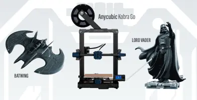
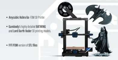
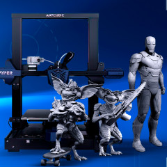
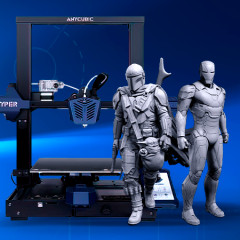
This bundle consists of DIYAnycubic Kobra Go FDM 3D Printer, LordDarth Vader 3D Printing Figurine and Batwing 1989 3D Printing Model. The 3D printing models comprise the files in StereoLithography (.STL) format that is optimized for FFF/FDM 3D printing.
WHAT WILL YOU GET AFTER PURCHASE?
- New Auto-Levelling DIY FDM 3D Printer Kobra Go by Anycubic
- STL files of Darth Vader for FFF/FDM printing:
Files are available for download immediately after purchase
- STL files of Batwing 1989 for FFF/FDM printing:
Files are available for download immediately after purchase
- Printing settings for Cura 5.2.1 that we provide as a recommendation for Anycubic Kobra Go FDM 3D Printer
- Full technical support from the Gambody Support Team
Detailed information about this bundle is available in the DESCRIPTION section.
 | |||||
|---|---|---|---|---|---|
| File Name | File Size | Time / Filament | Object Size (x/y/z mm) | ||
| _1_body_beams_x46_FDM (re paired).stl | 0.01 MiB | 6 min <1 m | 20 x 5 x 5 | Download | |
| _2_body_front_a_FDM (repa ired).stl | 31.31 MiB | 10 h 46 min 6 m | 95 x 42 x 103 | Download | |
| _3_body_front_a_cap_FDM ( repaired).stl | 1.70 MiB | 20 min <1 m | 29 x 12 x 21 | Download | |
| _4_body_front_b_FDM (repa ired).stl | 27.49 MiB | 44 h 42 min 26 m | 108 x 86 x 147 | Download | |
| _5_body_front_b_cap_FDM ( repaired).stl | 0.08 MiB | 16 min <1 m | 14 x 13 x 14 | Download | |
| _6_body_back_R_FDM (repai red).stl | 23.99 MiB | 50 h 9 min 30 m | 138 x 100 x 220 | Download | |
| _7_body_back_L_FDM (repai red).stl | 23.99 MiB | 49 h 31 min 30 m | 138 x 100 x 220 | Download | |
| _8_body_wing_a_R_FDM (rep aired).stl | 10.78 MiB | 10 h 21 min 6 m | 83 x 38 x 110 | Download | |
| _9_body_wing_a_L_FDM (rep aired).stl | 10.78 MiB | 10 h 20 min 6 m | 83 x 38 x 110 | Download | |
| _10_body_wing_b_R_FDM (re paired).stl | 11.45 MiB | 17 h 58 min 10 m | 159 x 15 x 194 | Download | |
| _11_body_wing_b_L_FDM (re paired).stl | 11.45 MiB | 18 h 10 min 10 m | 159 x 15 x 194 | Download | |
| _12_body_wing_c_R_FDM (re paired).stl | 12.11 MiB | 20 h 28 min 11 m | 137 x 18 x 217 | Download | |
| _13_body_wing_c_L_FDM (re paired).stl | 12.11 MiB | 20 h 48 min 11 m | 137 x 18 x 217 | Download | |
| _14_flap_R_FDM (repaired) .stl | 0.06 MiB | 52 min 1 m | 48 x 45 x 6 | Download | |
| _15_flap_L_FDM (repaired) .stl | 0.06 MiB | 52 min 1 m | 48 x 45 x 6 | Download | |
| _16_gun_R_FDM (repaired). stl | 0.38 MiB | 30 min <1 m | 6 x 6 x 61 | Download | |
| _17_gun_L_FDM (repaired). stl | 0.38 MiB | 30 min <1 m | 6 x 6 x 61 | Download | |
| _18_wing_small_top_R_FDM (repaired).stl | 1.78 MiB | 3 h 11 min 2 m | 40 x 108 x 81 | Download | |
| _19_wing_small_top_L_FDM (repaired).stl | 1.78 MiB | 3 h 10 min 2 m | 40 x 108 x 81 | Download | |
| _20_wing_small_top_mid_FD M (repaired).stl | 0.95 MiB | 21 min <1 m | 4 x 27 x 21 | Download | |
| _21_wing_small_bot_R_FDM (repaired).stl | 1.11 MiB | 56 min 1 m | 25 x 46 x 42 | Download | |
| _22_wing_small_bot_L_FDM (repaired).stl | 1.11 MiB | 55 min 1 m | 25 x 46 x 42 | Download | |
| _23_rockets_x4_FDM (repai red).stl | 0.13 MiB | 12 min <1 m | 5 x 5 x 24 | Download | |
| _24_wing_window_R_FDM (re paired).stl | 0.30 MiB | 14 min <1 m | 16 x 10 x 15 | Download | |
| _25_wing_window_L_FDM (re paired).stl | 0.30 MiB | 14 min <1 m | 16 x 10 x 15 | Download | |
| _26_window_a_FDM (repaire d).stl | 3.98 MiB | 1 h 46 min 1 m | 55 x 33 x 45 | Download | |
| _27_window_b_FDM (repaire d).stl | 5.53 MiB | 4 h 18 min 2 m | 59 x 48 x 94 | Download | |
| _28_machine_gun_R_FDM (re paired).stl | 1.69 MiB | 1 h 53 min 1 m | 15 x 11 x 65 | Download | |
| _29_machine_gun_L_FDM (re paired).stl | 1.69 MiB | 1 h 46 min 1 m | 15 x 11 x 65 | Download | |
| _30_saw_a_FDM (repaired). stl | 0.19 MiB | 56 min 1 m | 25 x 92 x 8 | Download | |
| _31_saw_b_R_FDM (repaired ).stl | 0.09 MiB | 7 min <1 m | 7 x 39 x 3 | Download | |
| _32_saw_b_L_FDM (repaired ).stl | 0.09 MiB | 7 min <1 m | 7 x 39 x 3 | Download | |
| _33_cockpit_main_FDM (rep aired).stl | 2.99 MiB | 13 h 7 min 9 m | 54 x 139 x 54 | Download | |
| _34_cockpit_stearing_FDM (repaired).stl | 1.49 MiB | 26 min <1 m | 29 x 14 x 18 | Download | |
| _35_cockpit_pedals_FDM (r epaired).stl | 0.03 MiB | 13 min <1 m | 26 x 7 x 7 | Download | |
| _36_cockpit_seat_FDM (rep aired).stl | 1.19 MiB | 5 h 35 min 3 m | 39 x 55 x 61 | Download | |
| _37_cockpit_visor_a_FDM ( repaired).stl | 0.24 MiB | 10 min <1 m | 12 x 33 x 6 | Download | |
| _38_cockpit_visor_b_FDM ( repaired).stl | 0.18 MiB | 6 min <1 m | 20 x 6 x 5 | Download | |
| _39_cockpit_luke_FDM (rep aired).stl | 0.05 MiB | 1 h 6 min 1 m | 45 x 56 x 3 | Download | |
| _40_chassis_front_b_FDM ( repaired).stl | 0.55 MiB | 27 min <1 m | 22 x 55 x 10 | Download | |
| _41_chassis_front_a_FDM ( repaired).stl | 0.93 MiB | 2 h 19 min 1 m | 44 x 53 x 22 | Download | |
| _42_chassis_front_wheel_x 2_FDM (repaired).stl | 1.12 MiB | 20 min <1 m | 19 x 19 x 9 | Download | |
| _43_chassis_a_R_FDM (repa ired).stl | 1.04 MiB | 6 h 18 min 4 m | 74 x 60 x 31 | Download | |
| _44_chassis_b_R_FDM (repa ired).stl | 0.46 MiB | 41 min <1 m | 19 x 62 x 13 | Download | |
| _45_chassis_wheel_R_FDM ( repaired).stl | 1.17 MiB | 36 min <1 m | 25 x 25 x 12 | Download | |
| _46_chassis_a_L_FDM (repa ired).stl | 1.04 MiB | 6 h 21 min 4 m | 74 x 60 x 31 | Download | |
| _47_chassis_b_L_FDM (repa ired).stl | 0.46 MiB | 41 min <1 m | 19 x 62 x 13 | Download | |
| _48_chassis_wheel_L_FDM ( repaired).stl | 1.17 MiB | 36 min <1 m | 25 x 25 x 12 | Download | |
| _49_chassis_cap_front_FDM (repaired).stl | 0.90 MiB | 1 h 14 min 1 m | 31 x 53 x 8 | Download | |
| _50_chassis_cap_R_FDM (re paired).stl | 0.27 MiB | 2 h 13 min 1 m | 45 x 60 x 11 | Download | |
| _51_chassis_cap_L_FDM (re paired).stl | 0.27 MiB | 2 h 13 min 1 m | 45 x 60 x 11 | Download | |
| _52_platform_1_FDM (repai red).stl | 5.30 MiB | 71 h 50 min 41 m | 199 x 190 x 46 | Download | |
| _53_platform_2_FDM (repai red).stl | 5.37 MiB | 70 h 31 min 41 m | 220 x 197 x 45 | Download | |
| _54_platform_3_FDM (repai red).stl | 4.44 MiB | 64 h 51 min 38 m | 184 x 181 x 45 | Download | |
| _55_platform_4_FDM (repai red).stl | 5.00 MiB | 64 h 28 min 38 m | 186 x 207 x 45 | Download | |
| _56_platform_5_FDM (repai red).stl | 5.87 MiB | 66 h 32 min 39 m | 195 x 176 x 47 | Download | |
| _57_platform_6_FDM (repai red).stl | 5.32 MiB | 68 h 30 min 40 m | 193 x 202 x 46 | Download | |
| _58_platform_7_FDM (repai red).stl | 5.10 MiB | 68 h 49 min 40 m | 187 x 216 x 45 | Download | |
| _59_platform_8_FDM (repai red).stl | 0.26 MiB | 74 h 51 min 75 m | 193 x 193 x 45 | Download | |
| _60_platform_cap_FDM (rep aired).stl | 0.07 MiB | 1 h 59 min 1 m | 28 x 27 x 44 | Download | |
| _61_platform_beam_a_FDM ( repaired).stl | 0.20 MiB | 4 h 57 min 3 m | 27 x 147 x 26 | Download | |
| _62_platform_beam_b_FDM ( repaired).stl | 0.34 MiB | 4 h 15 min 3 m | 42 x 26 x 147 | Download | |
| Keychain (repaired).stl | 0.35 MiB | 23 min <1 m | 30 x 30 x 2 | Download | |
| Tag (repaired).stl | 1.70 MiB | 1 h 18 min 1 m | 150 x 18 x 5 | Download | |
| ... | |||||
This should take overall.
ABOUT THIS BUNDLE
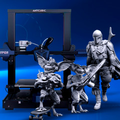
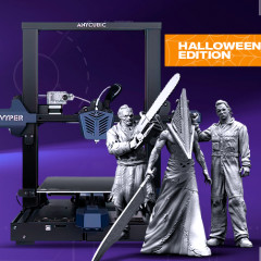
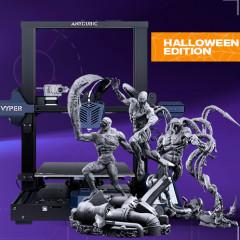
Gambody 3D Printing Marketplace and Anycubic 3D Printer Manufacturer have prepared another irresistible offer for 3D printing beginners and pros! As a part of the Gambody & Anycubic collaboration, we offer you a new set of bundles featuring the affordable DIY Auto-Levelling Kobra Go 3D Printer and high-quality 3D printing designs by Gambody contributors. Enjoy the reliable hobby 3D printing machine and top-notch STL files in one Go!
Please, find the details of the collaboration in our official Press Release.
IMPORTANT: On the Checkout page, you will see the ‘Shipping Information’ section where you will need to specify your shipping details. If you happen to have any questions or want to leave any notes, please contact us at support@gambody.com. Your shipping details will be delivered to Anycubic 3D printer manufacturer, who will take care of the Kobra Go 3D printer’s shipping and provide the tracking number. The delivery of the Kobra Go 3D printer may be expected approximately within 3 weeks after placing the order.
ABOUT THE 3D PRINTER
Kobra Go is a DIY 3D printer enhanced with Anycubic’s innovative features for your easy 3D printing process. After the assembly, you will be able to enjoy the self-developed Anycubic LeviQ auto-levelling system, abrasion-resistant spring steel build plate, separated Bowden extruder, smart power-off and filament supply sensors. Moreover, the 250 x 220 x 220 mm build volume of the compact 3D printer will be sufficient for your Gambody 3D printing projects and the dreams you would like to come to life!
You can read more about the printer's remarkable features on Anycubic’s official website and Gambody Team’s upcoming review.
ABOUT 3D PRINTING MODELS
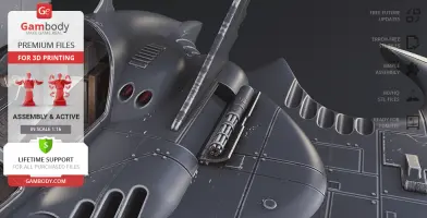
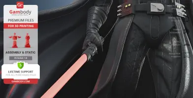
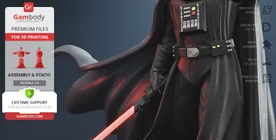
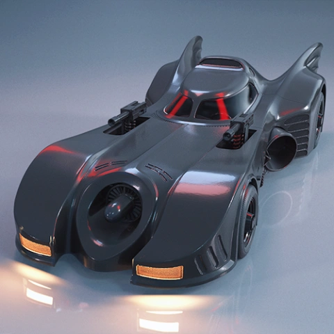
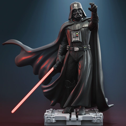
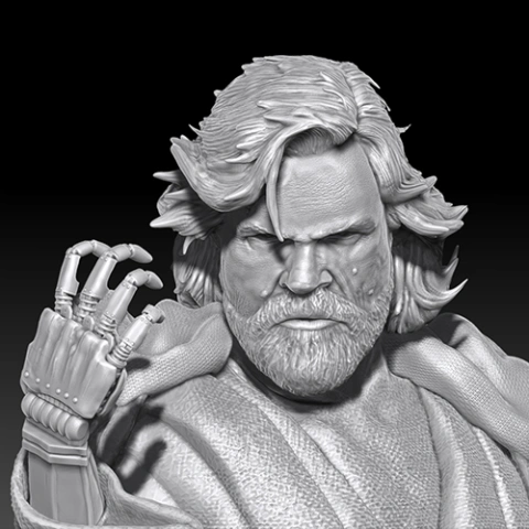
Lord Darth Vader and Batwing 1989 STL files are highly detailed 3D printing projects that were created by our talented contributing 3D artists and thoroughly moderated and adapted for 3D printing by Gambody team. This bundle comprises the FFF/FDM versions of both items that are specifically adapted to be printed on FDM 3D printers such as Anycubic Kobra Go. The models’ adaptations take into account the practical aspects of printing with FFF/FDM technology, the capabilities of the 3D printer and the printing material, and the models’ scales and cutting are chosen to ensure the high-quality results of 3D printing.
3D PRINTING MODELS' SPECIFICATIONS
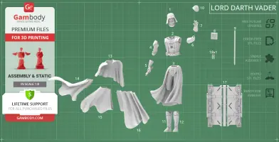
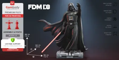
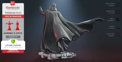
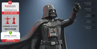
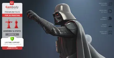
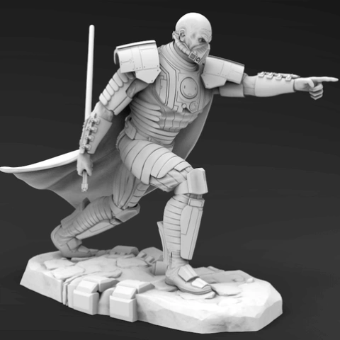
Lord Darth Vader 3D Printing Figurine:
FFF/FDM version:
- Contains 18 parts;
- A printed model is 280 mm tall, 285 mm wide, 262 mm deep;
- The assembly kit includes lock 18_ge_lock_10H(x1) to attach the figurine's body to legs without glue;
- All parts are divided in such a way that you will print them with the smallest number of support structures.
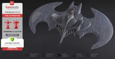
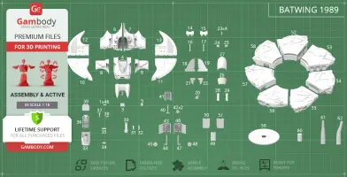
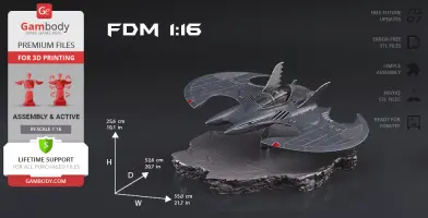
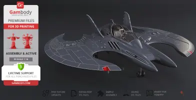
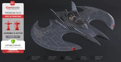
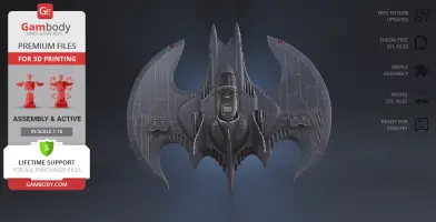
Batwing 1989 3D Printing Model:
FFF/FDM version:
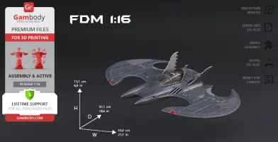
- Contains 62 parts;
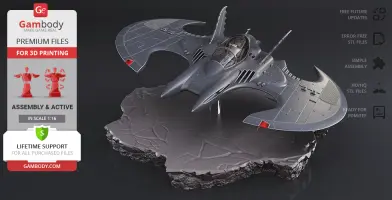
- A printed model is 151 mm tall, 550 mm wide, 471 mm deep;
- A printed model on the stand is 256 mm tall, 550 mm wide, 526 mm deep;
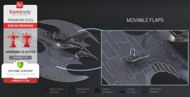
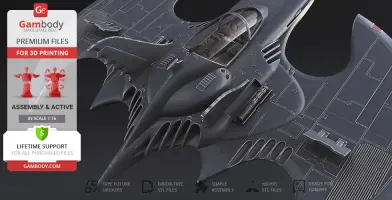
- Movable wing flaps;
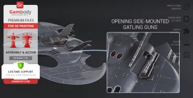
- Opening side-mounted gatling guns;
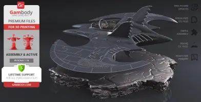
- Opening cockpit canopy;
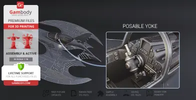
- Posable yoke;
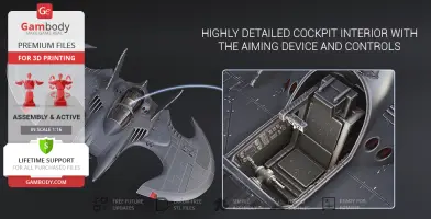
- Highly detailed cockpit interior with the aiming device and controls;
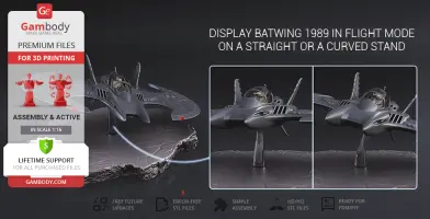
- Display Batwing 1989 in flight mode on a straight or a curved stand;
- Active landing gear;
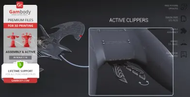
- Opening hull panel reveals the clippers;
- Active clippers;
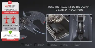
- Press the pedal inside the cockpit to retract the clippers;
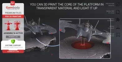
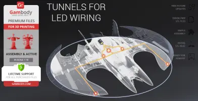
- You can 3D print the core of the platform in transparent material and light it up;
- The cockpit canopy glass is provided as separate assembly parts to be printed using transparent material;
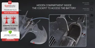
- Tunnels for LED wiring are provided to light up the cockpit, wing lights, and bottom searchlights; the battery can be stored in the hidden compartment inside the cockpit;
- All parts are divided in such a way that you will print them with the smallest number of support structures.
To purchase the bundle comprising Anycubic Kobra Go FDM 3D Printer, Darth Vader 3D Printing Figurine and Batwing 1989 3D Printing Model click the green Buy button in the top-right corner of the model’s page.
Go to the page of Darth Vader 3D Printing Figurine andBatwing 1989 3D Printing Figurine to find more details and additional illustrative material!
These are basic settings that were tested in Cura 4.8.0 slicer.
comics, assembly, star-wars, villain, cinema, villains, dc, action, superhero, dc-comics, vehicle, batman, jedi, joker, film, anycubic, anycubic-gambody-bundles, gambody-anycubic-collaboration, new-star-wars, star-wars-episode-8, star-wars-8, comic-book, star-wars-movies, darth-vader, star-wars-characters, star-wars-games, new-star-wars-movie, anycubic-fdm-3d-printer, tim-burton, gotham, bruce-wayne, gotham-city, sith, anycubic-kobra-go, kobra-go, kobra-go-fdm-3d-printer, diy-3d-printer, master-jedi, star-wars-darth-vader, anakin-skywalker-star-wars-episode-vii, master-darth-vader, darth-vader-jedi, lord-of-siths-stl, batman-1989, batman-returns, batdisc, keaton-mobile, batwing, 3d-printer
You are about to report Anycubic Kobra Go 3D Printer + Darth Vader + Batwing for violating our Terms and Conditions. Please take a few moments to fill in the following information.
We're glad you're here! Before you continue, let's set a few preferences to improve your experience on our marketplace. By clicking "Accept", you agree to our use of cookies to make your visit more enjoyable and personalized. This helps us offer you tailored product recommendations and relevant marketing content. Enjoy your time with Gambody, and thank you for choosing us!
When you visit any website, it may collect and store information through cookies. These small data files help understand your preferences and improve your overall experience. While they usually don't identify you directly, they make your web experience more personalized. We value your privacy and are committed to being transparent about the types of cookies we use and how they enhance your experience. Explore the categories below to learn more and make choices about how your data is used, tailoring your web experience to your comfort level. Please note that rejecting some types of cookies may affect your experience on the marketplace and the services we can offer. For more information, please access our Privacy Policy.
These cookies are crucial for the proper functioning of our website. They support vital features such as privacy settings, logging in, filling out forms (including those for uploading items to the marketplace), and enabling participation in our affiliate program, which allows you to invite friends and earn rewards. Without these cookies, some parts of the site may not work as intended.
These cookies are used by our advertising partners to build a profile of your interests and show you relevant ads on other websites. They do not store personal information directly but are based on uniquely identifying your browser and internet device. If you do not allow these cookies, you will still see ads, but they will be less tailored to you.


Comments
comments powered by Disqus