

This should take overall.

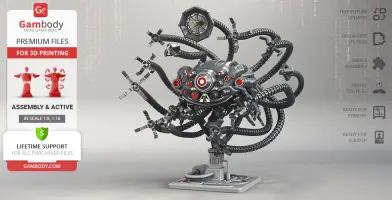
This 3D Model consists of files in StereoLithography (.Stl) format that is optimized for 3D printing.
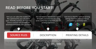
Before printing the files, we strongly recommend reading the PRINTING DETAILS section.
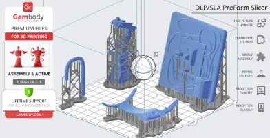
Sentinel 3D Printing Model comes in 2 versions for FFF/FDM and DLP/SLA/SLS 3D printers. STL files of all versions are available for download after purchase.
Detailed information about this 3D printing model is available in the DESCRIPTION section.

|
|||||
|---|---|---|---|---|---|
| File Name | File Size | Time / Filament | Object Size (x/y/z mm) |
||
|
1_ClawBase_x13_fdm (repai red).stl |
0.44 MiB | 31 min <1 m | 23 x 23 x 14 | Download | |
|
2_FingerB_x52_fdm (repair ed).stl |
0.19 MiB | 6 min <1 m | 15 x 19 x 6 | Download | |
|
3_FingerA_x52_fdm (repair ed).stl |
0.16 MiB | 7 min <1 m | 20 x 8 x 6 | Download | |
|
4_Joint_x13_fdm (repaired ).stl |
0.11 MiB | 7 min <1 m | 8 x 8 x 11 | Download | |
|
5_ClawAntenna_fdm (repair ed).stl |
3.58 MiB | 7 h 4 m | 71 x 71 x 55 | Download | |
|
6_JointAntenna_fdm (repai red).stl |
0.11 MiB | 11 min <1 m | 8 x 8 x 17 | Download | |
|
7_Tail_x602_fdm (repaired ).stl |
1.35 MiB | 11 min <1 m | 13 x 13 x 13 | Download | |
|
8_Eye_1_fdm (repaired).st l |
0.26 MiB | 9 min <1 m | 16 x 16 x 5 | Download | |
|
9_Eye_2_fdm (repaired).st l |
0.18 MiB | 3 min <1 m | 6 x 6 x 4 | Download | |
|
10_Eye_3_fdm (repaired).s tl |
0.17 MiB | 1 min <1 m | 3 x 3 x 3 | Download | |
|
11_Eye_4_fdm (repaired).s tl |
0.16 MiB | 4 min <1 m | 7 x 7 x 4 | Download | |
|
12_Eye_5_fdm (repaired).s tl |
0.18 MiB | 2 min <1 m | 5 x 5 x 3 | Download | |
|
13_Eye_6_fdm (repaired).s tl |
0.18 MiB | 2 min <1 m | 5 x 5 x 4 | Download | |
|
14_Eye_7_fdm (repaired).s tl |
0.16 MiB | 3 min <1 m | 7 x 7 x 4 | Download | |
|
15_Eye_8_fdm (repaired).s tl |
0.18 MiB | 3 min <1 m | 6 x 6 x 4 | Download | |
|
16_Eye_9_fdm (repaired).s tl |
0.13 MiB | 4 min <1 m | 8 x 8 x 4 | Download | |
|
17_Eye_10_fdm (repaired). stl |
0.12 MiB | 3 min <1 m | 8 x 8 x 3 | Download | |
|
18_Eye_11_fdm (repaired). stl |
0.12 MiB | 4 min <1 m | 7 x 7 x 5 | Download | |
|
19_Eye_12_fdm (repaired). stl |
0.17 MiB | 1 min <1 m | 4 x 4 x 3 | Download | |
|
20_Eye_13_fdm (repaired). stl |
0.13 MiB | 5 min <1 m | 10 x 10 x 4 | Download | |
|
21_Eye_14_fdm (repaired). stl |
0.12 MiB | 7 min <1 m | 12 x 12 x 5 | Download | |
|
22_Eye_15_fdm (repaired). stl |
0.13 MiB | 4 min <1 m | 8 x 8 x 4 | Download | |
|
23_Eye_16_fdm (repaired). stl |
0.12 MiB | 3 min <1 m | 8 x 8 x 3 | Download | |
|
24_Eye_17_fdm (repaired). stl |
0.12 MiB | 4 min <1 m | 7 x 7 x 5 | Download | |
|
25_Eye_18_fdm (repaired). stl |
0.17 MiB | 1 min <1 m | 4 x 4 x 3 | Download | |
|
26_Eye_19_fdm (repaired). stl |
0.13 MiB | 5 min <1 m | 10 x 10 x 4 | Download | |
|
27_Eye_20_fdm (repaired). stl |
0.12 MiB | 7 min <1 m | 12 x 12 x 5 | Download | |
|
28_Eye_21_fdm (repaired). stl |
0.17 MiB | 1 min <1 m | 3 x 3 x 4 | Download | |
|
29_Eye_22_fdm (repaired). stl |
0.16 MiB | 4 min <1 m | 7 x 7 x 4 | Download | |
|
30_Eye_23_fdm (repaired). stl |
0.06 MiB | 1 min <1 m | 3 x 3 x 4 | Download | |
|
31_Eye_24_fdm (repaired). stl |
0.17 MiB | 2 min <1 m | 5 x 5 x 5 | Download | |
|
32_Eye_25_fdm (repaired). stl |
0.16 MiB | 4 min <1 m | 7 x 7 x 4 | Download | |
|
33_Eye_26_fdm (repaired). stl |
0.06 MiB | 1 min <1 m | 3 x 3 x 4 | Download | |
|
34_Eye_27_fdm (repaired). stl |
0.17 MiB | 2 min <1 m | 5 x 5 x 5 | Download | |
|
35_Eye_28_fdm (repaired). stl |
0.17 MiB | 1 min <1 m | 3 x 3 x 4 | Download | |
|
36_Body_L_fdm (repaired). stl |
52.02 MiB | 55 h 1 min 35 m | 158 x 97 x 87 | Download | |
|
37_Body_R_fdm (repaired). stl |
49.09 MiB | 55 h 9 min 35 m | 158 x 97 x 88 | Download | |
|
38_MainEye_fdm (repaired) .stl |
1.20 MiB | 4 h 34 min 3 m | 49 x 48 x 43 | Download | |
|
39_Mouth_fdm (repaired).s tl |
0.57 MiB | 37 min <1 m | 27 x 18 x 19 | Download | |
|
40_Ge_lock_x9 (repaired). stl |
0.03 MiB | 4 min <1 m | 18 x 10 x 2 | Download | |
|
41_Fastening_X14_fdm (rep aired).stl |
0.45 MiB | 20 min <1 m | 16 x 16 x 14 | Download | |
|
42_Paw_x14_fdm (repaired) .stl |
1.47 MiB | 29 min <1 m | 16 x 10 x 32 | Download | |
|
43_Antenna_B_fdm (repaire d).stl |
0.34 MiB | 16 min <1 m | 5 x 14 x 30 | Download | |
|
44_Trube_R_fdm (repaired) .stl |
0.10 MiB | 17 min <1 m | 10 x 8 x 32 | Download | |
|
45_Antenna_L_fdm (repaire d).stl |
0.34 MiB | 8 min <1 m | 3 x 9 x 20 | Download | |
|
46_Trube_L_fdm (repaired) .stl |
0.10 MiB | 16 min <1 m | 9 x 8 x 32 | Download | |
|
47_Hand_claw_x10_fdm(repa ired).stl |
0.15 MiB | 5 min <1 m | 11 x 10 x 5 | Download | |
|
48_Hand_Joint_x10_fdm (re paired).stl |
0.28 MiB | 9 min <1 m | 7 x 7 x 16 | Download | |
|
49_Hand_A_x10_fdm (repair ed).stl |
1.30 MiB | 32 min <1 m | 12 x 14 x 35 | Download | |
|
50_Hand_B_x10_fdm (repair ed).stl |
4.64 MiB | 49 min <1 m | 17 x 18 x 38 | Download | |
|
51_Hand_C_x10_fdm (repair ed).stl |
4.77 MiB | 49 min <1 m | 15 x 15 x 33 | Download | |
|
52_Base1_fdm (repaired).s tl |
3.95 MiB | 9 h 33 min 7 m | 107 x 130 x 43 | Download | |
|
53_Base2_fdm (repaired).s tl |
7.38 MiB | 15 h 57 min 11 m | 38 x 60 x 138 | Download | |
|
54_Platform_fdm (repaired ).stl |
15.23 MiB | 24 h 10 min 13 m | 152 x 161 x 33 | Download | |
|
55_Lock_x4_fdm (repaired) .stl |
0.09 MiB | 7 min <1 m | 18 x 14 x 5 | Download | |
|
56_Trube3_fdm (repaired). stl |
0.54 MiB | 13 min <1 m | 24 x 4 x 14 | Download | |
|
57_Trube4_fdm (repaired). stl |
0.72 MiB | 23 min <1 m | 11 x 20 x 24 | Download | |
|
58_Trube5_fdm (repaired). stl |
0.19 MiB | 25 min <1 m | 7 x 28 x 24 | Download | |
|
59_BigTrube1_fdm (repaire d).stl |
10.58 MiB | 1 h 27 min 1 m | 61 x 14 x 41 | Download | |
|
60_BigTrube2_fdm (repaire d).stl |
0.88 MiB | 50 min <1 m | 9 x 9 x 60 | Download | |
|
61_KlopStand_x4 (repaired ).stl |
0.03 MiB | 4 min <1 m | 10 x 18 x 2 | Download | |
|
62_Trube1_fdm (repaired). stl |
0.14 MiB | 35 min <1 m | 18 x 3 x 39 | Download | |
|
63_Trube2_fdm (repaired). stl |
0.13 MiB | 38 min <1 m | 3 x 19 x 40 | Download | |
|
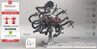
Keychain (repaired).stl |
0.35 MiB | 23 min <1 m | 30 x 30 x 2 | Download | |
|
Tag (repaired).stl |
1.70 MiB | 1 h 16 min 1 m | 150 x 18 x 5 | Download | |
|
7_Tail_v2_x602_5%_smaller _ball (repaired).stl |
1.36 MiB | 11 min <1 m | 13 x 13 x 12 | Download | |
|
7_Tail_v3_x602_7%_smaller _ball (repaired).stl |
1.36 MiB | 11 min <1 m | 13 x 13 x 12 | Download | |
|
36_v2_Body_L_not_hollow_f dm (repaired).stl |
45.91 MiB | 47 h 23 min 26 m | 158 x 97 x 87 | Download | |
|
37_v2_Body_R_not_hollow_f dm (repaired).stl |
43.08 MiB | 47 h 14 min 26 m | 158 x 97 x 88 | Download | |
| ... | |||||
This should take overall.
ABOUT THIS 3D MODEL
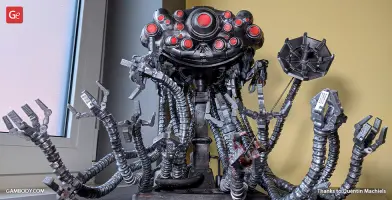
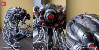
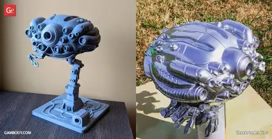
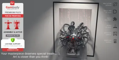
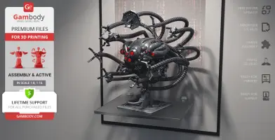
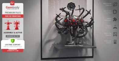
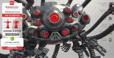
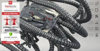
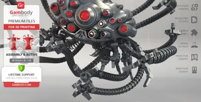
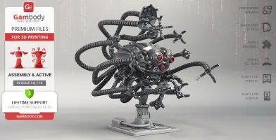
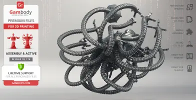
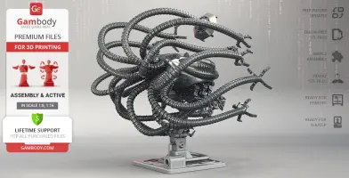
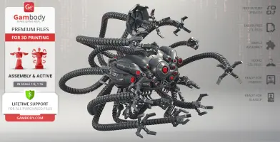
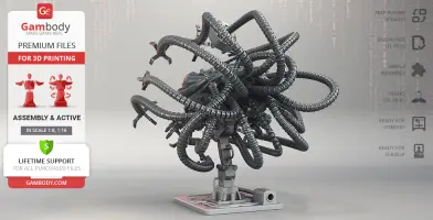
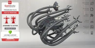
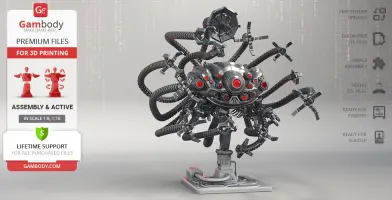
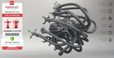
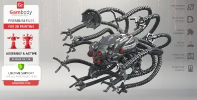
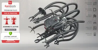
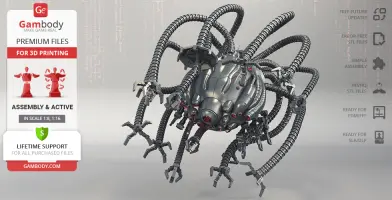
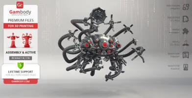
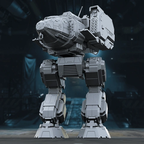
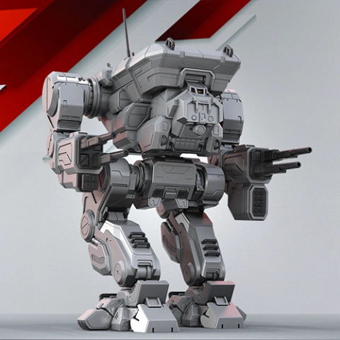
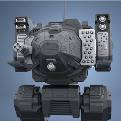
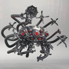
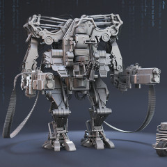
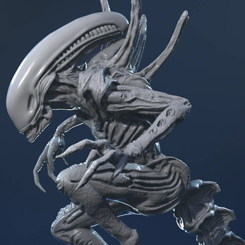
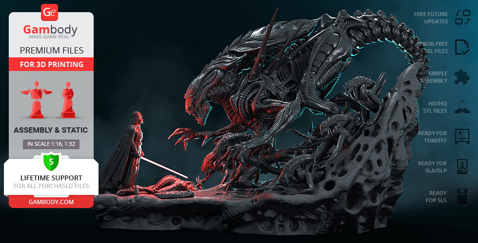
Sentinels are terrifying multi-tentacled killing machines that maintain the physical structures of the Matrix within The Wachowskis’ franchise of the same name. A strong resemblance of the machines to cephalopods resulted in the Human Resistance calling them “squiddies”. Similar to squids Sentinels move in large swarms, usually patrolling the now-dead human cities in search of wandering humans. The deadly machines move through the air with ease and are considered to be using some kind of sophisticated hover pad technology, far more improved than the one used in transportation utilized by Human Resistance. The frightening swarm of antagonists that serve to eradicate humankind is undoubtedly an impressive part of the iconic sci-fi universe. Thanks to our talented contributing 3D artist who dedicated circa 180 hours working on the project the awesome Sentinel model is now available for 3D printing. The author of the model did a spectacular job depicting the dreadful robotic appearance of the Sentinel, with its large pod-shaped head and many sharp-clawed tentacles extending from the back. In addition to numerous round eyes on the robot’s head, the 3D artist made sure to equip one of the model’s many tentacles with a satellite dish that is known to serve as an audio and visual sensor. Paying the utmost attention to fine details, the 3D artist carefully included two sets of crab-like appendages on both sides of the machine’s belly, as well as small antennas and sensors on top of its head. The Battle of Zion starring hundreds of piloted APUs under Captain Mifune’s command is a truly remarkable robotic battle scene. Now, thanks to the possibilities that 3D printing technology offers, you can recreate the actual scenario at home! The STL files of Sentinel, the killing machine designed for search and destroy, are ready for download!
ADAPTATION FOR 3D PRINTING
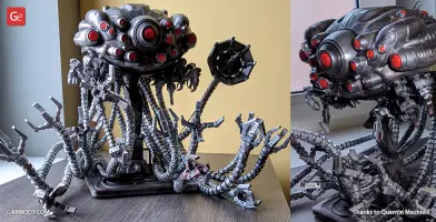
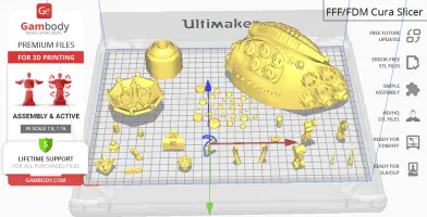
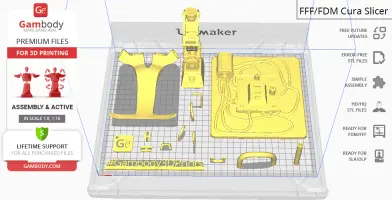
Sentinel model for 3D printing is a highly articulated action assembly model and its moderation and adaptation for different types of 3D printers took Gambody team 65 hours in total. In order to ensure the multidirectional movement of the Squiddy’s appendages, the model was divided into many assembly parts and special mechanisms were introduced into all model’s joints to give you an opportunity to display the machine in a variety of positions or scenarios. Thus, the model’s crab-like appendages in front are movable in all four junctions and every single joint comprising each model’s long tentacle rotates with the help of a ball-and-claw connection. It is recommended to assemble each tentacle using 43 tail parts but you can make any tentacle shorter and longer by adding or removing these tail pieces. Every single Sentinel’s claw in FFF/FDM version is fully articulated as well. The assembly of these movable claws requires additional “pins”. These pins do not come in STL files but can be made out of short pieces of regular 1.75 PLA. All Sentinel's eyes are provided separately in the model’s FFF/FDM 1.0 version for you to print them in the transparent filament. The machine's body is hollow in both model’s versions for you to introduce LED wiring and light up the eyes. All assembly parts are provided in STL files in recommended positions that were worked out to ensure the smoothness of the details’ surfaces after printing and so that the 3D printing beginners won't face difficulties when placing the parts on a build plate. We highly recommend that you watch "Assembly video" in the photo preview section before assembling the Sentinel. When downloading any model's file you will also receive "Assembly Manual" for FFF/FDM 1.0 and DLP/SLA/SLS 1.0 versions in PDF format.
The model is saved in STL files, a format supported by most 3D printers. All STL files for 3D printing have been checked in Netfabb and no errors were shown.
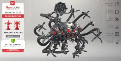
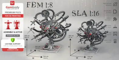
The model's scale was calculated from the actual size of the Sentinel's head that is 1400mm x 1120mm x 770mm. The 3D printing model's chosen scale is 1/8 for the FFF/FDM version and 1/16 for the DLP/SLA/SLS versions.
VERSION SPECIFICATIONS
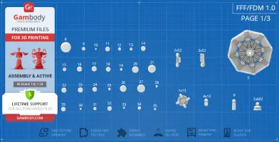
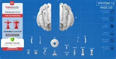
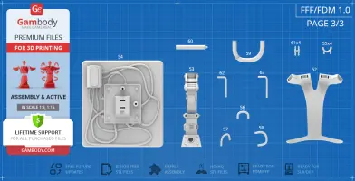
FFF/FDM 1.0 version features:
- Contains 63 parts;
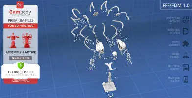
- A printed model is 359 mm tall, 339 mm wide, 360 mm deep;
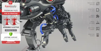
- Made with several sets of special joints to ensure the model's articulation - all Sentinel’s claws, crab-like hands, tentacles, and the satellite dish are fully articulated;
- The assembly of Sentinel's articulated claws requires additional “pins”. These pins do not come in STL files but can be made out of short pieces of regular 1.75 PLA;
- There are many assembly parts that need to be printed multiple times - the number of required copies (x5, x20 etc.) is indicated in the title of the file in “Source files” tab, e.g. file "1_ClawBase_x13" needs to be printed 13 times;
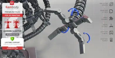
- Every single joint comprising each tentacle rotates with the help of a ball-and-claw connection;
- In order to assemble one tentacle, it is recommended to print the part “7_Tail_x602” 43 times. But you can make any tentacle shorter and longer by adding or removing parts“7_Tail_x602” ;
- All Sentinel's eyes are provided separately for you to print them in transparent filament;
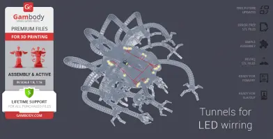
- The machine's body is hollow for you to introduce LED wiring;
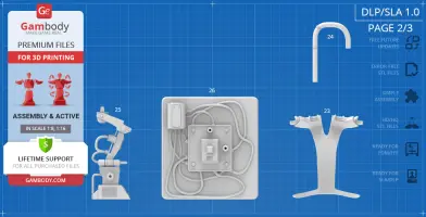
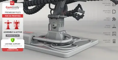
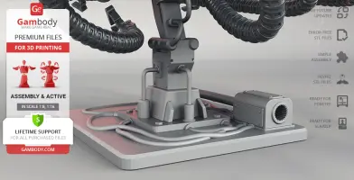
- The model comes with a special stand for you to conveniently display the round Sentinel with its many long tentacles;
- Assembly kit includes locks to connect the model's body and display stand securely without glue. Lock 40_Ge_lock_x9 needs to be printed 9 times; lock 55_Lock_x4 needs to be printed 4 times;
- It is highly recommended that you watch "Assembly video" in the photo preview section and read "Assembly Manual" in PDF before assembling the Sentinel;
- There are alternative variants of the tentacle part 7_Tail_v2_x602_5%_smaller_ball and 7_Tail_v3_x602_7%_smaller_ball that have slightly shortened "stems" and the ball connector decreased in size by 5% and 7% respectively;
- All parts are divided in such a way that you will print them with the smallest number of support structures.
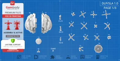
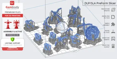
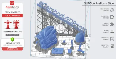
DLP/SLA/SLS 1.0 version features:
- Contains 26 parts;
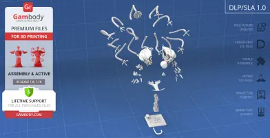
- A printed model is 180 mm tall, 170 mm wide, 180 mm deep;
- Made with several sets of special joints to ensure the model's articulation - all Sentinel’s crab-like hands, the satellite dish, and tentacles are fully articulated;
- There are many assembly parts that need to be printed multiple times - the number of required copies (x5, x20 etc.) is indicated in the title of the file in “Source files” tab, e.g. file "19_Hand1_A_x10" needs to be printed 10 times;
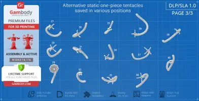
- The model's claws are static but they are saved in different positions that you can attach to the tentacles as you prefer;
- Every single joint comprising each tentacle rotates with the help of a ball-and-claw connection;
- In order to assemble one tentacle, it is recommended to print the part “22_Tail_x602” 43 times. But you can make any tentacle shorter and longer by adding or removing parts“22_Tail_x602” ;
- The machine's body is hollow for you to introduce LED wiring;
- The model comes with a special stand for you to conveniently display the round Sentinel with its many long tentacles;
- It is highly recommended that you watch "Assembly video" in the photo preview section and read "Assembly Manual" in PDF before assembling the Sentinel;
- All parts are divided in such a way that you will print them with the smallest number of support structures.
WHAT WILL YOU GET AFTER PURCHASE?
- STL files of Sentinel for 3D printing which consist of 89 parts;
- 2 versions of files for this model for FFF/FDM and DLP/SLA/SLS;
- High-poly detailed model of Sentinel;
- Assembly Manual for FFF/FDM 1.0 and DLP/SLA/SLS 1.0 versions in PDF format;
- Detailed settings that we provide as a recommendation for Cura , Simplify3D and Slic3r for the best print;
- Full technical support from the Gambody Support Team.
You can get the model of Sentinel for 3D Printing immediately after the purchase! Just click the green Buy button in the top-right corner of the model’s page. You can pay with PayPal or your credit card.
Watch the tutorial on how to assemble the Sentinel 3D Printing Model at Gambody YouTube channel.
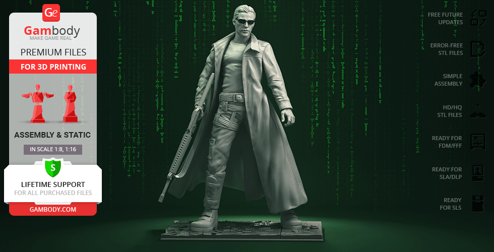
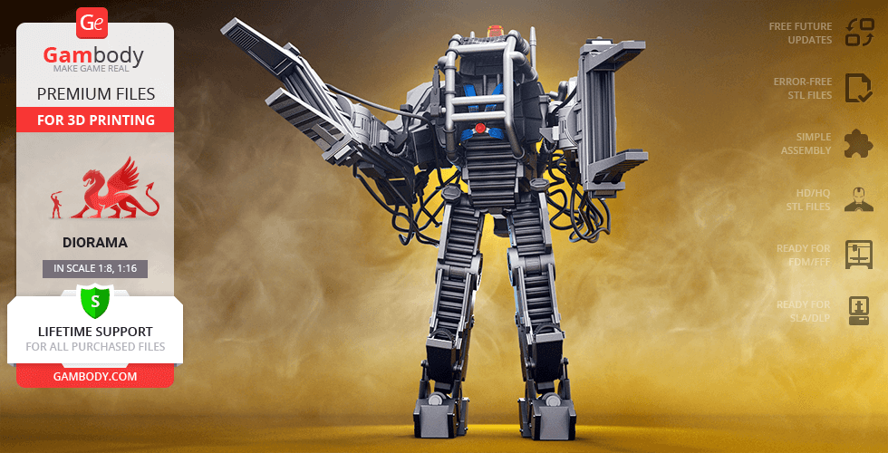
Also, you may like Neo 3D Printing Figurine, as well as Matrix APU 3D Printing Model.
_______
FAQ:
Where can I print a model if I have no printer?
How to get started with 3D printing?
How to set up my 3D printer?
How to choose right 3D model print bed positioning?
How to paint printed figurine?
Below you can find printing recommendations for Cura, Simplify3D and Slic3r software.
These are basic settings that were tested in Cura 4.8.0 slicer.
The test models were printed on Ultimaker 2, Creality Ender 3, Creality CR-10S Pro V2, Anycubic I3 Mega, Anycubic I3 MegaS 3D printers with PLA and PETG filaments.
Disclaimer: The following printing settings are a recommendation, not an obligation. The parameters can vary depending on the peculiarities of your 3D printer, the material you use and especially the particular assembly part at hand. Each part that any model comprises often needs preliminary review and you are free to tweak the settings the way you find suitable.
Note:
- You can scale up the model (downscaling is not recommended!);
- All connectors should be printed at 100% Infill;
- For all parts of locks (“ge_lock” in “Source files”) you need to change "Brim" type to "Skirt" in Build Plate Adhesion section.
Quality
Layer Height: 0.12 mm (you can also set Layer Height at 0.16 or 0.2mm for 0.4mm nozzles)
Initial Layer Height: 0.2 mm (carefully level the print bed and keep your Initial Layer Height the same as the main Layer Height)
Line Width: 0.4 mm
Wall Line Width: 0.4 mm
Outer Wall Line Width: 0.4 mm
Inner Wall(s) Line Width: 0.4 mm
Top/Bottom Line Width: 0.4 mm
Infill Line Width: 0.4 mm
Skirt/Brim Line Width: 0.4 mm
Support Line Width: 0.4 mm
Initial Layer Line Width: 100%
Shell
Wall Thickness: 0.8 mm
Wall Line Count: 2
Outer Wall Wipe Distance: 0.3 mm
Top Surface Skin Layers: 0
Top/Bottom Thickness: 0.6 mm
Top Thickness: 0.6 mm
Top Layers: 5
Bottom Thickness: 0.6 mm
Bottom Layers: 5
Initial Bottom Layers: 5
Top/Bottom Pattern: Lines
Bottom Pattern Initial Layer: Lines
Top/Bottom Line Directions: [ ]
Outer Wall Inset: 0 mm
Optimize Wall Printing Order: Check
Compensate Wall Overlaps: Check
Compensate Inner Wall Overlaps: Check
Minimum Wall Flow: 0%
Fill Gaps Between Walls: Everywhere
Filter Out Tiny Gaps: Check
Horizontal Expansion: 0 mm
Initial Layer Horizontal Expansion: 0 mm
Hole horizontal expansion: 0
Z Seam Alignment: User Specified
Z Seam Position: Back
Z Seam X: Average length of your printer’s plate (e.g.”150” if your plate is 300mm on the X-axis)
Z Seam Y: A value higher than the length of your plate on the Y-axis (e.g. 700)
Seam Corner Preference: Hide Seam
Extra Skin Wall Count: 1
Skin Overlap Percentage: 10%
Skin Overlap 0.04 mm
Infill
Infill Density: 20% (for all smaller parts and for all parts of connectors use 100% Infill)
Infill Pattern: Triangles
Connect Infill Lines: Check
Infill Line Directions: [ ]
Infill X Offset: 0 mm
Infill Y Offset: 0 mm
Infill Line Multiplier: 1
Extra Infill Wall Count: 0
Infill Overlap Percentage: 10-20%
Infill Overlap: 0.04 mm
Skin Overlap Percentage: 5%
Skin Overlap: 0.02 mm
Infill Wipe Distance: 0 mm
Infill Layer Thickness: 0.24 mm
Gradual Infill Steps: 0
Infill Before Walls: Check
Minimum Infill Area: 0 mm2
Skin Removal Width: 0.8 mm
Top Skin Removal Width: 0.8 mm
Bottom Skin Removal Width: 0.8 mm
Skin Expand Distance: 0.8
Top Skin Expand Distance: 0.8
Bottom Skin Expand Distance: 0.8
Maximum Skin Angle for Expansion: 90˚
Minimum Skin Width for Expansion: 0.0
Skin Edge Support Thickness: 0
Skin Edge Support Layers: 0
Material
Initial Layer Flow: 100%
Printing Temperature: See your filament settings
Initial Printing Temperature: Your filament settings
Final Printing Temperature: Your filament settings
Build Plate Temperature: Your filament settings
Build Plate Temperature Initial Layer: Your filament settings + 5°
Flow: 100% (Important! If you face difficulty printing the model, you may need to adjust the Flow parameter. You may research the topic using the Internet or seek assistance at our Customer Support Team at support@gambody.com)
Speed
You can increase the printing Speed by 20% when you print simple objects. For small/thin parts you need to decrease the Speed by 25% - 50%.
Print Speed: 50 mm/s
Infill Speed: 50 mm/s
Wall Speed: 25 mm/s
Outer Wall Speed:25 mm/s
Inner Wall Speed: 50 mm/s
Top/Bottom Speed: 25mm/s
Support Speed: 25 mm/s
Support Infill Speed: 45 mm/s
Support Interface Speed: 25 mm/s
Support Roof Speed: 25 mm/s
Support Floor Speed: 25 mm/s
Travel Speed: 80 mm/s
Initial Layer Speed: 80 mm/s
Initial Layer Print Speed: 20 mm/s
Initial Layer Travel Speed: 80 mm/s
Skirt/Brim Speed: 20 mm/s
Z Hop Speed: 5 mm/s
Number of Slower Layers: 2
Enable Acceleration Control: Check
When printing simple objects, you need to set all Acceleration parameters at 500 mm/s. For small/thin parts you need to decrease the Acceleration by 50% - 70%.
Travel
Enable Retraction: Check
Retraction Distance: 4-8 mm, 1-3 mm for Direct Extruder (This is the most important retraction parameter. You can find your optimal value of Retraction Distance by printing any test object, e.g. bridges, towers etc.)
Retraction Speed: 25mm/s
Retraction Retract Speed: 25 mm/s
Retraction Prime Speed: 25 mm/s
Retraction Extra Prime Amount: 0 mm3
Retraction Minimum Travel: 1.5 mm
Maximum Retraction Count: 100
Minimum Extrusion Distance Window: 6,5 - 10 mm
Limit Support Retractions: Check
Combing Mode: All
Max Comb Distance With No Retract: 30 mm
Retract Before Outer Wall: Check
Avoid Printed Parts When Travelling: Check
Avoid Supports When Travelling: Check
Travel Avoid Distance: 1 mm
Layer Start X: 0.0 mm
Layer Start Y: 0.0 mm
Z Hop When Retracted: Check
Z Hop Height: 0,3 mm
Cooling
Enable Print Cooling: Check
Fan Speed: 100%
Regular Fan Speed: 100%
Maximum Fan Speed: 100%
Regular/Maximum Fan Speed Threshold: 10 s
Initial Fan Speed: 0%
Regular Fan Speed at Height: 0.36 mm
Regular Fan Speed at Layer: 3
Minimum Layer Time: 10 s
Minimum Speed: 10 mm/s
Support
Generate Support: Check
Support Structure: Normal (you can try using Tree Support Structure if you have difficulty printing any particular assembly part)
Support Placement: Everywhere
Support Overhang Angle: 60° (this parameter can range from 30° to 70° depending on the part at hand)
Support Pattern: Zig Zag
Support Wall Line Count: 1 (stronger support that might be more difficult to remove) 0 (less strong support but is easier to remove)
Support Density: 15%
Support Line Distance: 2.6667 mm
Initial layer support line distance: 2.667 mm
Support Z Distance: 0.12 mm
Support Top Distance: 0.12 mm
Support Bottom Distance: 0.12 mm
Support X/Y Distance: 0.8-1 mm
Support Distance Priority: Z overrides X/Y
Support Stair Step Height: 0.3 mm
Support Stair Step Maximum Width: 5.0 mm
Support Stair Step Minimum Slope Angle: 10°
Support Join Distance: 2.0 mm
Support Horizontal Expansion: 0.2 mm
Support Infill Layer Thickness: 0.2 mm
Gradual Support Infill Steps: 0
Minimum Support Area: 2 mm
Enable Support Interface: Check (generates additional “pillow” on the support structure that leads to a more even surface, but can be difficult to remove in hard-to-reach areas)
Enable Support Roof: Check
Enable Support Floor: Check
Support Interface Thickness: 0.8 mm
Support Roof Thickness: 0.8 mm
Support Floor Thickness: 0.8 mm
Support Interface Resolution 0.2 mm
Support Interface Density: 50-100%
Support Roof Density: 50-100%
Support Roof Line Distance: 0.8 mm
Support Floor Density: 50-100%
Support Floor line Distance: 0.4mm
Support Interface Pattern: Grid
Support Roof Pattern: Grid (this parameter should differ from Bottom Pattern Initial Layer in “Shell” section)
Support Floor Pattern: Grid
Minimum Support Interface Area: 10mm
Minimum Support Roof Area: 10 mm
Minimum Support Floor Area: 10 mm
Support Interface Horizontal Expansion: 0.0 mm
Support Roof Horizontal Expansion: 0.0 mm
Support Floor Horizontal Expansion: 0.0 mm
Fan Speed Override: Check
Supported Skin Fan Speed: 100%
Use Towers: Check
Tower Diameter: 4 mm
Minimum Diameter: 3.0 mm
Tower Roof Angle: 65°
Build Plate Adhesion
Build Plate Adhesion Type: Skirt/Brim (For unsteady parts, and those parts that may come unstuck use “Brim”. For bigger assembly parts that have large adhesion area and for all parts of locks and claws that you want to come out clean use "Skirt")
Skirt/Brim Minimum Length: 250 mm
Brim Width: 8.0 mm
Brim Line Count: 10
Brim Only on Outside: Check
Mesh Fixes
Union Overlapping Volumes: Check
Merged Meshes Overlap: 0.15 mm
Special Modes
Print Sequence: All at Once
Surface Mode: Normal
Experimental
Slicing Tolerance: Middle
Maximum Resolution: 0.01 mm
Flow rate compensation max extrusion offset: 0 mm
Flow rate compensation factor: 100%
This model was tested with PLA material.
To avoid printing problems, we recommend the following settings:
Extruder
Nozzle Diameter: 0.4 mm
Extrusion Multiplier: 0.97
Extrusion Width: Auto
Retraction Distance: 5.00 mm
Extra Restart Distance: 0.00 mm
Retraction Vertical Lift: 0.08 mm
Retraction Speed: 5400.0 mm/min
Wipe Distance: 5.00 mm
Layer
Primary Layer Height: 0.2 mm
Top Solid Layers: 8
Bottom Solid Layers: 5
Outline/Perimeter Shells: 2
Outline Direction: Inside-Out
First Layer Height: 90%
First Layer Width: 100%
First Layer Speed: 20%
Additions
Use Skirt/Brim: Check
Skirt Layers: 1
Skirt Offset from Part: 6.00 mm
Skirt Outlines: 5
Infill
Internal Fill Pattern: Fast Honeycomb
External Fill Patern: Rectilinear
Interior Fill Percentage: 10%
Outline Overlap: 22%
Infill Extrusion Width: 100%
Minimum Infill Length: 5.00 mm
Combine Infill Every: 1 layers
External Infill Angle Offsets: 45/-45 deg
Support
Generate Support Material: Check
Support Infill Percentage: 15%
Extra Inflation Distance: 1.00 mm
Support Base Layers: 0
Combine Support Every: 1 layers
Dense Support Layers: 0
Dense Infill Percentage: 70%
Support Type: Normal
Support Pillar Resolution: 5.00 mm
Max Overhang Angle: 60 deg
Horizontal Offset From Part: 0.50 mm
Upper Vertical Separation Layers: 1
Lower Vertical Separation Layers: 1
Support Infill Angles: 45 deg
Temperature
Extruder 1 Temperature: 210
Heated Bed: 60
Cooling
Increase fan speed for layers below: 45.0 sec
Maximum Cooling fan speed: 50%
Bridging fan speed override: 100%
Speeds
Default Printing Speed: 4800.0 mm/min
Outline Underspeed: 50%
Solid Infill Underspeed: 80%
Support Structure Underspeed: 80%
X/Y Axis Movement Speed: 10800.0 mm/min
Z Axis Movemen Speed: 1002.0 mm/min
Adjust printing speed for layers below: 15.0 sec
Allow speed reduction down to: 20%
Other
Unsupported area threshold: 20.0 sq m
Layer height
Layer height: 0.1 mm
First layer height: 90%
Vertical shells
Perimeters: 2
Horizontal shells
Soid layers:
Top: 8
Bottom: 5
Quality
Detect thin walls: Check
Detect bridging perimeters: Check
Advanced
Seam position: Random
Infill
Fill desity: 20%
Fill pattern: Honeycomb
Top/bottom fill pattern: Rectilinear
Reducing printing time
Combine infill every: 1 layers
Advanced
Solid infill every: 0 layers
Fill angle: 25 deg
Solid infill threshold area: 0mm
Skirt
Loops: 2
Distance from object: 6 mm
Skirt height: 1 layers
Minimum extrusion length: 4 mm
Brim
Brim width: 10 mm
Support material
Generate support material: Check
Overhang threshold: 45 deg
Enforce support for the first: 3 layers
Raft
Raft layers: 0 layers
Options for support material and raft
Contact Z distance: 0.1 mm
Pattern: Rectilinear
Patter spacing: 2 mm
Pattern angle: 0 deg
Interface layers: 2 layers
Interface pattern spacing: 0.2 mm
Speed for print moves
Perimeters: 60 mm/s
Small perimeters: 20 mm/s
External perimeters: 20 mm/s
Infill: 60 mm/s
Solid infill: 60 mm/s
Top solid infill: 30 mm/s
Support material: 50 mm/s
Support material interface: 100%
Bridges: 30 mm/s
Gap fill: 50 mm/s
Speed for non-print moves
Travel: 60 mm/s
Modifiers
First layer speed: 30 mm/s
Acceleration control
Perimeters: 800 mm/s
Infill: 1500 mm/s
Bridge: 1000 mm/s
First layer: 1000 mm/s
Default: 1000 mm/s
Autospeed
Max print speed: 100 mm/s
Max volumetrix speed: 0 mm/s
Extrusion width
Default extrusion width: 0.42 mm
First layer: 0.42 mm
Perimeters: 0.42 mm
External perimeters: 0.42 mm
Infill: 0.42 mm
Solid infill: 0.42 mm
Top solid infill: 0.42 mm
Support material: 0.42 mm
Overlap
Infill/Perimeters overlap: 20%
Flow
Bridge flow ratio: 0.95
Other
XY Size Compensation: 0 mm
Threds: 8
Resolution: 0 mm
diorama, robot, horror, sci-fi, drone, machine-war, matrix, the-matrix, sentinel, sentinels, apu, zion, battle-of-zion, the-matrix-reloaded, the-matrix-revolutions, machine
You are about to report Sentinel 3D Printing Model | Assembly + Action for violating our Terms and Conditions. Please take a few moments to fill in the following information.


Comments
comments powered by Disqus