


Files
3D model format
Stereolithography (.stl)
Total files
Slicer settings
Mesh error check
Netfabb
Support
Lifetime support from Gambody team
Update requests
Available to verified buyers
Model complexity
Standard: balanced printing difficulty and moderate part count with assembly steps.
Model versions
FFF/FDM
Assembly method
Connectors
Features
- Updated version featuring a more canonical design and historical accuracy;
- Optimized for multi-color printing and easy slicer-based painting with recessed grooves on engine fairings;
- Includes separated stabilizers (with/without lettering) and removable black stripes for the lower hull;
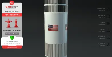
- Refined USA/United States markings, added flag texture, and updated black roll patterns on the S-IC and S-II stages for true-to-life precision;
- Relocated external conduits;
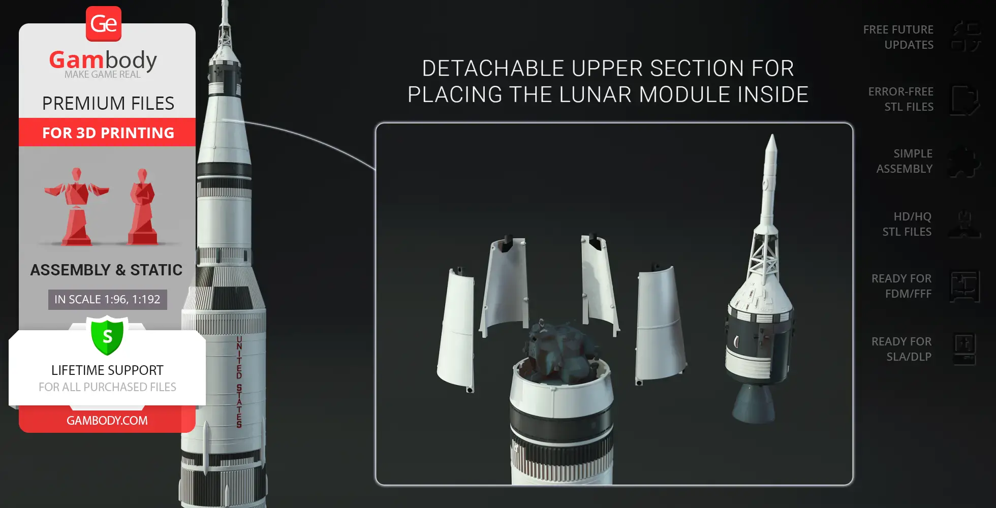
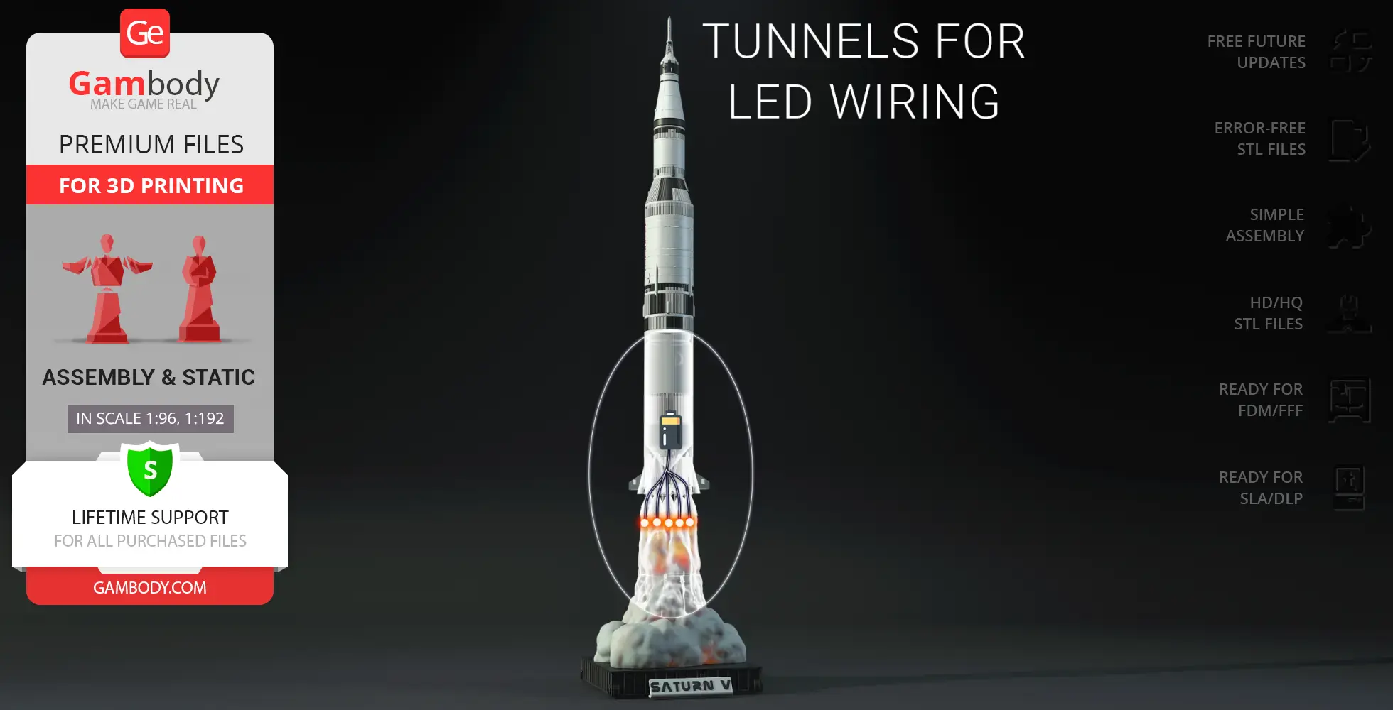
- Includes all Version 1.0 features: standard and LED-ready first-stage options, detachable upper section for the Lunar Module, and three display stand variants (static, LED-flame, and horizontal diorama);
- The assembly parts are connected using specially designed integrated connectors that fit securely into the corresponding slots.
DLP/SLA
Eco parts
Assembly method
Connectors, Glue
Features
- Updated version featuring a more canonical design and historical accuracy;
- Optimized for ease of painting with recessed boundaries on engine fairings;
- Includes separated stabilizers and updated black roll patterns across the 1st and 2nd stages;
- Enhanced with flag texture and corrected USA/United States lettering positions;
- Includes all 1.0 Version features: standard and LED-ready stage options, interior for the Lunar Module, and three display stand variants;
- The assembly parts are connected using specially designed integrated connectors that fit securely into the corresponding slots. Optionally, for added strength and rigidity, the static connections can be glued together.
FFF/FDM
Assembly method
Connectors
Features
Two body versions: with and without lettering; Four first-stage options: with or without lettering, available in both standard and LED-ready versions; Three display stand options: static, smoke-and-flame LED-ready, and horizontal diorama base; Detachable upper section for placing the Lunar Module inside; Optional transport cover for second stage; The assembly parts are connected using specially designed integrated connectors that fit securely into the corresponding slots.
DLP/SLA
Eco parts
Assembly method
Connectors, Glue
Features
Two body versions: with and without lettering; Four first-stage options: with or without lettering, available in both standard and LED-ready versions; Three display stand options: static, smoke-and-flame LED-ready, and horizontal diorama base; Detachable upper section for placing the Lunar Module inside; Optional transport cover for second stage; The assembly parts are connected using specially designed integrated connectors that fit securely into the corresponding slots. Optionally, for added strength and rigidity, the static connections can be glued together.
Additional details
Part of diorama
Yes
Other model in diorama
Special pack included
No
You will get instant access to the STL files of Apollo 11 Saturn V 3D Printer Files | Assembly after completing your purchase. Simply add the model to your cart and check out using PayPal, credit or debit card, Apple Pay, Google Pay, Alipay, or other available payment methods.
Watch the assembly video for Apollo 11 Saturn V 3D Printer Files | Assembly, and explore more tutorials, behind-the-scenes content, 3D printing timelapses, and painting guides on the official Gambody YouTube channel.
This 3D model comes with StereoLithography (.STL) files optimized for 3D printing. You'll get digital files, not a physical product
Before printing, take a look at Printing Details for recommended settings and tips to achieve better results.
Apollo 11 Saturn V 3D Printer Files | Assembly includes 2 version(s) for the supported 3D printer type(s): FFF/FDM, DLP/SLA. Files are available for download after purchase.
See the Description and Specifications sections for more details about this model.
3D model history
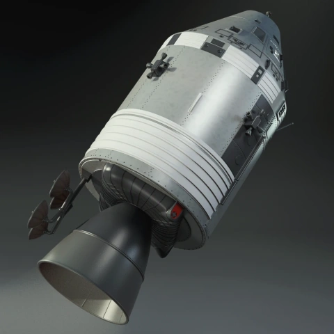
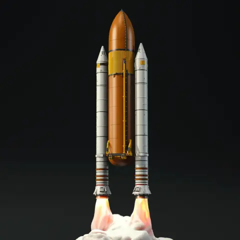
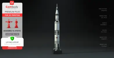
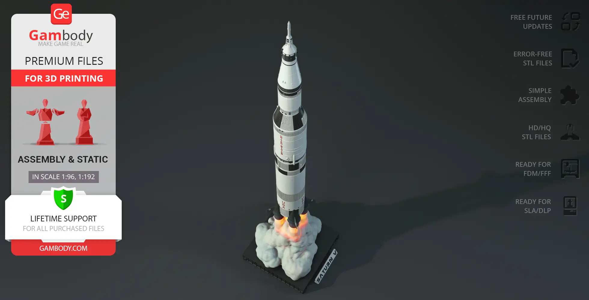
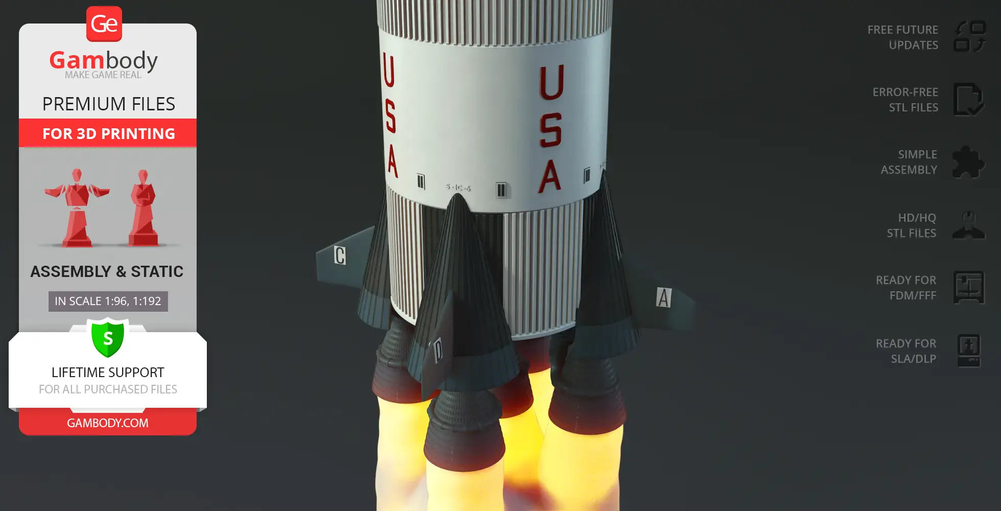
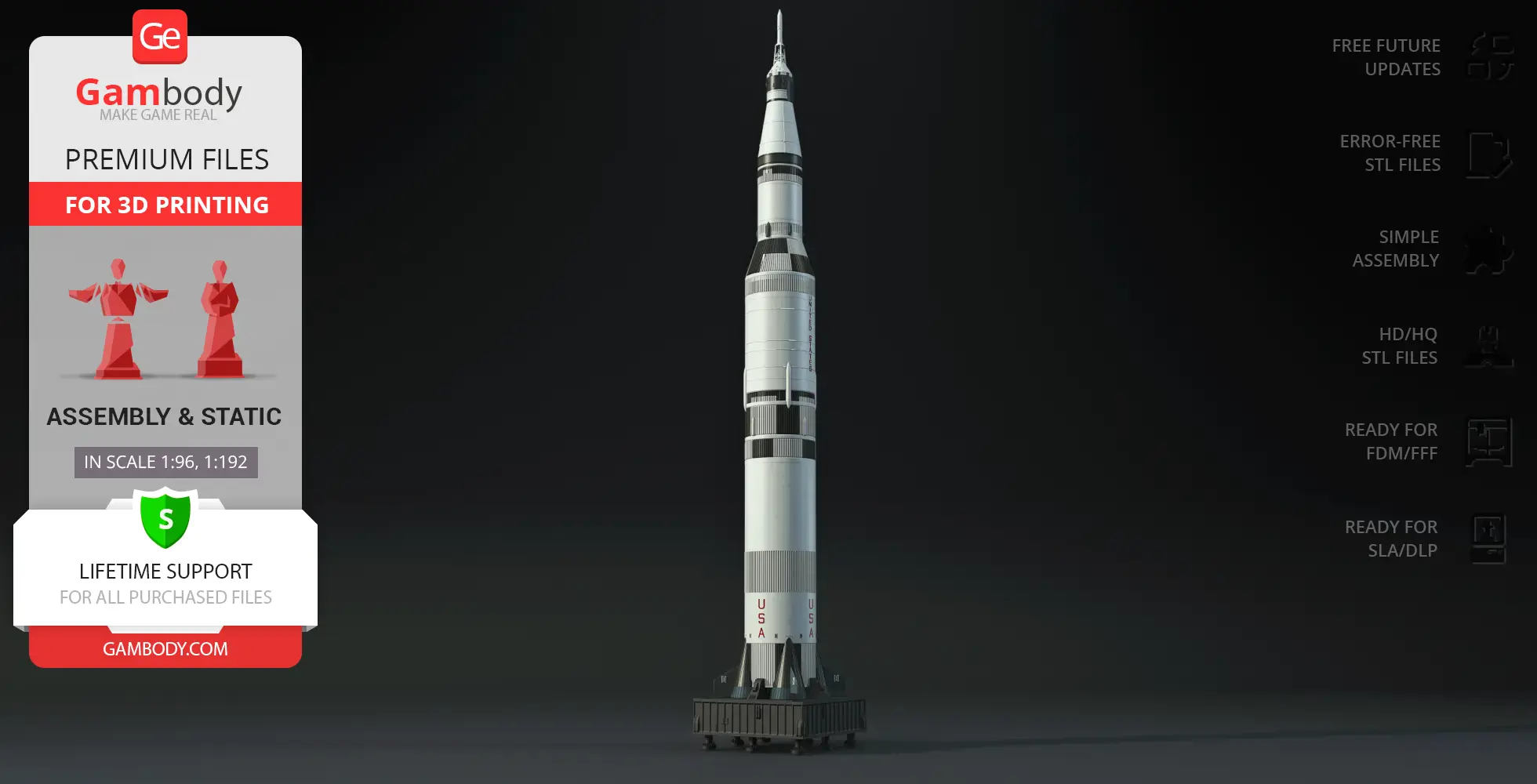
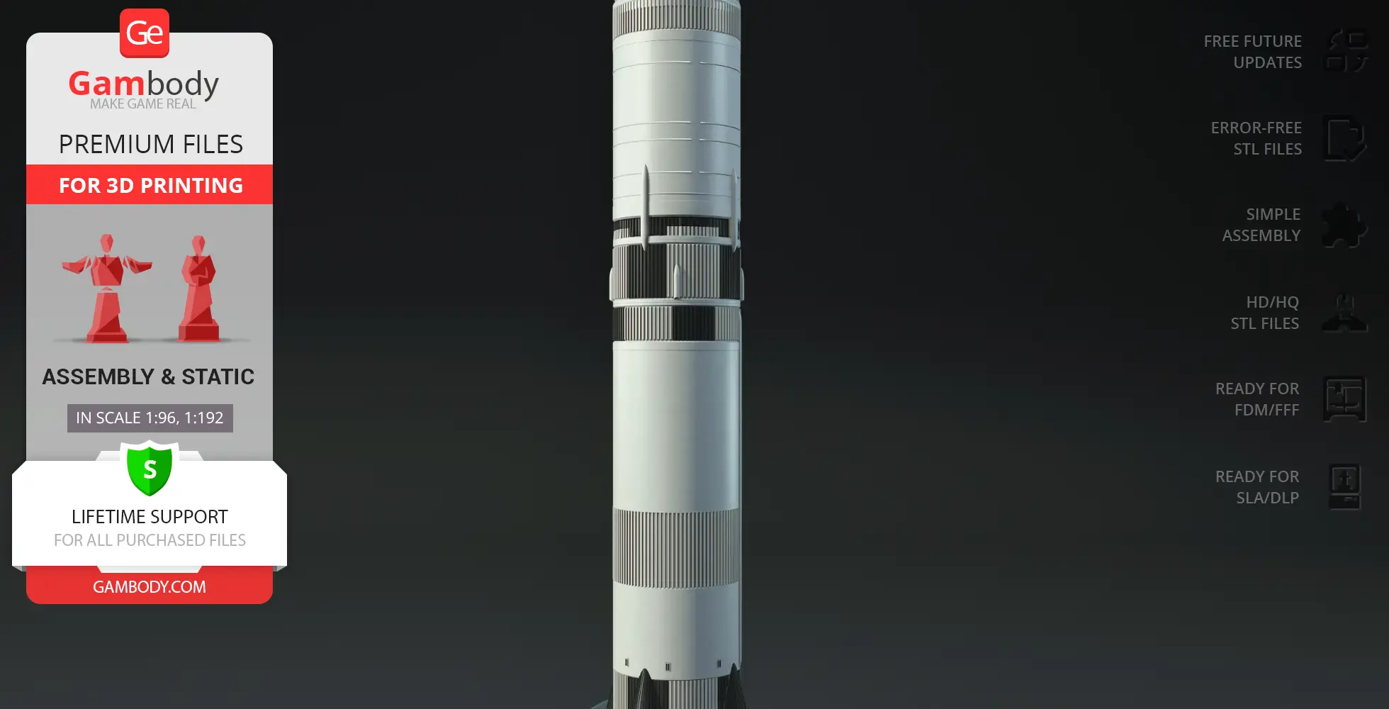
Before the Eagle could land on the Moon, the journey began with the mighty Saturn V Rocket Apollo 11 — the most powerful moon mission rocket ever built. On July 16, 1969, it launched the Apollo 11 spacecraft, carrying the Command Module Columbia and the Lunar Module Eagle toward the Moon. This legendary launch vehicle became the heart of the Apollo moon mission, marking humanity’s first step beyond Earth.
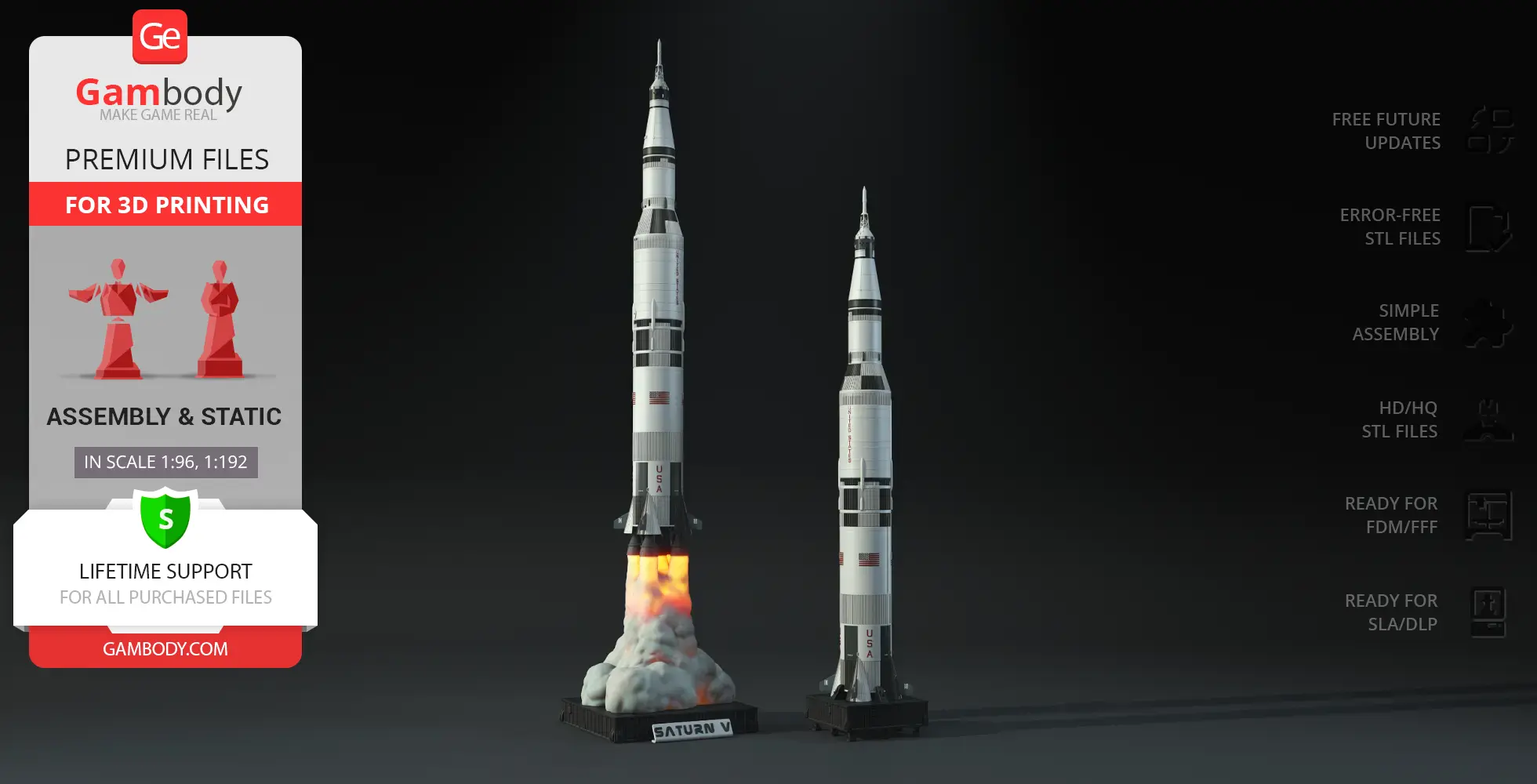
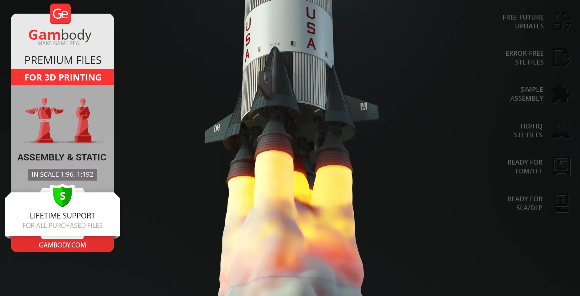
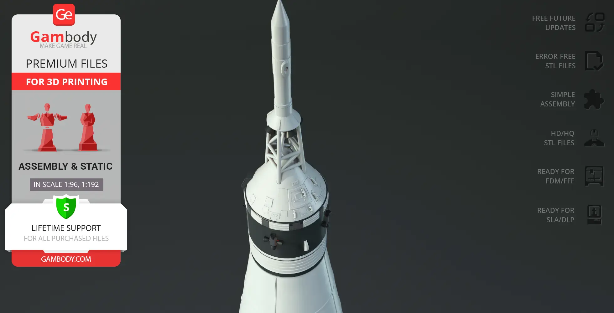
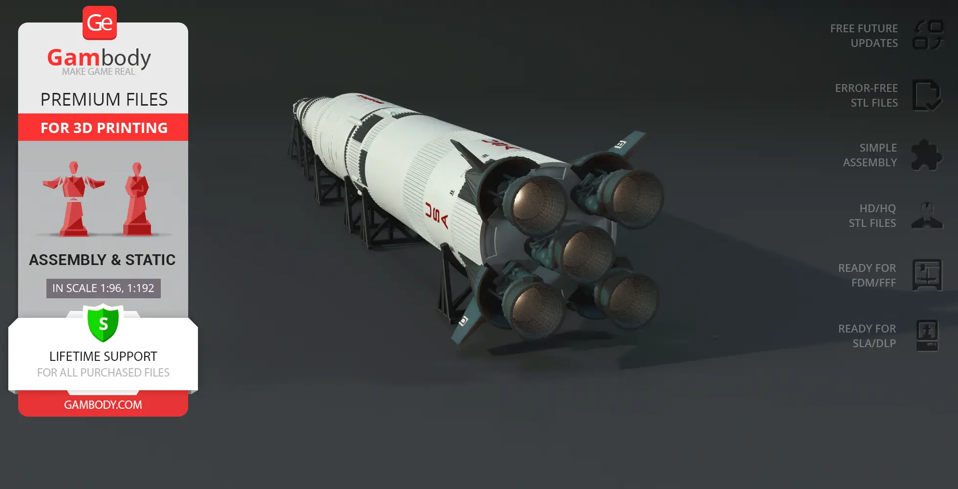
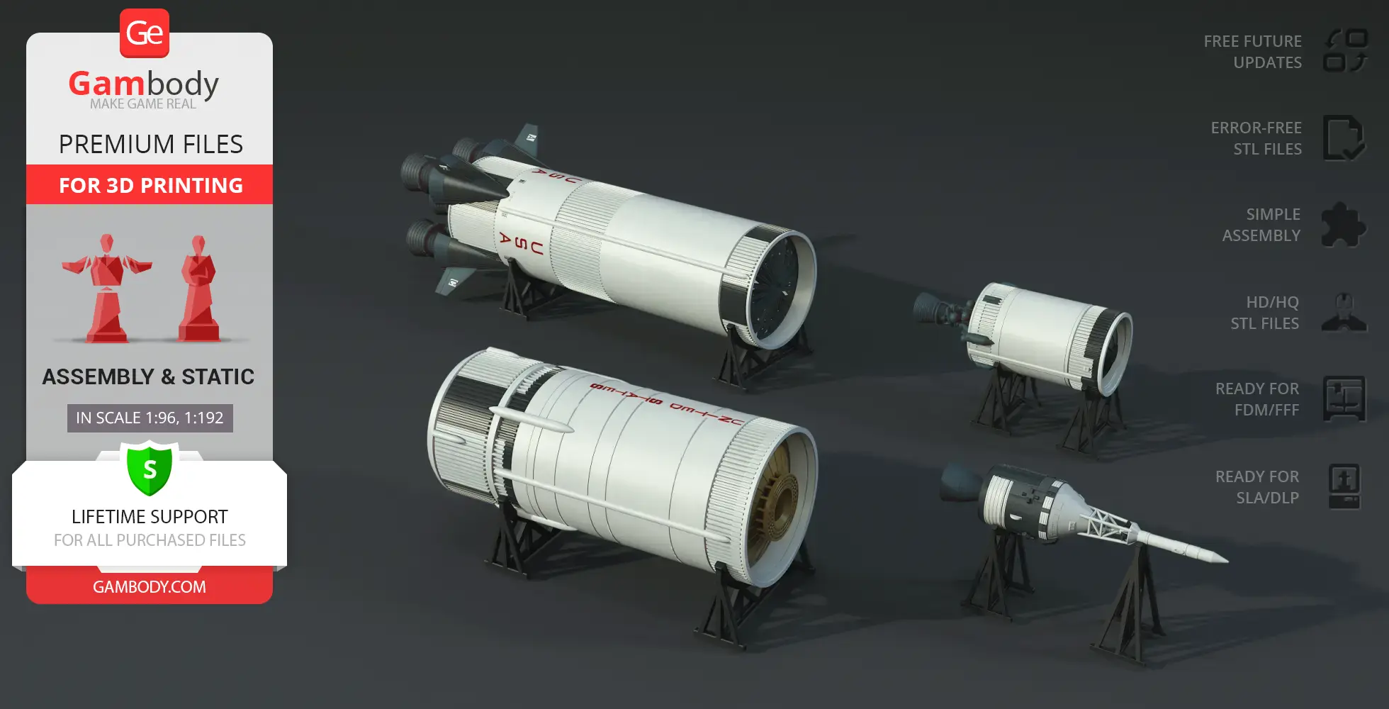
The Apollo 11 Saturn V Rocket 3D model recreates this engineering masterpiece with stunning precision. Every stage of the Saturn V space rocket, from its colossal F-1 engines to its signature black-and-white design, has been faithfully crafted for collectors and space enthusiasts. Presented as premium Apollo 11 Saturn V STL files, this 3D printed rocket model includes carefully optimized vehicle STL files for smooth printing and easy assembly.
Whether you’re a fan of historical 3D models, detailed spacecraft designs, or legendary launch vehicles, this Saturn V 3D model lets you relive the era of humanity’s greatest space achievements!
3D printing model features
Model-specific features:
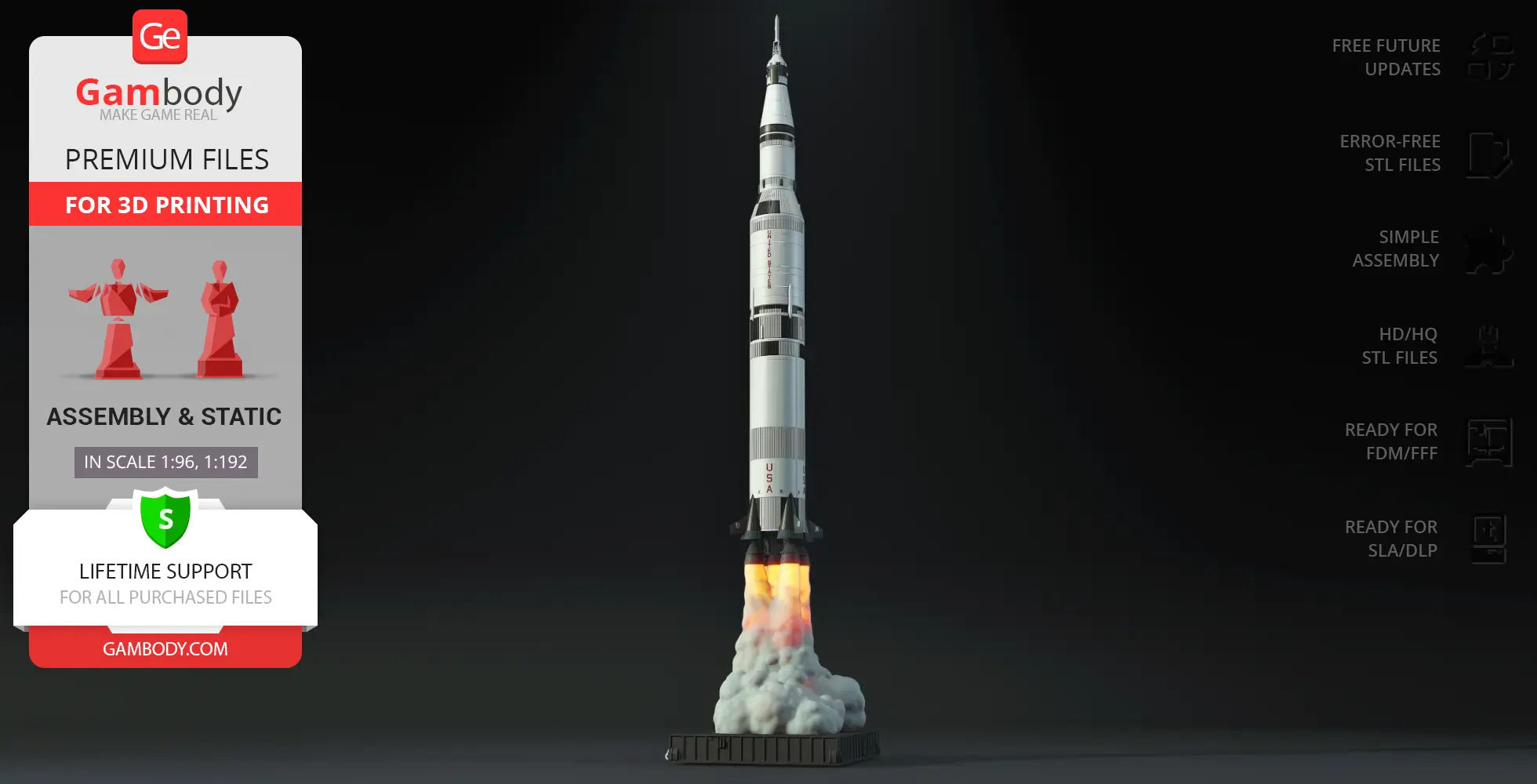
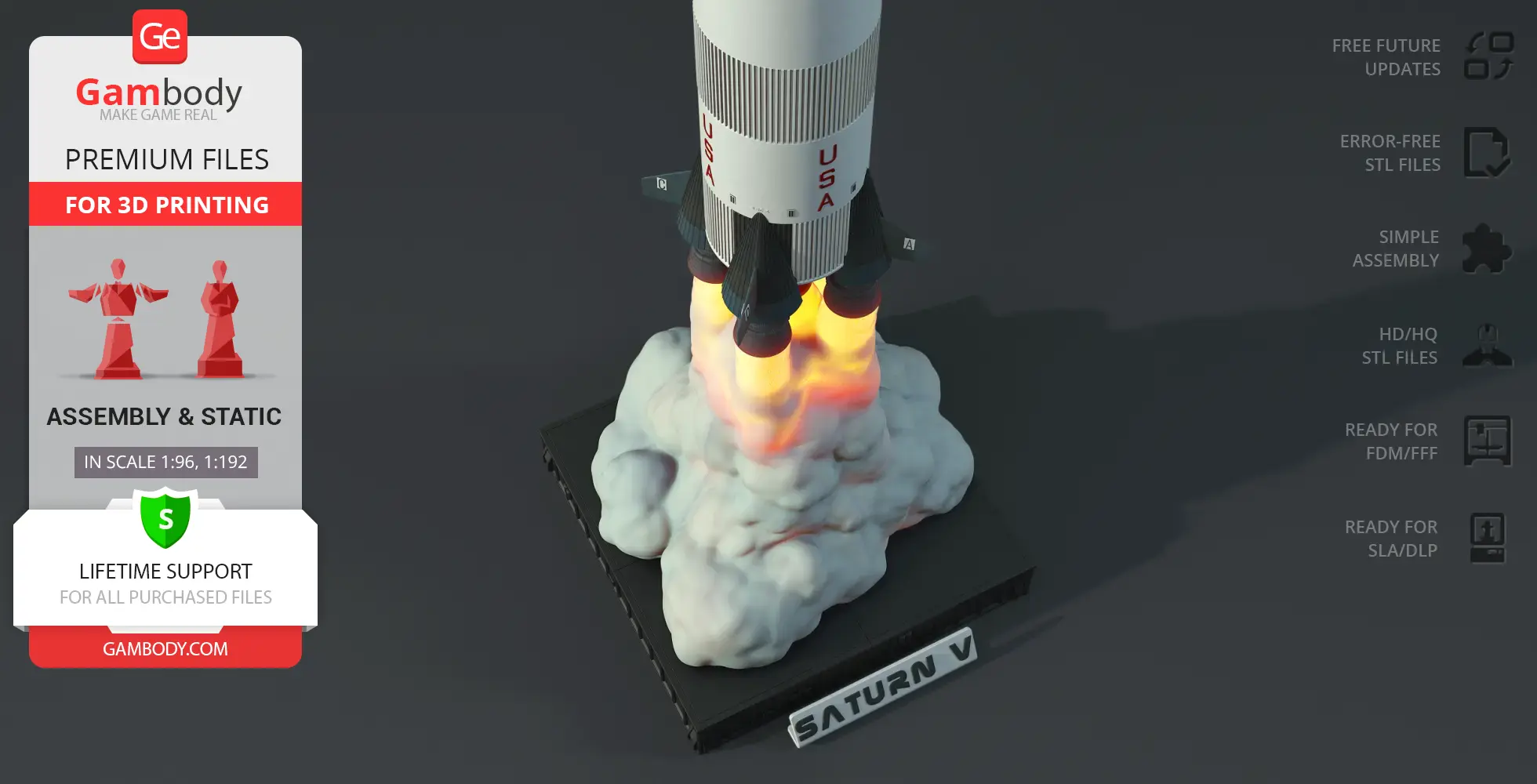
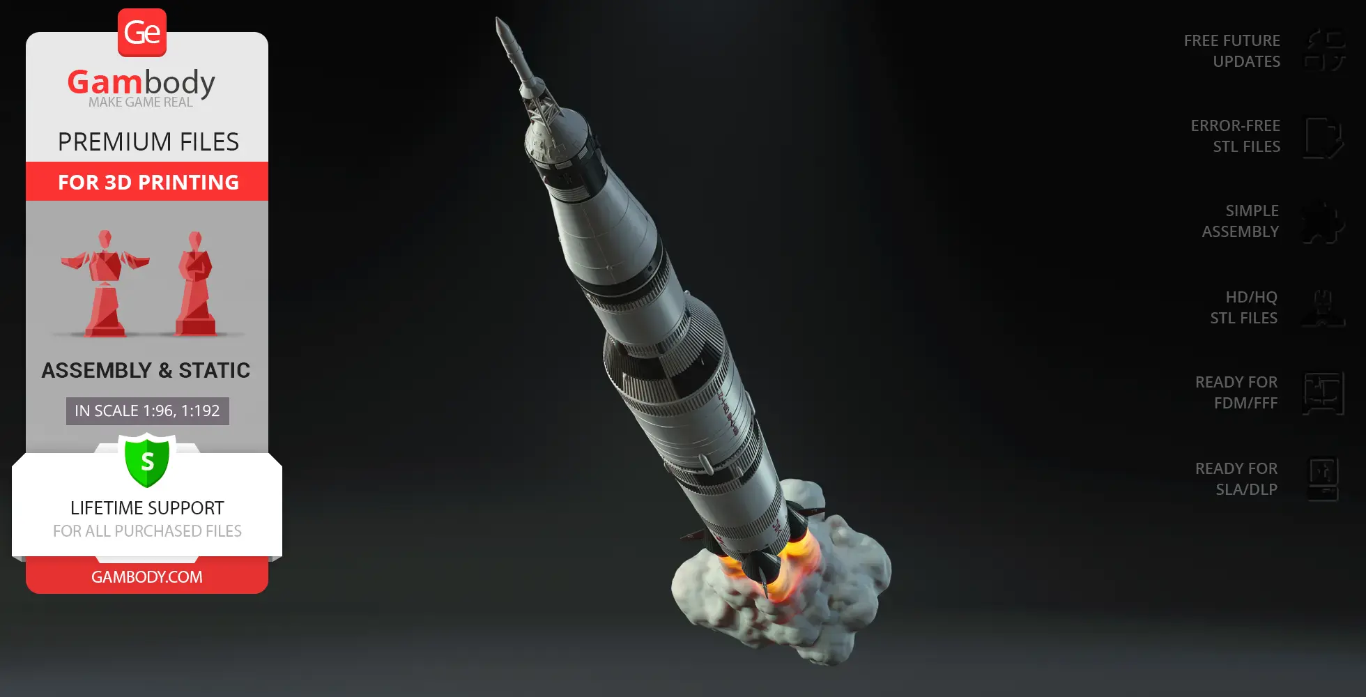
- This model captures the iconic launch vehicle of the Apollo 11 mission in high detail, making it a must-have for NASA fans and space collectors.
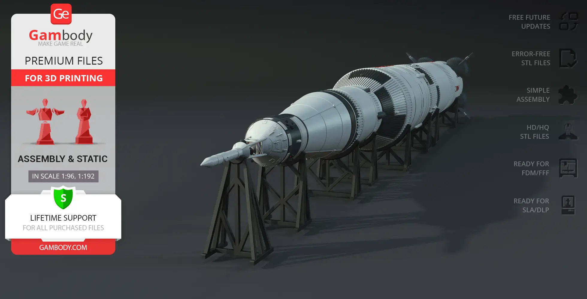
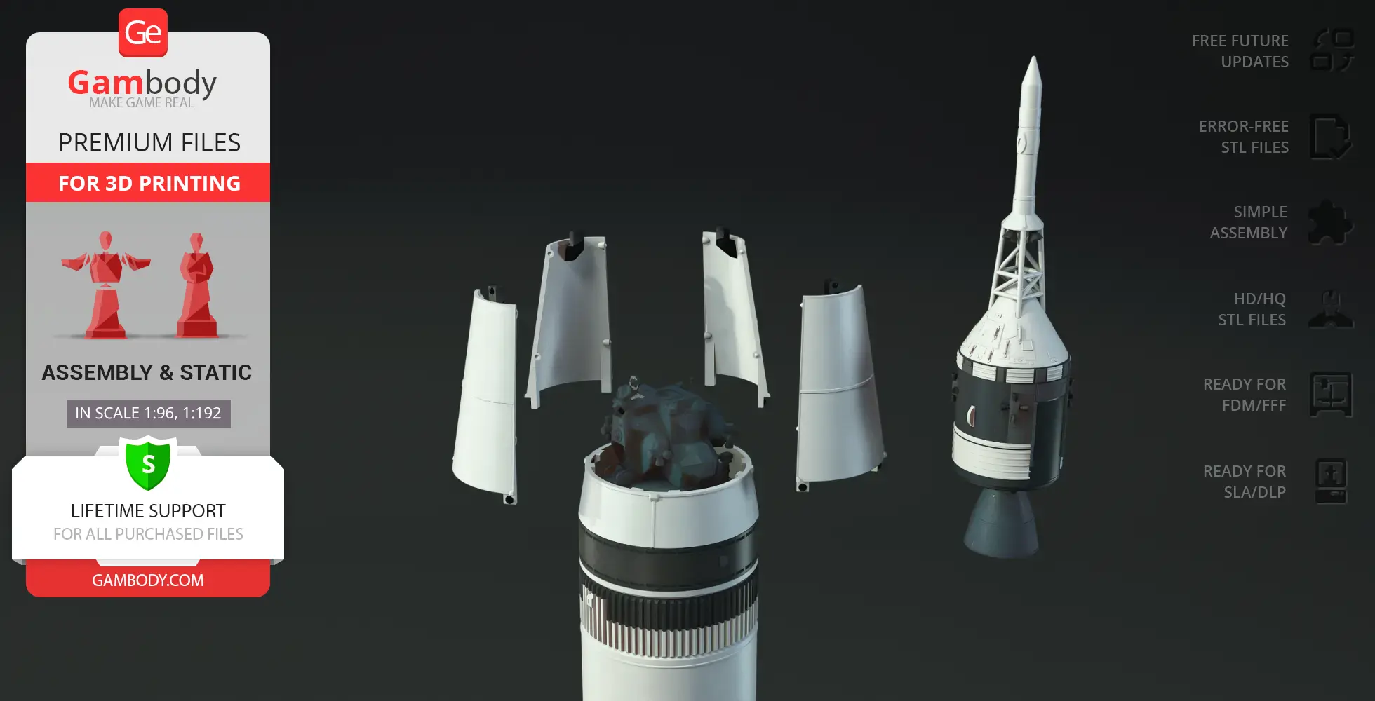
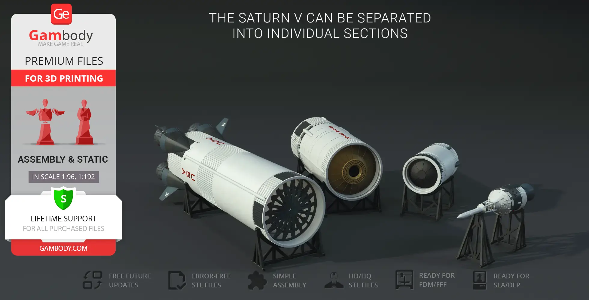
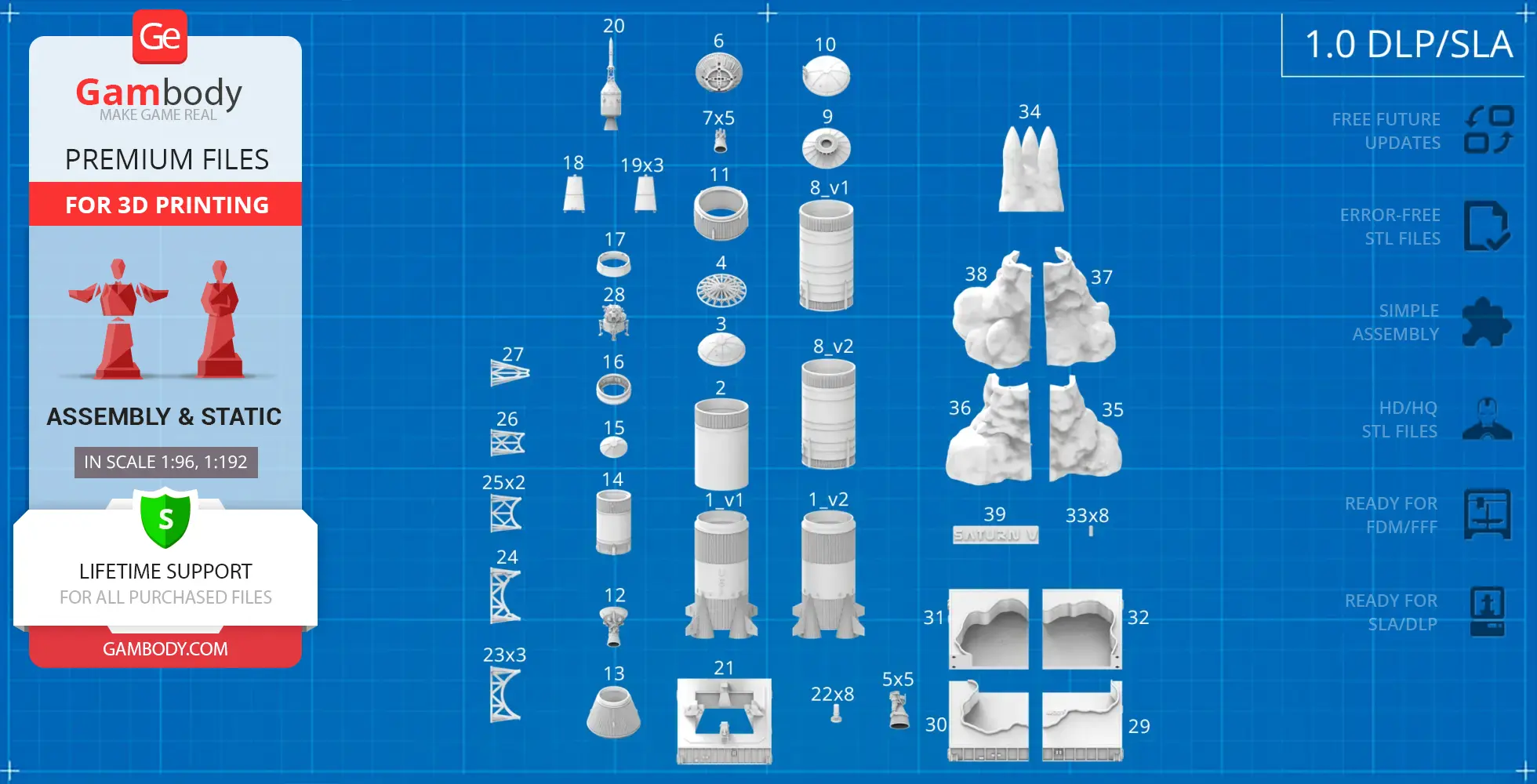
- The model can be disassembled into separate fuel tank sections for detailed display.
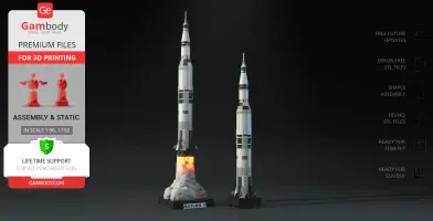
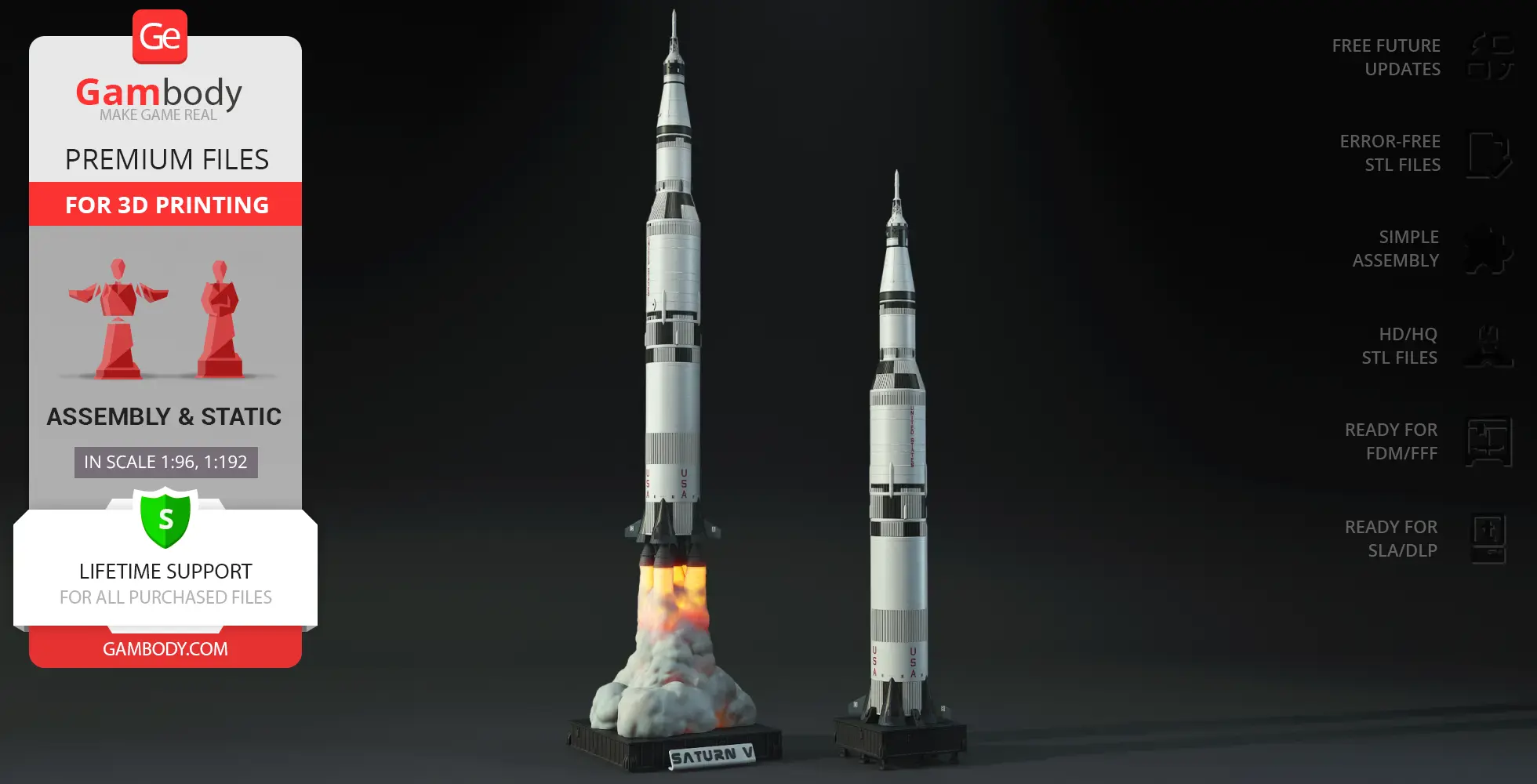
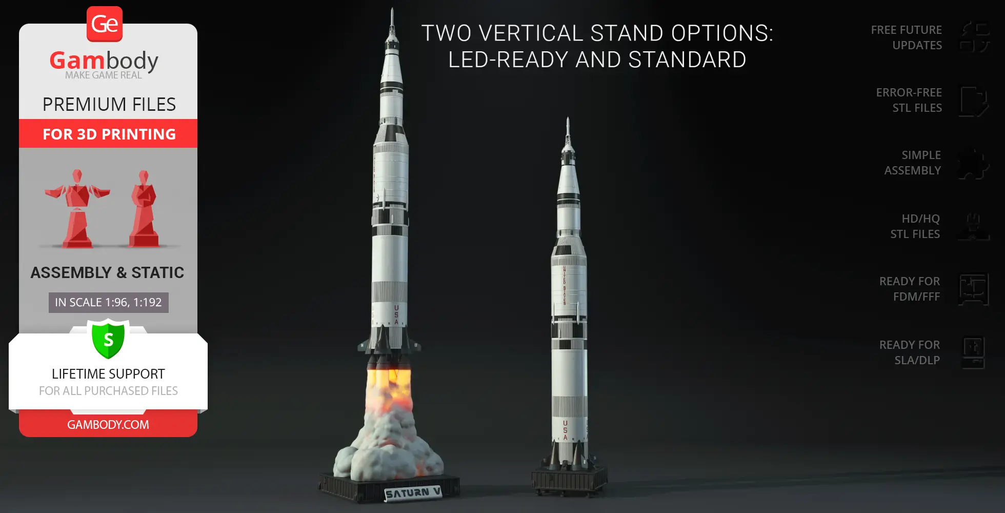
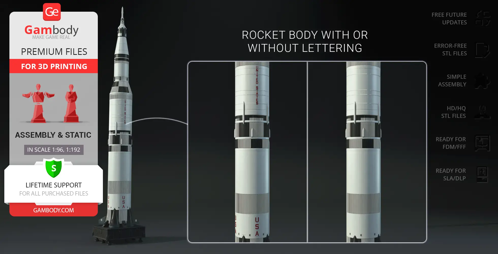
- Features two rocket body versions: with or without historical markings—and four first-stage variants: standard or LED-ready, each available with or without lettering.
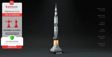
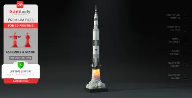
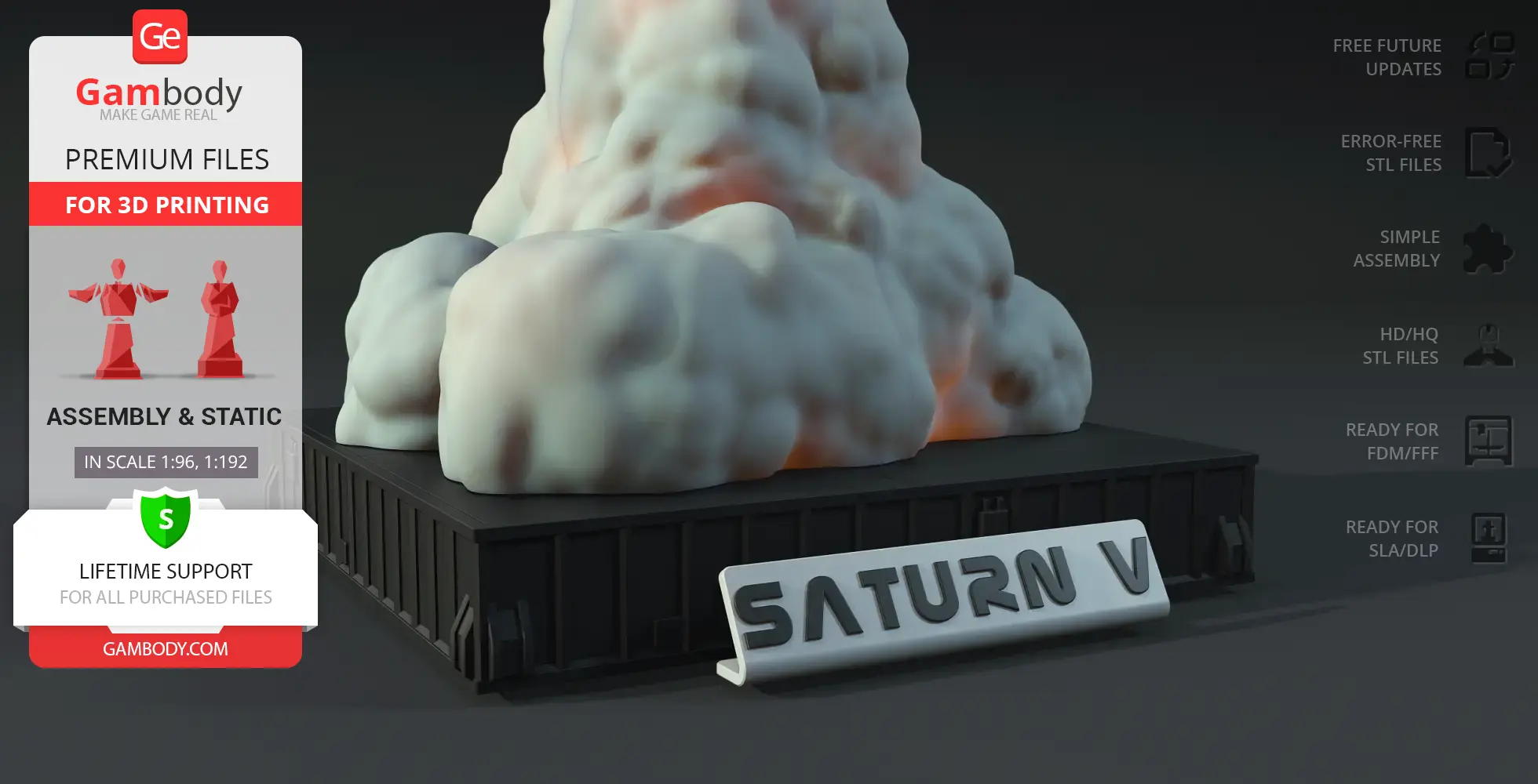
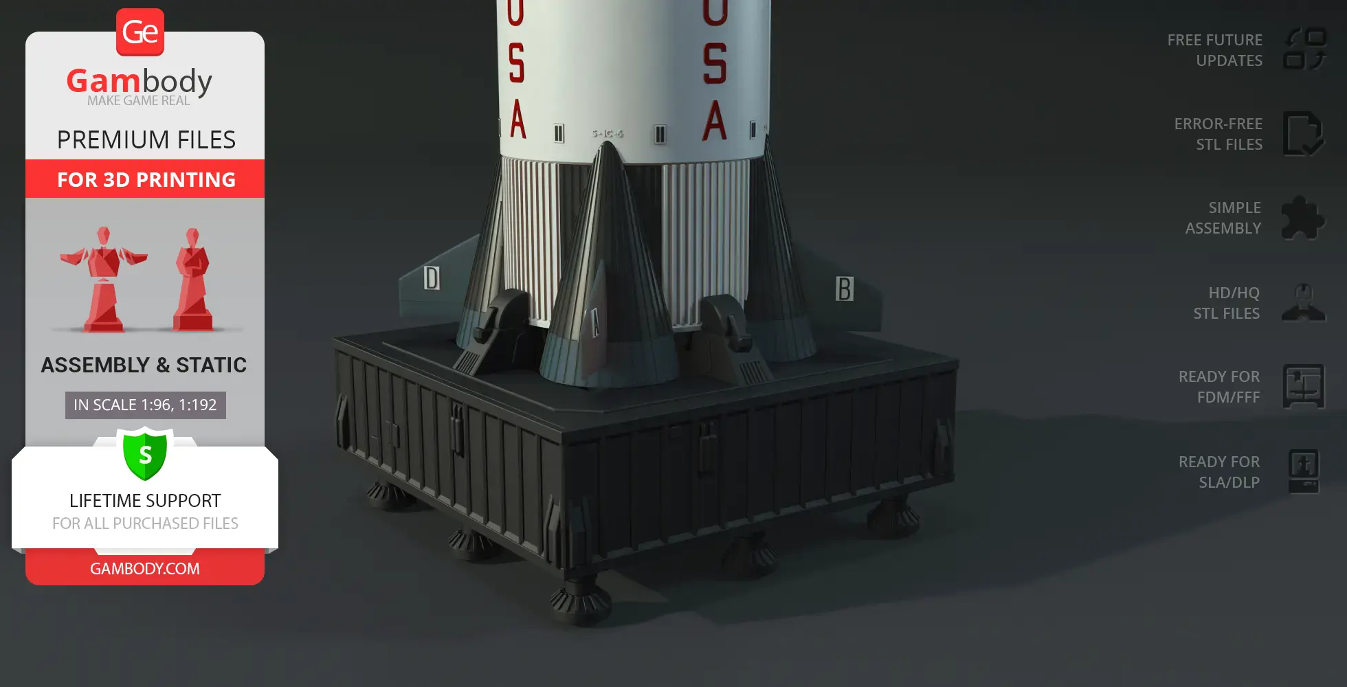
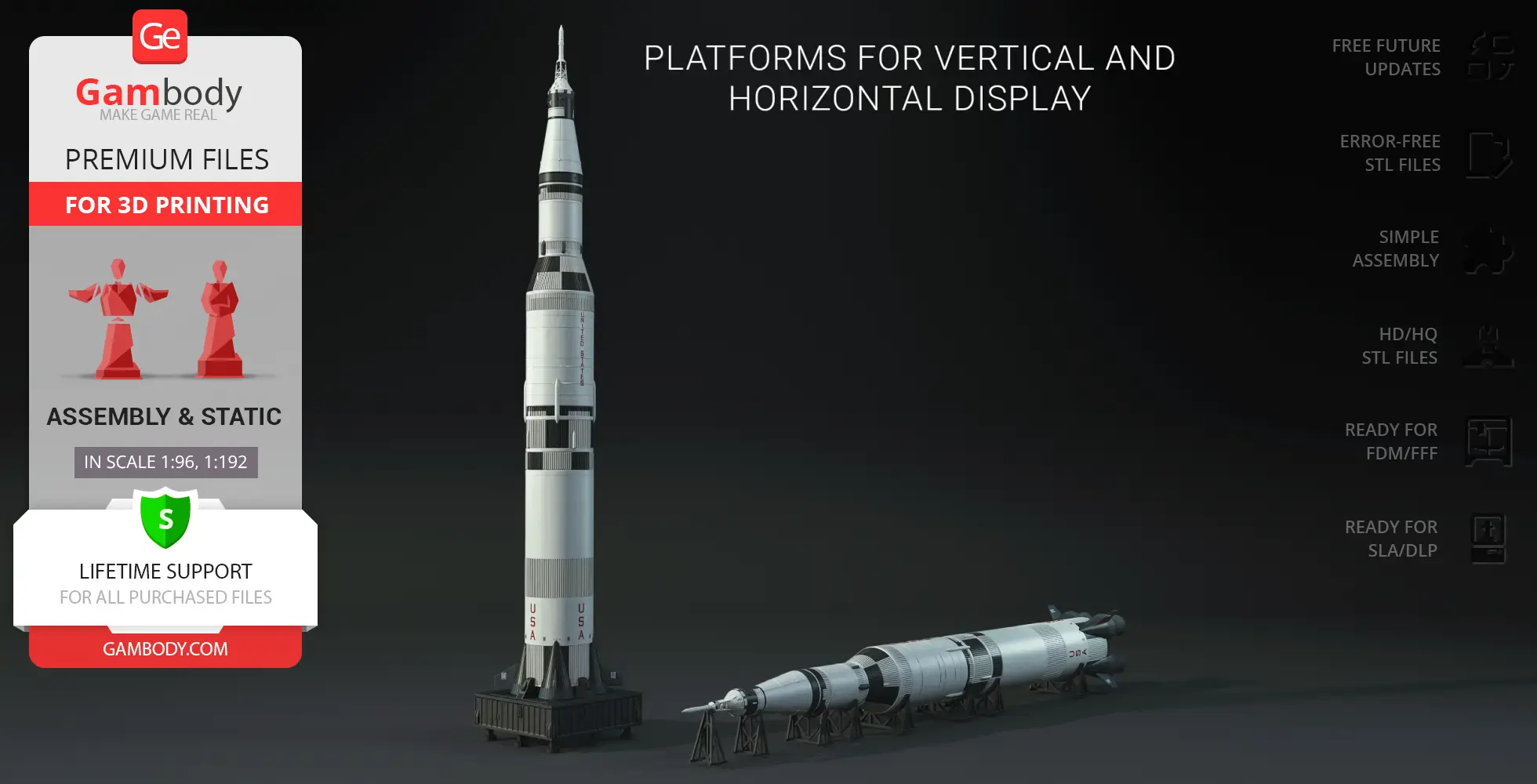
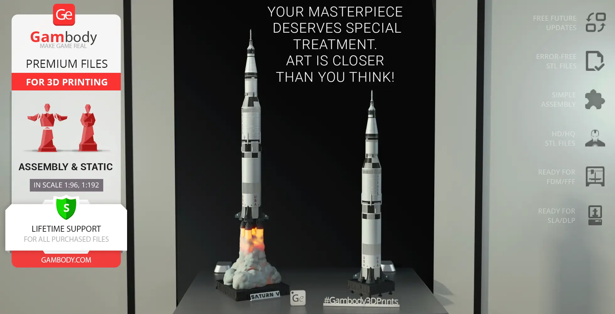
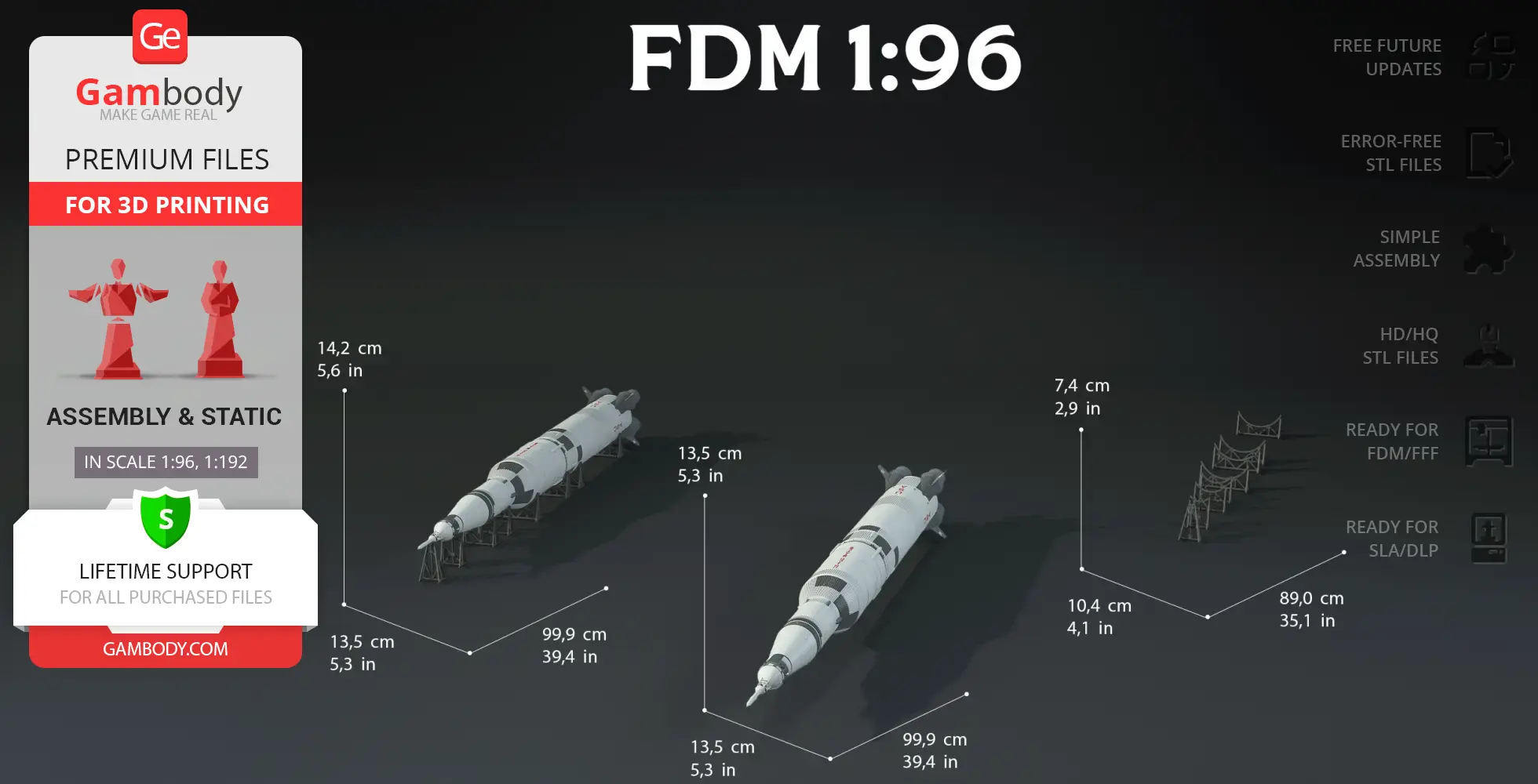
- Includes three platform options for vertical and horizontal display, letting you showcase the rocket in assembled or sectional diorama form.
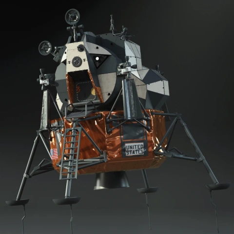
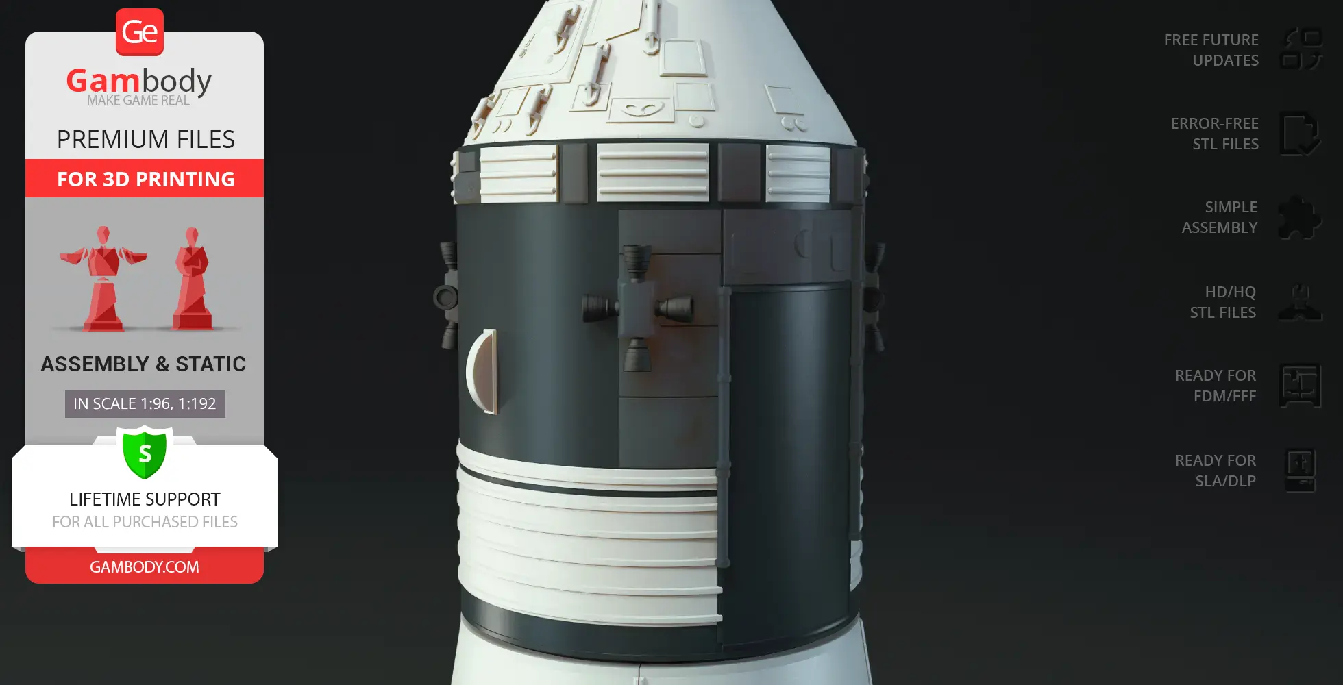
- A detachable upper stage opens to reveal the Lunar Module compartment, allowing the module to be removed or replaced for display.
- Comes with an optional transport cover for the second stage, designed for horizontal setups.
- Optimized for printing without painting—black parts are printed separately and attached afterward.
Printing & assembly details:
- Provided as error-free STL files compatible with most 3D printers;
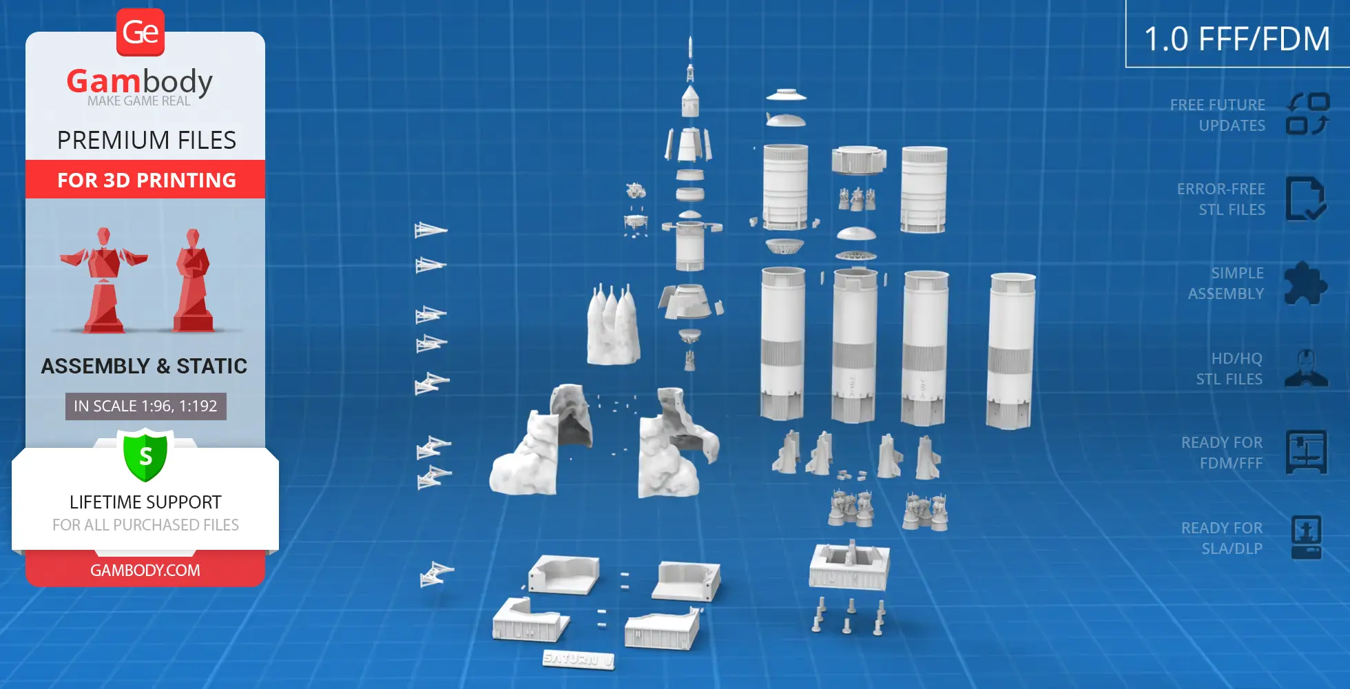
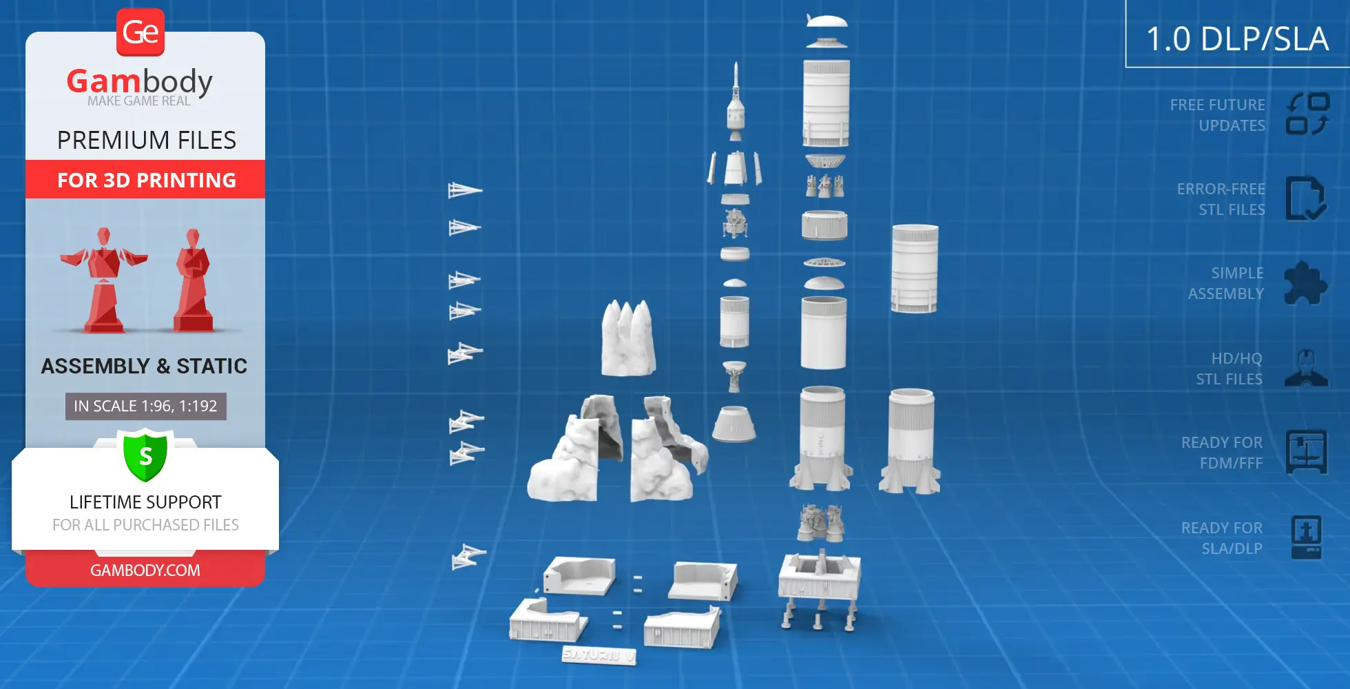
- Optimized part division minimizes support material and ensures smooth surface detail;
- The assembly parts in the FFF/FDM version come in the recommended print orientations for easy bed placement;
- Assembly manual in PDF and video formats is included for both FFF/FDM and DLP/SLA versions;
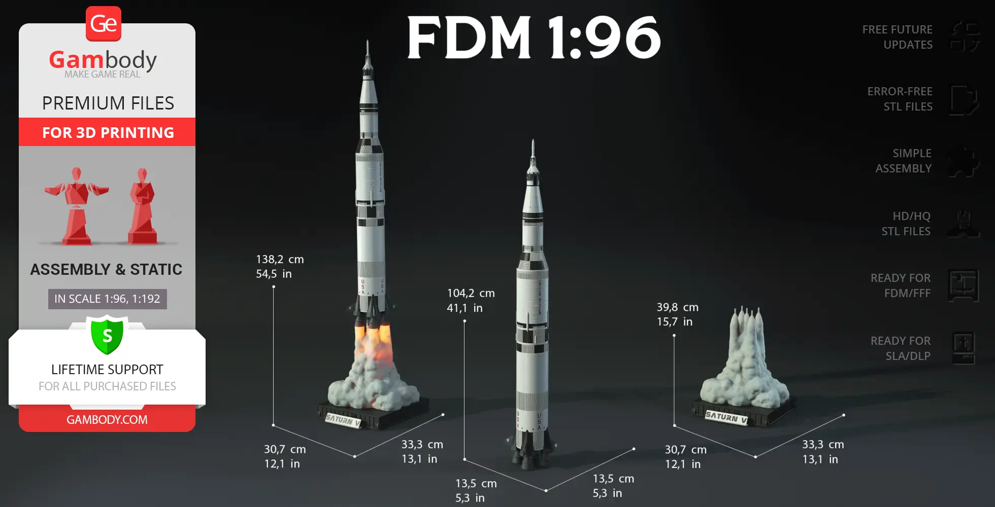
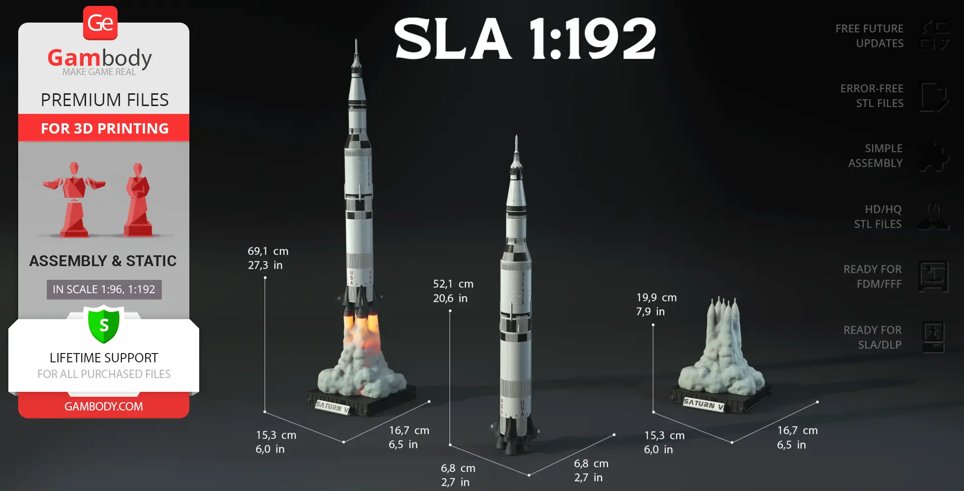
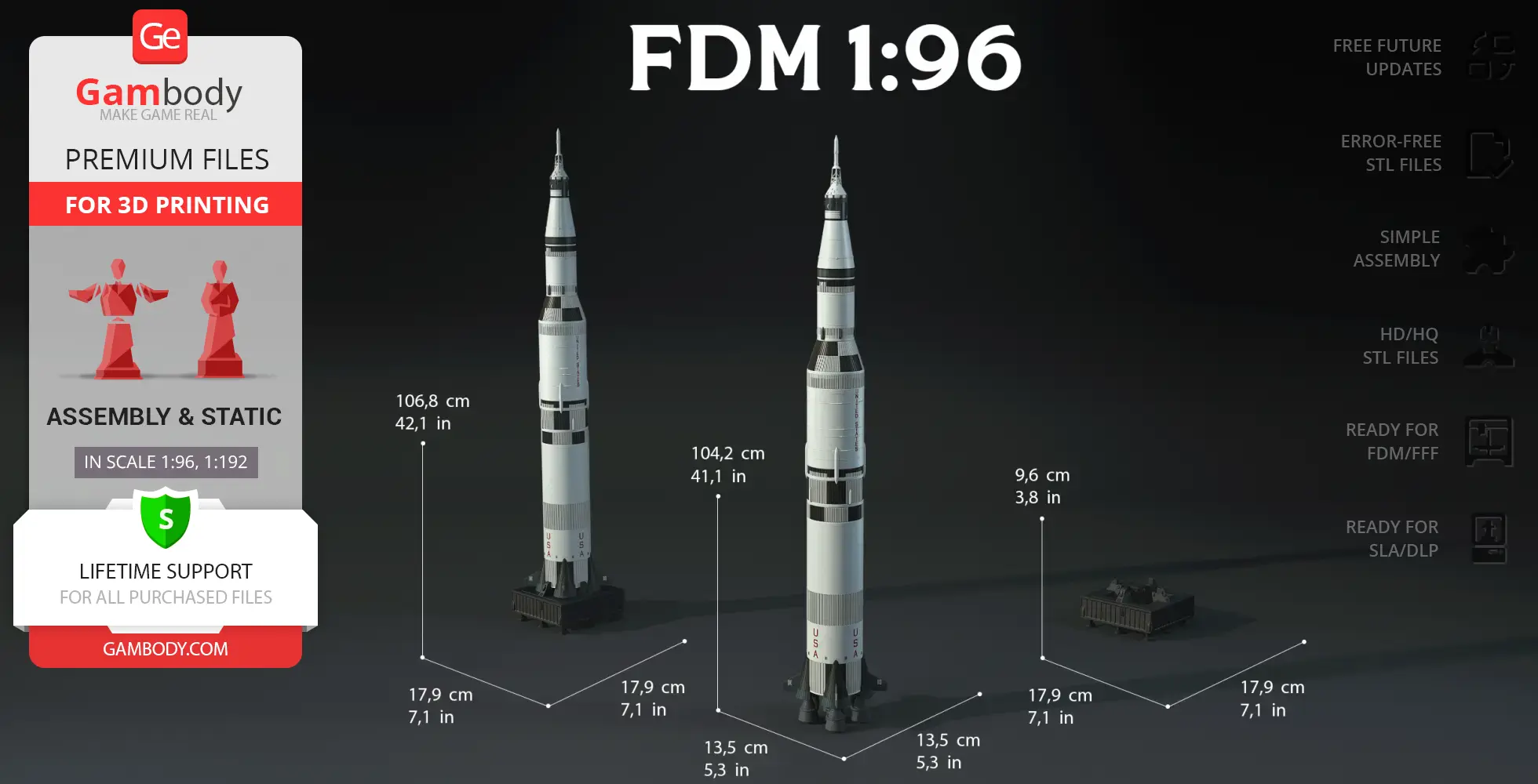
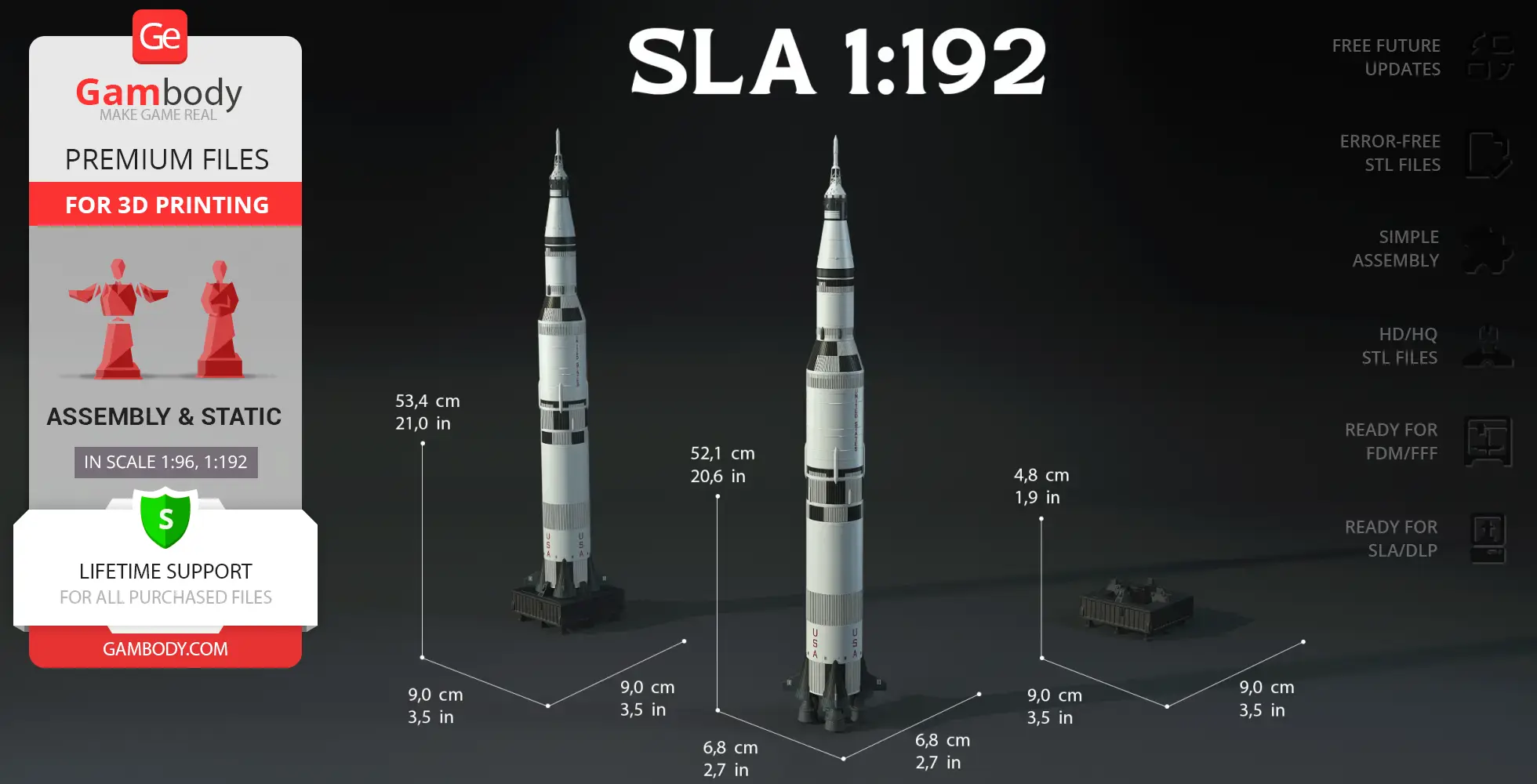
- The model is available in recommended scales of 1:96 for the FFF/FDM version and 1:192 for the DLP/SLA version.
What will you get after purchase?
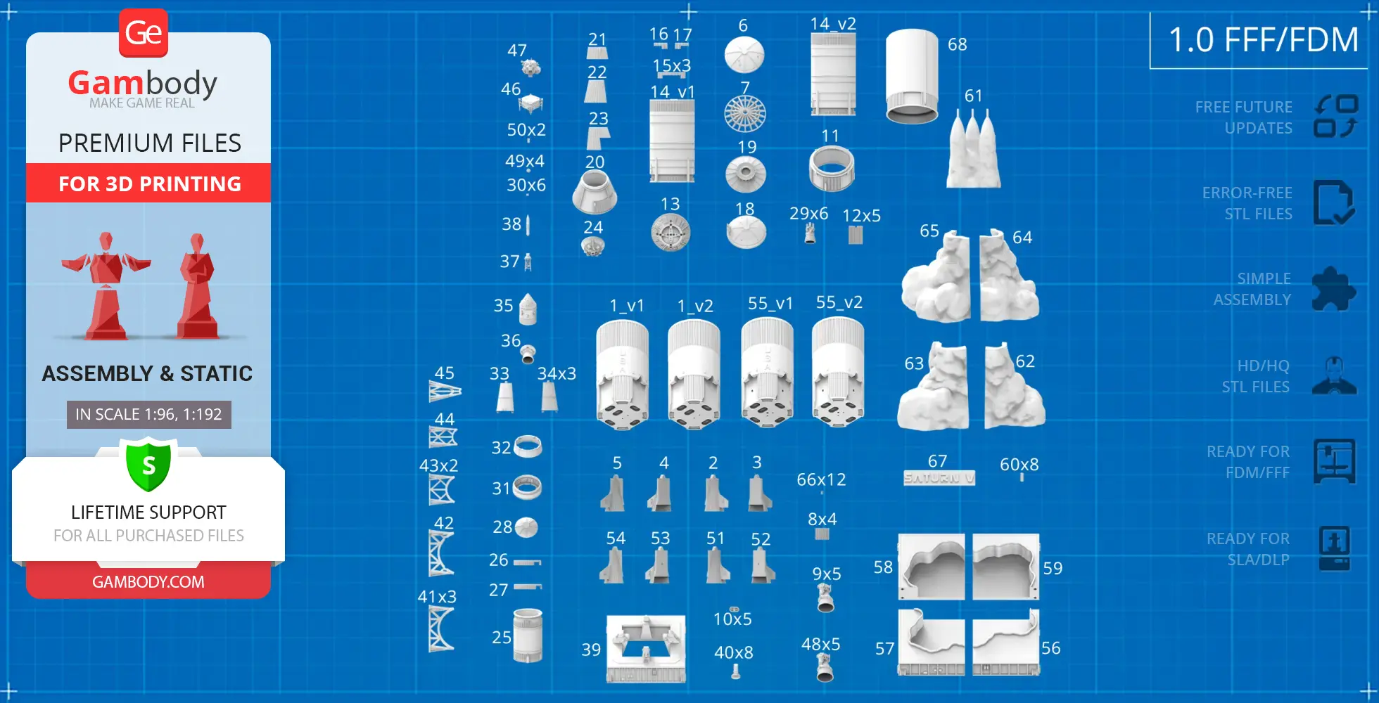
- 4 versions of Apollo 11 Saturn VSTL files for FFF/FDM and DLP/SLA — files for all versions are available for download after the purchase;
- STL files of high-poly Apollo 11 Saturn V model for 3D printing consist of 233 files;
- Sizes for:
- FFF/FDM Model Size: 135 mm wide, 1042 mm high, 135 mm deep;
- FFF/FDM Smoke Platform Size: 307 mm wide, 398 mm high, 333 mm deep;
- FFF/FDM Standard Platform Size: 179 mm wide, 96 mm high, 179 mm deep;
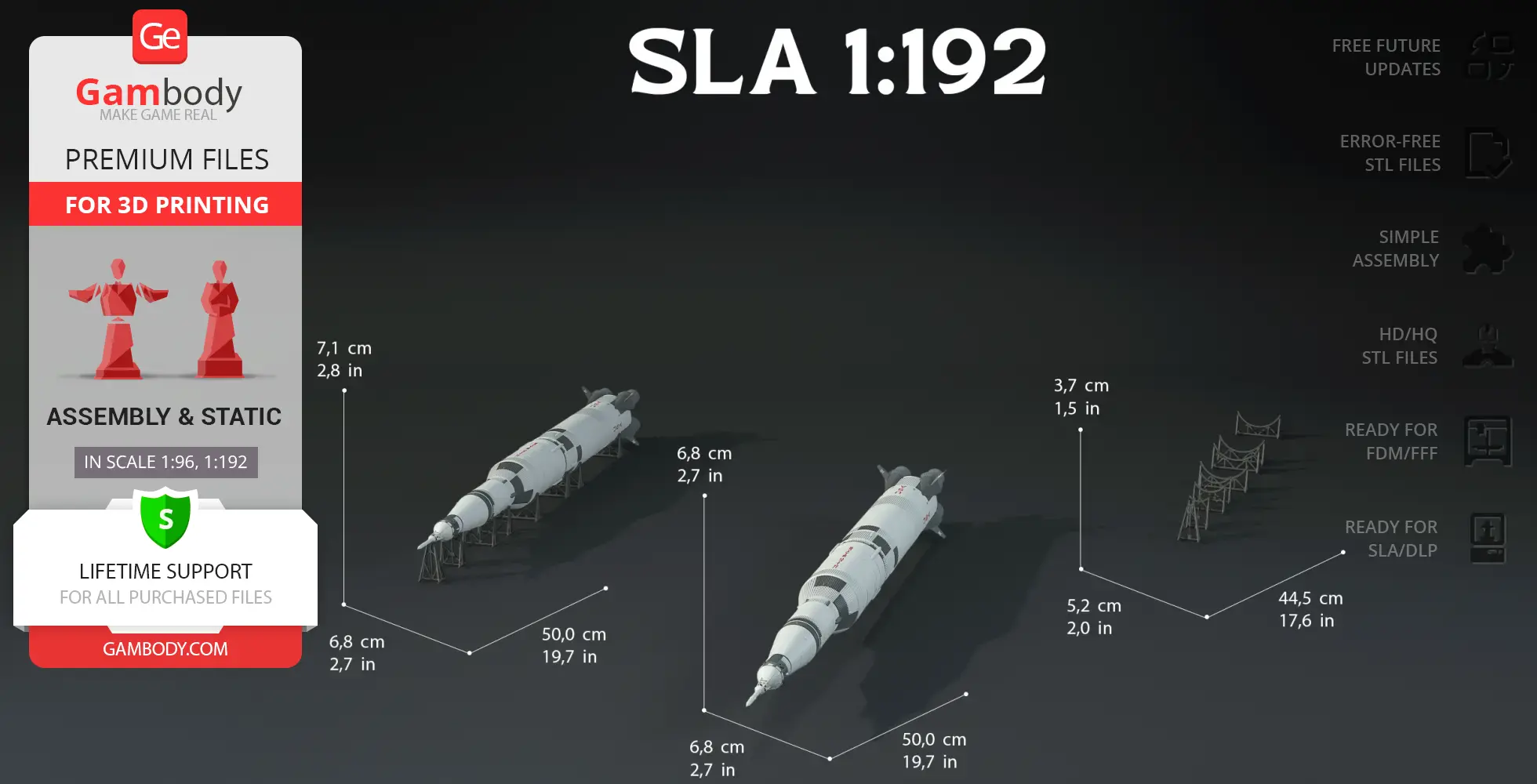
- DLP/SLA Model Size: 68 mm wide, 521 mm high, 68 mm deep;
- DLP/SLA Smoke Platform: 153 mm wide, 199 mm high, 167 mm deep;
- DLP/SLA Standard Platform: 90 mm wide, 48 mm high, 90 mm deep;
- Assembly Manual for 1.0 FFF/FDM and 1.0 DLP/SLA versions in PDF and video formats;
- Detailed settings that we provide as a recommendation for Bambu Studio, Cura, Orca Slicer, PrusaSlicer, Simplify3D, and Slic3r for the best print;
- Full technical support from the Gambody Support Team.
Average customer rating (1 reviews)
0
Ratings breakdown
Click a star rating to filter reviews
Overall experience
Level of detail in the model
0
Model cut quality and assembly guide
0
Clarity and accuracy of the model page
0
Level of detail in the model
2.5
Model cut quality and assembly guide
2.4
Clarity and accuracy of the model page
0.4
Come on Gambody - SORT THIS OUT
We’re glad to confirm that the updated assembly manual for version 1.1 is now completed and uploaded. You can download the PDF by re-downloading any file from the Source Files tab under version 1.1. The assembly instructions are included inside the ZIP archive.
To clarify the situation: version 1.1 of the model was released earlier to provide users with access to the improved files as soon as possible, while the full assembly documentation was still being finalized. The assembly materials for version 1.0 remained available during this time, but we recognize that they did not reflect the updated/modified files introduced in version 1.1.
In any case, we truly appreciate your patience and thank you for your feedback. It helps us improve how we roll out updates for complex models, and we’re committed to providing better coordination between file releases and documentation going forward. If you have any further questions or need help with the build, we’re here to assist.
At the moment, our available assembly video corresponds to version 1.0 of the model. As the newer version 1.1 was released recently with several improvements, the assembly manual is currently undergoing a full revision to reflect these changes. This is the reason for the discrepancies you’ve noticed between the part numbers in the video and your version 1.1 files.
Please be assured that updating the manual is a high priority for us. As soon as the revised instructions are finalized, they will be uploaded to the model page immediately.
In the meantime, if you have questions about a specific assembly step or need help identifying a particular part, please let us know – we are more than happy to provide direct assistance to keep your project moving forward.
Below you'll find detailed slicing settings for Bambu Studio 2.0+, Orca Slicer 2.0+, UltiMaker Cura 5.0+, PrusaSlicer 2.0+, Slic3r 1.3+, Simplify3D 5.0+ to help you get the best results when printing this model. These settings are optimized specifically for this 3D model, but please note they may need slight adjustments depending on your printer or filament. When in doubt, refer to your printer's user manual.
To avoid printing issues and achieve the best quality, we highly recommend applying the following settings:
For better quality use 0.12 mm layer height, for fast printing use 0.2 mm layer height. For pins and the Ge connectors, use 0.2 layer height.
120-150% of your Layer Height
But you can paint the seam if you want.
You have to calibrate this parameter
You have to calibrate this parameter
You have to calibrate this parameter
For pins and power elements of the structure, such as the vehicle frame, use 3 loop
Disabled for vehicles and enabled for characters
For 0,2 Layer Height
The parameters in this tab vary greatly, it all depends on the quality of your printer. For example, if you have a classic Ender3, stick to the minimum parameters, but if you have a newer printer, for example Anycubic cobra 3 v2, you can select the maximum recommended values
Settings for advanced users, change these parameters only if you have sufficient 3D printing expertise
Enable this parameter if your model requires supports
We also recommend placing and removing supports manually in some places using special button
1-2 loops for more thick support
Top Z distance = 1-1.3 layer Height. If the supports are hard to remove, try increasing this setting by 0.1-0,4 mm
Bottom Z distance = 1-1.3 layer Height. If the supports are hard to remove, try increasing this setting by 0.1-0,4 mm
You have to calibrate this parameter which one is better for your filament
Increase this parameter if the supports are hard to remove from walls
For PLA and PETG filament types
5-8 mm is optional for small prints that have bad adhesion to the build plate
You have to calibrate this parameter
Read the description on your filament roll
Read the description on your filament roll and increase this parameter for fast printers
Read the description on your filament roll and increase this parameter for fast printers
For better quality use 0.12 mm layer height, for fast printing use 0.2 mm layer height. For pins and the Ge connectors, use 0.2 layer height.
120-150% of your Layer Height
But you can paint the seam if you want.
0.01-0.05 You have to calibrate this parameter
0.01-0.05 You have to calibrate this parameter
0.1-0.2 You have to calibrate this parameter
For pins and power elements of the structure, such as the vehicle frame, use 3 loop
Disabled for vehicles and ships, enabled for characters
For 0,2 Layer Height
For 0,2 Layer Height
The parameters in this tab vary greatly, it all depends on the quality of your printer. For example, if you have a classic Ender3, stick to the minimum parameters, but if you have a newer printer, for example, Anycubic Kobra 3 Or Bambulab A1, you can select the maximum recommended values.
Settings for advanced users, change these parameters only if you have sufficient 3D printing expertise
Enable this parameter if your model requires supports
We also recommend placing and removing supports manually in some places using special button
Top Z distance = 1-1.3 layer Height. If the supports are hard to remove, try increasing this setting by 0.1-0,4 mm
Bottom Z distance = 1-1.3 layer Height. If the supports are hard to remove, try increasing this setting by 0.1-0,4 mm
Increase this parameter if the supports are hard to remove from walls
For PLA and PETG filament types
5-8 mm is optional for small prints that have bad adhesion to the build plate
Read the description on your filament roll
Read the description on your filament roll and increase this parameter for fast printers
You have to calibrate this parameter
Read the description on your filament roll and increase this parameter for fast printers
Read the description on your filament roll
This field is filled in according to your printer specifications when you add it to the slicer.
You can add custom G-code here for the start and end of the print. However, be careful - this is for advanced users only!
You have to calibrate your printer using Ge retraction test models
Retraction Length: For direct-drive setups use 0.5 mm to 2.5 mm; for Bowden extruders use 5 to 7 mm
This is how fast the filament is pulled back—40-60 mm/s for direct drive and 30-50 mm/s for Bowden setups.
You have to calibrate this parameter: Reduce it until the printer starts to hit the parts with the nozzle during printing, then increase it by 0.2.
For better quality use 0.12 mm layer height, for fast printing use 0.2 mm layer height. For pins and the Ge connectors, use 0.2 layer height.
120-150% of your Layer Height
To increase the strength of the print parts, use wall line count: 3
For pins and connectors use 50% Infill
These parameters are for standard PLA plastic. If you are using a different type of plastic, check the printing temperature recommended by the manufacturer. Also, read the description on your filament spool. For fast printers, add +30 °C to the current parameters.
The parameters in this tab vary greatly, it all depends on the quality of your printer. For example, if you have a classic Ender3, stick to the minimum parameters, but if you have a newer printer, for example Anycubic cobra 3 v3, you can select the maximum recommended values
Settings for advanced users, change these parameters only if you have sufficient 3D printing expertise.
You need to calibrate this parameter using Gambody test models. These values are average values for a Direct Drive extruder; for a Bowden extruder, the values should be increased.
You need to calibrate this parameter using Gambody test models. These values are average values for a Direct Drive extruder; for a Bowden extruder, the values should be increased.
Use this value other than 0 if your nozzle catches on the internal infill during travel moves. Try to keep this value as low as possible in height.
Use normal supports to support large, straight surfaces (most mechanical or technical parts).
You have to calibrate this parameter according to the capabilities of your printer and your filament, using a Gambody test models.
Use 1 instead of 0 if your supports are thin and tall. They will be harder to remove, but much stronger.
Top Z distance = 1-1.3 layer Height. If the supports are hard to remove, try increasing this setting by 0.1-0,4 mm
Increase this parameter if the supports are hard to remove from walls
Use tree supports to support complex objects, such as characters.
You have to calibrate this parameter according to the capabilities of your printer and your filament, using a Gambody test models.
Top Z distance = 1-1.3 layer Height. If the supports are hard to remove, try increasing this setting by 0.1-0,4 mm
Increase this parameter if the supports are hard to remove from walls
Use a skirt for all parts when printing on outdated printers.
Use a brim when printing thin but tall parts, as well as parts with a small bed adhesion area.
For better quality use 0.12 mm layer height, for fast printing use 0.2 mm layer height. For pins and the Ge connectors, use 0.2 layer height.
120-150% of your Layer Height
for 0.2 Layer Height
But you can paint the seam if you want.
(for PLA and PETG)
(5-8 mm is optional for small prints that have bad adhesion to the build plate)
Enable this parameter if your model requires supports
(45-50 degree)You have to calibrate this parameter according to the capabilities of your printer
and your filament, using a Gambody test models.
Top contact Z distance = 1-1.3 layer Height. If the supports are hard to remove, try
increasing this setting by 0.1-0,4 mm
Top contact Z distance = 1-1.3 layer Height. If the supports are hard to remove, try
increasing this setting by 0.1-0,4 mm
Increase this parameter if the supports are hard to remove from walls
The parameters in this tab vary greatly, it all depends on the quality of your printer. For example, if you have a classic Ender3, stick to the minimum parameters, but if you have a newer printer, for example Anycubic cobra 3 v3, you can select the maximum recommended values
Settings for advanced users, change these parameters only if you have sufficient 3D printing expertise. Use the minimum value for outdated printers without acceleration calibration, and the maximum value for modern printers if you need it.
These settings only work for 3D printers with multiple extruders
You can try setting all parameters in this section, except the First layer, to values between 0.75% of your nozzle diameter and 1.25% of your nozzle diameter. Adjusting them will help you work out the optimal parameters for the best quality for your print. As for the First layer, you can set it to 150% of the diameter of your nozzle for better adhesion to the build plate (for a nozzle with a diameter of 0.4 mm, the First layer extrusion width can be from 0.3 mm to 0.5 mm)
For better printing quality you have to calibrate this parameter using Gambody test model.
Check your filament manufacturer's temperature recommendations on the spool.
Cooling parameters depends on the material you use for printing.
*for PLA
For better quality use 0.12 mm layer height, for fast printing use 0.2 mm layer height. For pins and the Ge connectors, use 0.2 layer height.
120-150% of your Layer Height
For 0.12 Layer Height
For 0.12 Layer Height
For pins and connectors use 50% Infill
Use skirt for outdated 3d printers
(5-8 mm is optional for small prints that have bad adhesion to the build plate)
Enable this parameter if your model requires supports
(45-60 degree)You have to calibrate this parameter according to the capabilities of your printer and your filament, using a Gambody test models
Contact Z distance = 1-1.3 layer Height. If the supports are hard to remove, try increasing this setting by 0.1-0,4 mm
The parameters in this tab vary greatly, it all depends on the quality of your printer. For example, if you have a classic Ender3, stick to the minimum parameters, but if you have a newer printer, for example Anycubic cobra 3 v3, you can select the maximum recommended values
Settings for advanced users, change these parameters only if you have sufficient 3D printing expertise. Use the minimum value for outdated printers without acceleration calibration, and the maximum value for modern printers if you need it.
You have to calibrate this parameter from 0.9 to 1.1 according to the capabilities of your printer and your filament, using a Gambody test models.
Check your filament manufacturer's temperature recommendations on the spool.
Cooling parameters depends on the material you use for printing.
Calibrate this value if you need to reduce or improve the adhesion between the plastic and the heat bed
Your current nozzle diameter
You need to calibrate this parameter using Gambody test models. These values are average values for a Direct Drive extruder; for a Bowden extruder, the values should be increased.
Your current nozzle diameter
You have to calibrate this parameter using Gambody test models.
You need to calibrate this parameter using Gambody test models. These values are average values for a Direct Drive extruder; for a Bowden extruder, the values should be increased.
For better quality use 0.12 mm layer height, for fast printing use 0.2 mm layer height. For pins and the Ge connectors, use 0.2 layer height.
For 0,2 Layer Height
For 0,2 Layer Height
To increase the strength of the print parts, use Outline Perimeters: 3
You can enable this parameter to print rounded or spherical models, as well as character models.
Use this option only if your parts are too tight. but better calibrate your printer extrusion
Use this option only if your parts are too tight. but better calibrate your printer extrusion
Use 2 and more if you want to create skirt instead brim
1-2 for skirt and 10-20 for brim
Use for wipe nozzle if you need
Use For ABS filament
For pins and connectors use 50% Infill
Top Z distance = 1-1.3 layer Height. If the supports are hard to remove, try increasing this setting by 0.1-0,4 mm
Calibrate your filament and detect optimal temperature for it
Average temperature for PLA filament
The parameters in this tab vary greatly, it all depends on the quality of your printer. For example, if you have a classic Ender3, stick to the minimum parameters, but if you have a newer printer, for example Anycubic cobra 3 v3, you can select the maximum recommended values
Settings for advanced users, change these parameters only if you have sufficient 3D printing expertise.
DLP/SLA
- Updated version featuring a more canonical design and historical accuracy;
- Optimized for ease of painting with recessed boundaries on engine fairings;
- Includes separated stabilizers and updated black roll patterns across the 1st and 2nd stages;
- Enhanced with flag texture and corrected USA/United States lettering positions;
- Includes all 1.0 Version features: standard and LED-ready stage options, interior for the Lunar Module, and three display stand variants;
- The assembly parts are connected using specially designed integrated connectors that fit securely into the corresponding slots. Optionally, for added strength and rigidity, the static connections can be glued together.
FFF/FDM
- Updated version featuring a more canonical design and historical accuracy;
- Optimized for multi-color printing and easy slicer-based painting with recessed grooves on engine fairings;
- Includes separated stabilizers (with/without lettering) and removable black stripes for the lower hull;
- Refined USA/United States markings, added flag texture, and updated black roll patterns on the S-IC and S-II stages for true-to-life precision;
- Relocated external conduits;
- Includes all Version 1.0 features: standard and LED-ready first-stage options, detachable upper section for the Lunar Module, and three display stand variants (static, LED-flame, and horizontal diorama);
- The assembly parts are connected using specially designed integrated connectors that fit securely into the corresponding slots.
DLP/SLA
Two body versions: with and without lettering; Four first-stage options: with or without lettering, available in both standard and LED-ready versions; Three display stand options: static, smoke-and-flame LED-ready, and horizontal diorama base; Detachable upper section for placing the Lunar Module inside; Optional transport cover for second stage; The assembly parts are connected using specially designed integrated connectors that fit securely into the corresponding slots. Optionally, for added strength and rigidity, the static connections can be glued together.
FFF/FDM
Two body versions: with and without lettering; Four first-stage options: with or without lettering, available in both standard and LED-ready versions; Three display stand options: static, smoke-and-flame LED-ready, and horizontal diorama base; Detachable upper section for placing the Lunar Module inside; Optional transport cover for second stage; The assembly parts are connected using specially designed integrated connectors that fit securely into the corresponding slots.