Community (fb)

 es
es  ua
ua 





Files
3D model format
Stereolithography (.stl)
Total files

Slicer settings
Mesh error check
Netfabb
Support
Lifetime support from Gambody team
Update requests
Available to verified buyers
Model complexity
Advanced: may require tuning print settings or support placement, plus precise fitting, gluing, or sanding.
Model versions
FFF/FDM
Assembly method
Connectors, Glue
Features
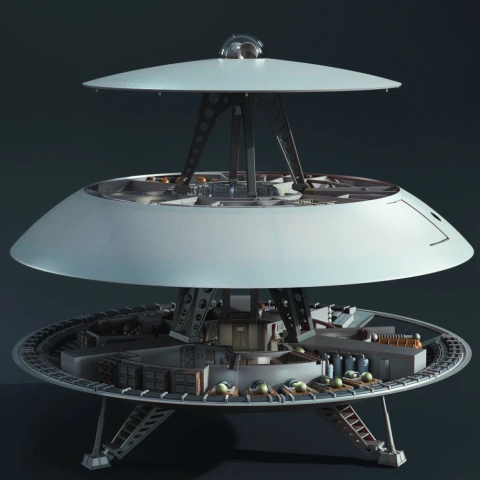
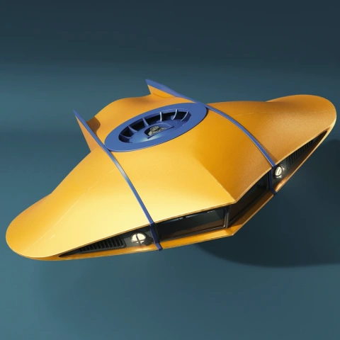
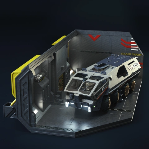
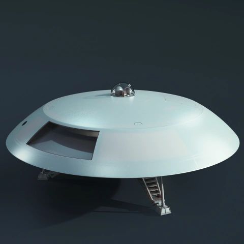
- Scaled-down version of the Off-World Chariot model designed specifically to dock inside the landing bay of the Jupiter 2 3D model (sold separately).
- This compact version has fewer assembly parts, but retains the core exterior details and iconic silhouette.
- The assembly parts are connected using specially designed integrated connectors that fit securely into the corresponding slots. Optionally, for added strength and rigidity, the static connections can be glued together.
FFF/FDM
Assembly method
Connectors, Glue
Features
- Features two track options: static and flexible TPU-ready tracks.
- Choice between active spring-loaded suspension (using standard pen springs) or solid static suspension (part "_82_V1_suspension_c_L_X5_FDM").
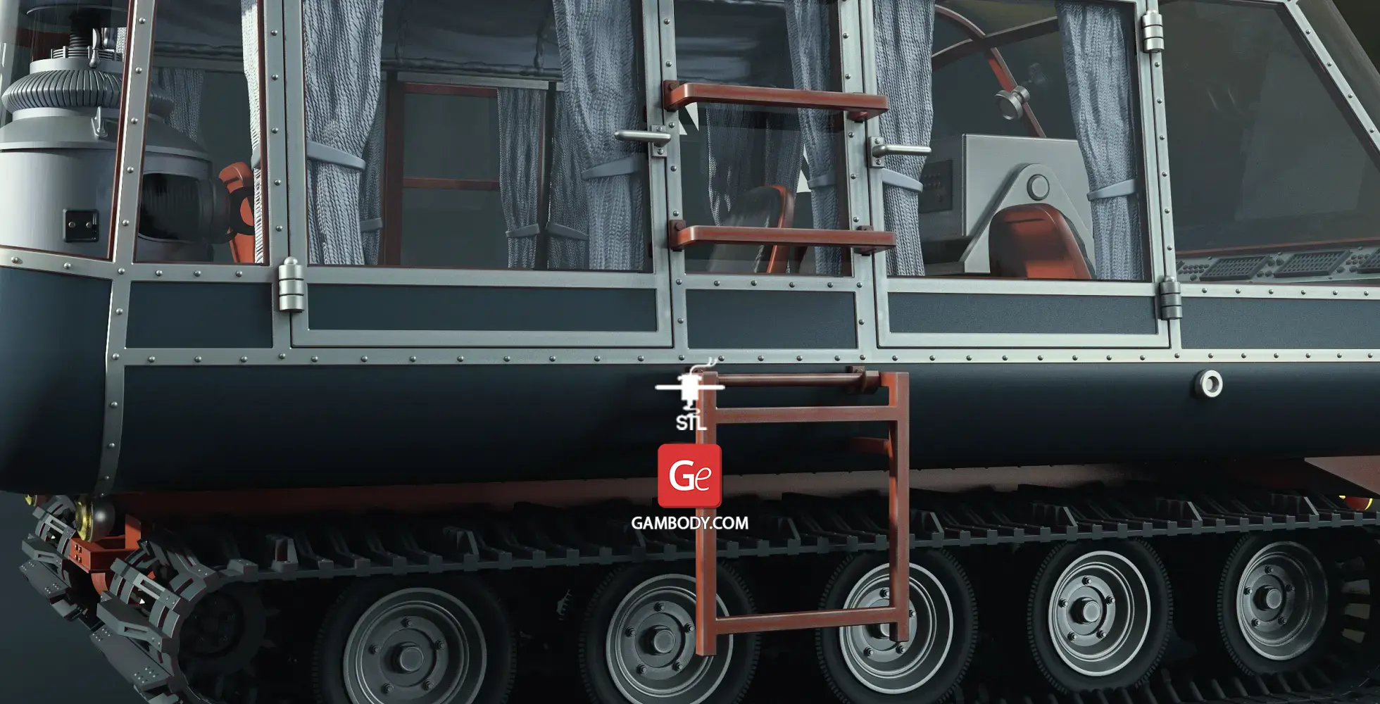
- Multi-option window assembly: print in clear filament, cut manually using provided templates and securing frames, or shape using included vacuum-forming molds.
- Articulated elements include opening side and rear doors, rotating bogie wheels, and a rotatable roof antenna.
- Detailed cabin interior with options for 3D printed curtains or custom fabric.
- Prepared internal channels for optional LED wiring across the headlights, dashboard, and roof laser, powered via a bottom battery compartment with a removable hatch.
- Includes a display platform allowing the vehicle to be mounted flat or at a dynamic inclined angle.
- The assembly parts are connected using specially designed integrated connectors that fit securely into the corresponding slots. Optionally, for added strength and rigidity, the static connections can be glued together.
DLP/SLA
Eco parts
Assembly method
Connectors, Glue
Features
- Features two track options: static treads and tracks ready for flexible resin.
- Multi-option window assembly with printable clear glass templates, frame parts for sheet plastic, and vacuum-forming molds.
- Articulated features including rotatable bogie wheels, rotatable antenna, and opening side and rear cabin doors.
- Detailed interior cabin with options for printed or real fabric curtains.
- Prepared with internal channels for optional LED lighting in the laser, instrument panel, and front headlights, with a bottom battery housing and removable hatch.
- Includes display platform with level and angled mounting positions.
- The assembly parts are connected using specially designed integrated connectors that fit securely into the corresponding slots. Optionally, for added strength and rigidity, the static connections can be glued together.
Additional details
Part of diorama
Yes
Other model in diorama
Add-on pack available
No
You will get instant access to the STL files of Off-World Chariot ATV 3D Printer Files | Assembly + Action after completing your purchase. Simply add the model to your cart and check out using PayPal, credit or debit card, Apple Pay, Google Pay, Alipay, or other available payment methods.
Watch the assembly video for Off-World Chariot ATV 3D Printer Files | Assembly + Action, and explore more tutorials, behind-the-scenes content, 3D printing timelapses, and painting guides on the official Gambody YouTube channel.
This 3D model comes with StereoLithography (.STL) files optimized for 3D printing. You'll get digital files, not a physical product
Before printing, take a look at Printing Details for recommended settings and tips to achieve better results.
Off-World Chariot ATV 3D Printer Files | Assembly + Action includes 2 version(s) for the supported 3D printer type(s): FFF/FDM, DLP/SLA. Files are available for download after purchase.
See the Description and Specifications sections for more details about this model.
| File name | Size (mm | in) | Size(mb) | Printing Time / Filament | |||
|---|---|---|---|---|---|---|
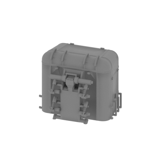
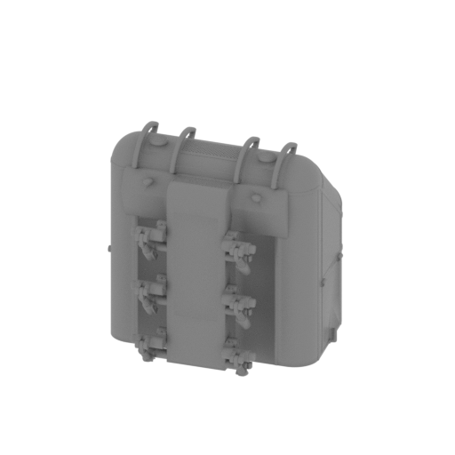 | _01_chariotMiniModel_a_FDM (repaired).stl 34.4 x 34.5 x 34.5 mm | 1.35 x 1.36 x 1.36 in | Size: 34.4 x 34.5 x 34.5 mm | 1.35 x 1.36 x 1.36 in | File size: 86.74 mb | Printing Time / Filament: 39 min / 3 m Slicer: prusa v2.9.2 Printer: prusa_xl Non default settings Layer height: 0.2 Fill density: 20% Support material: 1 Support material buildplate only: 1 | ||
 | _02_chariotMiniModel_b_FDM (repaired).stl 36.4 x 31.6 x 31.1 mm | 1.43 x 1.24 x 1.22 in | Size: 36.4 x 31.6 x 31.1 mm | 1.43 x 1.24 x 1.22 in | File size: 65.59 mb | Printing Time / Filament: 37 min / 3 m Slicer: prusa v2.9.2 Printer: prusa_xl Non default settings Layer height: 0.2 Fill density: 20% Support material: 1 Support material buildplate only: 1 | ||
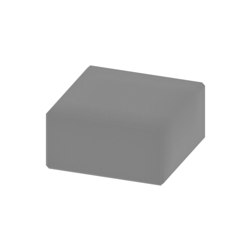 | _03_chariotMiniModel_c_FDM (repaired).stl 16.6 x 16.6 x 8.3 mm | 0.65 x 0.65 x 0.33 in | Size: 16.6 x 16.6 x 8.3 mm | 0.65 x 0.65 x 0.33 in | File size: 0.01 mb | Printing Time / Filament: 8 min / <1 m Slicer: prusa v2.9.2 Printer: prusa_xl Non default settings Layer height: 0.2 Fill density: 20% Support material: 1 Support material buildplate only: 1 | ||
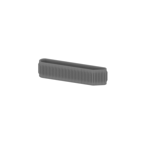 | _04_chariotMiniModel_d_FDM (repaired).stl 49.5 x 8.8 x 11.6 mm | 1.95 x 0.35 x 0.46 in | Size: 49.5 x 8.8 x 11.6 mm | 1.95 x 0.35 x 0.46 in | File size: 35.33 mb | Printing Time / Filament: 18 min / 1 m Slicer: prusa v2.9.2 Printer: prusa_xl Non default settings Layer height: 0.2 Fill density: 20% Support material: 1 Support material buildplate only: 1 | ||
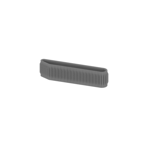 | _05_chariotMiniModel_e_FDM (repaired).stl 49.5 x 8.8 x 11.6 mm | 1.95 x 0.35 x 0.46 in | Size: 49.5 x 8.8 x 11.6 mm | 1.95 x 0.35 x 0.46 in | File size: 35.33 mb | Printing Time / Filament: 18 min / 1 m Slicer: prusa v2.9.2 Printer: prusa_xl Non default settings Layer height: 0.2 Fill density: 20% Support material: 1 Support material buildplate only: 1 | ||
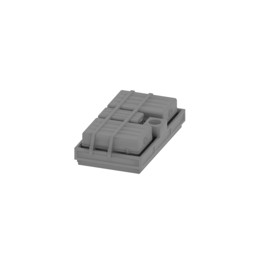 | _06_chariotMiniModel_f_FDM (repaired).stl 12.4 x 22.5 x 6 mm | 0.49 x 0.89 x 0.24 in | Size: 12.4 x 22.5 x 6 mm | 0.49 x 0.89 x 0.24 in | File size: 5.09 mb | Printing Time / Filament: 7 min / <1 m Slicer: prusa v2.9.2 Printer: prusa_xl Non default settings Layer height: 0.2 Fill density: 20% Support material: 1 Support material buildplate only: 1 | ||
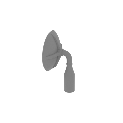 | _07_chariotMiniModel_g_FDM (repaired).stl 5 x 7.6 x 11.2 mm | 0.2 x 0.3 x 0.44 in | Size: 5 x 7.6 x 11.2 mm | 0.2 x 0.3 x 0.44 in | File size: 4.71 mb | Printing Time / Filament: 2 min / <1 m Slicer: prusa v2.9.2 Printer: prusa_xl Non default settings Layer height: 0.2 Fill density: 20% Support material: 1 Support material buildplate only: 1 | ||
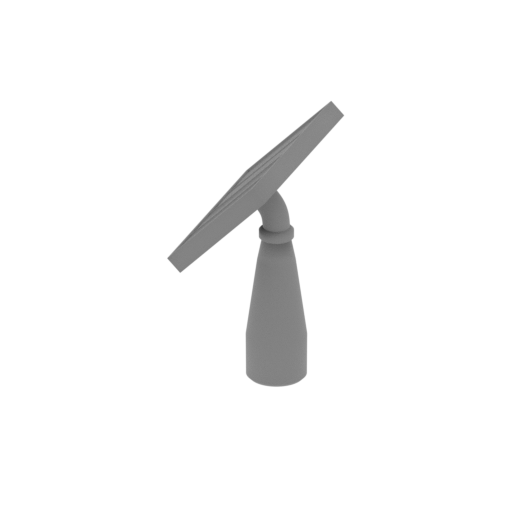 | _08_chariotMiniModel_h_FDM (repaired).stl 3.3 x 7.1 x 8 mm | 0.13 x 0.28 x 0.31 in | Size: 3.3 x 7.1 x 8 mm | 0.13 x 0.28 x 0.31 in | File size: 1.33 mb | Printing Time / Filament: 1 min / <1 m Slicer: prusa v2.9.2 Printer: prusa_xl Non default settings Layer height: 0.2 Fill density: 20% Support material: 1 Support material buildplate only: 1 | ||
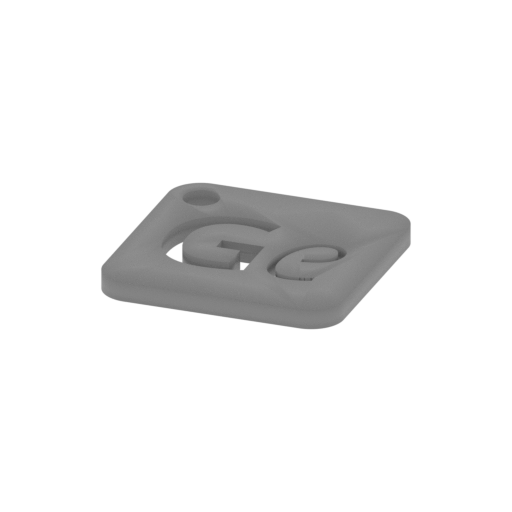 | Keychain (repaired).stl 29.7 x 29.7 x 2.4 mm | 1.17 x 1.17 x 0.09 in | Size: 29.7 x 29.7 x 2.4 mm | 1.17 x 1.17 x 0.09 in | File size: 0.37 mb | Printing Time / Filament: 6 min / 1 m Slicer: prusa v2.9.2 Printer: prusa_xl Non default settings Layer height: 0.2 Fill density: 20% Support material: 1 Support material buildplate only: 1 | ||
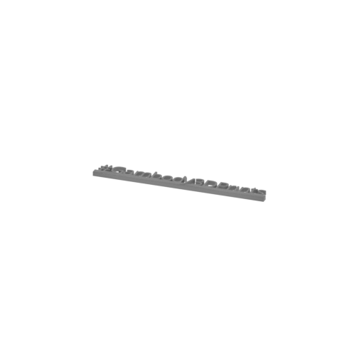 | Tag (repaired).stl 150.1 x 18.2 x 4.6 mm | 5.91 x 0.72 x 0.18 in | Size: 150.1 x 18.2 x 4.6 mm | 5.91 x 0.72 x 0.18 in | File size: 1.78 mb | Printing Time / Filament: 18 min / 2 m Slicer: prusa v2.9.2 Printer: prusa_xl Non default settings Layer height: 0.2 Fill density: 20% Support material: 1 Support material buildplate only: 1 | ||
3D model history
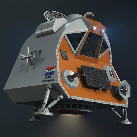
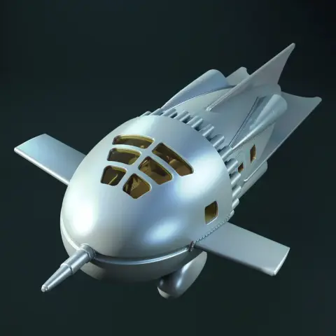
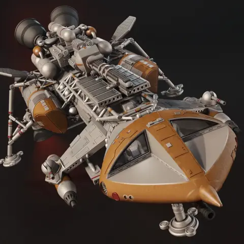
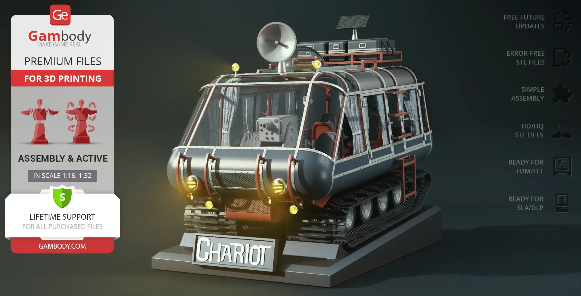
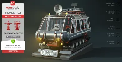
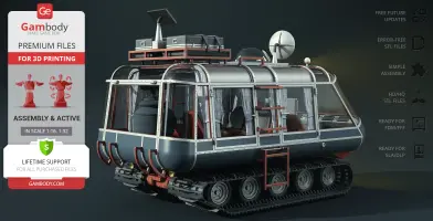
In the original 1965 Lost in Space, exploring an uncharted alien world meant stepping out of the ship and climbing into something far more unusual than a standard rover. The Off-World Chariot was the Robinson family's tracked, amphibious exploration vehicle, built to navigate rugged landscapes, alien bogs, and water crossings. With its transparent bubble cabin, heavy treads, roof-mounted equipment, and compact industrial frame, it carried a distinct retro-futuristic charm. Standing alongside the Robot B9 model and the Space Pod 3D print, the Chariot became a vital part of everyday planetary survival whenever the crew ventured beyond the landing site.
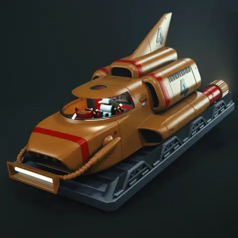
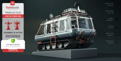
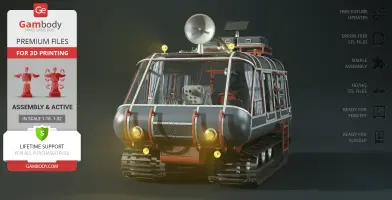
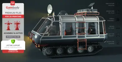
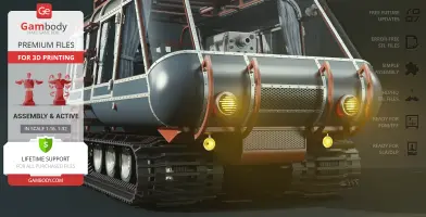
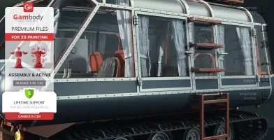
This Off-World Chariot model captures that classic exploration vehicle with an emphasis on functional details. The model includes static treads and tracks ready for flexible materials, rotating bogie wheels, opening doors, and optional spring-loaded active suspension using standard pen springs (FFF/FDM only). Cabin windows can be printed in transparent material, cut from sheet plastic using the included templates, or shaped with the provided vacuum-forming molds. Internal channels support optional LED lighting for the headlights, dashboard, and laser, while a rotatable antenna and detailed interior round out the assembly. A separate version can also fit inside the Jupiter 2 3D model bay (sold separately). This vehicle 3D print is an ideal project for fans building out their Lost in Space 3D print collection or looking for a standalone retro sci-fi 3D print.
3D printing model features
Model-specific features:
- Features two track options: standard static tracks and flexible tracks designed for TPU filament or flexible resin.
- Features functional bogie wheels designed to rotate.
- Supports optional active, spring-loaded suspension utilizing standard automatic ballpoint pen springs (FFF/FDM only).
- Roof-mounted antenna mast can be manually rotated.
- Includes printable window templates and frame parts for cutting clear sheet plastic, alongside dedicated molds for vacuum forming.
- Offers detailed cabin interior features, opening side doors, opening rear door, and a choice between printed or real fabric curtains.
- Equipped with built-in internal channels supporting optional LED lighting for the laser, dashboard instrument panel, and front headlights.
- Battery compartment is positioned conveniently at the bottom of the chassis and secured with a removable hatch cover.
- Can be showcased flat on its tracks or mounted at a dynamic angle on the provided display platform.
- Includes a scaled-down version designed to dock inside the Jupiter 2 3D printing model bay (sold separately).
Printing & assembly details:
- Provided as error-free STL files compatible with most 3D printers;
- Optimized part division minimizes support material and ensures smooth and precise surface detailing;
- The assembly parts in the FFF/FDM version come in the recommended print orientations for easy bed placement;
- Assembly manual in PDF and video formats is included for the FFF/FDM and DLP/SLA versions;
- The model is available in recommended scales — 1:32 for the FFF/FDM version and 1:64 for the DLP/SLA versions.
What will you get after purchase?
- 3 versions of Off-World ChariotSTL files for FFF/FDM, FFF/FDM Mini to pair with Jupiter 2 3D print model (sold separately), and DLP/SLA — files for all versions are available for download after the purchase;
- STL files of high-poly Off-World Chariot model for 3D printing consist of 255 files;
- Sizes for:
- FFF/FDM Model Size: 180 mm wide, 212 mm high, 318 mm deep;
- FFF/FDM Platform Size: 176 mm wide, 62 mm high, 296 mm deep;
- FFF/FDM Mini Model Size: 36 mm wide, 44 mm high, 66 mm deep;
- DLP/SLA Model Size: 90 mm wide, 106 mm high, 158 mm deep;
- DLP/SLA Platform Size: 88 mm wide, 31 mm high, 148 mm deep;
- Assembly Manual for 1.0 FFF/FDM and 1.0 DLP/SLA versions in PDF and video formats;
- Detailed settings that we provide as a recommendation for Bambu Studio, Cura, Orca Slicer, PrusaSlicer, Simplify3D, and Slic3r for the best print;
- Full technical support from the Gambody Support Team.
Average customer rating (1 reviews)
5
Ratings breakdown
Click a star rating to filter reviews
Overall experience
Level of detail in the model
5
Model cut quality and assembly guide
4.9
Clarity and accuracy of the model page
4.6


 Verified purchase
 Level of detail in the model
5
Model cut quality and assembly guide
4.9
Clarity and accuracy of the model page
4.6


 Community Support Team
 The model includes both the main version and a scaled-down Mini version designed to fit inside the Jupiter 2 3D printing model. The Mini version consists of 8 parts.
The Initial version is the more detailed standalone option and is available in two print adaptations: 139 parts for FFF/FDM at 1:16 scale and 108 parts for DLP/SLA at 1:32 scale.
We’re very glad the initial version made such a positive impression, and we appreciate you taking the time to share your experience with other makers.
Below you'll find detailed slicing settings for Bambu Studio 2.0+, Orca Slicer 2.0+, UltiMaker Cura 5.0+, PrusaSlicer 2.0+, Slic3r 1.3+, Simplify3D 5.0+ to help you get the best results when printing this model. These settings are optimized specifically for this 3D model, but please note they may need slight adjustments depending on your printer or filament. When in doubt, refer to your printer's user manual.
To avoid printing issues and achieve the best quality, we highly recommend applying the following settings:
 Bambu Studio 2.0+
 For better quality use 0.12 mm layer height, for fast printing use 0.2 mm layer height. For pins and the Ge connectors, use 0.2 layer height.
120-150% of your Layer Height
But you can paint the seam if you want.
You have to calibrate this parameter
You have to calibrate this parameter
You have to calibrate this parameter
For pins and power elements of the structure, such as the vehicle frame, use 3 loop
Disabled for vehicles and enabled for characters
For 0,2 Layer Height
The parameters in this tab vary greatly, it all depends on the quality of your printer. For example, if you have a classic Ender3, stick to the minimum parameters, but if you have a newer printer, for example Anycubic cobra 3 v2, you can select the maximum recommended values
Settings for advanced users, change these parameters only if you have sufficient 3D printing expertise
Enable this parameter if your model requires supports
We also recommend placing and removing supports manually in some places using special button
1-2 loops for more thick support
Top Z distance = 1-1.3 layer Height. If the supports are hard to remove, try increasing this setting by 0.1-0,4 mm
Bottom Z distance = 1-1.3 layer Height. If the supports are hard to remove, try increasing this setting by 0.1-0,4 mm
You have to calibrate this parameter which one is better for your filament
Increase this parameter if the supports are hard to remove from walls
For PLA and PETG filament types
5-8 mm is optional for small prints that have bad adhesion to the build plate
You have to calibrate this parameter
Read the description on your filament roll
Read the description on your filament roll and increase this parameter for fast printers
Read the description on your filament roll and increase this parameter for fast printers
 Orca Slicer 2.0+
 For better quality use 0.12 mm layer height, for fast printing use 0.2 mm layer height. For pins and the Ge connectors, use 0.2 layer height.
120-150% of your Layer Height
But you can paint the seam if you want.
0.01-0.05 You have to calibrate this parameter
0.01-0.05 You have to calibrate this parameter
0.1-0.2 You have to calibrate this parameter
For pins and power elements of the structure, such as the vehicle frame, use 3 loop
Disabled for vehicles and ships, enabled for characters
For 0,2 Layer Height
For 0,2 Layer Height
The parameters in this tab vary greatly, it all depends on the quality of your printer. For example, if you have a classic Ender3, stick to the minimum parameters, but if you have a newer printer, for example, Anycubic Kobra 3 Or Bambulab A1, you can select the maximum recommended values.
Settings for advanced users, change these parameters only if you have sufficient 3D printing expertise
Enable this parameter if your model requires supports
We also recommend placing and removing supports manually in some places using special button
Top Z distance = 1-1.3 layer Height. If the supports are hard to remove, try increasing this setting by 0.1-0,4 mm
Bottom Z distance = 1-1.3 layer Height. If the supports are hard to remove, try increasing this setting by 0.1-0,4 mm
Increase this parameter if the supports are hard to remove from walls
For PLA and PETG filament types
5-8 mm is optional for small prints that have bad adhesion to the build plate
Read the description on your filament roll
Read the description on your filament roll and increase this parameter for fast printers
You have to calibrate this parameter
Read the description on your filament roll and increase this parameter for fast printers
Read the description on your filament roll
This field is filled in according to your printer specifications when you add it to the slicer.
You can add custom G-code here for the start and end of the print. However, be careful - this is for advanced users only!
You have to calibrate your printer using Ge retraction test models
Retraction Length: For direct-drive setups use 0.5 mm to 2.5 mm; for Bowden extruders use 5 to 7 mm
This is how fast the filament is pulled back—40-60 mm/s for direct drive and 30-50 mm/s for Bowden setups.
You have to calibrate this parameter: Reduce it until the printer starts to hit the parts with the nozzle during printing, then increase it by 0.2.
 UltiMaker Cura 5.0+
 For better quality use 0.12 mm layer height, for fast printing use 0.2 mm layer height. For pins and the Ge connectors, use 0.2 layer height.
120-150% of your Layer Height
To increase the strength of the print parts, use wall line count: 3
For pins and connectors use 50% Infill
These parameters are for standard PLA plastic. If you are using a different type of plastic, check the printing temperature recommended by the manufacturer. Also, read the description on your filament spool. For fast printers, add +30 °C to the current parameters.
The parameters in this tab vary greatly, it all depends on the quality of your printer. For example, if you have a classic Ender3, stick to the minimum parameters, but if you have a newer printer, for example Anycubic cobra 3 v3, you can select the maximum recommended values
Settings for advanced users, change these parameters only if you have sufficient 3D printing expertise.
You need to calibrate this parameter using Gambody test models. These values are average values for a Direct Drive extruder; for a Bowden extruder, the values should be increased.
You need to calibrate this parameter using Gambody test models. These values are average values for a Direct Drive extruder; for a Bowden extruder, the values should be increased.
Use this value other than 0 if your nozzle catches on the internal infill during travel moves. Try to keep this value as low as possible in height.
Use normal supports to support large, straight surfaces (most mechanical or technical parts).
You have to calibrate this parameter according to the capabilities of your printer and your filament, using a Gambody test models.
Use 1 instead of 0 if your supports are thin and tall. They will be harder to remove, but much stronger.
Top Z distance = 1-1.3 layer Height. If the supports are hard to remove, try increasing this setting by 0.1-0,4 mm
Increase this parameter if the supports are hard to remove from walls
Use tree supports to support complex objects, such as characters.
You have to calibrate this parameter according to the capabilities of your printer and your filament, using a Gambody test models.
Top Z distance = 1-1.3 layer Height. If the supports are hard to remove, try increasing this setting by 0.1-0,4 mm
Increase this parameter if the supports are hard to remove from walls
Use a skirt for all parts when printing on outdated printers.
Use a brim when printing thin but tall parts, as well as parts with a small bed adhesion area.
 PrusaSlicer 2.0+
 For better quality use 0.12 mm layer height, for fast printing use 0.2 mm layer height. For pins and the Ge connectors, use 0.2 layer height.
120-150% of your Layer Height
for 0.2 Layer Height
But you can paint the seam if you want.
(for PLA and PETG)
(5-8 mm is optional for small prints that have bad adhesion to the build plate)
Enable this parameter if your model requires supports
(45-50 degree)You have to calibrate this parameter according to the capabilities of your printer
and your filament, using a Gambody test models.
Top contact Z distance = 1-1.3 layer Height. If the supports are hard to remove, try
increasing this setting by 0.1-0,4 mm
Top contact Z distance = 1-1.3 layer Height. If the supports are hard to remove, try
increasing this setting by 0.1-0,4 mm
Increase this parameter if the supports are hard to remove from walls
The parameters in this tab vary greatly, it all depends on the quality of your printer. For example, if you have a classic Ender3, stick to the minimum parameters, but if you have a newer printer, for example Anycubic cobra 3 v3, you can select the maximum recommended values
Settings for advanced users, change these parameters only if you have sufficient 3D printing expertise. Use the minimum value for outdated printers without acceleration calibration, and the maximum value for modern printers if you need it.
These settings only work for 3D printers with multiple extruders
You can try setting all parameters in this section, except the First layer, to values between 0.75% of your nozzle diameter and 1.25% of your nozzle diameter. Adjusting them will help you work out the optimal parameters for the best quality for your print. As for the First layer, you can set it to 150% of the diameter of your nozzle for better adhesion to the build plate (for a nozzle with a diameter of 0.4 mm, the First layer extrusion width can be from 0.3 mm to 0.5 mm)
For better printing quality you have to calibrate this parameter using Gambody test model.
Check your filament manufacturer's temperature recommendations on the spool.
Cooling parameters depends on the material you use for printing.
*for PLA
 Slic3r 1.3+
 For better quality use 0.12 mm layer height, for fast printing use 0.2 mm layer height. For pins and the Ge connectors, use 0.2 layer height.
120-150% of your Layer Height
For 0.12 Layer Height
For 0.12 Layer Height
For pins and connectors use 50% Infill
Use skirt for outdated 3d printers
(5-8 mm is optional for small prints that have bad adhesion to the build plate)
Enable this parameter if your model requires supports
(45-60 degree)You have to calibrate this parameter according to the capabilities of your printer and your filament, using a Gambody test models
Contact Z distance = 1-1.3 layer Height. If the supports are hard to remove, try increasing this setting by 0.1-0,4 mm
The parameters in this tab vary greatly, it all depends on the quality of your printer. For example, if you have a classic Ender3, stick to the minimum parameters, but if you have a newer printer, for example Anycubic cobra 3 v3, you can select the maximum recommended values
Settings for advanced users, change these parameters only if you have sufficient 3D printing expertise. Use the minimum value for outdated printers without acceleration calibration, and the maximum value for modern printers if you need it.
You have to calibrate this parameter from 0.9 to 1.1 according to the capabilities of your printer and your filament, using a Gambody test models.
Check your filament manufacturer's temperature recommendations on the spool.
Cooling parameters depends on the material you use for printing.
Calibrate this value if you need to reduce or improve the adhesion between the plastic and the heat bed
Your current nozzle diameter
You need to calibrate this parameter using Gambody test models. These values are average values for a Direct Drive extruder; for a Bowden extruder, the values should be increased.
 Simplify3D 5.0+
 Your current nozzle diameter
You have to calibrate this parameter using Gambody test models.
You need to calibrate this parameter using Gambody test models. These values are average values for a Direct Drive extruder; for a Bowden extruder, the values should be increased.
For better quality use 0.12 mm layer height, for fast printing use 0.2 mm layer height. For pins and the Ge connectors, use 0.2 layer height.
For 0,2 Layer Height
For 0,2 Layer Height
To increase the strength of the print parts, use Outline Perimeters: 3
You can enable this parameter to print rounded or spherical models, as well as character models.
Use this option only if your parts are too tight. but better calibrate your printer extrusion
Use this option only if your parts are too tight. but better calibrate your printer extrusion
Use 2 and more if you want to create skirt instead brim
1-2 for skirt and 10-20 for brim
Use for wipe nozzle if you need
Use For ABS filament
For pins and connectors use 50% Infill
Top Z distance = 1-1.3 layer Height. If the supports are hard to remove, try increasing this setting by 0.1-0,4 mm
Calibrate your filament and detect optimal temperature for it
Average temperature for PLA filament
The parameters in this tab vary greatly, it all depends on the quality of your printer. For example, if you have a classic Ender3, stick to the minimum parameters, but if you have a newer printer, for example Anycubic cobra 3 v3, you can select the maximum recommended values
Settings for advanced users, change these parameters only if you have sufficient 3D printing expertise.
FFF/FDM
- Scaled-down version of the Off-World Chariot model designed specifically to dock inside the landing bay of the Jupiter 2 3D model (sold separately).
- This compact version has fewer assembly parts, but retains the core exterior details and iconic silhouette.
- The assembly parts are connected using specially designed integrated connectors that fit securely into the corresponding slots. Optionally, for added strength and rigidity, the static connections can be glued together.
DLP/SLA
- Features two track options: static treads and tracks ready for flexible resin.
- Multi-option window assembly with printable clear glass templates, frame parts for sheet plastic, and vacuum-forming molds.
- Articulated features including rotatable bogie wheels, rotatable antenna, and opening side and rear cabin doors.
- Detailed interior cabin with options for printed or real fabric curtains.
- Prepared with internal channels for optional LED lighting in the laser, instrument panel, and front headlights, with a bottom battery housing and removable hatch.
- Includes display platform with level and angled mounting positions.
- The assembly parts are connected using specially designed integrated connectors that fit securely into the corresponding slots. Optionally, for added strength and rigidity, the static connections can be glued together.
FFF/FDM
- Features two track options: static and flexible TPU-ready tracks.
- Choice between active spring-loaded suspension (using standard pen springs) or solid static suspension (part "_82_V1_suspension_c_L_X5_FDM").
- Multi-option window assembly: print in clear filament, cut manually using provided templates and securing frames, or shape using included vacuum-forming molds.
- Articulated elements include opening side and rear doors, rotating bogie wheels, and a rotatable roof antenna.
- Detailed cabin interior with options for 3D printed curtains or custom fabric.
- Prepared internal channels for optional LED wiring across the headlights, dashboard, and roof laser, powered via a bottom battery compartment with a removable hatch.
- Includes a display platform allowing the vehicle to be mounted flat or at a dynamic inclined angle.
- The assembly parts are connected using specially designed integrated connectors that fit securely into the corresponding slots. Optionally, for added strength and rigidity, the static connections can be glued together.