


Files
3D model format
Stereolithography (.stl)
Total files
Slicer settings
not available
Mesh error check
not specified
Support
Lifetime support from Gambody team
Update requests
not specified
Model versions
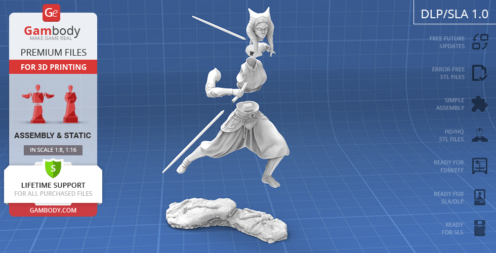
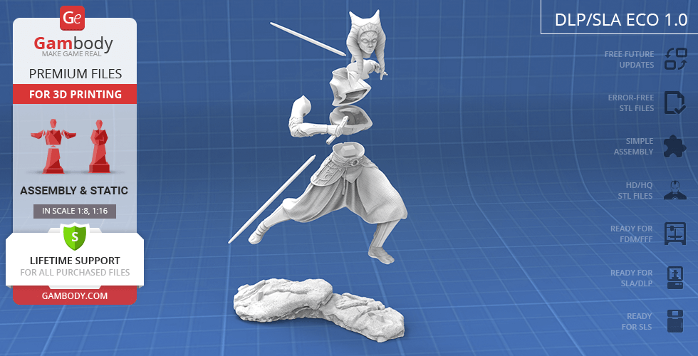
DLP/SLA
Eco parts
Assembly method
Connectors
Features
STL files are pre-supported, hollowed out, and have drain holes where needed;
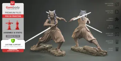
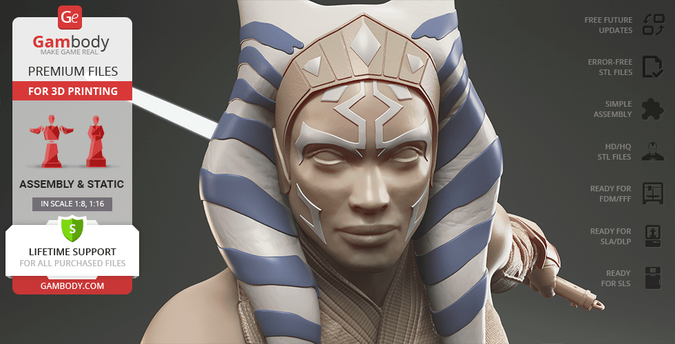
Alternative head version: smooth surface without raised ornaments on face and hair;
The assembly parts are connected using specially designed integrated connectors that fit securely into the corresponding slots. Optionally, for added strength and rigidity, the static connections can be glued together;
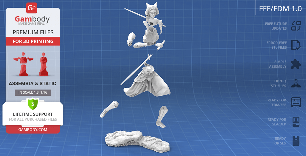
FFF/FDM
Assembly method
Connectors
Features
Alternative head version: smooth surface without raised ornaments on face and hair;
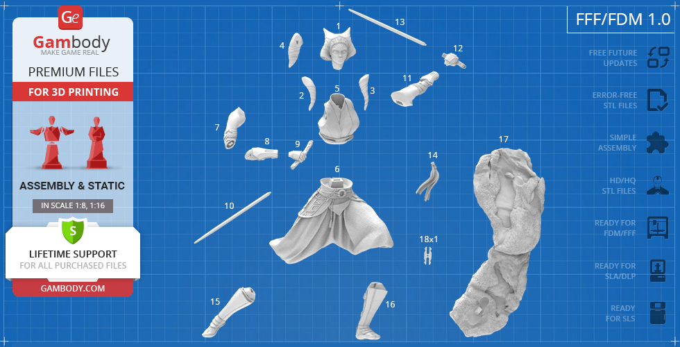
The assembly parts are connected using specially designed integrated connectors that fit securely into the corresponding slots. Some model parts use separate connectors (part "18_ge_lock_7S(x1)_)FDM", requires 1 copy);
DLP/SLA
Eco parts
Assembly method
Connectors
Features
Alternative head version: smooth surface without raised ornaments on face and hair;
The assembly parts are connected using specially designed integrated connectors that fit securely into the corresponding slots. Optionally, for added strength and rigidity, the static connections can be glued together;
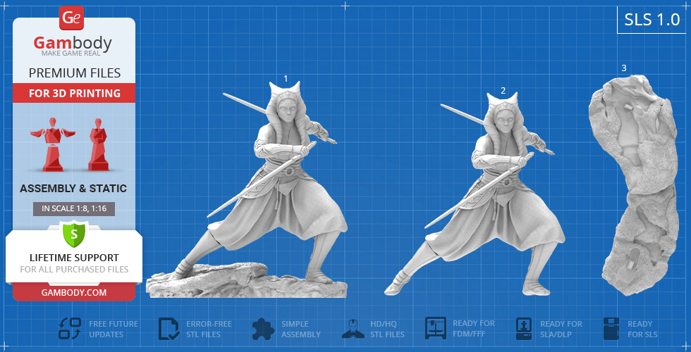
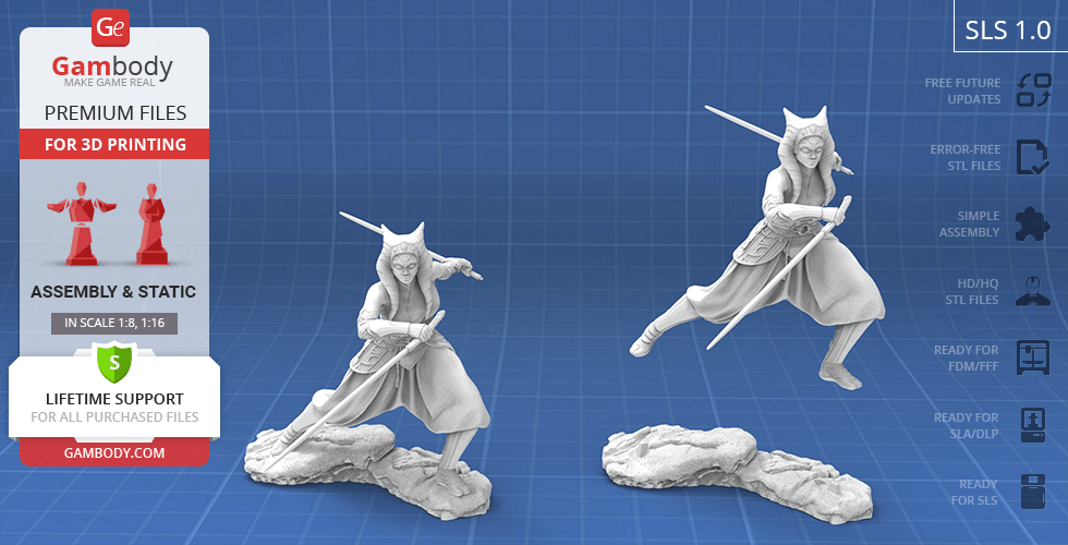
SLS
Assembly method
Connectors
Features
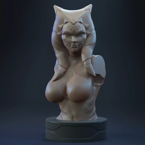
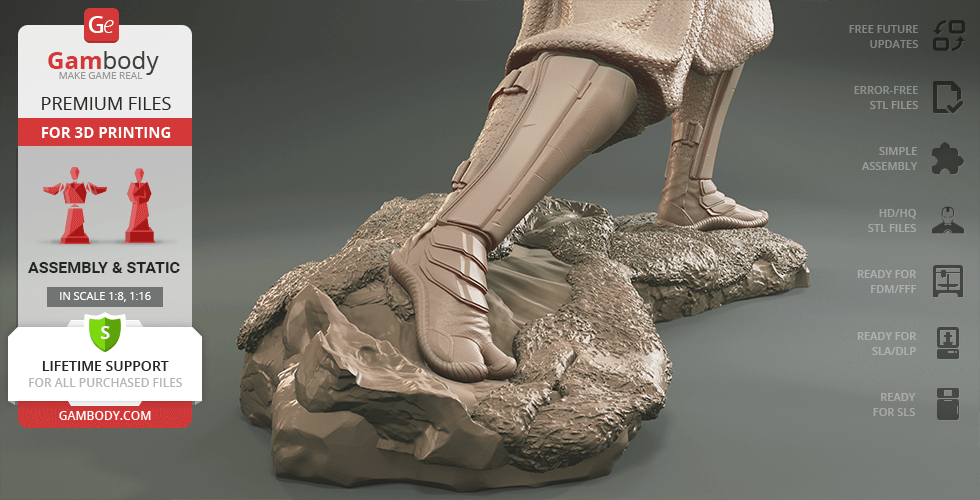
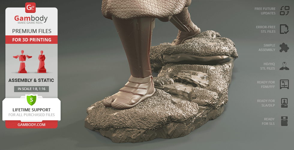
Contains 3 parts: a solid Ahsoka Tano model with and without the platform;
The assembly parts are connected using specially designed integrated connectors that fit securely into the corresponding slots. Optionally, for added strength and rigidity, the static connections can be glued together;
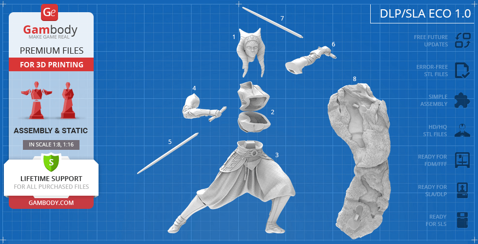
DLP/SLA
Eco parts
Assembly method
Connectors
Features
Contains some hollowed out parts to save resin;
Alternative head version: smooth surface without raised ornaments on face and hair;
The assembly parts are connected using specially designed integrated connectors that fit securely into the corresponding slots. Optionally, for added strength and rigidity, the static connections can be glued together;
Additional details
Part of diorama
No
Special pack included
No
You can get the STL files of Ahsoka Tano for 3D printing immediately after the purchase! Just click the green Buy button in the top-right corner of the model’s page. You can pay with PayPal or your credit card.
Watch the tutorial on how to assemble the 3D printed Ahsoka Tano from the provided 3D print files on Gambody YouTube channel.
Also, you may like TV Series 3D Print Models, as well as Movies STL files.
________
FAQ:
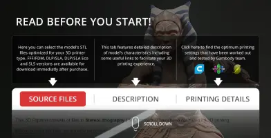
This 3D model comes with StereoLithography (.STL) files optimized for 3D printing. You'll get digital files, not a physical product
Before printing, take a look at Printing Details for recommended settings and tips to achieve better results.
Ahsoka Tano 3D Printing Model | Assembly includes 3 version(s) for the supported 3D printer type(s): FFF/FDM, DLP/SLA, SLS. Files are available for download after purchase.
See the Description and Specifications sections for more details about this model.
3D model history
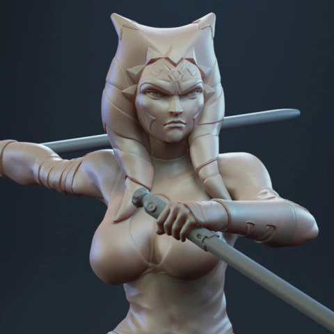
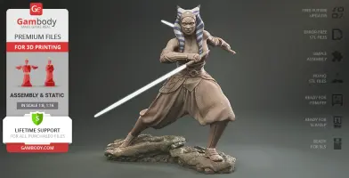
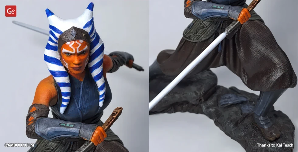
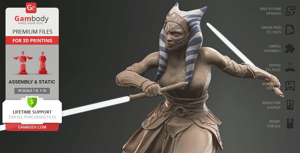
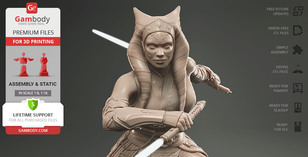
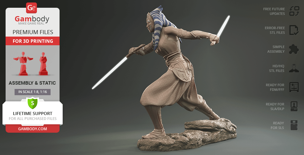
Among the vast universe of Star Wars, Ahsoka Tano appears as of the fan-favourite heroines. The complex and enigmatic Force-sensitive Togruta has gone through transformations that shaped her battle-hardened yet boundlessly protective character. When chasing her own ideals and understanding of the world, she found herself not affiliated with the Jedi or Sith. And that is when our contributing 3D artist found her the most fascinating!
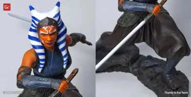
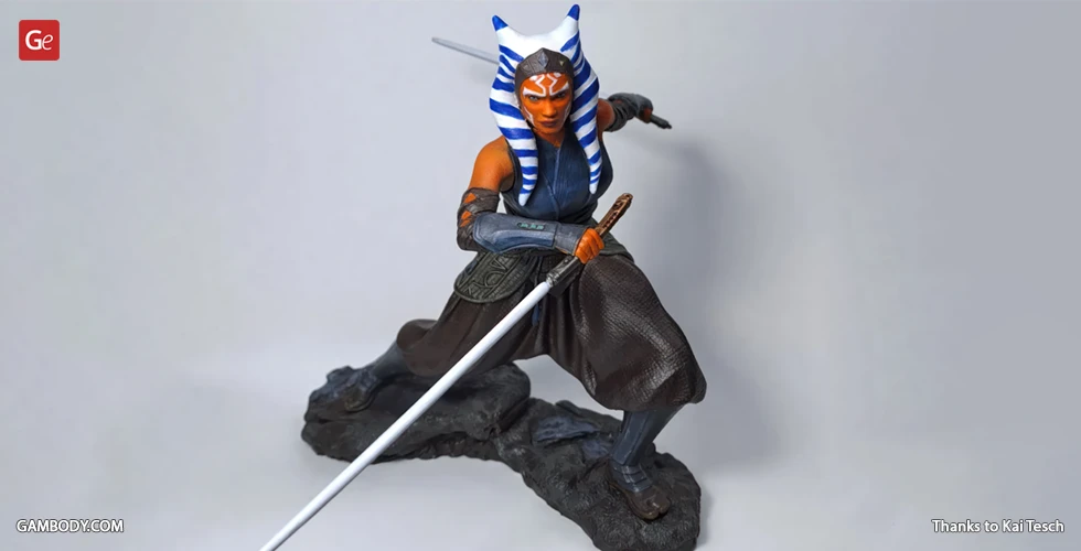
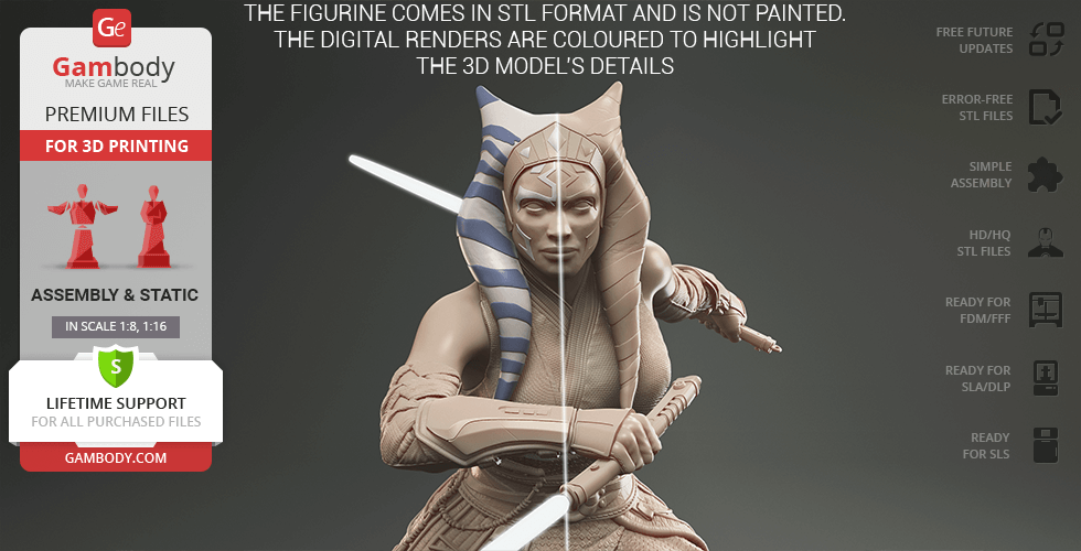
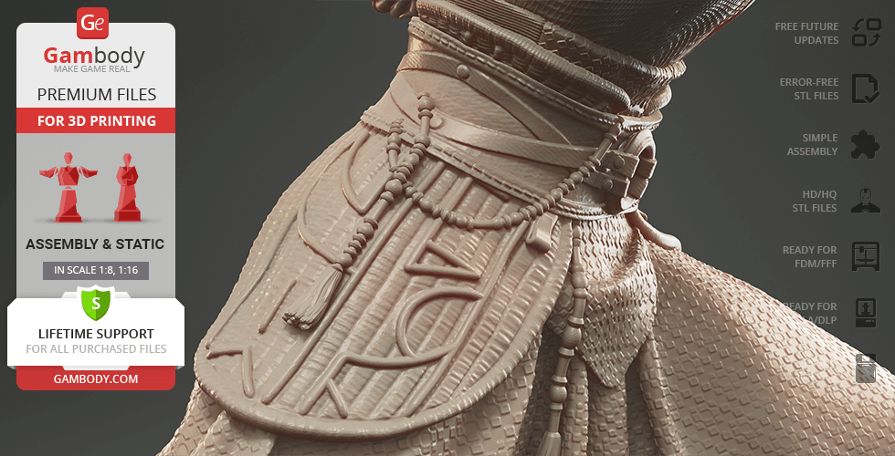
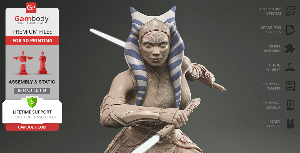
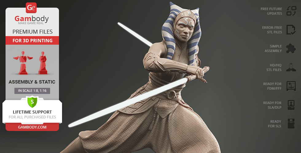
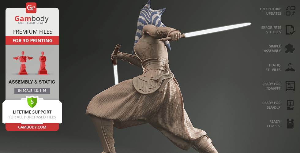
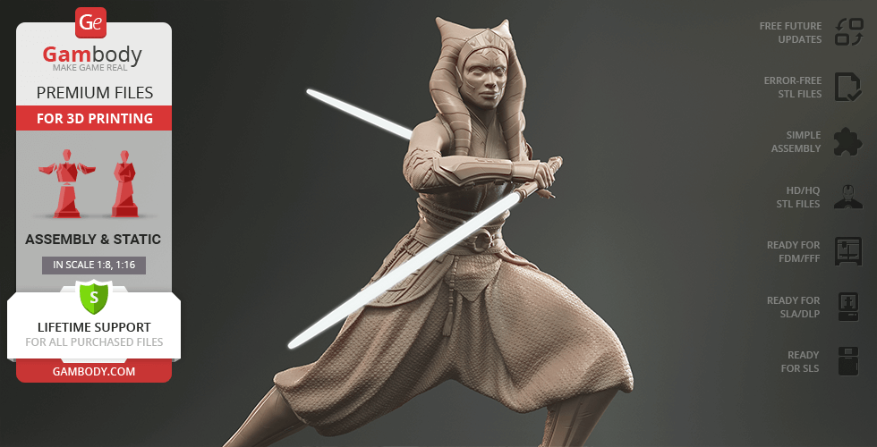
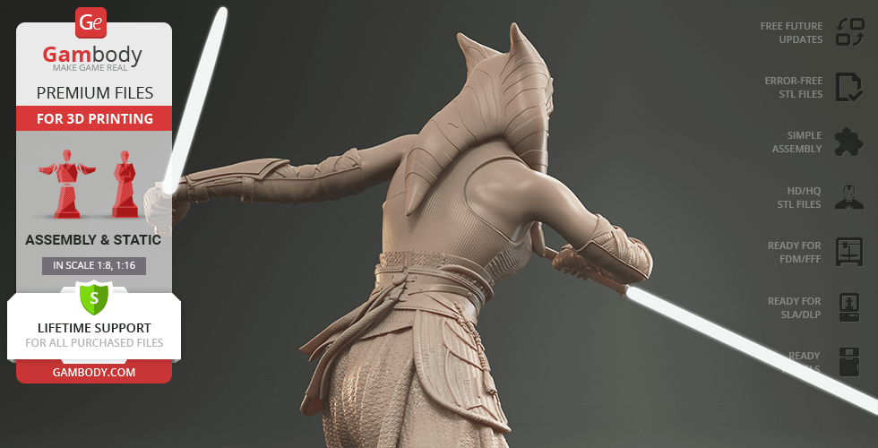
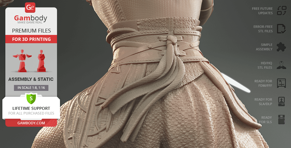
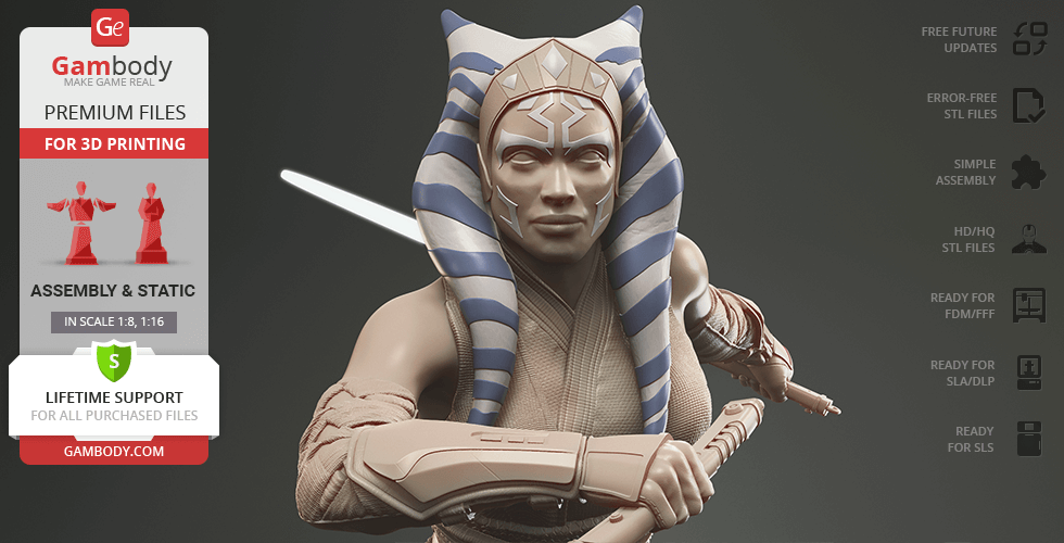
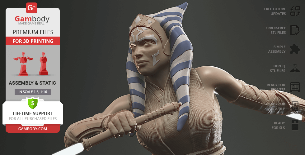
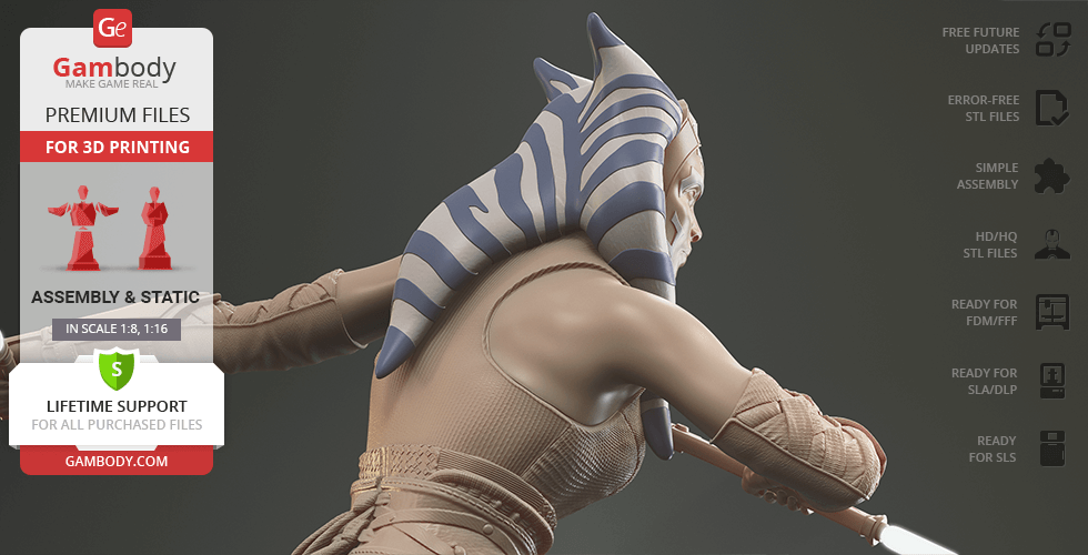
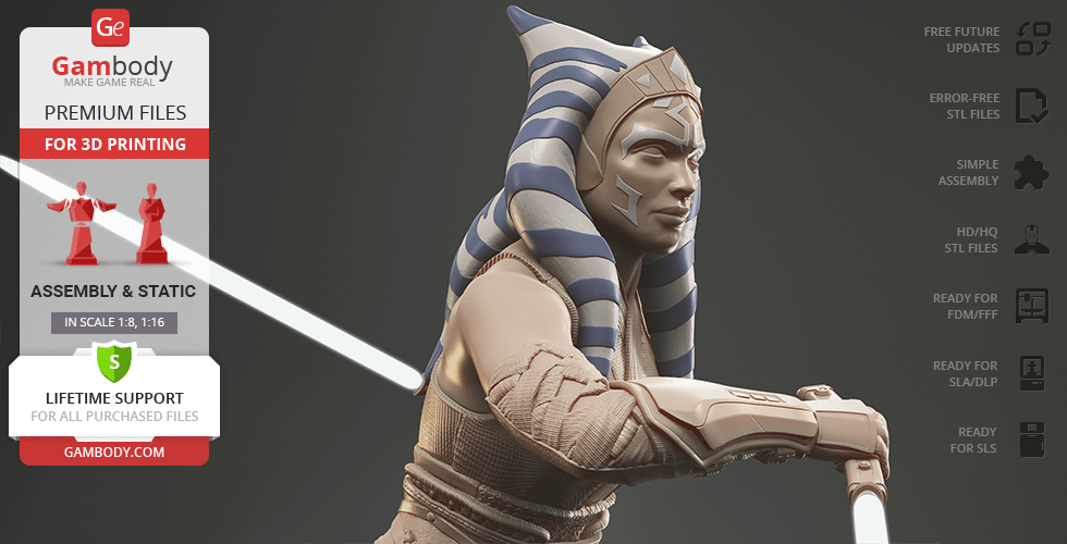
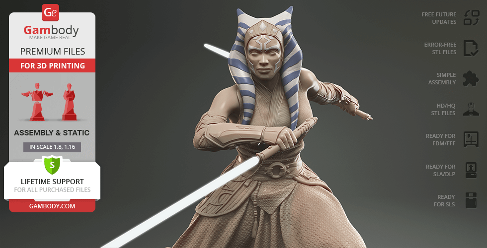
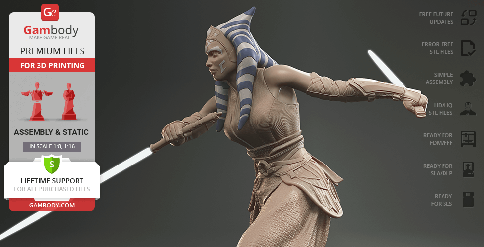
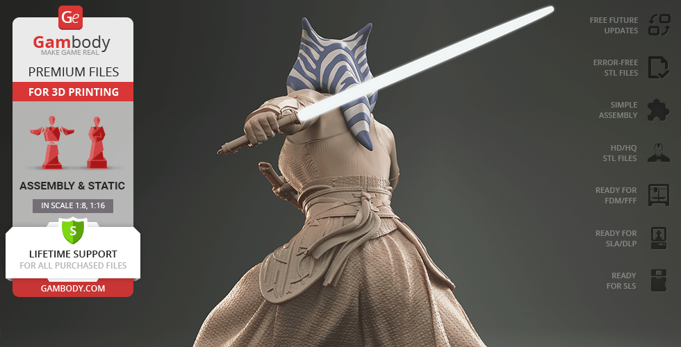
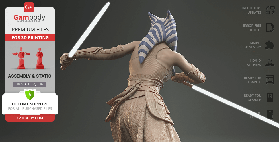
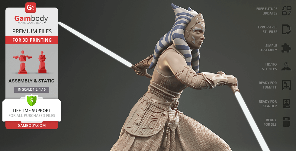
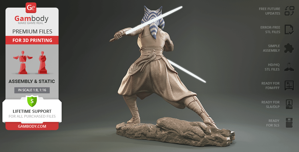
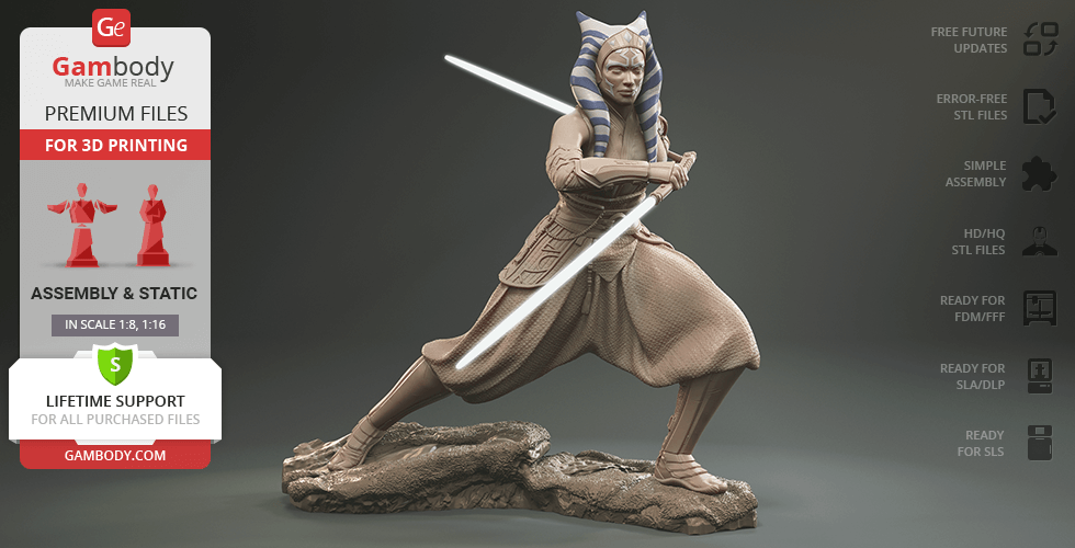
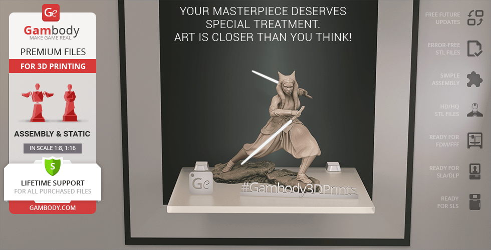
Somewhere between the storylines of The Mandalorian and The Book of Boba Fett, Ahsoka engaged in combat. She froze in with her white-bladed lightsabers at ready, the symbols of her self-standing nature. The highly detailed model bears a stunning resemblance to the Togruta, with her unique lekku and montrals patterns on display. The clothing is no less impressive - carefully sculpted accessories, folds on her loose pants and protective armour pieces look like real-life pieces.
Will you join her side?
3D printing model features
Model-specific features:
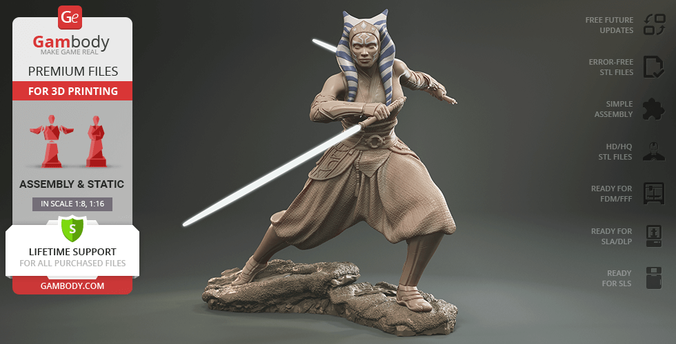
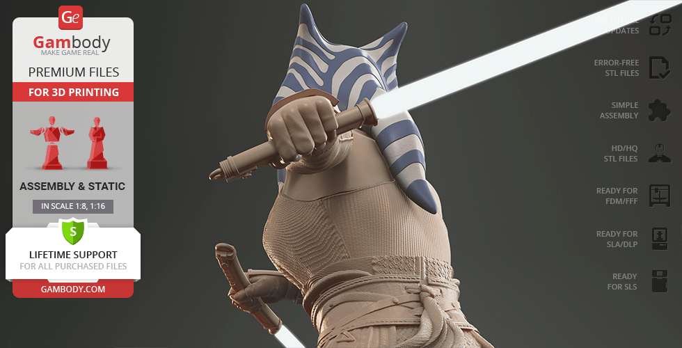
- Inspired by the classic Star Wars universe, this Ahsoka Tano 3D print model is captured in a dynamic battle pose with her signature lightsabers;
- The model bears a stunning resemblence to the Torguta, with her unique lekku and montrals patterns on display;
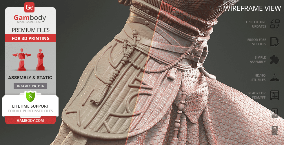
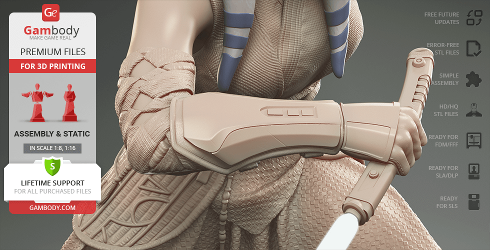
- The clothing is highly detailed, featuring carefully sculpted accessories, folds on her loose pants, and protective armor pieces;
- The model comes with an alternative head version without raised ornaments on the face and hair.
Printing & assembly details:
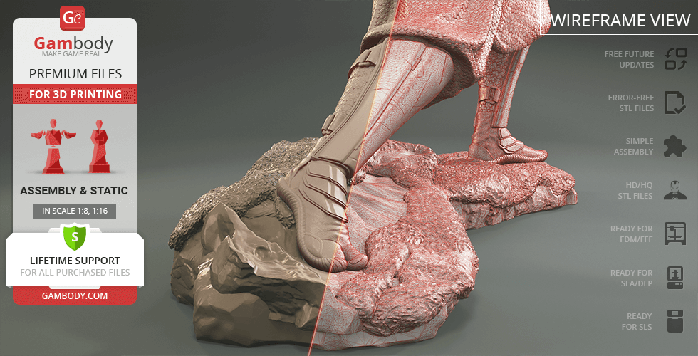
- Provided as error-free STL files compatible with most 3D printers;
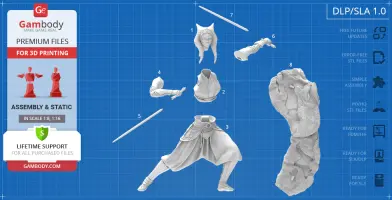
- Optimized part division minimizes support material and ensures smooth surface detail;
- The assembly parts in the FFF/FDM version come in the recommended print orientations for easy bed placement;
- Assembly manual in PDF and video formats is included for both FFF/FDM and DLP/SLA versions;
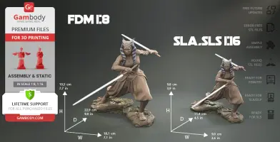
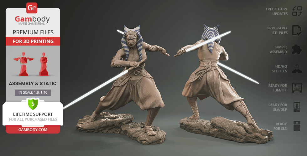
- The model is available in recommended scales of 1:8 for the FFF/FDM version and 1:16 for the DLP/SLA/SLS versions, based on the 1.76-meter height of Ahsoka Tano.
What will you get after purchase?
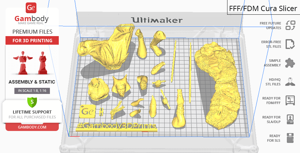
- 5 versions of Ahsoka Tano STL files for FFF/FDM, DLP/SLA, DLP/SLA Eco, DLP/SLA Pre-supported and SLS - files for each version are available for download after the purchase;
- STL files of high-poly Ahsoka Tano 3D printer model consist of 51 parts;
- Sizes:
- FFF/FDM: 181 mm wide, 195 mm high, 229 mm deep;
- DLP/SLA/SLS: 98 mm wide, 90 mm high, 114 mm deep;
- Assembly Manual for FFF/FDM 1.0 and DLP/SLA 1.0 versions in PDF format;
- Detailed settings that we provide as a recommendation for Bambu Studio, Cura, Orca Slicer, PrusaSlicer, Simplify3D, and Slic3r for the best print;
- Full technical support from the Gambody Support Team.
Average customer rating (7 reviews)
4.6
Ratings breakdown
Click a star rating to filter reviews
Overall experience
Level of detail in the model
4.6
Model cut quality and assembly guide
4.6
Clarity and accuracy of the model page
4.6
Level of detail in the model
5
Model cut quality and assembly guide
5
Clarity and accuracy of the model page
5
Level of detail in the model
4
Model cut quality and assembly guide
4
Clarity and accuracy of the model page
4
Level of detail in the model
5
Model cut quality and assembly guide
5
Clarity and accuracy of the model page
5
Level of detail in the model
5
Model cut quality and assembly guide
5
Clarity and accuracy of the model page
5
Level of detail in the model
5
Model cut quality and assembly guide
5
Clarity and accuracy of the model page
5
Level of detail in the model
3
Model cut quality and assembly guide
3
Clarity and accuracy of the model page
3
Level of detail in the model
5
Model cut quality and assembly guide
5
Clarity and accuracy of the model page
5
To avoid printing issues and achieve the best quality, we highly recommend applying the following settings:
Generic
Below you can find printing recommendations for Bambu Studio, Cura, Orca Slicer, PrusaSlicer, Simplify3D, and Slic3r software.
Disclaimer: The following printing settings are a recommendation, not an obligation. The parameters can vary depending on the peculiarities of your 3D printer, the material you use, and especially the particular assembly part you are working with. Each part that any model comprises often needs preliminary review, and you are free to tweak the settings the way you find suitable.
Note:
You can scale up the model (downscaling for FFF/FDM 3D printers is not recommended!);
All connectors should be printed at 100% Infill.
Bambu Lab printing recommendations:
These basic 3D printing settings recommendations for beginners were tested in Bambu Studio 1.9.1. Test models were printed on the Bambu Lab A1, Bambu Lab A1 Mini, Creality Ender 3 S1, Anycubic Kobra 2, and Anycubic Vyper using PLA and PETG filaments.
To avoid printing problems, we recommend the following settings:download
Cura printing recommendations:
These are averaged settings which were tested in the Cura 5.2.1 slicer. Test models were printed on Anycubic Vyper, Creality Ender 3 Pro with PLA filament.
To avoid printing problems, we recommend the following settings: download
Orca Slicer printing recommendations:
These basic 3D printing settings recommendations for beginners were tested in Orca Slicer 2.3.0. Test models were printed on Bambu Lab A1, Bambu Lab A1 Mini, Creality Ender 3 V3, and Anycubic Kobra 3 with PLA and PETG filament.
To avoid printing problems, we recommend the following settings: download
PrusaSlicer printing recommendations:
These basic 3D printing settings recommendations for beginners were tested in PrusaSlicer 2.3.1. Test models were printed on Ultimaker 2, Creality Ender 3, Creality Cr-10S pro v2, Anycubic I3 Mega, Anycubic I3 MegaS, Anycubic Vyper with PLA and PETG filaments.
To avoid printing problems, we recommend the following settings:download
Simplify3D printing recommendations:
These are averaged settings which were tested in the Simplify3D 5.0.0 slicer. Test models were printed on Anycubic Vyper, FLSUN v400, Ender3 S1 with PLA filament.
To avoid printing problems, we recommend the following settings:download
Slic3r printing recommendations:
These basic 3D printing settings recommendations for beginners were tested in Slic3r 1.3.0 software. Test models were printed on Ultimaker 2, Creality Ender 3, Creality Cr-10S pro v2, Anycubic I3 Mega, Anycubic I3 MegaS, Anycubic Vyper with PLA and PetG filaments.
To avoid printing problems, we recommend the following settings:download
DLP/SLA
STL files are pre-supported, hollowed out, and have drain holes where needed;
Alternative head version: smooth surface without raised ornaments on face and hair;
The assembly parts are connected using specially designed integrated connectors that fit securely into the corresponding slots. Optionally, for added strength and rigidity, the static connections can be glued together;
SLS
Contains 3 parts: a solid Ahsoka Tano model with and without the platform;
The assembly parts are connected using specially designed integrated connectors that fit securely into the corresponding slots. Optionally, for added strength and rigidity, the static connections can be glued together;
DLP/SLA
Contains some hollowed out parts to save resin;
Alternative head version: smooth surface without raised ornaments on face and hair;
The assembly parts are connected using specially designed integrated connectors that fit securely into the corresponding slots. Optionally, for added strength and rigidity, the static connections can be glued together;
DLP/SLA
Alternative head version: smooth surface without raised ornaments on face and hair;
The assembly parts are connected using specially designed integrated connectors that fit securely into the corresponding slots. Optionally, for added strength and rigidity, the static connections can be glued together;
FFF/FDM
Alternative head version: smooth surface without raised ornaments on face and hair;
The assembly parts are connected using specially designed integrated connectors that fit securely into the corresponding slots. Some model parts use separate connectors (part "18_ge_lock_7S(x1)_)FDM", requires 1 copy);