


This should take overall.

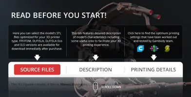
This 3D Model consists of files in StereoLithography (.Stl) format that is optimized for 3D printing.
Before printing the files, we strongly recommend reading the PRINTING DETAILS section.
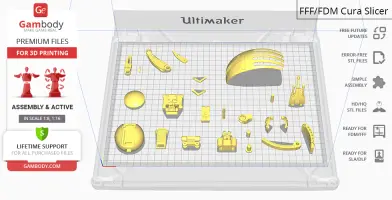
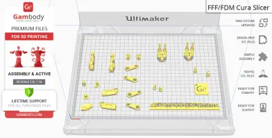
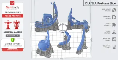
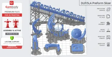
Droideka 3D Printing Model comes in 2 versions for FFF/FDM and DLP/SLA/SLS 3D printers. Files for both versions are available for download after purchase.
Detailed information about this 3D printing model is available in the DESCRIPTION section.

|
|||||
|---|---|---|---|---|---|
| File Name | File Size | Time / Filament | Object Size (x/y/z mm) |
||
|
1_Body_Top_Fdm (repaired) .stl |
11.37 MiB | 3 h 9 min 2 m | 44 x 44 x 34 | Download | |
|
2_Body_Bot_Fdm (repaired) .stl |
2.73 MiB | 54 min 1 m | 33 x 33 x 14 | Download | |
|
3_Body_Detail_Fdm (repair ed).stl |
5.39 MiB | 23 min <1 m | 20 x 36 x 7 | Download | |
|
4_Rear_Mechanism_Fdm (rep aired).stl |
4.91 MiB | 2 h 5 min 1 m | 33 x 40 x 37 | Download | |
|
5_Spine_Detail_Fdm (repai red).stl |
3.00 MiB | 53 min 1 m | 28 x 18 x 22 | Download | |
|
6_Chest_Fdm (repaired).st l |
8.59 MiB | 1 h 25 min 1 m | 29 x 34 x 21 | Download | |
|
7_Сhest_Plug_Fdm (repair ed).stl |
1.38 MiB | 20 min <1 m | 13 x 28 x 6 | Download | |
|
8_Spine_Fdm (repaired).st l |
5.74 MiB | 52 min <1 m | 16 x 45 x 20 | Download | |
|
9_Shild_R_Fdm (repaired). stl |
4.74 MiB | 28 min <1 m | 12 x 18 x 27 | Download | |
|
10_Shild_L_Fdm (repaired) .stl |
4.74 MiB | 26 min <1 m | 12 x 18 x 27 | Download | |
|
11_Neck_Fdm (repaired).st l |
1.45 MiB | 25 min <1 m | 58 x 18 x 8 | Download | |
|
12_Connector_Body_Leg_x3_ Fdm (repaired).stl |
0.94 MiB | 15 min <1 m | 21 x 14 x 10 | Download | |
|
13_Leg_x3_Fdm (repaired). stl |
9.85 MiB | 42 min <1 m | 44 x 43 x 10 | Download | |
|
14_Leg_Plug_x3_Fdm (repai red).stl |
0.09 MiB | 8 min <1 m | 26 x 26 x 5 | Download | |
|
15_Foot_x3_Fdm (repaired) .stl |
15.95 MiB | 18 min <1 m | 12 x 42 x 5 | Download | |
|
16_Foot_Plug_x3_Fdm (repa ired).stl |
0.05 MiB | 1 min <1 m | 3 x 14 x 2 | Download | |
|
17_Connecrot_Foot_Leg_x3_ Fdm (repaired).stl |
1.26 MiB | 9 min <1 m | 10 x 10 x 13 | Download | |
|
18_Connecrot_Rear_Chest_F dm (repaired).stl |
0.73 MiB | 8 min <1 m | 6 x 6 x 13 | Download | |
|
19_Connector_Cyl_Fdm (rep aired).stl |
0.20 MiB | 9 min <1 m | 4 x 4 x 29 | Download | |
|
20_Head_Connector_Fdm (re paired).stl |
0.19 MiB | 8 min <1 m | 5 x 5 x 18 | Download | |
|
21_Head_fdm (repaired).st l |
4.71 MiB | 1 h 27 min 1 m | 26 x 25 x 51 | Download | |
|
22_Body_Detail_2_Fdm (rep aired).stl |
0.55 MiB | 3 min <1 m | 23 x 12 x 3 | Download | |
|
23_Body_Detail_3_Fdm (rep aired).stl |
0.55 MiB | 3 min <1 m | 23 x 12 x 3 | Download | |
|
24_Body_Shild_Fdm (repair ed).stl |
6.14 MiB | 9 h 19 min 7 m | 40 x 92 x 55 | Download | |
|
25_Shield_Arm_R_Fdm (repa ired).stl |
0.65 MiB | 22 min <1 m | 25 x 12 x 16 | Download | |
|
26_Shield_Arm_L_Fdm (repa ired).stl |
0.65 MiB | 21 min <1 m | 25 x 12 x 16 | Download | |
|
27_Connector_Leg_x3_Fdm ( repaired).stl |
1.41 MiB | 9 min <1 m | 11 x 11 x 12 | Download | |
|
28_Arm_L_Fdm (repaired).s tl |
5.33 MiB | 30 min <1 m | 36 x 17 x 10 | Download | |
|
29_Arm_R_Fdm (repaired).s tl |
5.33 MiB | 31 min <1 m | 36 x 17 x 10 | Download | |
|
30_Connector_Hand_L_Fdm ( repaired).stl |
1.25 MiB | 9 min <1 m | 12 x 13 x 13 | Download | |
|
31_Connector_Hand_R_Fdm ( repaired).stl |
1.25 MiB | 9 min <1 m | 12 x 13 x 13 | Download | |
|
32_Connector_Weapon_Hand_ L_Fdm (repaired).stl |
0.16 MiB | 11 min <1 m | 6 x 6 x 15 | Download | |
|
33_Connector_Weapon_Hand_ R_Fdm (repaired).stl |
0.16 MiB | 11 min <1 m | 6 x 6 x 15 | Download | |
|
34_Hand_L_Fdm (repaired). stl |
3.49 MiB | 47 min <1 m | 13 x 45 x 15 | Download | |
|
35_Hand_R_Fdm (repaired). stl |
3.48 MiB | 48 min <1 m | 13 x 45 x 15 | Download | |
|
36_Loop_1_L_Fdm (repaired ).stl |
0.35 MiB | 9 min <1 m | 32 x 18 x 4 | Download | |
|
37_Loop_1_R_Fdm (repaired ).stl |
0.35 MiB | 10 min <1 m | 32 x 18 x 4 | Download | |
|
38_Loop_2_L_Fdm (repaired ).stl |
0.35 MiB | 9 min <1 m | 32 x 18 x 4 | Download | |
|
39_Loop_2_R_Fdm (repaired ).stl |
0.35 MiB | 9 min <1 m | 32 x 18 x 4 | Download | |
|
40_Mechanism_L_Fdm (repai red).stl |
0.26 MiB | 7 min <1 m | 10 x 15 x 6 | Download | |
|
41_Mechanism_R_Fdm (repai red).stl |
0.26 MiB | 6 min <1 m | 10 x 15 x 6 | Download | |
|
42_Piston_A_L_Fdm (repair ed).stl |
2.55 MiB | 15 min <1 m | 8 x 8 x 17 | Download | |
|
43_Piston_A_R_Fdm (repair ed).stl |
2.55 MiB | 16 min <1 m | 8 x 8 x 17 | Download | |
|
44_Piston_B_L_Fdm (repair ed).stl |
2.47 MiB | 11 min <1 m | 8 x 8 x 14 | Download | |
|
45_Piston_B_R_Fdm (repair ed).stl |
2.47 MiB | 11 min <1 m | 8 x 8 x 14 | Download | |
|
46_Weapon_L_Fdm (repaired ).stl |
40.56 MiB | 1 h 36 min 1 m | 24 x 16 x 59 | Download | |
|
47_Weapon_R_Fdm (repaired ).stl |
40.57 MiB | 1 h 34 min 1 m | 24 x 16 x 59 | Download | |
|
Keychain (repaired).stl |
0.35 MiB | 23 min <1 m | 30 x 30 x 2 | Download | |
|
Tag (repaired).stl |
1.70 MiB | 1 h 16 min 1 m | 150 x 18 x 5 | Download | |
| ... | |||||
This should take overall.
ABOUT THIS 3D MODEL
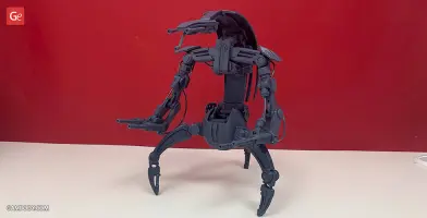
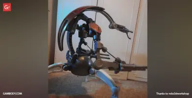
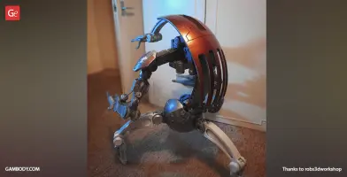
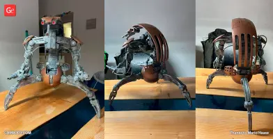
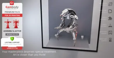
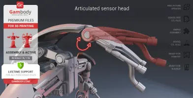
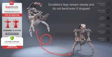
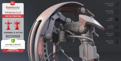
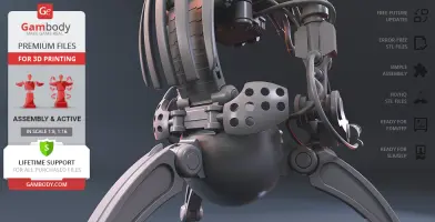
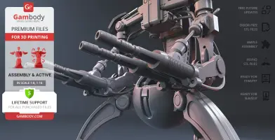
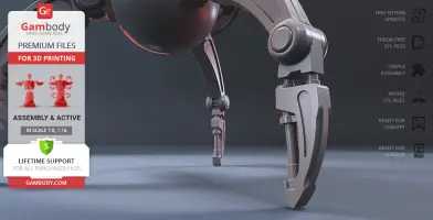
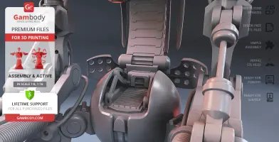
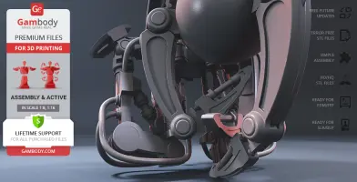
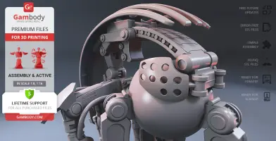
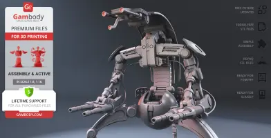
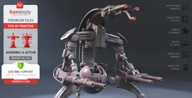
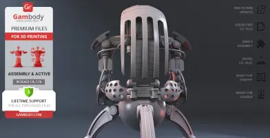
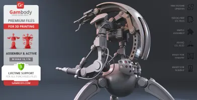
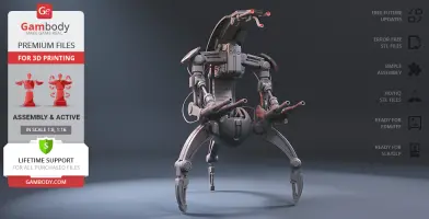
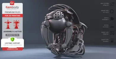
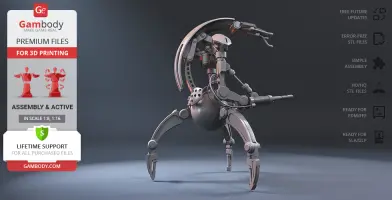
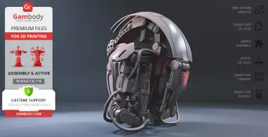
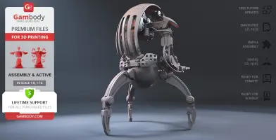
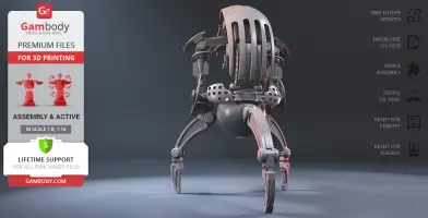
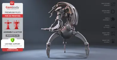
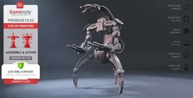
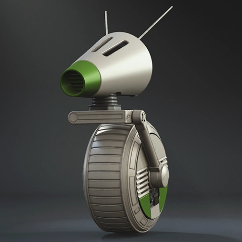
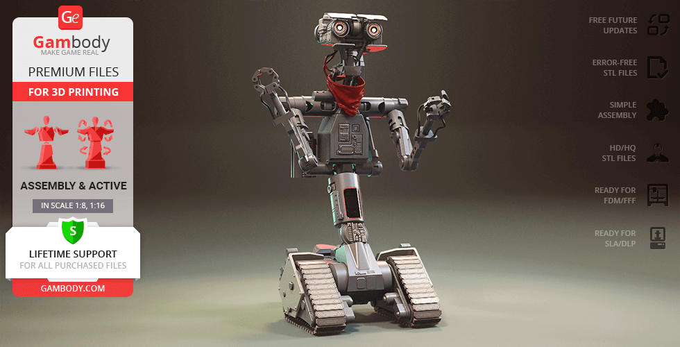
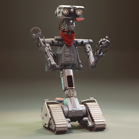
Droidekas are a type of dangerous and deadly droids of the Separatist/CIS army that dramatically roll themselves into a battle and guarantee a merciless attack on the opponents. Unlike Battle Droids that were produced in millions of copies, the Destroyers are far more expensive and extremely effective thanks to their impressive defensive and offensive armament. While standing on its three sharp legs the Droideka can simultaneously utilise its personal deflector shield generator and fire at a target using two twin repeating blaster cannons! After that, the Droideka can swiftly curl into a ball and travel to the next target at a surprisingly rapid pace. The manner of Destroyers’ transformation and transit earned droids the “Rollies” nickname and the reputation of formidable and murderous enemies to stand against. The author of the fantastic Droideka model for 3D printing reportedly dedicated circa 150 hours for the iconic Destroyer to roll into the 3D printed collections of Star Wars fans. Similarly to its on-screen counterpart, the 3D printing Destroyer Droid is heavily armed, carrying twin high-energy blasters on each of its arms. The slim sensor head is equipped with a pair of non-visual composite radiation sensor antennas and a single primary sensor antenna that vaguely resemble the robot’s eyes and nose. The round Droideka’s backshell plate looks perfectly ready to furl into a compact wheel in a matter of seconds making the Destroyer a smaller and speedier target for the opponents. The 3D artist also made sure to equip the droid with the deflector shield projector plates, making the Droideka almost invincible to be defeated by an unprepared brave spirit. Boasting the one-of-a-kind silhouette, the Droideka 3D printing model will become a unique piece of Colicoids’ technology on your display shelf!
ADAPTATION FOR 3D PRINTING
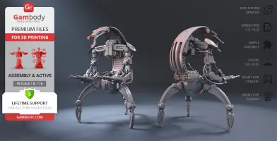
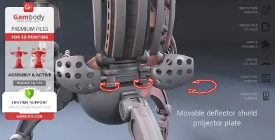
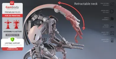
Droideka model for 3D printing is a highly articulated action assembly model and its moderation and adaptation for different types of 3D printers took Gambody team 48 hours in total. In order to ensure the transformation and multidirectional movement of the Destroyer, it was divided into many assembly parts and special mechanisms were introduced into all model’s joints to give you an opportunity to display the droid in a variety of positions, i.e. its backshell plate, sternum plate, censor head, spinal power cell series, twin high-energy blasters, shield plates, legs, foot claws, etc. come as separate assembly parts. The pistons (arm extensor struts) on Droideka’s arms and the neck are retractable. For you to introduce hydraulic cables that connect the Droideka’s parts in the model’s FFF/FDM 1.0 version we recommend that you use the 1.75mm PLA filament and insert its pieces into designated holes that are designed to fit securely the diameter. The assembly of some of Droideka’s parts (like deflector shield projector plate) requires additional “pins”. These pins do not come in STL files as well but can be made out of short pieces of regular 1.75 PLA. All assembly parts are provided in STL files in recommended positions that were worked out in order to ensure the smoothness of the details’ surfaces after printing and so that the 3D printing beginners won't face difficulties when placing the parts on a build plate. The joints that ensure the droid’s movability and transformation are provided as separate files as well for you to be able to print them again if the joints' friction happens to lose rigidity. The cutting in the droid's FFF/FDM and DLP/SLA/SLS versions was made taking into account the peculiarities of each 3D printing technology. We highly recommend that you watch "Assembly video" in the photo preview section before assembling the Droideka. When downloading any model's file you will also receive "Assembly Manual" for FFF/FDM 1.0 and DLP/SLA/SLS 1.0 versions in PDF format.
The model is saved in STL files, a format supported by most 3D printers. All STL files for 3D printing have been checked in Netfabb and no errors were shown.
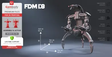
The model's scale was calculated from Droideka's actual height that is 1750 mm. The 3D printing model's chosen scale is 1:8 for the FFF/FDM version and 1:16 for the DLP/SLA/SLS version.
VERSION SPECIFICATIONS
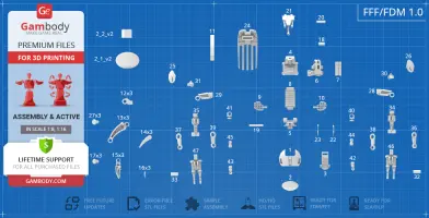
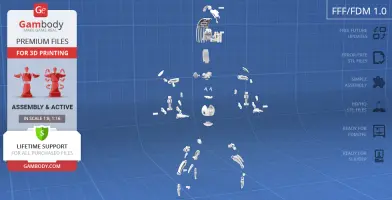
FFF/FDM 1.0 version features:
- Contains 47 parts;
- A printed model is 228 mm tall, 156 mm wide, 192 mm deep;
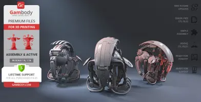
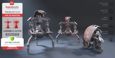
- Droideka can be transformed into a ball;
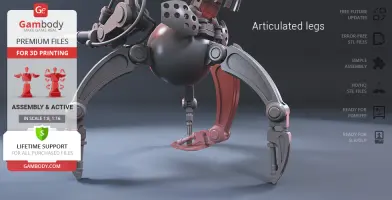
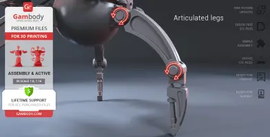
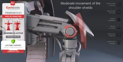
- Each droid's joint (head, neck, "pelvis", sternum, shoulder, elbow, wrist, hip, knee, and shields) is articulated which allows the model's multidirectional movement and transformation;
- This version's assembly requires additional “pins” to secure the parts. These pins do not come in STL files but can be made out of short pieces of regular 1.75 PLA;
- Hydraulic cables that connect the Droideka's parts are not provided with STL files. You can use 1.75mm filament of your choice and insert its pieces into designated holes;
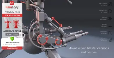
- The pistons on the Droideka's arms are retractable, i.e. they move when you bend the model's articulated arms;
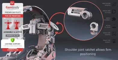
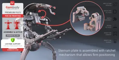
- For the highly articulated Droideka to stand firmly in any position you may choose there was a ratchet mechanism introduced in the model’s shoulder, sternum, and hip joints;
- It is highly recommended that you watch "Assembly video" in the photo preview section and read "Assembly Manual" in PDF before assembling the Droideka;
- All parts are divided in such a way that you will print them with the smallest number of support structures.
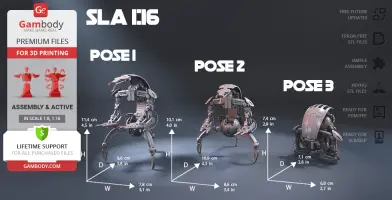
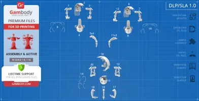
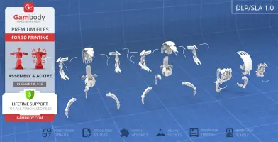
DLP/SLA/SLS 1.0 version features:
- Contains 20 parts;
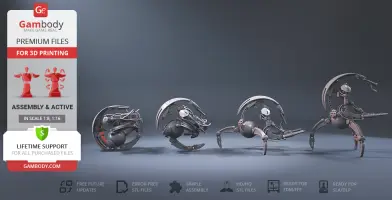
- A printed model in combat stance (P1) is 114 mm tall, 78 mm wide, 96 mm deep;
- intermediate position (P2) is 101 mm tall, 86 mm wide, 109 mm deep;
- wheel form (P3) is 74 mm tall, 68 mm wide, 71 mm deep;
- Comprises parts for you to assemble Droideka in any of three static poses - combat stance, intermediate position, wheel form;
- All parts are divided in such a way to fit the build plates and to ensure that support structures are generated where needed.
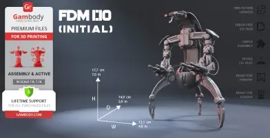
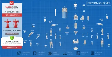
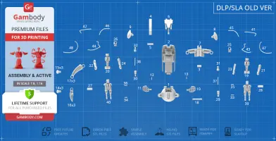
FFF/FDM (Old version), DLP/SLA/SLS (Old version):
- Comes in 1:10 scale;
- Contain 47 and 48 parts respectively;
- When printed both versions stand 177 mm tall, 121 mm wide, 149 mm deep;
- The initial versions of the Droideka model that were uploaded in an incorrect scale;
- These versions' features correspond with the ones of the FFF/FDM 1.0 version.
WHAT WILL YOU GET AFTER PURCHASE?
- STL files of Droideka Model for 3D printing which consist of 67 parts;
- 2 versions of files for this model for FFF/FDM and DLP/SLA/SLS;
- High-poly detailed model of Droideka;
- Assembly Manual for FFF/FDM 1.0 and DLP/SLA/SLS 1.0 versions in PDF format;
- Detailed settings that we provide as a recommendation for Cura , Simplify3D and Slic3r for the best print;
- Full technical support from the Gambody Support Team.
You can get the model of Droideka for 3D Printing immediately after the purchase! Just click the green Buy button in the top-right corner of the model’s page. You can pay with PayPal or your credit card.
Watch the tutorial on how to assemble Droideka 3D Printing Model at Gambody YouTube channel.
Also, you may like other Space War Online 3D Printing Figurines as well as other Droid 3D Printing Models.
_______
FAQ:
Where can I print a model if I have no printer?
How to get started with 3D printing?
How to set up my 3D printer?
How to choose right 3D model print bed positioning?
How to paint printed figurine?
This model was tested in Cura 3.4.1 and printed on an Ultimaker 2 in PLA material. Below you can find printing recommendations for Cura, Simplify3D and Slic3r softwares.
To avoid printing problems, we recommend the following settings:
Quality
Layer Height: 0.1 mm
Initial Layer Height: 0.3 mm
Line Width: 0.4 mm
Wall Line Width: 0.4 mm
Outer Wall Line Width: 0.4 mm
Inner Wall(s) Line Width: 0.4 mm
Top/Bottom Line Width: 0.4 mm
Infill Line Width: 0.4 mm
Skirt/Brim Line Width: 0.4 mm
Support Line Width: 0.4 mm
Initial Layer Line Width: 100%
Shell
Wall Thickness: 0.8 mm
Wall Line Count: 2
Outer Wall Wipe Distance: 0.2 mm
Top Surface Skin Layers: 0
Top/Bottom Thickness: 0.8 mm
Top Thickness: 0.8 mm
Top Layers: 8
Bottom Thickness: 0.8 mm
Bottom Layers: 8
Top/Bottom Pattern: Lines
Bottom Pattern Initial Layer: Lines
Top/Bottom Line Directions: [ ]
Outer Wall Inset: 0 mm
Compensate Wall Overlaps: Check
Compensate Outer Wall Overlaps: Check
Compensate Inner Wall Overlaps: Check
Fill Gaps Between Walls: Everywhere
Filter Out Tiny Gaps: Check
Horizontal Expansion: 0 mm
Initial Layer Horizontal Expansion: 0 mm
Z Seam Alignment: Sharpest Corner
Seam Corner Preference: Hide Seam
Ignore Small Z Gaps: Check
Extra Skin Wall Count: 1
Infill
Infill Density: 80%
Infill Line Distance: 4.0 mm
Infill Pattern: Grid
Infill Line Directions: [ ]
Infill X Offset: 0 mm
Infill Y Offset: 0 mm
Infill Overlap Percentage: 10%
Infill Overlap: 0.04 mm
Skin Overlap Percentage: 5%
Skin Overlap: 0.02 mm
Infill Wipe Distance: 0.1 mm
Infill Layer Thickness: 0.1 mm
Gradual Infill Steps: 1
Gradual Infill Steps Height: 1.5 mm
Infill Before Walls: Check
Minimum Infill Area: 0 mm2
Skin Removal Width: 0.8 mm
Top Skin Removal Width: 0.8 mm
Bottom Skin Removal Width: 0.8 mm
Skin Expand Distance: 0.8
Top Skin Expand Distance: 0.8
Bottom Skin Expand Distance: 0.8
Maximum Skin Angle for Expansion: 90˚
Minimum Skin Width for Expansion: 0.0
Material
Initial Layer Flow: 100%
Enable Retraction: Check
Retraction Extra Prime Amount: 0
Retraction Minimum Travel: 0.8 mm
Maximum Retraction Count: 90
Minimum Extrusion Distance Window: 6.5 mm
Nozzle Switch Retraction Distance: 16 mm
Nozzle Switch Retraction Speed: 20 mm/s
Nozzle Switch Retract Speed: 20 mm/s
Nozzle Switch Prime Speed: 20 mm/s
Speed
Print Speed: 45 mm/s
Infill Speed: 45 mm/s
Wall Speed: 22.5 mm/s
Outer Wall Speed: 22.5 mm/s
Inner Wall Speed: 45 mm/s
Top/Bottom Speed: 15 mm/s
Travel Speed: 45 mm/s
Initial Layer Speed: 22.5 mm/s
Initial Layer Print Speed: 22.5 mm/s
Initial Layer Travel Speed: 30 mm/s
Skirt/Brim Speed: 30 mm/s
Maximum Z Speed: 0 mm/s
Number of Slower Layers: 2
Travel
Combing Mode: All
Avoid Printed Parts when Traveling: Check
Travel Avoid Distance: 0.625 mm
Layer Start X: 0.0 mm
Layer Start Y: 0.0 mm
Cooling
Enable Print Cooling: Check
Fan Speed: 100%
Regular Fan Speed: 100%
Maximum Fan Speed: 100%
Regular/Maximum Fan Speed Threshold: 10 s
Initial Fan Speed: 0%
Regular Fan Speed at Height: 0.3 mm
Regular Fan Speed at Layer: 2
Minimum Layer Time: 5 s
Minimum Speed: 10 mm/s
Support
Generate Support: Check
Support Placement: Everywhere
Support Overhang Angle: 50°
Support Pattern: Zig Zag
Connect Support ZigZags: Check
Support Density: 15 %
Support Line Distance: 3 mm
Support Z Distance: 0.1 mm
Support Top Distance: 0.1 mm
Support Bottom Distance: 0.1 mm
Support X/Y Distance: 1 mm
Support Distance Priority: Z overrides X/Y
Minimum Support X/Y Distance: 0.25 mm
Support Stair Step Height: 0.3 mm
Support Stair Step Maximum Width: 5.0 mm
Support Join Distance: 2.0 mm
Support Horizontal Expansion: 0.2 mm
Support Infill Layer Thickness: 0.1 mm
Gradual Support Infill Steps: 0
Use Towers: Check
Tower Diameter: 3.0 mm
Minimum Diameter: 3.0 mm
Tower Roof Angle: 65°
Build Plate Adhesion
Build Plate Adhesion Type: Brim (for all parts of locks use "Skirt")
Skirt/Brim Minimum Length: 250 mm
Brim Width: 8.0 mm
Brim Line Count: 18
Brim Only on Outside: Check
Mesh Fixes
Union Overlapping Volumes: Check
Merged Meshes Overlap: 0.15 mm
Special Modes
Print Sequence: All at Once
Surface Mode: Normal
Experimental
Slicing Tolerance: Middle
Maximum Resolution: 0.01 mm
Flow rate compensation max extrusion offset: 0 mm
Flow rate compensation factor: 100%
Disclaimer: This model will look outstanding if printed on SLA/SLS 3D printer. The accuracy of the model printed on FFF printer can vary from the result shown in the pictures.
This model was tested with PLA material.
To avoid printing problems, we recommend the following settings:
Extruder
Nozzle Diameter: 0.4 mm
Extrusion Multiplier: 0.97
Extrusion Width: Auto
Retraction Distance: 5.00 mm
Extra Restart Distance: 0.00 mm
Retraction Vertical Lift: 0.08 mm
Retraction Speed: 5400.0 mm/min
Wipe Distance: 5.00 mm
Layer
Primary Layer Height: 0.2 mm
Top Solid Layers: 8
Bottom Solid Layers: 5
Outline/Perimeter Shells: 2
Outline Direction: Inside-Out
First Layer Height: 90%
First Layer Width: 100%
First Layer Speed: 20%
Additions
Use Skirt/Brim: Check
Skirt Layers: 1
Skirt Offset from Part: 6.00 mm
Skirt Outlines: 5
Infill
Internal Fill Pattern: Fast Honeycomb
External Fill Patern: Rectilinear
Interior Fill Percentage: 80%
Outline Overlap: 22%
Infill Extrusion Width: 100%
Minimum Infill Length: 5.00 mm
Combine Infill Every: 1 layers
External Infill Angle Offsets: 45/-45 deg
Support
Generate Support Material: Check
Support Infill Percentage: 15%
Extra Inflation Distance: 1.00 mm
Support Base Layers: 0
Combine Support Every: 1 layers
Dense Support Layers: 0
Dense Infill Percentage: 70%
Support Type: Normal
Support Pillar Resolution: 5.00 mm
Max Overhang Angle: 60 deg
Horizontal Offset From Part: 0.50 mm
Upper Vertical Separation Layers: 1
Lower Vertical Separation Layers: 1
Support Infill Angles: 45 deg
Temperature
Extruder 1 Temperature: 210
Heated Bed: 60
Cooling
Increase fan speed for layers below: 45.0 sec
Maximum Cooling fan speed: 50%
Bridging fan speed override: 100%
Speeds
Default Printing Speed: 4800.0 mm/min
Outline Underspeed: 50%
Solid Infill Underspeed: 80%
Support Structure Underspeed: 80%
X/Y Axis Movement Speed: 10800.0 mm/min
Z Axis Movemen Speed: 1002.0 mm/min
Adjust printing speed for layers below: 15.0 sec
Allow speed reduction down to: 20%
Other
Unsupported area threshold: 20.0 sq m
Layer height
Layer height: 0.1 mm
First layer height: 90%
Vertical shells
Perimeters: 2
Horizontal shells
Soid layers:
Top: 8
Bottom: 5
Quality
Detect thin walls: Check
Detect bridging perimeters: Check
Advanced
Seam position: Random
Infill
Fill density: 80%
Fill pattern: Honeycomb
Top/bottom fill pattern: Rectilinear
Reducing printing time
Combine infill every: 1 layers
Advanced
Solid infill every: 0 layers
Fill angle: 25 deg
Solid infill threshold area: 0mm
Skirt
Loops: 2
Distance from object: 6 mm
Skirt height: 1 layers
Minimum extrusion length: 4 mm
Brim
Brim width: 10 mm
Support material
Generate support material: Check
Overhang threshold: 45 deg
Enforce support for the first: 3 layers
Raft
Raft layers: 0 layers
Options for support material and raft
Contact Z distance: 0.1 mm
Pattern: Rectilinear
Patter spacing: 2 mm
Pattern angle: 0 deg
Interface layers: 2 layers
Interface pattern spacing: 0.2 mm
Speed for print moves
Perimeters: 60 mm/s
Small perimeters: 20 mm/s
External perimeters: 20 mm/s
Infill: 60 mm/s
Solid infill: 60 mm/s
Top solid infill: 30 mm/s
Support material: 50 mm/s
Support material interface: 100%
Bridges: 30 mm/s
Gap fill: 50 mm/s
Speed for non-print moves
Travel: 60 mm/s
Modifiers
First layer speed: 30 mm/s
Acceleration control
Perimeters: 800 mm/s
Infill: 1500 mm/s
Bridge: 1000 mm/s
First layer: 1000 mm/s
Default: 1000 mm/s
Autospeed
Max print speed: 100 mm/s
Max volumetrix speed: 0 mm/s
Extrusion width
Default extrusion width: 0.42 mm
First layer: 0.42 mm
Perimeters: 0.42 mm
External perimeters: 0.42 mm
Infill: 0.42 mm
Solid infill: 0.42 mm
Top solid infill: 0.42 mm
Support material: 0.42 mm
Overlap
Infill/Perimeters overlap: 20%
Flow
Bridge flow ratio: 0.95
Other
XY Size Compensation: 0 mm
Threds: 8
Resolution: 0 mm
robot, assembly, star-wars, mech, bestseller, sw, action, droid, clone-wars, transformer, transformable, lucasfilm, b1-battle-droid, separatist-droid-army, shield-generator
You are about to report Droideka 3D Printing Model | Assembly + Action for violating our Terms and Conditions. Please take a few moments to fill in the following information.


Comments
comments powered by Disqus