


Files
3D model format
Stereolithography (.stl)
Total files
Slicer settings
Mesh error check
Netfabb
Support
Lifetime support from Gambody team
Update requests
not specified
Model complexity
Standard: balanced printing difficulty and moderate part count with assembly steps.
Model versions
FFF/FDM
Assembly method
Connectors
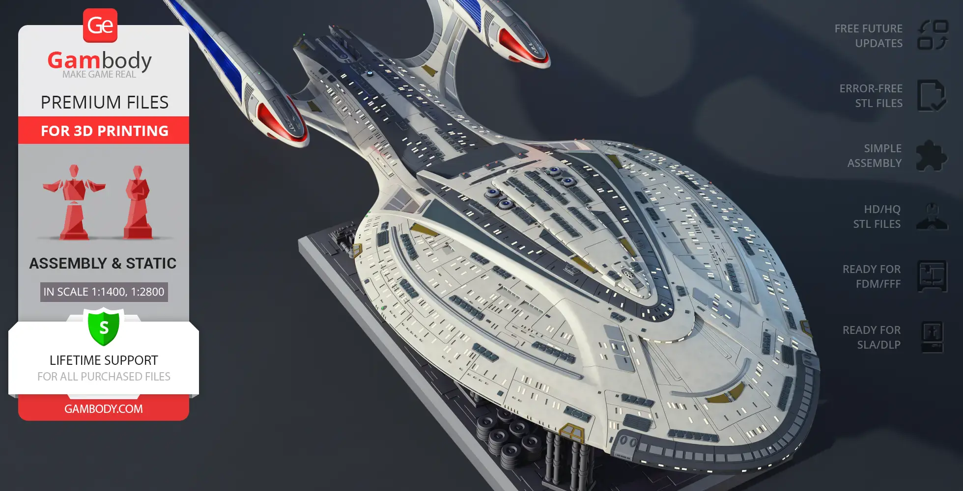
Features
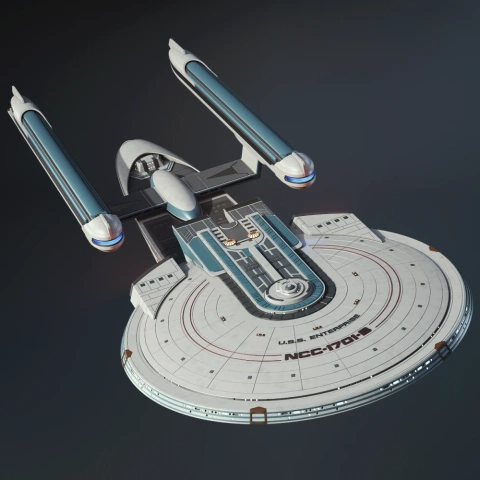
- Two hull options: clean and with lettering & markings
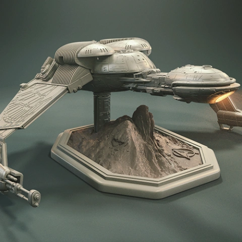
- Adjustable support arms on the display stand
- Saucer section can be separated from the stardrive section
- Removable rear shuttlecraft
- Modular display to showcase the saucer and stardrive sections independently
- The 3D printing model has tunnels for LED wiring.
DLP/SLA
Assembly method
Connectors
Features
- Two hull options: clean and with lettering & markings
- Adjustable support arms on the display stand
- Saucer section can be separated from the stardrive section
- Removable rear shuttlecraft
- Modular display to showcase the saucer and stardrive sections independently
- The 3D printing model has tunnels for LED wiring.
Additional details
Part of diorama
No
Special pack included
No
You will get instant access to the STL files of USS Enterprise NCC-1701-F 3D Printer Files | Assembly after completing your purchase. Simply add the model to your cart and check out using PayPal, credit or debit card, Apple Pay, Google Pay, Alipay, or other available payment methods.
Watch the assembly video for USS Enterprise NCC-1701-F 3D Printer Files | Assembly, and explore more tutorials, behind-the-scenes content, 3D printing timelapses, and painting guides on the official Gambody YouTube channel.
This 3D model comes with StereoLithography (.STL) files optimized for 3D printing. You'll get digital files, not a physical product
Before printing, take a look at Printing Details for recommended settings and tips to achieve better results.
USS Enterprise NCC-1701-F 3D Printer Files | Assembly includes 2 version(s) for the supported 3D printer type(s): FFF/FDM, DLP/SLA. Files are available for download after purchase.
See the Description and Specifications sections for more details about this model.
3D model history
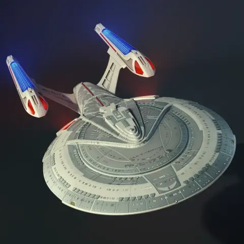
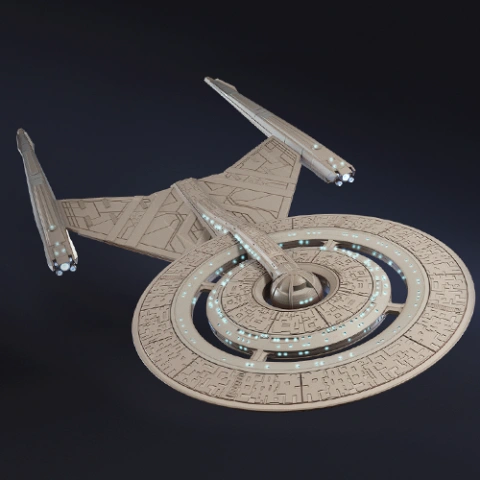
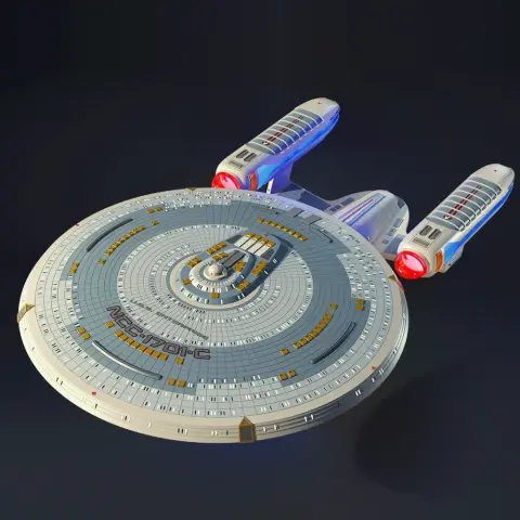
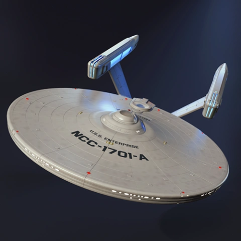
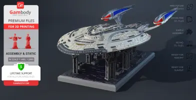
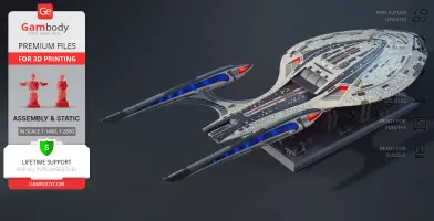
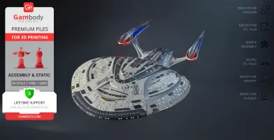
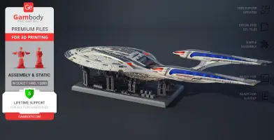
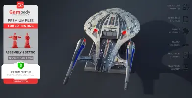
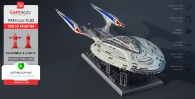
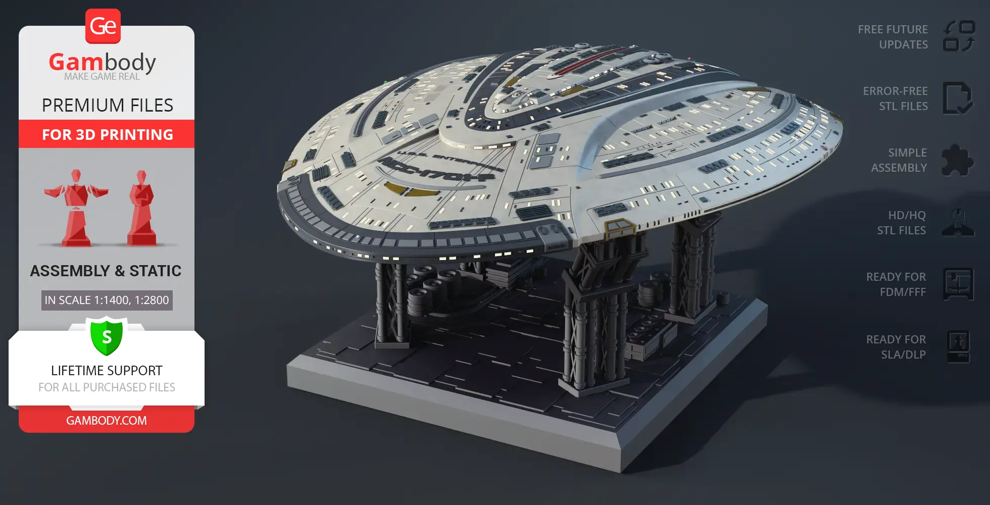
Designed to represent a new era of Starfleet, the USS Enterprise NCC-1701-F embodies scale, innovation, and prestige within the Star Trek universe. This flagship starship continues the legendary Enterprise lineage, standing alongside the most iconic vessels ever introduced in Star Trek TV series history.
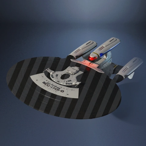
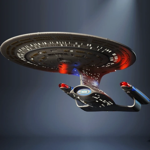
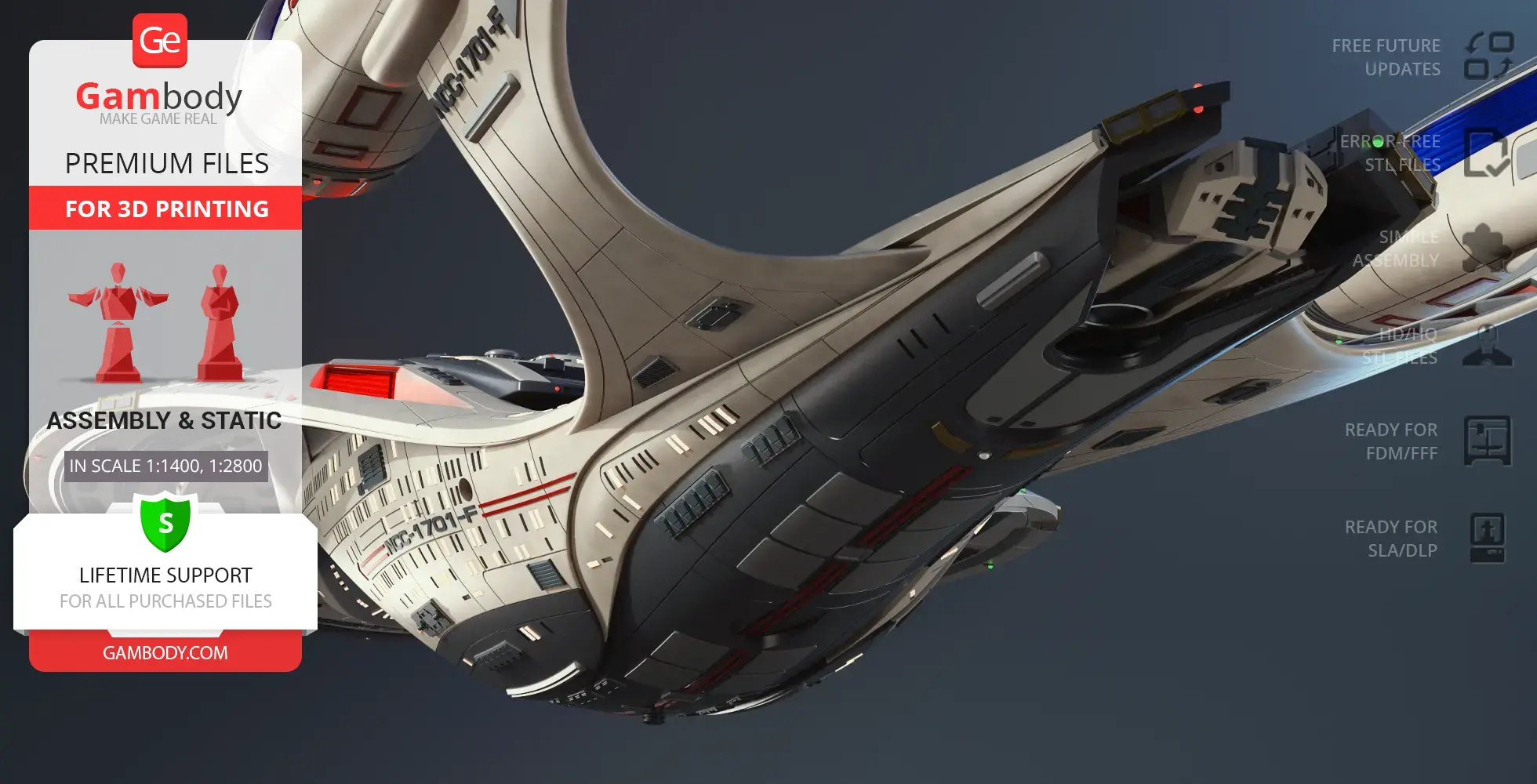
This USS Enterprise NCC-1701-F 3D model is built with exceptional precision and inspired by official USS Enterprise NCC-1701-F specs. As a highly detailed 3D model Enterprise, it features optional hull variations, allowing builders to choose between a version with registry markings or a clean hull without text. Select windows are designed as transparent elements, while others remain solid, adding realism and depth to the finished 3D printed USS Enterprise.
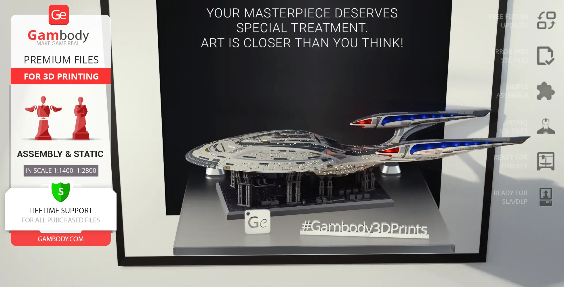
Engineered specifically for advanced USS Enterprise 3D print projects, this 3D model of a spaceship supports interior lighting, including cabin illumination, warp engine lighting, and rear nacelle glow. The hull is designed to separate into two main sections — the saucer and the main body — connected via secure snap-fit joints, offering flexibility in assembly and display. As a premium starship STL, the model is ideal for experienced makers and collectors of sci fi 3D print projects.
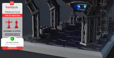
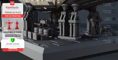
The display stand is styled as a space maintenance station, elevating the model among professional-grade spacecraft 3D models. The stand can be reconfigured into two independent sections, allowing the ship to be displayed in a split-flight configuration, with the saucer separated from the main hull. Adjustable support arms feature movable clamps that adapt to the curvature of the ship, ensuring a stable and dynamic presentation. Whether showcased with other TV series 3D models, displayed alongside movie 3D models, or featured as a centerpiece build, this USS Enterprise NCC-1701-F 3D model delivers a striking and immersive Star Trek display.
3D printing model features
Model-specific features:
- Two hull options: clean and with lettering & markings
- Adjustable support arms on the display stand
- Saucer section can be separated from the stardrive section
- Removable rear shuttlecraft
- Modular display to showcase the saucer and stardrive sections independently
- The 3D printing model has tunnels for LED wiring.
Printing & assembly details:
- Provided as error-free STL files compatible with most 3D printers;
- Optimized part division minimizes support material and ensures smooth and precise surface detailing;
- The assembly parts in the FFF/FDM version come in the recommended print orientations for easy bed placement;
- Assembly manual in PDF and video formats is included for the FFF/FDM and DLP/SLA versions;
- The model is available in recommended scales — 1/1400 for the FFF/FDM version and 1/2800 for the DLP/SLA/SLS versions.
What will you get after purchase?
- 2 versions of the USS Enterprise NCC-1701-F STL files for FFF/FDM, DLP/SLA - 130 files for all versions are available for download after the purchase;
- STL files of high-poly USS Enterprise NCC-1701-F for 3D printing consist of ----files;
- Sizes for:
- FFF/FDM Model Size: 250 mm wide, 102 mm high, 712 mm deep;
- FFF/FDM Platform Size: 176 mm wide, 108 mm high, 352 mm deep;
- DLP/SLA/SLS Model Size: 125 mm wide, 51 mm high, 356 mm deep;
- DLP/SLA/SLS Platform Size: 88 mm wide, 54 mm high, 176 mm deep;
- Assembly Manual for 1.0 FFF/FDM and 1.0 DLP/SLA versions in PDF and video formats;
- Detailed settings that we provide as a recommendation for Bambu Studio, Cura, Orca Slicer, PrusaSlicer, Simplify3D, and Slic3r for the best print;
- Full technical support from the Gambody Support Team.
Average customer rating (7 reviews)
4.5
Ratings breakdown
Click a star rating to filter reviews
Overall experience
Level of detail in the model
4.5
Model cut quality and assembly guide
4.5
Clarity and accuracy of the model page
4.5
Level of detail in the model
4.5
Model cut quality and assembly guide
4.5
Clarity and accuracy of the model page
5
If you have any additional ideas or reference materials you’d like to share, please feel free to reach out – we’re always glad to hear from you.
Level of detail in the model
4.8
Model cut quality and assembly guide
4.9
Clarity and accuracy of the model page
4.7
We forwarded your feedback to our Moderation Team, and they reviewed parts 25-28. According to their check, the dimensions of these parts are correct in the model files.
If parts 27 and 28 seem slightly too long, this is most likely related to the printing process rather than the files themselves. Small differences in environmental conditions, slight over-extrusion, material expansion, dimensional inaccuracies along the print axis, or minor differences in printer calibration can all affect the final fit. Lightly sanding the ends, as you did, is the right way to achieve a clean fit in this case.
If you notice any other fit-related issues during the build or have any other questions, please feel free to let us know – we’ll be happy to assist.
Level of detail in the model
5
Model cut quality and assembly guide
3.5
Clarity and accuracy of the model page
2.9
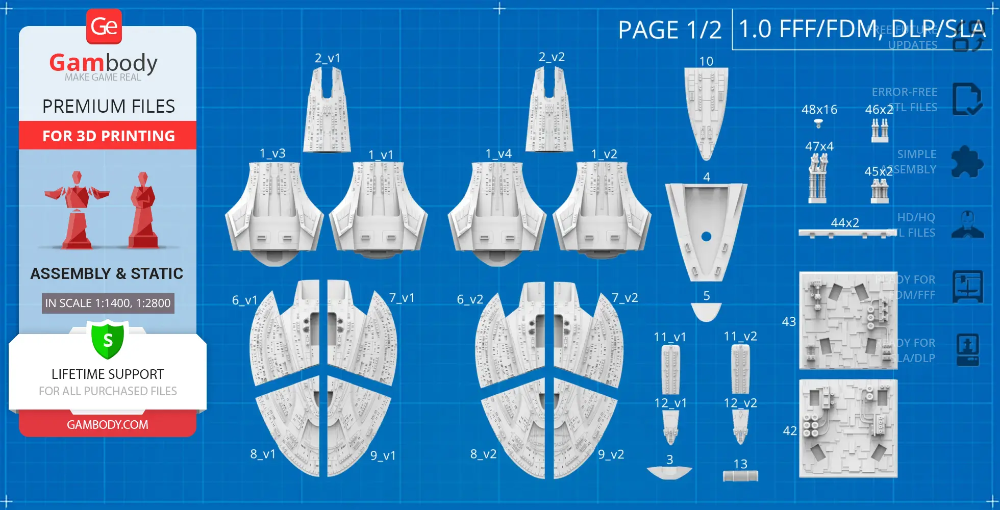
There are 4 star drive configurations because the model includes both split and one-piece versions, and each of those is available in both lettered and clean (blank) options.
The four versions are:
01_V1_mainPartShip_a_FDM — split, clean
01_V2_mainPartShip_a_FDM — split, lettered
01_V3_mainPartShip_a_FDM — one-piece, clean
01_V4_mainPartShip_a_FDM — one-piece, lettered
For clarity, we are also attaching a fragment of the PDF assembly manual, where this distinction is shown visually.
These additional versions are included simply to give you more flexibility depending on your printing preferences and the final look you want to achieve.
If you have any other questions while choosing the version, or during the printing and assembly process, please feel free to reach out – we’ll be happy to help.
Level of detail in the model
5
Model cut quality and assembly guide
5
Clarity and accuracy of the model page
5
We have reviewed the issue with our Moderation Team, and the engineers have already updated files #42–44 for both the FFF/FDM and DLP/SLA adapted "1.0 – Initial" versions. Because of this update, a correction to the assembly manual is no longer necessary.
If you have already printed the hull and still need pins that fit the previous version of parts #42–44, please let us know. We have prepared a separate set of pins specifically for the earlier version of those parts and will be glad to provide them for you.
Level of detail in the model
3.6
Model cut quality and assembly guide
4.6
Clarity and accuracy of the model page
4.7
We agree that using magnetic connectors is one of the most elegant and practical solutions for lighting this starship while preserving its modular design.
There are several approaches to powering the saucer section and the secondary hull. If you prefer to keep them detachable, as originally intended by the designer, Danny Lee, the most straightforward method is to use independent power sources. Alternatively, as you suggested, implementing a connector system (including magnetic connectors) between the saucer and the stardrive section allows power transfer while maintaining separability.
Your suggestion to introduce a dedicated internal lighting channel between the hull and the saucer has been forwarded to the author and documented for consideration in future updates. In the meantime, a similar solution can also be achieved by creating a custom channel directly in your slicer prior to printing.
Thank you again for your valuable input – insights like yours help improve both the models and the overall experience for the community.
Level of detail in the model
5
Model cut quality and assembly guide
5
Clarity and accuracy of the model page
5
Would be nice to have option parts for 1&2 without holes for part 50.
It also be would be nice if parts 4, 10, 6 and 7 had a channel to pass wires for lighting, and a "fixed Saucer" adapter version of part 10.
Regarding part #50: this element represents the phaser cannon turret. While it may not be clearly visible in every reference, it is part of the intended design, and in certain views its presence can be identified by the outline or shadow created by the protruding geometry.
That said, we fully understand your preference for a cleaner exterior. If you’d like to build the model without this element, there are several possible options. We can look into providing an alternative solution such as a flush cover or a simplified insert for the opening, or even custom variants of the relevant parts without the mounting hole for part #50.
As for lighting and wiring, this can be approached in two ways, depending on your workflow:
- Adding wire channels directly in your slicer using standard tools.
- Letting us know the exact locations and required diameters, so we can review this and suggest a cleaner solution.
Regarding a fixed saucer adapter version of part #10: if you don’t plan to separate the saucer section, the simplest approach is to permanently secure it using the existing locking features along with adhesive.
If you’d like to move forward with any specific customization, please feel free to share the exact configuration you have in mind – we’ll be happy to review it and assist further.
Level of detail in the model
3.8
Model cut quality and assembly guide
4
Clarity and accuracy of the model page
4.2
For a die-hard fan, this model is an absolute must-have.
It's a faithful recreation and even has the option to add internal lighting. I highly recommend it and I'm going to add it to my slicer right now!
Below you'll find detailed slicing settings for Bambu Studio 2.0+, Orca Slicer 2.0+, UltiMaker Cura 5.0+, PrusaSlicer 2.0+, Slic3r 1.3+, Simplify3D 5.0+ to help you get the best results when printing this model. These settings are optimized specifically for this 3D model, but please note they may need slight adjustments depending on your printer or filament. When in doubt, refer to your printer's user manual.
To avoid printing issues and achieve the best quality, we highly recommend applying the following settings:
For better quality use 0.12 mm layer height, for fast printing use 0.2 mm layer height. For pins and the Ge connectors, use 0.2 layer height.
120-150% of your Layer Height
But you can paint the seam if you want.
You have to calibrate this parameter
You have to calibrate this parameter
You have to calibrate this parameter
For pins and power elements of the structure, such as the vehicle frame, use 3 loop
Disabled for vehicles and enabled for characters
For 0,2 Layer Height
The parameters in this tab vary greatly, it all depends on the quality of your printer. For example, if you have a classic Ender3, stick to the minimum parameters, but if you have a newer printer, for example Anycubic cobra 3 v2, you can select the maximum recommended values
Settings for advanced users, change these parameters only if you have sufficient 3D printing expertise
Enable this parameter if your model requires supports
We also recommend placing and removing supports manually in some places using special button
1-2 loops for more thick support
Top Z distance = 1-1.3 layer Height. If the supports are hard to remove, try increasing this setting by 0.1-0,4 mm
Bottom Z distance = 1-1.3 layer Height. If the supports are hard to remove, try increasing this setting by 0.1-0,4 mm
You have to calibrate this parameter which one is better for your filament
Increase this parameter if the supports are hard to remove from walls
For PLA and PETG filament types
5-8 mm is optional for small prints that have bad adhesion to the build plate
You have to calibrate this parameter
Read the description on your filament roll
Read the description on your filament roll and increase this parameter for fast printers
Read the description on your filament roll and increase this parameter for fast printers
For better quality use 0.12 mm layer height, for fast printing use 0.2 mm layer height. For pins and the Ge connectors, use 0.2 layer height.
120-150% of your Layer Height
But you can paint the seam if you want.
0.01-0.05 You have to calibrate this parameter
0.01-0.05 You have to calibrate this parameter
0.1-0.2 You have to calibrate this parameter
For pins and power elements of the structure, such as the vehicle frame, use 3 loop
Disabled for vehicles and ships, enabled for characters
For 0,2 Layer Height
For 0,2 Layer Height
The parameters in this tab vary greatly, it all depends on the quality of your printer. For example, if you have a classic Ender3, stick to the minimum parameters, but if you have a newer printer, for example, Anycubic Kobra 3 Or Bambulab A1, you can select the maximum recommended values.
Settings for advanced users, change these parameters only if you have sufficient 3D printing expertise
Enable this parameter if your model requires supports
We also recommend placing and removing supports manually in some places using special button
Top Z distance = 1-1.3 layer Height. If the supports are hard to remove, try increasing this setting by 0.1-0,4 mm
Bottom Z distance = 1-1.3 layer Height. If the supports are hard to remove, try increasing this setting by 0.1-0,4 mm
Increase this parameter if the supports are hard to remove from walls
For PLA and PETG filament types
5-8 mm is optional for small prints that have bad adhesion to the build plate
Read the description on your filament roll
Read the description on your filament roll and increase this parameter for fast printers
You have to calibrate this parameter
Read the description on your filament roll and increase this parameter for fast printers
Read the description on your filament roll
This field is filled in according to your printer specifications when you add it to the slicer.
You can add custom G-code here for the start and end of the print. However, be careful - this is for advanced users only!
You have to calibrate your printer using Ge retraction test models
Retraction Length: For direct-drive setups use 0.5 mm to 2.5 mm; for Bowden extruders use 5 to 7 mm
This is how fast the filament is pulled back—40-60 mm/s for direct drive and 30-50 mm/s for Bowden setups.
You have to calibrate this parameter: Reduce it until the printer starts to hit the parts with the nozzle during printing, then increase it by 0.2.
For better quality use 0.12 mm layer height, for fast printing use 0.2 mm layer height. For pins and the Ge connectors, use 0.2 layer height.
120-150% of your Layer Height
To increase the strength of the print parts, use wall line count: 3
For pins and connectors use 50% Infill
These parameters are for standard PLA plastic. If you are using a different type of plastic, check the printing temperature recommended by the manufacturer. Also, read the description on your filament spool. For fast printers, add +30 °C to the current parameters.
The parameters in this tab vary greatly, it all depends on the quality of your printer. For example, if you have a classic Ender3, stick to the minimum parameters, but if you have a newer printer, for example Anycubic cobra 3 v3, you can select the maximum recommended values
Settings for advanced users, change these parameters only if you have sufficient 3D printing expertise.
You need to calibrate this parameter using Gambody test models. These values are average values for a Direct Drive extruder; for a Bowden extruder, the values should be increased.
You need to calibrate this parameter using Gambody test models. These values are average values for a Direct Drive extruder; for a Bowden extruder, the values should be increased.
Use this value other than 0 if your nozzle catches on the internal infill during travel moves. Try to keep this value as low as possible in height.
Use normal supports to support large, straight surfaces (most mechanical or technical parts).
You have to calibrate this parameter according to the capabilities of your printer and your filament, using a Gambody test models.
Use 1 instead of 0 if your supports are thin and tall. They will be harder to remove, but much stronger.
Top Z distance = 1-1.3 layer Height. If the supports are hard to remove, try increasing this setting by 0.1-0,4 mm
Increase this parameter if the supports are hard to remove from walls
Use tree supports to support complex objects, such as characters.
You have to calibrate this parameter according to the capabilities of your printer and your filament, using a Gambody test models.
Top Z distance = 1-1.3 layer Height. If the supports are hard to remove, try increasing this setting by 0.1-0,4 mm
Increase this parameter if the supports are hard to remove from walls
Use a skirt for all parts when printing on outdated printers.
Use a brim when printing thin but tall parts, as well as parts with a small bed adhesion area.
For better quality use 0.12 mm layer height, for fast printing use 0.2 mm layer height. For pins and the Ge connectors, use 0.2 layer height.
120-150% of your Layer Height
for 0.2 Layer Height
But you can paint the seam if you want.
(for PLA and PETG)
(5-8 mm is optional for small prints that have bad adhesion to the build plate)
Enable this parameter if your model requires supports
(45-50 degree)You have to calibrate this parameter according to the capabilities of your printer
and your filament, using a Gambody test models.
Top contact Z distance = 1-1.3 layer Height. If the supports are hard to remove, try
increasing this setting by 0.1-0,4 mm
Top contact Z distance = 1-1.3 layer Height. If the supports are hard to remove, try
increasing this setting by 0.1-0,4 mm
Increase this parameter if the supports are hard to remove from walls
The parameters in this tab vary greatly, it all depends on the quality of your printer. For example, if you have a classic Ender3, stick to the minimum parameters, but if you have a newer printer, for example Anycubic cobra 3 v3, you can select the maximum recommended values
Settings for advanced users, change these parameters only if you have sufficient 3D printing expertise. Use the minimum value for outdated printers without acceleration calibration, and the maximum value for modern printers if you need it.
These settings only work for 3D printers with multiple extruders
You can try setting all parameters in this section, except the First layer, to values between 0.75% of your nozzle diameter and 1.25% of your nozzle diameter. Adjusting them will help you work out the optimal parameters for the best quality for your print. As for the First layer, you can set it to 150% of the diameter of your nozzle for better adhesion to the build plate (for a nozzle with a diameter of 0.4 mm, the First layer extrusion width can be from 0.3 mm to 0.5 mm)
For better printing quality you have to calibrate this parameter using Gambody test model.
Check your filament manufacturer's temperature recommendations on the spool.
Cooling parameters depends on the material you use for printing.
*for PLA
For better quality use 0.12 mm layer height, for fast printing use 0.2 mm layer height. For pins and the Ge connectors, use 0.2 layer height.
120-150% of your Layer Height
For 0.12 Layer Height
For 0.12 Layer Height
For pins and connectors use 50% Infill
Use skirt for outdated 3d printers
(5-8 mm is optional for small prints that have bad adhesion to the build plate)
Enable this parameter if your model requires supports
(45-60 degree)You have to calibrate this parameter according to the capabilities of your printer and your filament, using a Gambody test models
Contact Z distance = 1-1.3 layer Height. If the supports are hard to remove, try increasing this setting by 0.1-0,4 mm
The parameters in this tab vary greatly, it all depends on the quality of your printer. For example, if you have a classic Ender3, stick to the minimum parameters, but if you have a newer printer, for example Anycubic cobra 3 v3, you can select the maximum recommended values
Settings for advanced users, change these parameters only if you have sufficient 3D printing expertise. Use the minimum value for outdated printers without acceleration calibration, and the maximum value for modern printers if you need it.
You have to calibrate this parameter from 0.9 to 1.1 according to the capabilities of your printer and your filament, using a Gambody test models.
Check your filament manufacturer's temperature recommendations on the spool.
Cooling parameters depends on the material you use for printing.
Calibrate this value if you need to reduce or improve the adhesion between the plastic and the heat bed
Your current nozzle diameter
You need to calibrate this parameter using Gambody test models. These values are average values for a Direct Drive extruder; for a Bowden extruder, the values should be increased.
Your current nozzle diameter
You have to calibrate this parameter using Gambody test models.
You need to calibrate this parameter using Gambody test models. These values are average values for a Direct Drive extruder; for a Bowden extruder, the values should be increased.
For better quality use 0.12 mm layer height, for fast printing use 0.2 mm layer height. For pins and the Ge connectors, use 0.2 layer height.
For 0,2 Layer Height
For 0,2 Layer Height
To increase the strength of the print parts, use Outline Perimeters: 3
You can enable this parameter to print rounded or spherical models, as well as character models.
Use this option only if your parts are too tight. but better calibrate your printer extrusion
Use this option only if your parts are too tight. but better calibrate your printer extrusion
Use 2 and more if you want to create skirt instead brim
1-2 for skirt and 10-20 for brim
Use for wipe nozzle if you need
Use For ABS filament
For pins and connectors use 50% Infill
Top Z distance = 1-1.3 layer Height. If the supports are hard to remove, try increasing this setting by 0.1-0,4 mm
Calibrate your filament and detect optimal temperature for it
Average temperature for PLA filament
The parameters in this tab vary greatly, it all depends on the quality of your printer. For example, if you have a classic Ender3, stick to the minimum parameters, but if you have a newer printer, for example Anycubic cobra 3 v3, you can select the maximum recommended values
Settings for advanced users, change these parameters only if you have sufficient 3D printing expertise.
DLP/SLA
- Two hull options: clean and with lettering & markings
- Adjustable support arms on the display stand
- Saucer section can be separated from the stardrive section
- Removable rear shuttlecraft
- Modular display to showcase the saucer and stardrive sections independently
- The 3D printing model has tunnels for LED wiring.
FFF/FDM
- Two hull options: clean and with lettering & markings
- Adjustable support arms on the display stand
- Saucer section can be separated from the stardrive section
- Removable rear shuttlecraft
- Modular display to showcase the saucer and stardrive sections independently
- The 3D printing model has tunnels for LED wiring.