


Files
3D model format
Stereolithography (.stl)
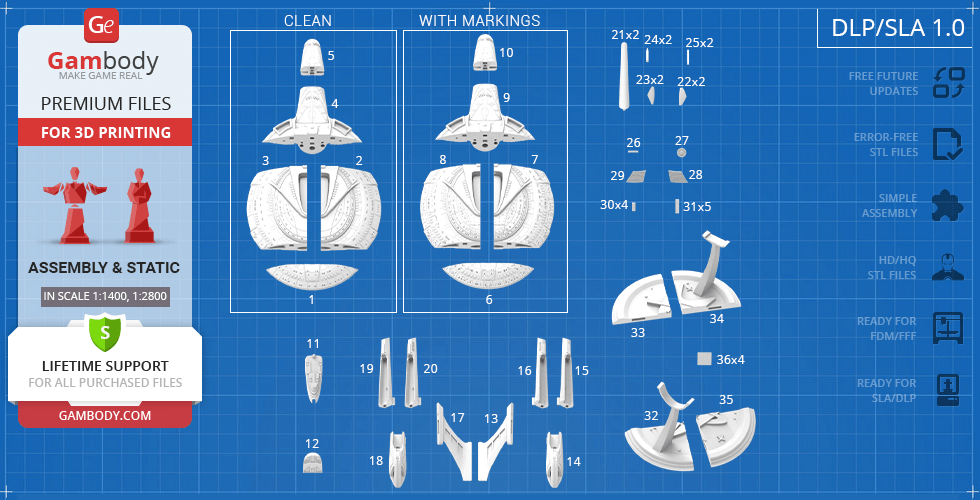
Total files
Slicer settings
Mesh error check
Netfabb
Support
Lifetime support from Gambody team
Update requests
Available to verified buyers
Model complexity
Standard: balanced printing difficulty and moderate part count with assembly steps.
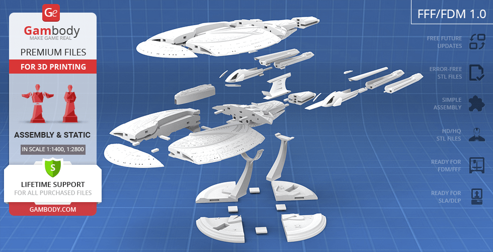
Model versions
FFF/FDM
Assembly method
Connectors, Glue
Features
- Fully upgraded version of the model with enhanced surface detailing and reworked panel lines.
- Increased 935 mm large-scale format for precise detailing.
- Reworked captain's bridge and integrated shuttle bay with a miniature shuttle.
- Two primary hull options for standard or clean (no lettering) finish.
- Comes with hollowed-out parts optimized for advanced LED illumination.
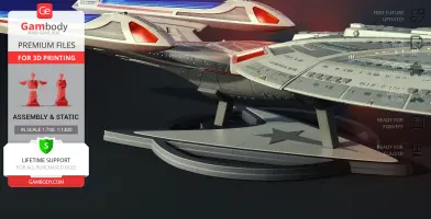
- Includes dedicated display pedestal.
- The assembly parts are connected using specially designed integrated connectors that fit securely into the corresponding slots. Optionally, for added strength and rigidity, the static connections can be glued together.
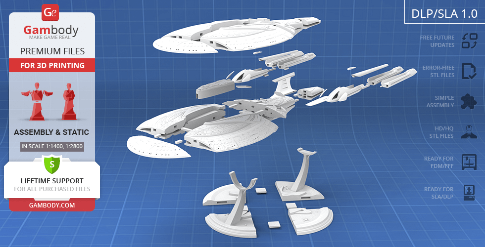
DLP/SLA
Eco parts
Assembly method
Connectors, Glue
Features
- Fully upgraded version of the model with enhanced surface detailing and reworked panel lines.
- Reworked captain's bridge and integrated shuttle bay with a miniature shuttle.
- Two primary hull options for standard or clean (no lettering) finish.
- Comes with hollowed-out parts optimized for advanced LED illumination.
- Includes dedicated display pedestal.
- The assembly parts are connected using specially designed integrated connectors that fit securely into the corresponding slots. Optionally, for added strength and rigidity, the static connections can be glued together.
FFF/FDM
Assembly method
Connectors, Glue
Features
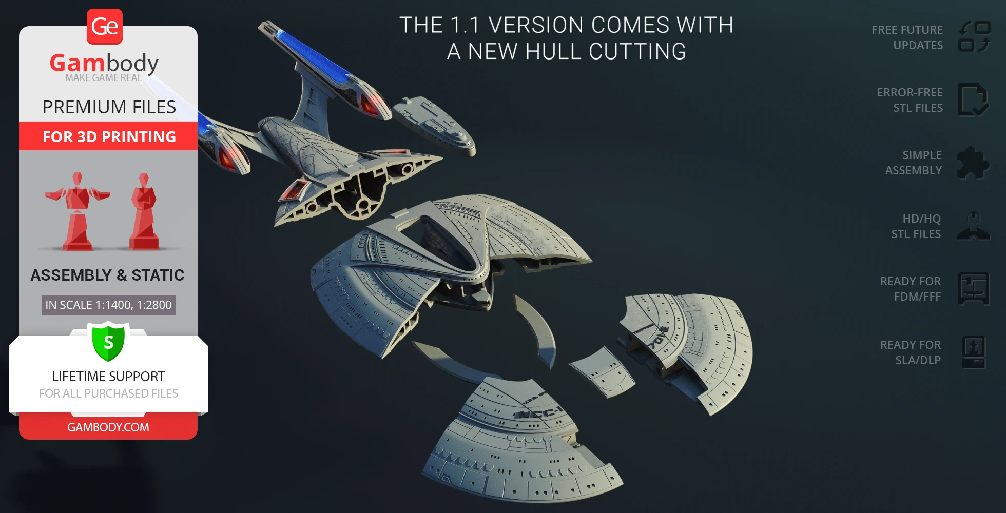
- Updated version of the model with improved structural features.
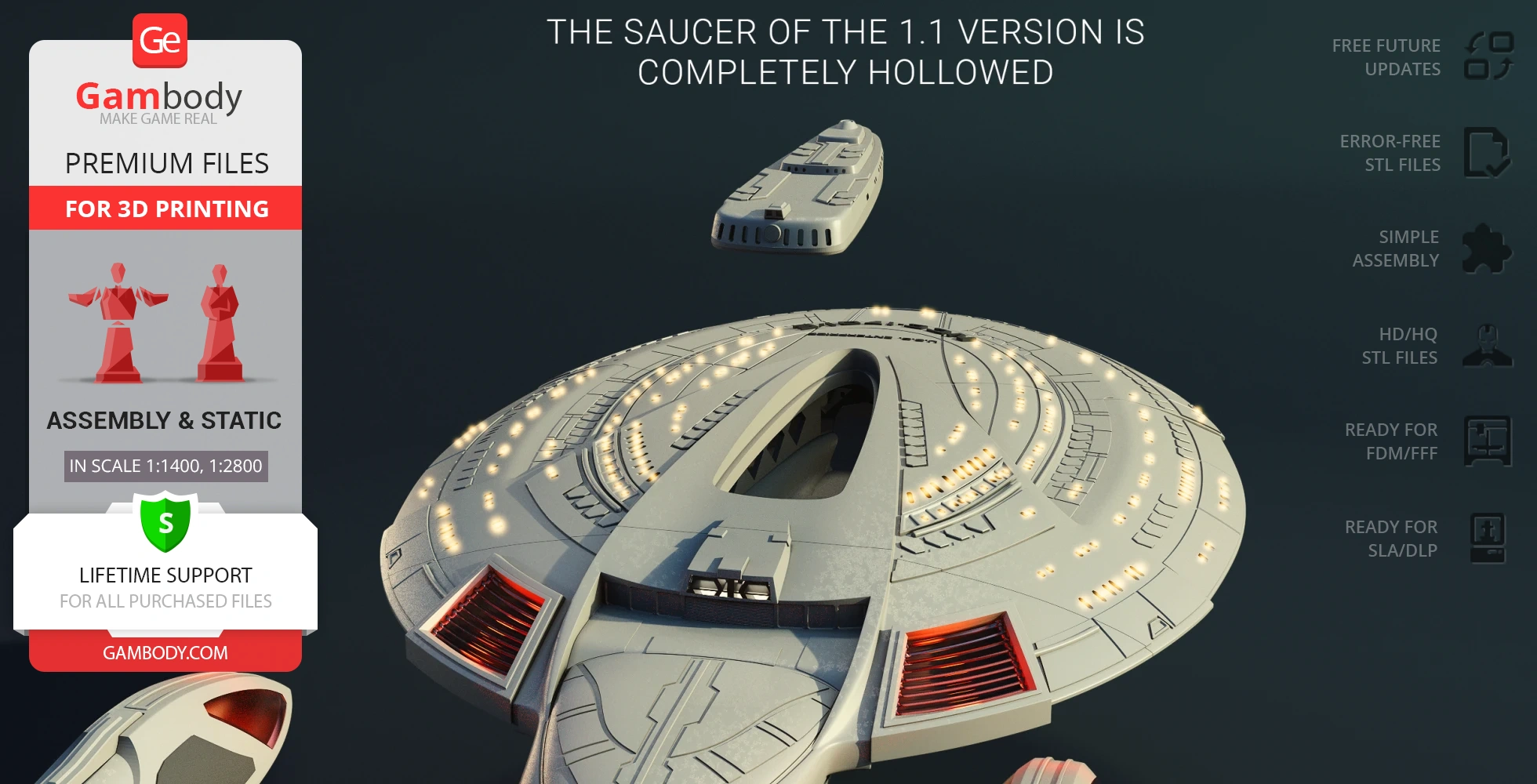
- Completely hollowed saucer section for easier wiring.
- Expanded number of hull viewports and windows for optional LED illumination.
- Updated hull cutting and optimized part breakdown to minimize generated support structures.
- The assembly parts are connected using specially designed integrated connectors; Optionally, for added strength and rigidity, the static assembly joints can be glued together.
DLP/SLA
Eco parts
Assembly method
Connectors, Glue
Features
- Updated version of the model with improved structural features.
- Completely hollowed saucer section for easier wiring.
- Expanded number of hull viewports and windows for optional LED illumination.
- Updated hull cutting and optimized part breakdown to minimize generated support structures.
- The assembly parts are connected using specially designed integrated connectors; Optionally, for added strength and rigidity, the static assembly joints can be glued together.
FFF/FDM
Assembly method
Connectors, Glue
Features
- Initial version of the model.
- Features parts with raised markings/patterns and clean parts.
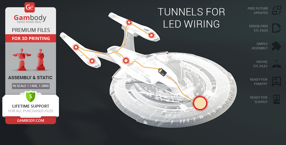
- Standard tunnels for LED wiring in engine ports, nacelle pylons, and viewports.
- Includes custom parts with edited internal tunnels for upscaling.
- The assembly parts are connected using specially designed integrated connectors; Optionally, for added strength and rigidity, the static assembly joints can be glued together.
DLP/SLA
Eco parts
Assembly method
Connectors, Glue
Features
- Initial version of the model.
- Features parts with raised markings/patterns and clean parts.
- Standard tunnels for LED wiring in engine ports, nacelle pylons, and viewports.
- The assembly parts are connected using specially designed integrated connectors; Optionally, for added strength and rigidity, the static assembly joints can be glued together.
Additional details
Part of diorama
No
Special pack included
No
You will get instant access to the STL files of USS Enterprise NCC-1701-E 3D Printer Files | Assembly after completing your purchase. Simply add the model to your cart and check out using PayPal, credit or debit card, Apple Pay, Google Pay, Alipay, or other available payment methods.
Watch the assembly video for USS Enterprise NCC-1701-E 3D Printer Files | Assembly, and explore more tutorials, behind-the-scenes content, 3D printing timelapses, and painting guides on the official Gambody YouTube channel.
This 3D model comes with StereoLithography (.STL) files optimized for 3D printing. You'll get digital files, not a physical product
Before printing, take a look at Printing Details for recommended settings and tips to achieve better results.
USS Enterprise NCC-1701-E 3D Printer Files | Assembly includes 2 version(s) for the supported 3D printer type(s): FFF/FDM, DLP/SLA. Files are available for download after purchase.
See the Description and Specifications sections for more details about this model.
3D model history
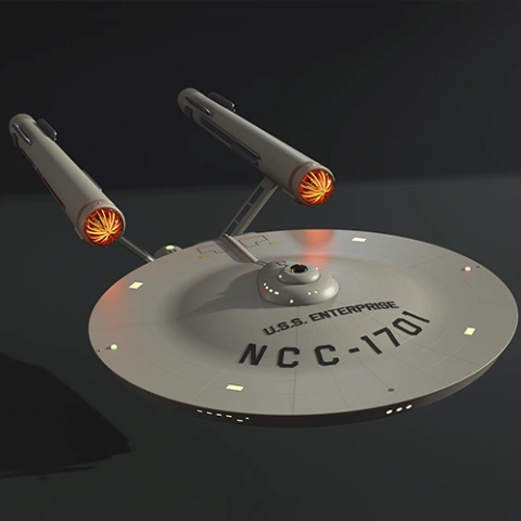
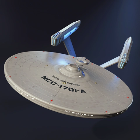
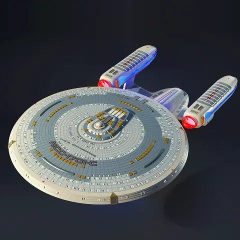
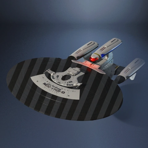
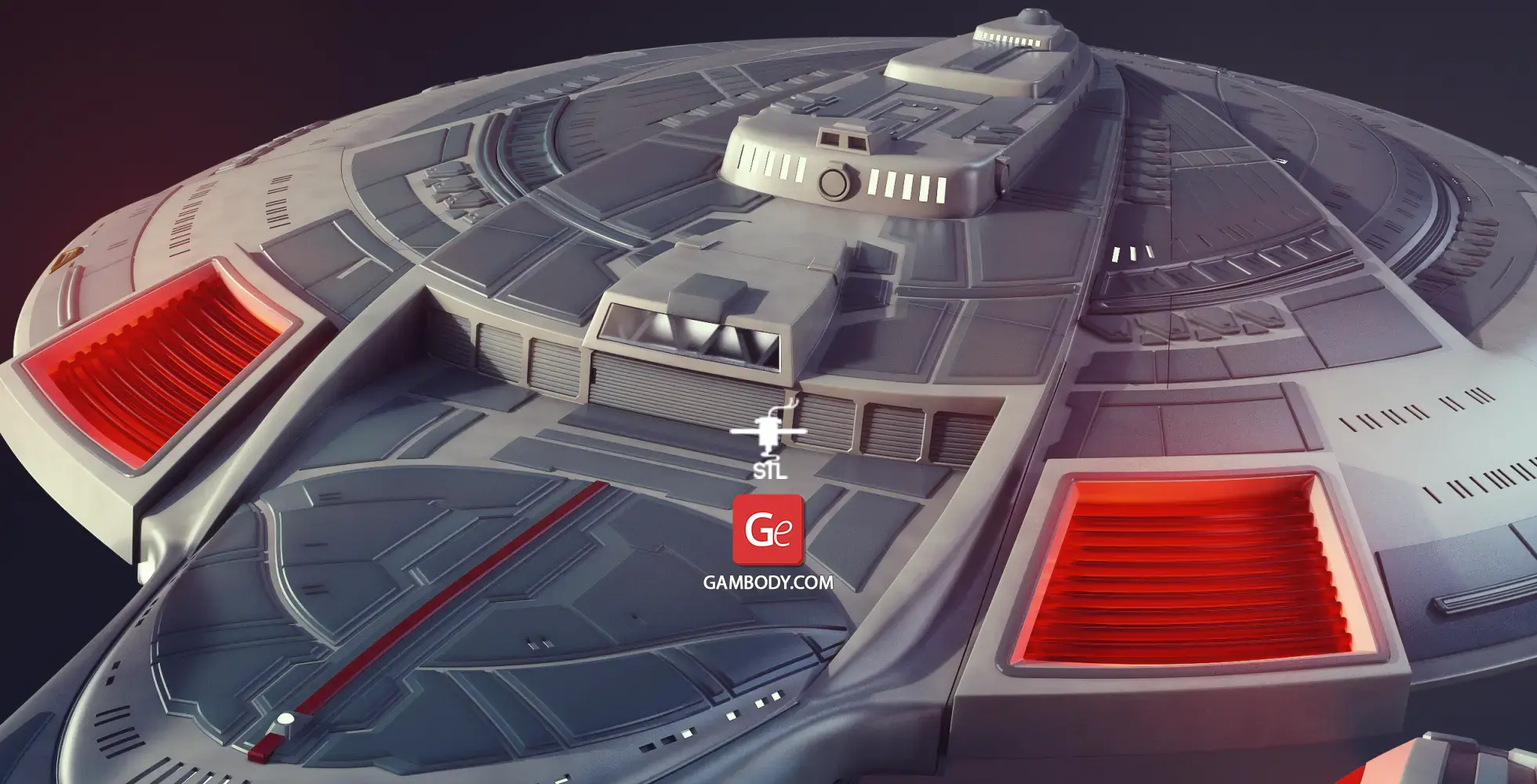
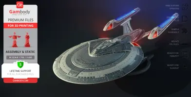
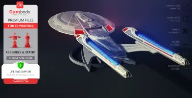
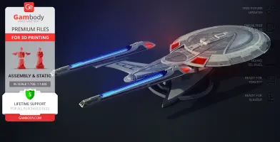
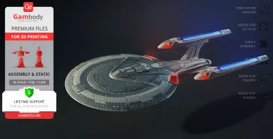
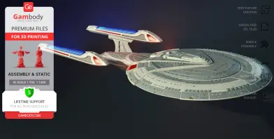
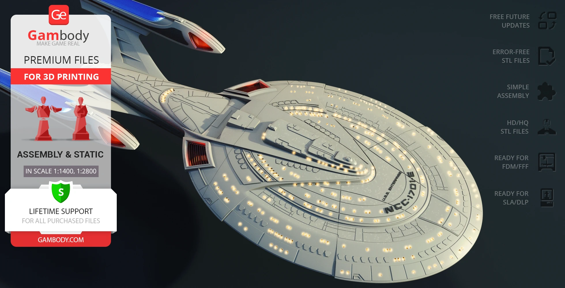
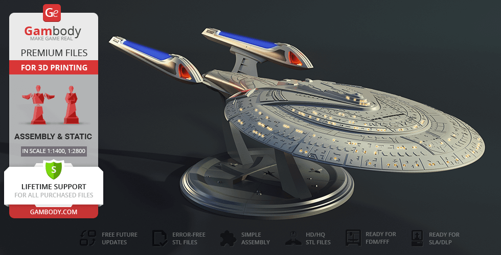
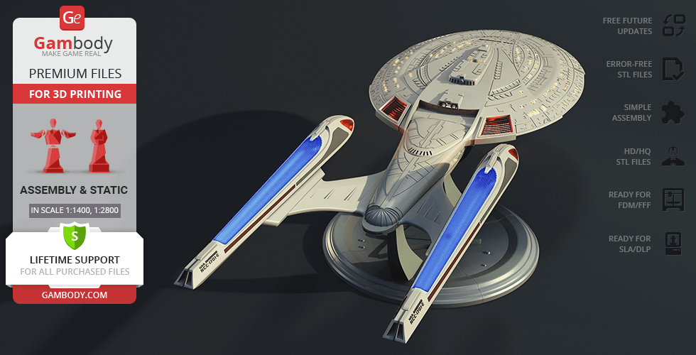
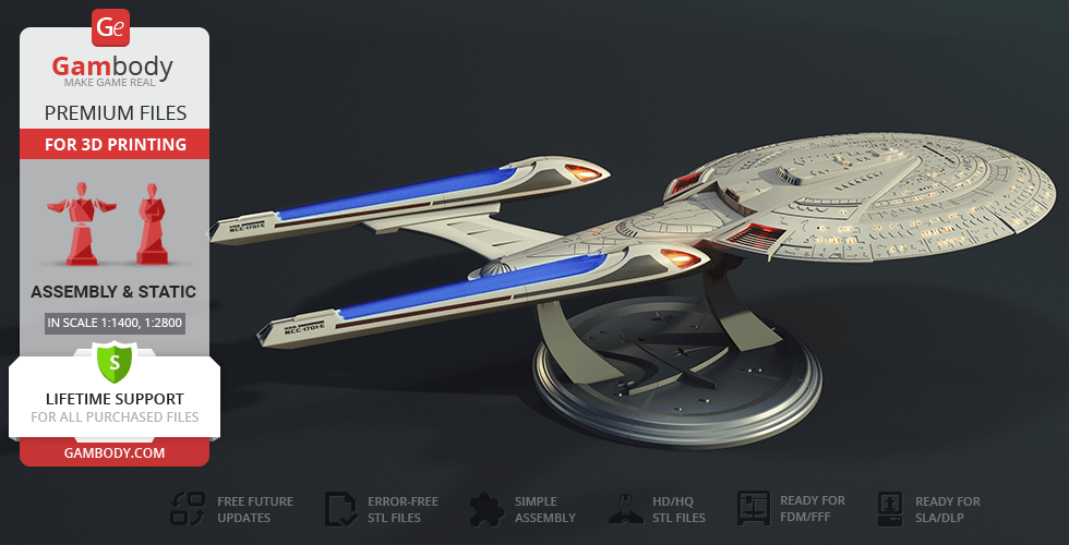
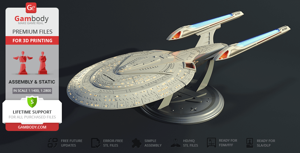
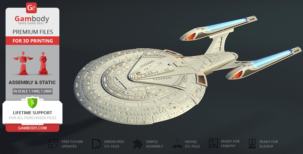
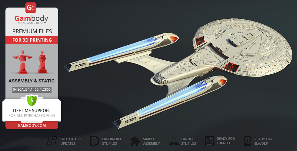
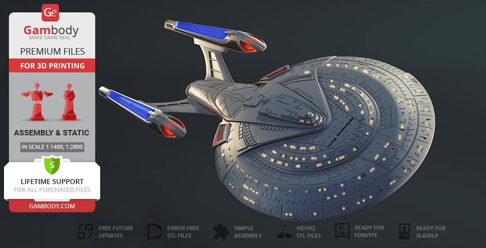
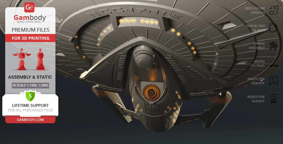
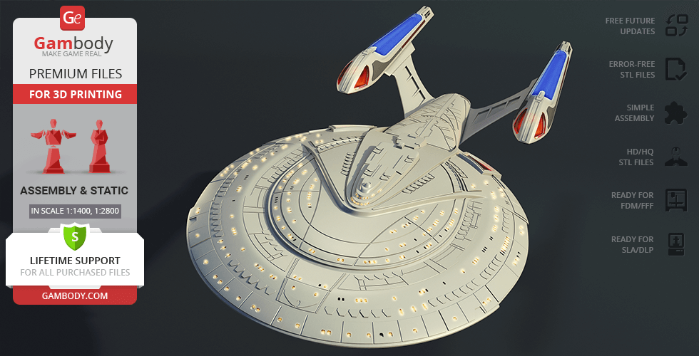
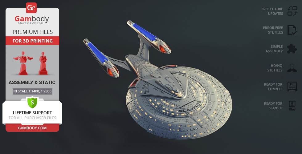
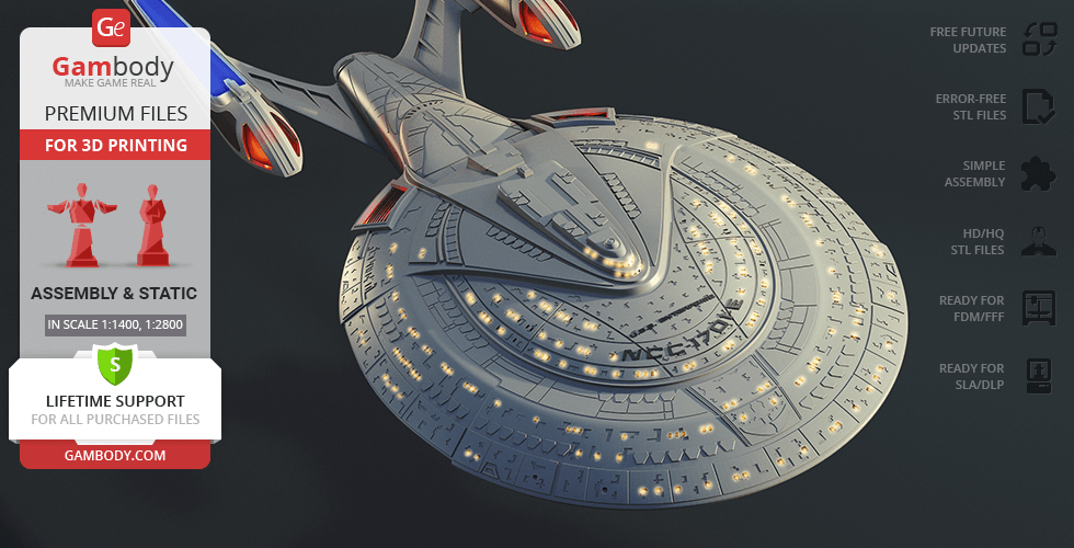
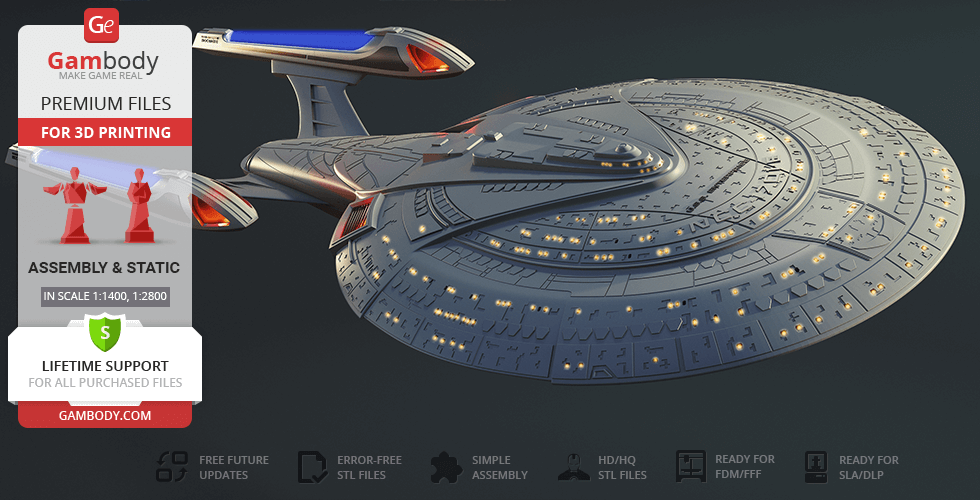
USS Enterprise NCC-1701-E - the legendary Federation flagship from the Star Trek Universe, built for exploration, defense, and missions where the fate of civilizations is at stake. Its sleek silhouette, refined hull lines, and powerful architecture make it one of the most iconic and revered spacecraft in science fiction.
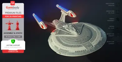
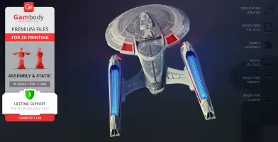
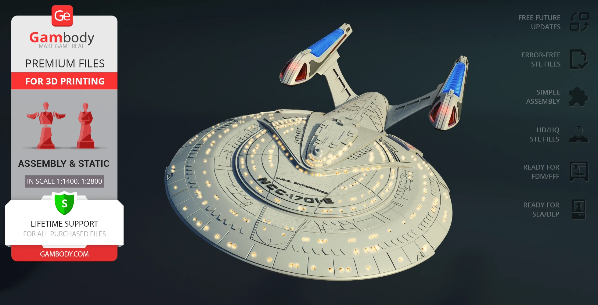
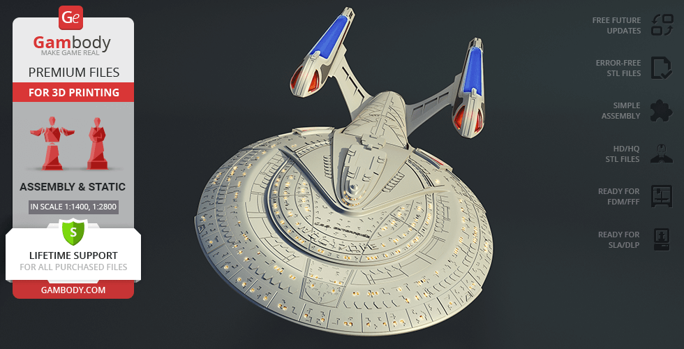
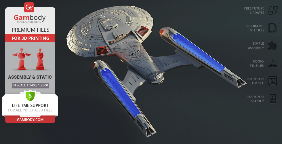
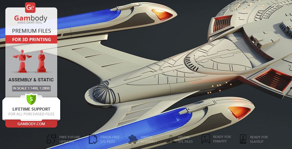
This USS Enterprise NCC 1701 E 3D model is created in an impressive large scale - reaching 935 mm in length - allowing for a level of detail that closely matches the canonical look of the ship. The primary hull (saucer section) features precise segmentation for clean assembly, while the entire structure is fully hollow inside, making it ideal for advanced lighting setups - exactly what fans expect from a high-end 3D print spaceship.
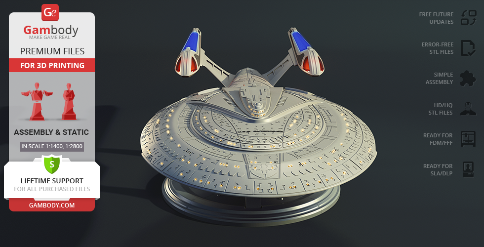
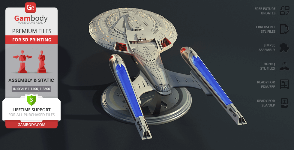
The hull includes a large number of windows, carefully arranged according to the original ship layout, enhancing the “alive” effect of a 3D printed spacecraft when LED lighting is installed. Surface detailing, panel lines, and structural elements are scaled appropriately, delivering the level of refinement expected from premium starship STL files.
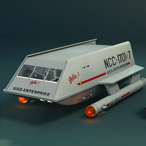
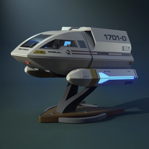
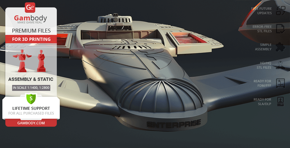
The captain’s bridge sections are carefully refined for the scale, a shuttle bay with shuttles is included, and the display stand ensures both stability and a striking presentation. The lighting system follows a canon-inspired approach: illuminated zones are placed in alignment with key ship areas - from living quarters to technical sections - creating the impression of a fully operational flagship within the world of 3D print sci fi.
These USS Enterprise STL files are perfect for collectors of iconic Star Trek 3D models and for those looking for a project inspired by legendary films - the kind often featured in movie 3d models selections. The model naturally becomes a centerpiece among spacecraft 3d models, drawing attention with its scale and realism. And the moment the lights come alive across the hull, revealing the ship’s silhouette in the dark, it is no longer just a 3D print model, but a true Federation flagship - ready to once again go where no one has gone before...
3D printing model features
Model-specific features:
- Features interchangeable hull options with and without lettering for a canonical or custom Starfleet display.
- Integrated shuttle bay assembly includes a miniature shuttle and highly detailed internal docking bay.
- Engineered with hollow parts and viewports specifically designed for advanced LED illumination.
- Removable battery covers are seamlessly integrated into the hull for easy compartment access without disrupting the silhouette.
- Supported by a specialized, multi-pronged display pedestal ensuring maximum stability for this massive starship.
Printing & assembly details:
- Provided as error-free STL files compatible with most 3D printers
- Optimized part division minimizes support material and ensures smooth and precise surface detailing
- The assembly parts in the FFF/FDM version come in the recommended print orientations for easy bed placement
- Assembly manual in PDF and video formats is included for the FFF/FDM and DLP/SLA versions
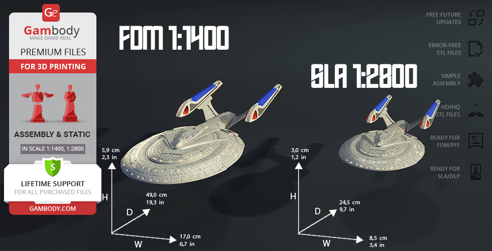
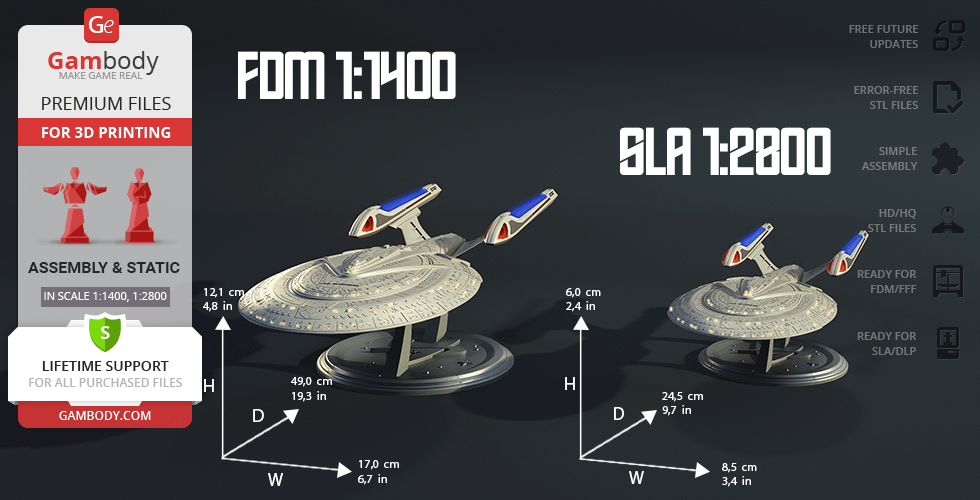
- Versions 2.0 is available in recommended scales — 1:700 for the FFF/FDM version and 1:1400 for the DLP/SLA/SLS versions
- Versions 1.0 and 1.1 have a scale of 1:1400 for the FFF/FDM version and 1:2800 for the DLP/SLA versions
What will you get after purchase?
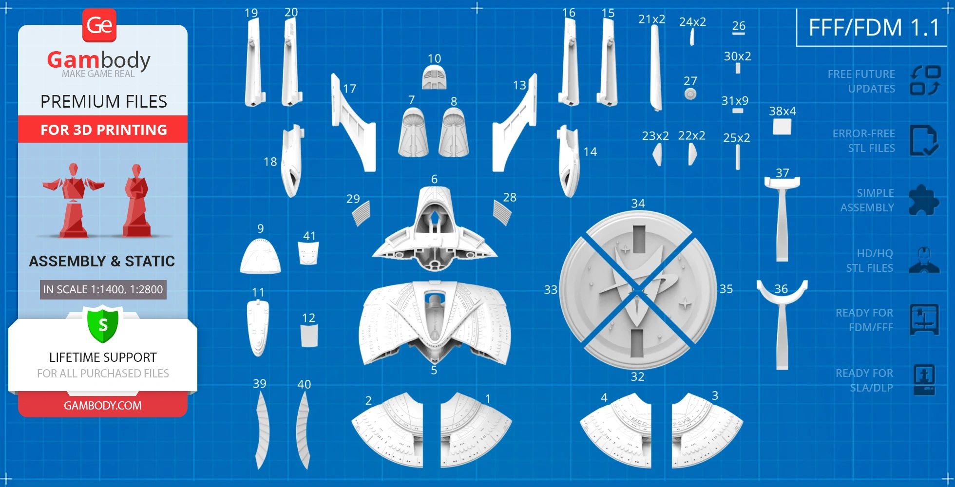
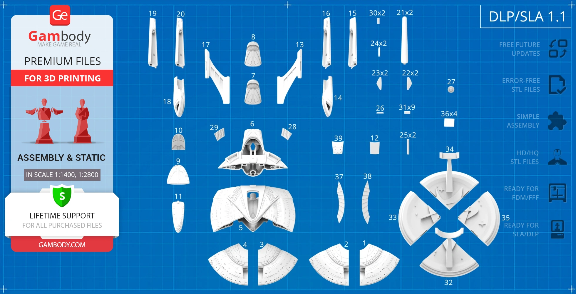
- 6 versions of USS Enterprise NCC-1701-ESTL files for FFF/FDM, DLP/SLA, DLP/SLA Eco, and SLS — files for all versions are available for download after the purchase;
- STL files of high-poly USS Enterprise NCC-1701-E model for 3D printing consist of 273 files;
- Sizes for:
- FFF/FDM Model Size: 326 mm wide, 113 mm high, 935 mm deep;
- FFF/FDM Platform Size: 276 mm wide, 106 mm high, 353 mm deep;
- DLP/SLA Model Size: 163 mm wide, 56 mm high, 468 mm deep;
- DLP/SLA Platform Size: 138 mm wide, 53 mm high, 177 mm deep;
- Assembly Manual for 1.0 and 2.0 FFF/FDM versions, as well as 2.0 and 1.0 DLP/SLA versions in PDF and video formats;
- Detailed settings that we provide as a recommendation for Bambu Studio, Cura, Orca Slicer, PrusaSlicer, Simplify3D, and Slic3r for the best print;
- Full technical support from the Gambody Support Team.
Average customer rating (19 reviews)
4.3
Ratings breakdown
Click a star rating to filter reviews
Overall experience
Level of detail in the model
4.2
Model cut quality and assembly guide
4.2
Clarity and accuracy of the model page
4.2
Level of detail in the model
4
Model cut quality and assembly guide
4
Clarity and accuracy of the model page
4
(01_bodyPart_a_Clear_FrontL、02_bodyPart_b_Clear_FrontR_、05_bodyPart_c_Mid_FDM)
Thank you for your thoughtful message and for sharing your idea about adding LED lighting to the USS Enterprise NCC-1701-E 3D Model.
Unfortunately, routing an LED strip in the exact location you described would weaken the structure of the model. For this reason, implementing this specific modification isn’t technically possible without compromising the integrity of the parts.
As an alternative, we recommend using the version specifically designed for LED lighting. The folder with LED-ready parts has now been opened for you. You can find it in the Source Files tab on the model’s page, under “1.0 Alternative version with LEDs,” as shown in the image below.
Please note that while this version uses the same scale, the part segmentation differs from the “1.1 Major modification” version. If you’ve already started printing some parts, we recommend keeping this in mind before proceeding further.
We always do our best to support you and help you achieve the best possible printing and assembly results based on your preferences. We hope this alternative works well for your project, and if you have any further questions or suggestions, please don’t hesitate to reach out — we’re always happy to help.
Level of detail in the model
5
Model cut quality and assembly guide
4.5
Clarity and accuracy of the model page
5
We've just checked the files, and as far as we can see, our Moderation Team corrected and replaced the affected files in the 2.0 Fully Upgraded version on May 14 for both FFF/FDM and DLP/SLA printing types.
It looks like you may be referring to files downloaded before this update, so we recommend re-downloading the following files from the 2.0 Fully Upgraded Version:
_02_V1_bodyPart_b_LeftF_FDM - clean version without lettering.
_02_V2_bodyPart_b_LeftF_FDM - version with the "E" letter.
Thank you again for your input! Once you complete the build, you're welcome to share it in our 3D Printing Community. There are plenty of Star Trek fans in the group, and we're sure many of them would be excited to see how your Enterprise turned out: https://www.facebook.com/groups/183216945475583/
And don't forget that all Premium STL file purchases include lifetime technical support, so we're always here to assist with printing or assembly!
Level of detail in the model
1.4
Model cut quality and assembly guide
1.5
Clarity and accuracy of the model page
1.6
Could you please let us know which specific parts are causing the problem? That would help us understand the situation more clearly. If possible, a few screenshots from the slicer preview or photos of the failed print would also be very helpful.
At the moment, we cannot confirm a general issue with version 2.0, as other users have printed it successfully. The behavior you described may also be influenced by printer-specific factors or slicer settings.
Once we have the part numbers and a few visual examples, we will be able to review the case more accurately and give you more targeted advice.
Please do not hesitate to send us the additional details – we are always happy to help with printing, assembly, and any other questions you may have.
Level of detail in the model
5
Model cut quality and assembly guide
5
Clarity and accuracy of the model page
5
i said something bad or not good word and you will feel bad and not good. I am sorry
Thank you for spending time and energy with this update 2.0
Thank you... :)
We always value honest feedback, as it plays an important role in improving the models. With a large number of new releases and ongoing updates on the marketplace, it’s not always possible for the author or the team to address every request immediately. That said, every piece of feedback is carefully noted, and there is a continuous effort to make the building experience as enjoyable as possible.
We’re really glad everything worked out and that the updated version met your expectations.
The author, Danny Lee, invested a great deal of time and effort into version "2.0 - Fully upgraded", nearly rebuilding it from scratch, so it’s especially rewarding to hear that the improvements made a difference for you.
Thank you again for your patience, for sharing your references, and for your thoughtful words. We hope you fully enjoy building your Enterprise-E! 😊
Level of detail in the model
5
Model cut quality and assembly guide
5
Clarity and accuracy of the model page
5
At the moment, there isn’t a specific “official” LED kit recommended, as lighting setups can vary depending on the model, scale, and personal preferences. That said, many makers achieve excellent results using standard hobby solutions such as LED strips (including COB for smoother, more uniform light), individual LEDs, fiber optics, and simple controllers or dimmers. For larger models, LED strips are usually the most practical option, while smaller details often benefit from individual LEDs or fiber optics. While there isn’t a dedicated step-by-step lighting manual, models that support lighting typically include a general illumination scheme. You can find it in the Features section on the model page (an example is shown in the attached image) and use it as a helpful reference when planning your setup.
For additional tips on installing LED lighting in your 3D printing projects, you can check out this guide: https://www.gambody.com/blog/how-to-install-led-lights-in-a-3d-printed-model/
You may also find useful insights and real-world setups shared in the comment here: https://www.gambody.com/premium/uss-enterprise-ncc-1701-e#comment-6854428158
If there’s anything else we can assist you with, please don’t hesitate to reach out – we’re always happy to help!
Level of detail in the model
2
Model cut quality and assembly guide
3
Clarity and accuracy of the model page
0.8
from this https://gambody.zendesk.com/hc/en-us/requests/25789
after that have many star trek ship and so many model come out but still no update of this model ?????? [ i wait and not asking more that hoping you will doing it by not have my comment again and then have nothing update but still have new model out again and agian]
you change webside ui and my comment not show to this page i want the answer and time that you will finish it or if you can't you have to re-fund back to me ? you make me wait for too long and out of patience
And hey… thanks for the 0.5 rating 😂 No hard feelings! I’ll try to earn a better one with the update!
Thank you for your feedback and for taking the time to share your concerns.
First of all, we want to reassure you that your messages and your request for a more studio-accurate update have not been forgotten - neither by our team nor by the author.
Your comments on the model page were not deleted. They are still available in the Comments section. For convenience, here is the direct link to your comment thread:
https://www.gambody.com/premium/uss-enterprise-ncc-1701-e#comment-6709831558
Why this update takes time
In the case of the Enterprise-E, the changes you’re requesting - accurate window geometry, non-mirrored fuselage sections, and full studio-scale detailing - require a complete re-modeling of the ship. This is not a small correction or a quick update, but a full redesign that significantly increases scale, complexity, and production time.
As we’ve explained previously, Enterprise-E (like all models on the Gambody marketplace) is an original STL design created specifically for 3D printing. These models are inspired by iconic ships, but they are not guaranteed to be exact 1:1 reproductions of studio-scale filming miniatures. All promotional materials on the model pages are shown openly before purchase and clearly demonstrate the design as fan art.
The current version of the model remains popular and has received many positive reviews from makers. Your request for a studio-scale version is completely understandable, but it is also a highly specific upgrade and it affects how the author prioritizes future projects. The author has decided to focus on expanding the Star Trek ship lineup for the community, rather than reworking a model that already has strong overall feedback from 3D printing enthusiasts. That’s why, even after some time has passed since your message, this update has not moved forward yet.
What happens next
After internal discussions with the author, Danny Lee, and our Moderation Team, it has been agreed that an updated version of the USS Enterprise NCC-1701-E is planned, with an estimated release window of approximately 2 months. At this stage, we are aiming for an update around March.
We truly appreciate your passion for Star Trek and for high-fidelity models, and we’re sorry this process has tested your patience. We hope you can give all of us a little more time to deliver the update with the level of quality needed to meet your personal accuracy expectations.
Level of detail in the model
4.8
Model cut quality and assembly guide
4.9
Clarity and accuracy of the model page
5
The result looks truly impressive! Great job on the build!
We’d love to see your finished model shared in our Facebook community as well: https://www.facebook.com/groups/183216945475583
Models shared by makers are a real source of inspiration for the 3D printing community — it’s always great to see how a project comes together in the end.
Level of detail in the model
5
Model cut quality and assembly guide
5
Clarity and accuracy of the model page
5
Level of detail in the model
5
Model cut quality and assembly guide
5
Clarity and accuracy of the model page
5
Level of detail in the model
4
Model cut quality and assembly guide
4
Clarity and accuracy of the model page
4
Level of detail in the model
5
Model cut quality and assembly guide
5
Clarity and accuracy of the model page
5
Level of detail in the model
1
Model cut quality and assembly guide
1
Clarity and accuracy of the model page
1
Level of detail in the model
5
Model cut quality and assembly guide
5
Clarity and accuracy of the model page
5
Level of detail in the model
3
Model cut quality and assembly guide
3
Clarity and accuracy of the model page
3
Level of detail in the model
1
Model cut quality and assembly guide
1
Clarity and accuracy of the model page
1
Level of detail in the model
5
Model cut quality and assembly guide
5
Clarity and accuracy of the model page
5
Level of detail in the model
4
Model cut quality and assembly guide
4
Clarity and accuracy of the model page
4
Level of detail in the model
5
Model cut quality and assembly guide
5
Clarity and accuracy of the model page
5
Level of detail in the model
5
Model cut quality and assembly guide
5
Clarity and accuracy of the model page
5
Below you'll find detailed slicing settings for Bambu Studio 2.0+, Orca Slicer 2.0+, UltiMaker Cura 5.0+, PrusaSlicer 2.0+, Slic3r 1.3+, Simplify3D 5.0+ to help you get the best results when printing this model. These settings are optimized specifically for this 3D model, but please note they may need slight adjustments depending on your printer or filament. When in doubt, refer to your printer's user manual.
To avoid printing issues and achieve the best quality, we highly recommend applying the following settings:
For better quality use 0.12 mm layer height, for fast printing use 0.2 mm layer height. For pins and the Ge connectors, use 0.2 layer height.
120-150% of your Layer Height
But you can paint the seam if you want.
You have to calibrate this parameter
You have to calibrate this parameter
You have to calibrate this parameter
For pins and power elements of the structure, such as the vehicle frame, use 3 loop
Disabled for vehicles and enabled for characters
For 0,2 Layer Height
The parameters in this tab vary greatly, it all depends on the quality of your printer. For example, if you have a classic Ender3, stick to the minimum parameters, but if you have a newer printer, for example Anycubic cobra 3 v2, you can select the maximum recommended values
Settings for advanced users, change these parameters only if you have sufficient 3D printing expertise
Enable this parameter if your model requires supports
We also recommend placing and removing supports manually in some places using special button
1-2 loops for more thick support
Top Z distance = 1-1.3 layer Height. If the supports are hard to remove, try increasing this setting by 0.1-0,4 mm
Bottom Z distance = 1-1.3 layer Height. If the supports are hard to remove, try increasing this setting by 0.1-0,4 mm
You have to calibrate this parameter which one is better for your filament
Increase this parameter if the supports are hard to remove from walls
For PLA and PETG filament types
5-8 mm is optional for small prints that have bad adhesion to the build plate
You have to calibrate this parameter
Read the description on your filament roll
Read the description on your filament roll and increase this parameter for fast printers
Read the description on your filament roll and increase this parameter for fast printers
For better quality use 0.12 mm layer height, for fast printing use 0.2 mm layer height. For pins and the Ge connectors, use 0.2 layer height.
120-150% of your Layer Height
But you can paint the seam if you want.
0.01-0.05 You have to calibrate this parameter
0.01-0.05 You have to calibrate this parameter
0.1-0.2 You have to calibrate this parameter
For pins and power elements of the structure, such as the vehicle frame, use 3 loop
Disabled for vehicles and ships, enabled for characters
For 0,2 Layer Height
For 0,2 Layer Height
The parameters in this tab vary greatly, it all depends on the quality of your printer. For example, if you have a classic Ender3, stick to the minimum parameters, but if you have a newer printer, for example, Anycubic Kobra 3 Or Bambulab A1, you can select the maximum recommended values.
Settings for advanced users, change these parameters only if you have sufficient 3D printing expertise
Enable this parameter if your model requires supports
We also recommend placing and removing supports manually in some places using special button
Top Z distance = 1-1.3 layer Height. If the supports are hard to remove, try increasing this setting by 0.1-0,4 mm
Bottom Z distance = 1-1.3 layer Height. If the supports are hard to remove, try increasing this setting by 0.1-0,4 mm
Increase this parameter if the supports are hard to remove from walls
For PLA and PETG filament types
5-8 mm is optional for small prints that have bad adhesion to the build plate
Read the description on your filament roll
Read the description on your filament roll and increase this parameter for fast printers
You have to calibrate this parameter
Read the description on your filament roll and increase this parameter for fast printers
Read the description on your filament roll
This field is filled in according to your printer specifications when you add it to the slicer.
You can add custom G-code here for the start and end of the print. However, be careful - this is for advanced users only!
You have to calibrate your printer using Ge retraction test models
Retraction Length: For direct-drive setups use 0.5 mm to 2.5 mm; for Bowden extruders use 5 to 7 mm
This is how fast the filament is pulled back—40-60 mm/s for direct drive and 30-50 mm/s for Bowden setups.
You have to calibrate this parameter: Reduce it until the printer starts to hit the parts with the nozzle during printing, then increase it by 0.2.
For better quality use 0.12 mm layer height, for fast printing use 0.2 mm layer height. For pins and the Ge connectors, use 0.2 layer height.
120-150% of your Layer Height
To increase the strength of the print parts, use wall line count: 3
For pins and connectors use 50% Infill
These parameters are for standard PLA plastic. If you are using a different type of plastic, check the printing temperature recommended by the manufacturer. Also, read the description on your filament spool. For fast printers, add +30 °C to the current parameters.
The parameters in this tab vary greatly, it all depends on the quality of your printer. For example, if you have a classic Ender3, stick to the minimum parameters, but if you have a newer printer, for example Anycubic cobra 3 v3, you can select the maximum recommended values
Settings for advanced users, change these parameters only if you have sufficient 3D printing expertise.
You need to calibrate this parameter using Gambody test models. These values are average values for a Direct Drive extruder; for a Bowden extruder, the values should be increased.
You need to calibrate this parameter using Gambody test models. These values are average values for a Direct Drive extruder; for a Bowden extruder, the values should be increased.
Use this value other than 0 if your nozzle catches on the internal infill during travel moves. Try to keep this value as low as possible in height.
Use normal supports to support large, straight surfaces (most mechanical or technical parts).
You have to calibrate this parameter according to the capabilities of your printer and your filament, using a Gambody test models.
Use 1 instead of 0 if your supports are thin and tall. They will be harder to remove, but much stronger.
Top Z distance = 1-1.3 layer Height. If the supports are hard to remove, try increasing this setting by 0.1-0,4 mm
Increase this parameter if the supports are hard to remove from walls
Use tree supports to support complex objects, such as characters.
You have to calibrate this parameter according to the capabilities of your printer and your filament, using a Gambody test models.
Top Z distance = 1-1.3 layer Height. If the supports are hard to remove, try increasing this setting by 0.1-0,4 mm
Increase this parameter if the supports are hard to remove from walls
Use a skirt for all parts when printing on outdated printers.
Use a brim when printing thin but tall parts, as well as parts with a small bed adhesion area.
For better quality use 0.12 mm layer height, for fast printing use 0.2 mm layer height. For pins and the Ge connectors, use 0.2 layer height.
120-150% of your Layer Height
for 0.2 Layer Height
But you can paint the seam if you want.
(for PLA and PETG)
(5-8 mm is optional for small prints that have bad adhesion to the build plate)
Enable this parameter if your model requires supports
(45-50 degree)You have to calibrate this parameter according to the capabilities of your printer
and your filament, using a Gambody test models.
Top contact Z distance = 1-1.3 layer Height. If the supports are hard to remove, try
increasing this setting by 0.1-0,4 mm
Top contact Z distance = 1-1.3 layer Height. If the supports are hard to remove, try
increasing this setting by 0.1-0,4 mm
Increase this parameter if the supports are hard to remove from walls
The parameters in this tab vary greatly, it all depends on the quality of your printer. For example, if you have a classic Ender3, stick to the minimum parameters, but if you have a newer printer, for example Anycubic cobra 3 v3, you can select the maximum recommended values
Settings for advanced users, change these parameters only if you have sufficient 3D printing expertise. Use the minimum value for outdated printers without acceleration calibration, and the maximum value for modern printers if you need it.
These settings only work for 3D printers with multiple extruders
You can try setting all parameters in this section, except the First layer, to values between 0.75% of your nozzle diameter and 1.25% of your nozzle diameter. Adjusting them will help you work out the optimal parameters for the best quality for your print. As for the First layer, you can set it to 150% of the diameter of your nozzle for better adhesion to the build plate (for a nozzle with a diameter of 0.4 mm, the First layer extrusion width can be from 0.3 mm to 0.5 mm)
For better printing quality you have to calibrate this parameter using Gambody test model.
Check your filament manufacturer's temperature recommendations on the spool.
Cooling parameters depends on the material you use for printing.
*for PLA
For better quality use 0.12 mm layer height, for fast printing use 0.2 mm layer height. For pins and the Ge connectors, use 0.2 layer height.
120-150% of your Layer Height
For 0.12 Layer Height
For 0.12 Layer Height
For pins and connectors use 50% Infill
Use skirt for outdated 3d printers
(5-8 mm is optional for small prints that have bad adhesion to the build plate)
Enable this parameter if your model requires supports
(45-60 degree)You have to calibrate this parameter according to the capabilities of your printer and your filament, using a Gambody test models
Contact Z distance = 1-1.3 layer Height. If the supports are hard to remove, try increasing this setting by 0.1-0,4 mm
The parameters in this tab vary greatly, it all depends on the quality of your printer. For example, if you have a classic Ender3, stick to the minimum parameters, but if you have a newer printer, for example Anycubic cobra 3 v3, you can select the maximum recommended values
Settings for advanced users, change these parameters only if you have sufficient 3D printing expertise. Use the minimum value for outdated printers without acceleration calibration, and the maximum value for modern printers if you need it.
You have to calibrate this parameter from 0.9 to 1.1 according to the capabilities of your printer and your filament, using a Gambody test models.
Check your filament manufacturer's temperature recommendations on the spool.
Cooling parameters depends on the material you use for printing.
Calibrate this value if you need to reduce or improve the adhesion between the plastic and the heat bed
Your current nozzle diameter
You need to calibrate this parameter using Gambody test models. These values are average values for a Direct Drive extruder; for a Bowden extruder, the values should be increased.
Your current nozzle diameter
You have to calibrate this parameter using Gambody test models.
You need to calibrate this parameter using Gambody test models. These values are average values for a Direct Drive extruder; for a Bowden extruder, the values should be increased.
For better quality use 0.12 mm layer height, for fast printing use 0.2 mm layer height. For pins and the Ge connectors, use 0.2 layer height.
For 0,2 Layer Height
For 0,2 Layer Height
To increase the strength of the print parts, use Outline Perimeters: 3
You can enable this parameter to print rounded or spherical models, as well as character models.
Use this option only if your parts are too tight. but better calibrate your printer extrusion
Use this option only if your parts are too tight. but better calibrate your printer extrusion
Use 2 and more if you want to create skirt instead brim
1-2 for skirt and 10-20 for brim
Use for wipe nozzle if you need
Use For ABS filament
For pins and connectors use 50% Infill
Top Z distance = 1-1.3 layer Height. If the supports are hard to remove, try increasing this setting by 0.1-0,4 mm
Calibrate your filament and detect optimal temperature for it
Average temperature for PLA filament
The parameters in this tab vary greatly, it all depends on the quality of your printer. For example, if you have a classic Ender3, stick to the minimum parameters, but if you have a newer printer, for example Anycubic cobra 3 v3, you can select the maximum recommended values
Settings for advanced users, change these parameters only if you have sufficient 3D printing expertise.
DLP/SLA
- Fully upgraded version of the model with enhanced surface detailing and reworked panel lines.
- Reworked captain's bridge and integrated shuttle bay with a miniature shuttle.
- Two primary hull options for standard or clean (no lettering) finish.
- Comes with hollowed-out parts optimized for advanced LED illumination.
- Includes dedicated display pedestal.
- The assembly parts are connected using specially designed integrated connectors that fit securely into the corresponding slots. Optionally, for added strength and rigidity, the static connections can be glued together.
FFF/FDM
- Fully upgraded version of the model with enhanced surface detailing and reworked panel lines.
- Increased 935 mm large-scale format for precise detailing.
- Reworked captain's bridge and integrated shuttle bay with a miniature shuttle.
- Two primary hull options for standard or clean (no lettering) finish.
- Comes with hollowed-out parts optimized for advanced LED illumination.
- Includes dedicated display pedestal.
- The assembly parts are connected using specially designed integrated connectors that fit securely into the corresponding slots. Optionally, for added strength and rigidity, the static connections can be glued together.
DLP/SLA
- Updated version of the model with improved structural features.
- Completely hollowed saucer section for easier wiring.
- Expanded number of hull viewports and windows for optional LED illumination.
- Updated hull cutting and optimized part breakdown to minimize generated support structures.
- The assembly parts are connected using specially designed integrated connectors; Optionally, for added strength and rigidity, the static assembly joints can be glued together.
FFF/FDM
- Updated version of the model with improved structural features.
- Completely hollowed saucer section for easier wiring.
- Expanded number of hull viewports and windows for optional LED illumination.
- Updated hull cutting and optimized part breakdown to minimize generated support structures.
- The assembly parts are connected using specially designed integrated connectors; Optionally, for added strength and rigidity, the static assembly joints can be glued together.
DLP/SLA
- Initial version of the model.
- Features parts with raised markings/patterns and clean parts.
- Standard tunnels for LED wiring in engine ports, nacelle pylons, and viewports.
- The assembly parts are connected using specially designed integrated connectors; Optionally, for added strength and rigidity, the static assembly joints can be glued together.