


Files
3D model format
Stereolithography (.stl)
Total files
Slicer settings
Mesh error check
Netfabb
Support
Lifetime support from Gambody team
Update requests
Available to verified buyers
Model complexity
Advanced: may require tuning print settings or support placement, plus precise fitting, gluing, or sanding.
Model versions
DLP/SLA
Assembly method
not specified
Features
FFF/FDM
Assembly method
not specified
Features
DLP/SLA
Assembly method
not specified
Features
FFF/FDM
Assembly method
not specified
Features
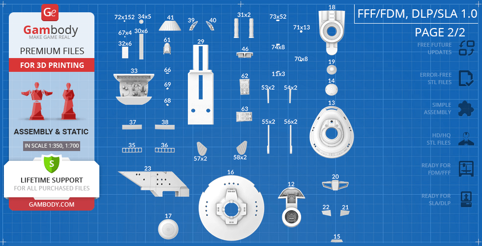
Alternative parts to build USS Enterprise NCC-1701 Refit. The corresponding numbers shall be swapped in the 1.0 Initial version.
Additional details
Part of diorama
No
Special pack included
No
You will get instant access to the STL files of USS Enterprise NCC-1701-A 3D Printing Model | Assembly after completing your purchase. Simply add the model to your cart and check out using PayPal, credit or debit card, Apple Pay, Google Pay, Alipay, or other available payment methods.
Watch the assembly video for USS Enterprise NCC-1701-A 3D Printing Model | Assembly, and explore more tutorials, behind-the-scenes content, 3D printing timelapses, and painting guides on the official Gambody YouTube channel.
This 3D model of USS Enterprise NCC-1701-A consists of files in StereoLithography (.Stl) format that is optimized for 3D printing.
Before printing the files, we strongly recommend reading the PRINTING DETAILS section.
WHAT WILL YOU GET AFTER PURCHASE?
- 4 versions of USS Enterprise NCC-1701-A STL files for FFF/FDM and DLP/SLA - files for all versions are available for download after the purchase;
- STL files of high-poly USS Enterprise NCC-1701-A model for 3D printing consist of 200 files;
- Sizes for:
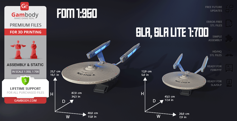
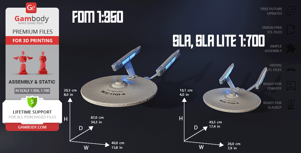
- FFF/FDM: 203 mm tall, 400 mm wide, 870 mm deep;
- FFF/FDM on the platform: 257 mm tall, 400 mm wide, 870 mm deep;
- DLP/SLA/Lite: 101 mm tall, 200 mm wide, 435 mm deep;
- DLP/SLA/Lite on the platform: 129 mm tall, 200 mm wide, 435 mm deep;
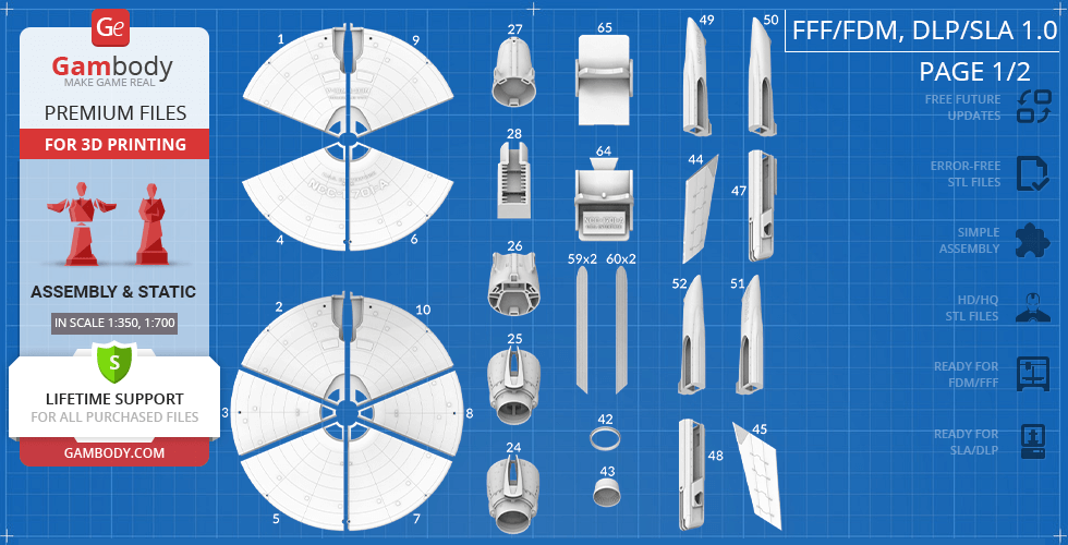
- Assembly Manual for FFF/FDM 1.0, DLP/SLA 1.0 and DLP/SLA Lite 1.0 versions in PDF and video formats;
- Detailed settings that we provide as a recommendation for Cura, Simplify3D, Slic3r and PrusaSlicer for the best print;
- Full technical support from the Gambody Support Team.
Detailed information about this 3D printing model is available in the DESCRIPTION section.
Before printing, take a look at Printing Details for recommended settings and tips to achieve better results.
ABOUT THIS 3D MODEL
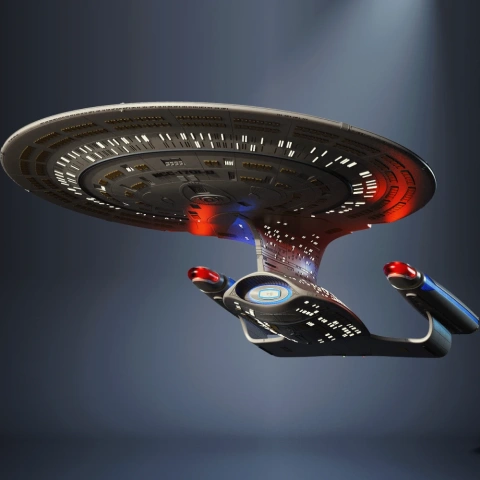
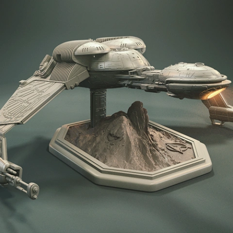
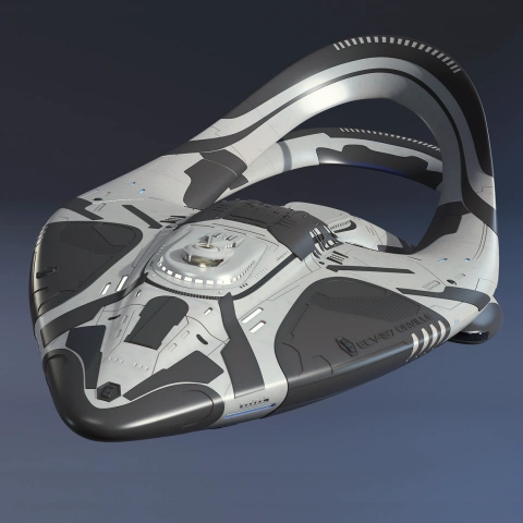
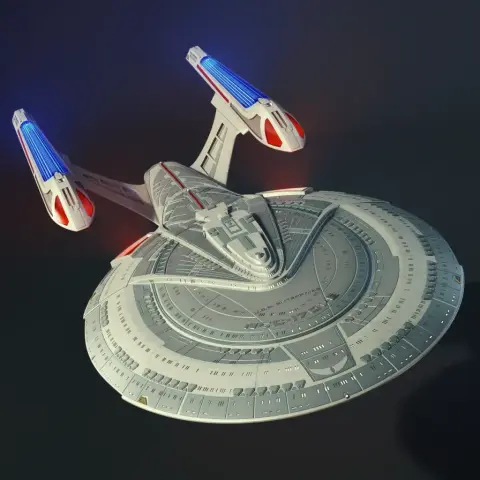
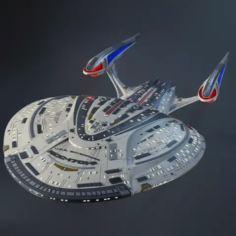
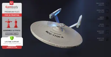
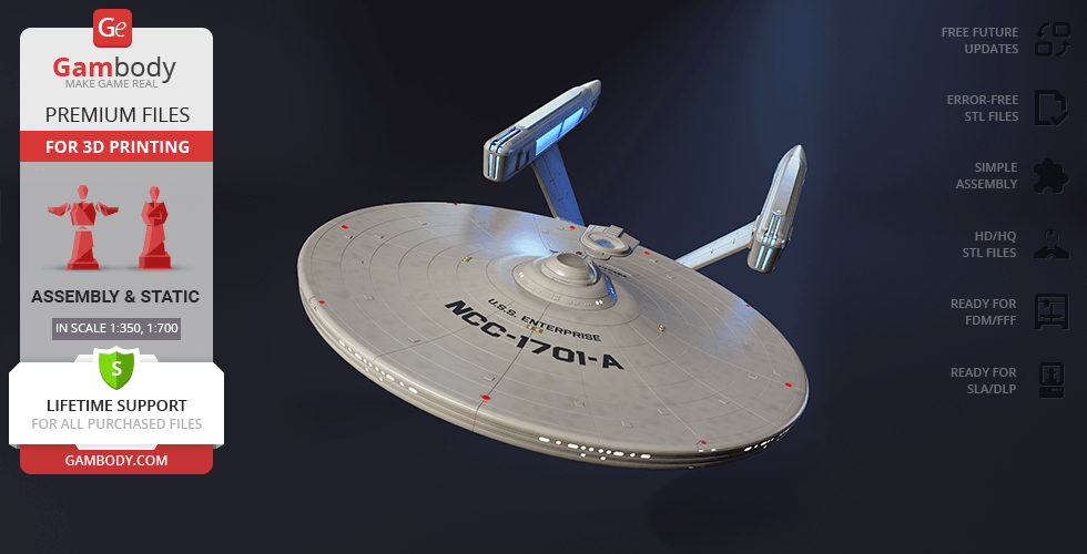
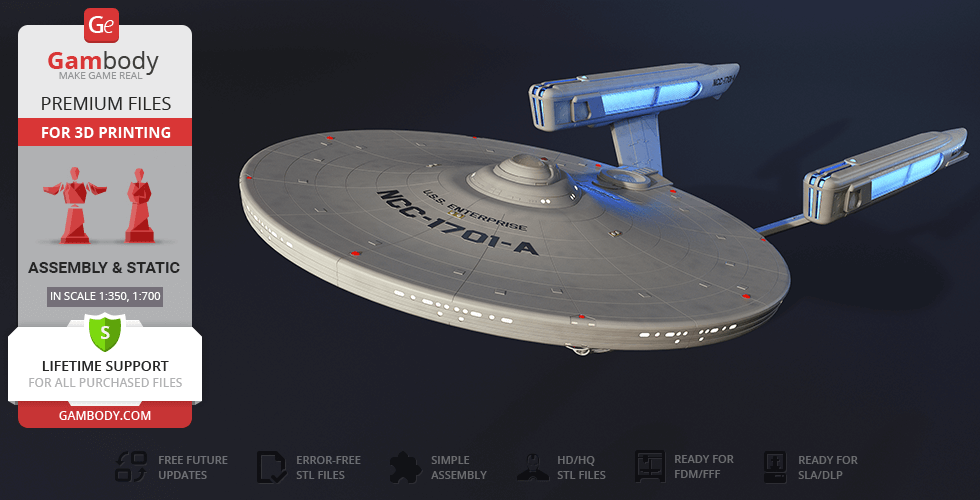
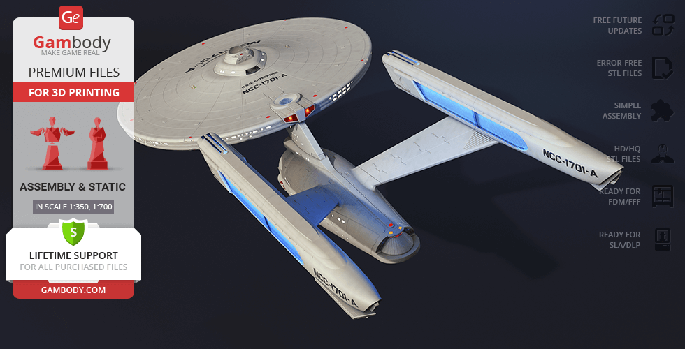
The science-fiction franchise Star Trek has proved to be one of the most outstanding television series in science-fiction television history and has a large influence on popular culture to this day. The story of the crew of the iconic spaceship Enterprise that defends the United Federation of Planets fascinates everyone who watches it, it doesn't matter for the first or the hundredth time. The tactical command cruiser Enterprise is used by captain James T. Kirk and his senior staff for the exploration of space and seeking out new life and new civilizations. After the self-destruction of the original Enterprise (NCC-1701) in Star Trek III: The Search for Spock, Captain Kirk is assigned to command a new USS Enterprise, NCC-1701-A.
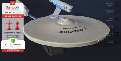
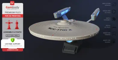
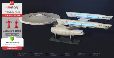
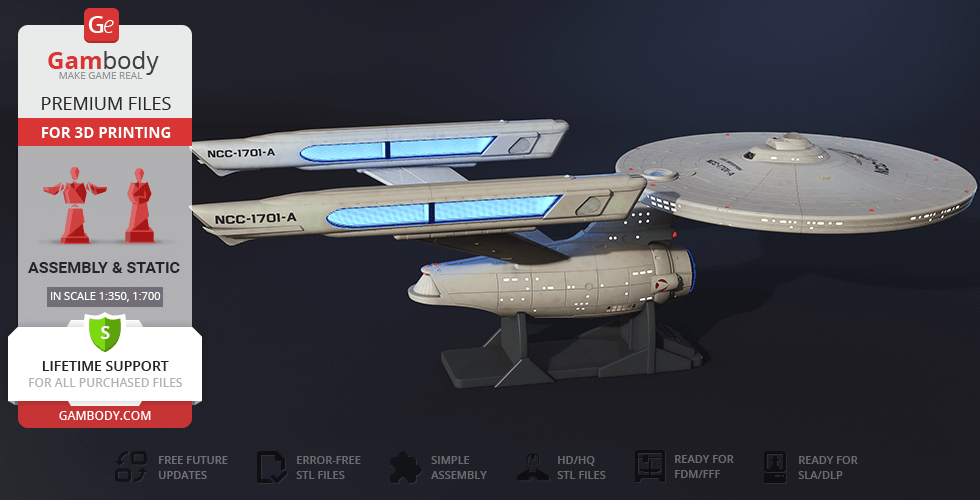
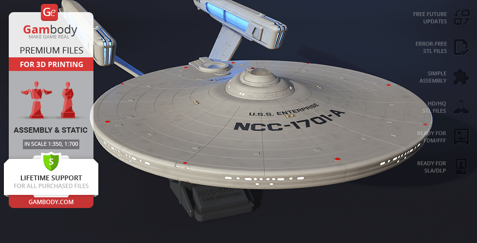
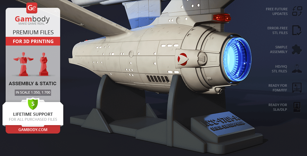
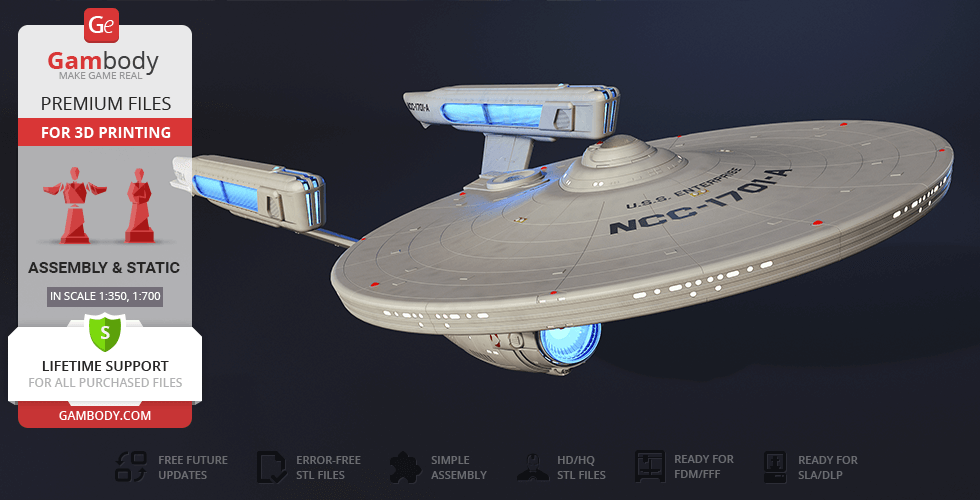
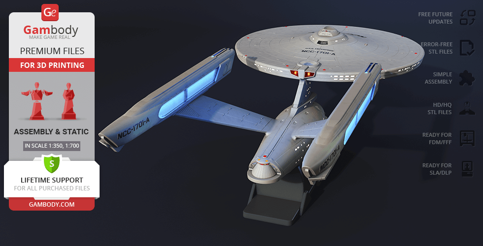
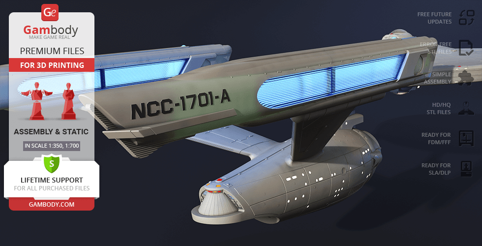
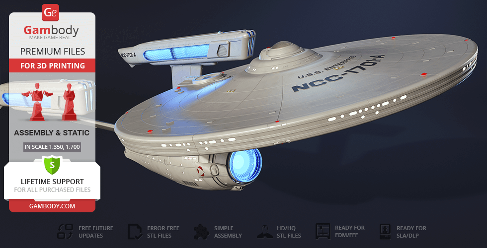
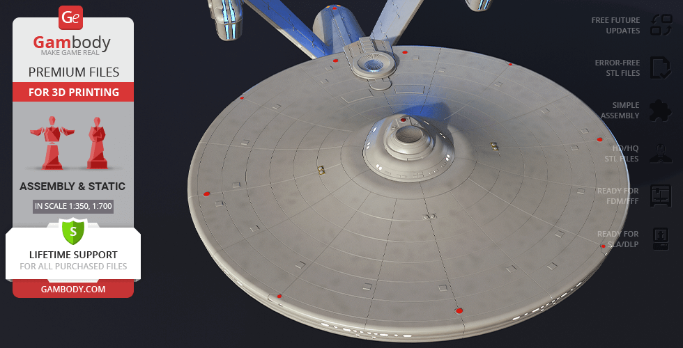
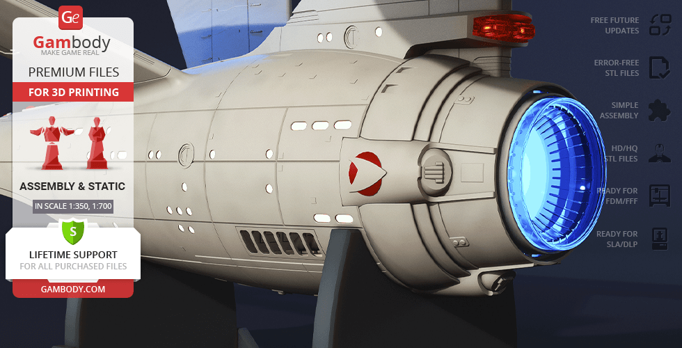
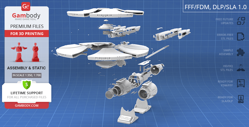
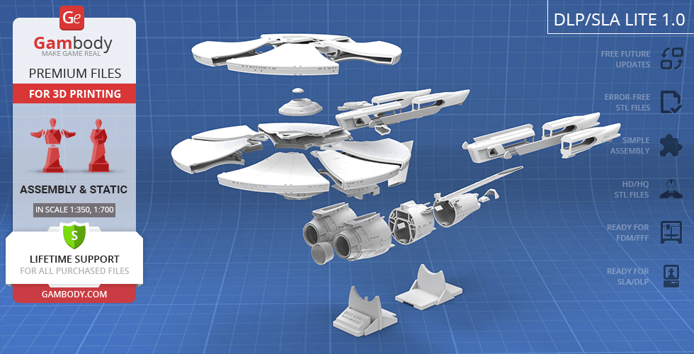
The author of the NCC-1701-A model for 3D printing decided to go for the original appearance of the iconic cruiser and while working on the project was drawing inspiration specifically from the unique design of the starship that now has a legendary status. The model consists of a saucer-shaped primary hull, a cylindrical secondary hull, and two engine nacelles. For the convenience of those who are only starting their 3D-printing journey, there is an alternative DLP/SLA Lite version with a smaller number of parts to ease the process of assembly. Moreover, it is possible to print the model using a multi-color production method. You can discover these and many more exciting features by purchasing the incredibly beautiful and highly detailed USS Enterprise NCC-1701-A!
ADAPTATION FOR 3D PRINTING
The USS Enterprise NCC-1701-A model for 3D printing is a static assembly model and its moderation and adaptation for different types of 3D printers took the Gambody team 96 hours in total.
For you to receive the cleanest 3D printing result possible, minimize the amount of filament needed for generated support, and make use of the active elements designed by Gambody Engineers, the cruiser was divided into convenient assembly parts.
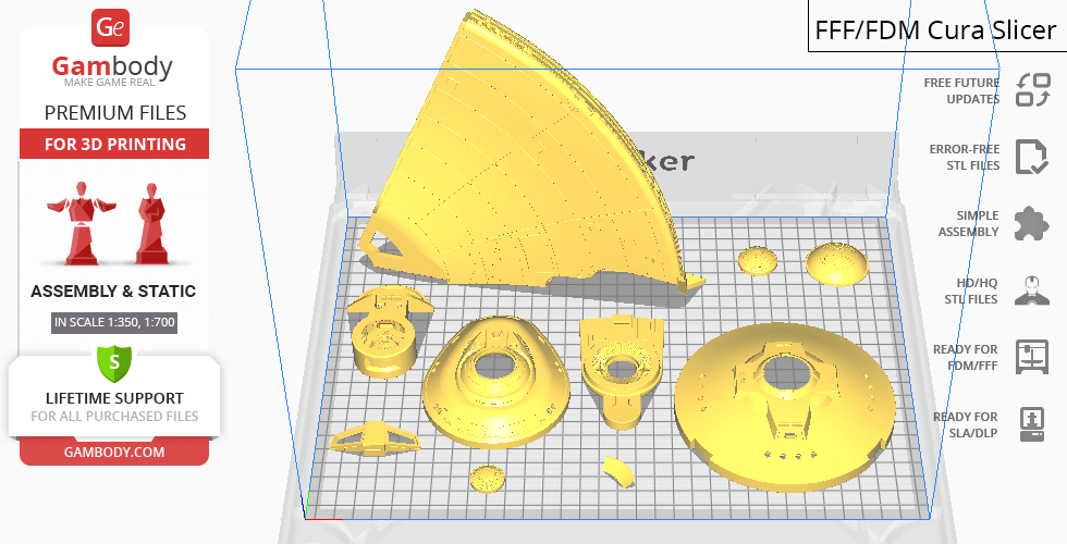
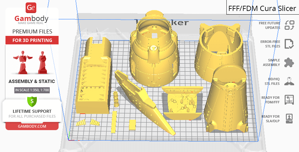
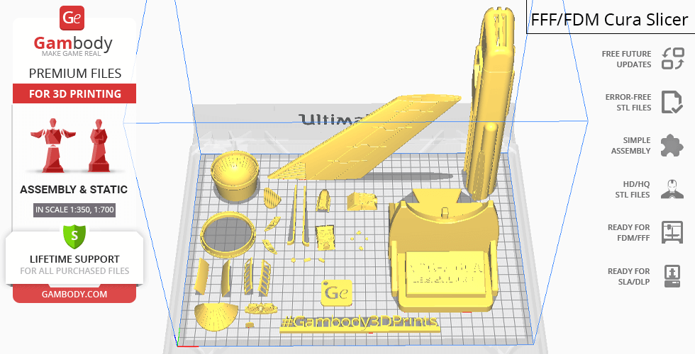
All assembly parts in the FFF/FDM 1.0 version are provided in STL files in recommended positions that were worked out in order to ensure the smoothness of the details’ surfaces after printing and that the 3D printing beginners won’t face difficulties when placing the parts on a build plate. When downloading any model’s file you will also receive “Assembly Manual” for FFF/FDM/DLP/SLA 1.0 and DLP/SLA Lite 1.0 versions in PDF and video formats. We highly recommend that you get acquainted with the “Assembly Video” and “Assembly Manual” before getting down to the USS Enterprise NCC-1701-A 3D printing model.
The model is saved in STL files, a format supported by most 3D printers. All STL files for 3D printing have been checked in Netfabb and no errors were shown.
The model’s scale was calculated from the length of the starship. The 3D printing model’s chosen scales are 1:350 for the FFF/FDM version and 1:700 for the DLP/SLA and DLP/SLA Lite versions.
VERSIONS’ SPECIFICATIONS
FFF/FDM 1.0 version features:
- Contains 80 parts;
- A printed model is 203 mm tall, 400 mm wide, 870 mm deep;
- A printed model on the platform is 257 mm tall, 400 mm wide, 870 mm deep;
- Two options for the garden windows - solid and with a frame;
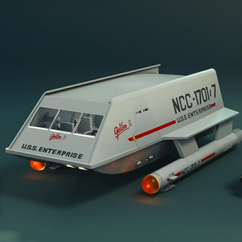
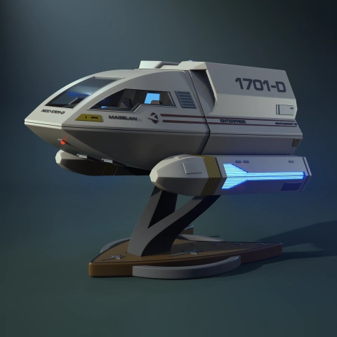
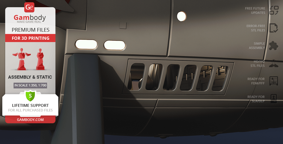
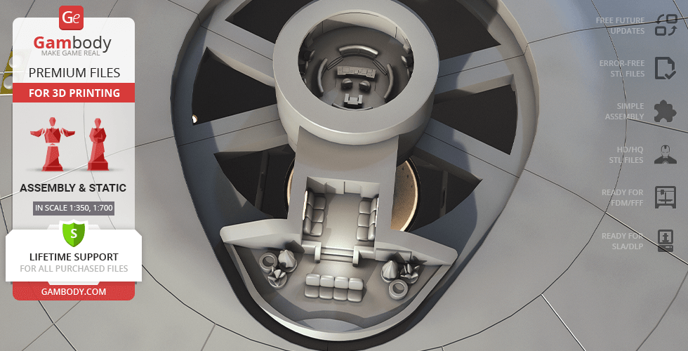
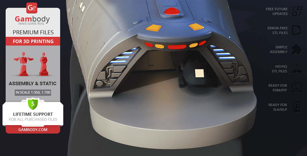
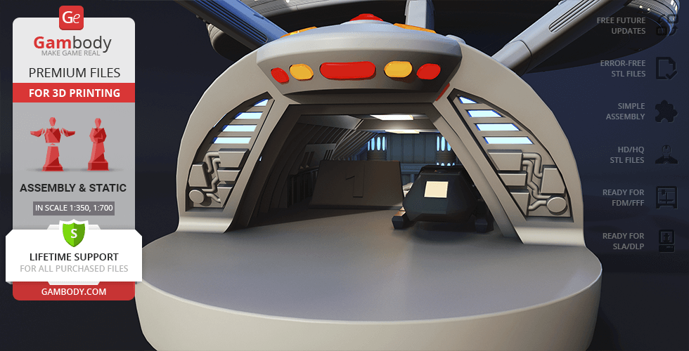
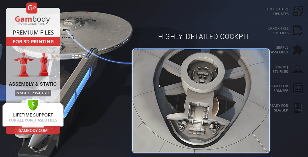
- Highly-detailed cockpit;
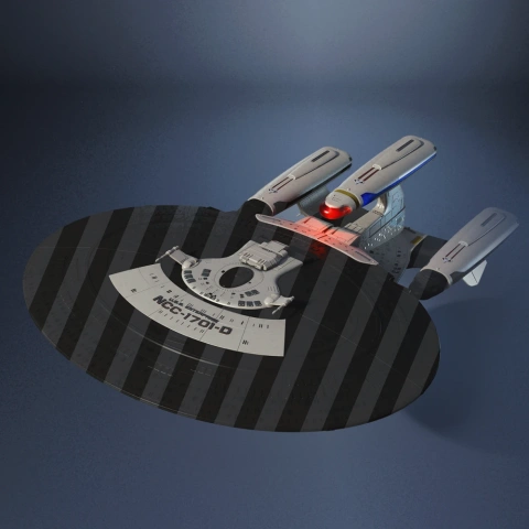
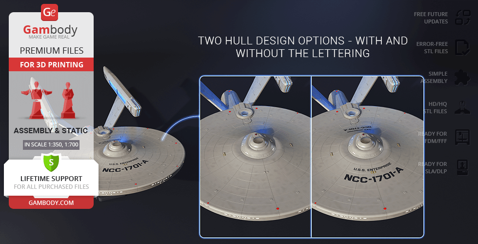
- Two hull design options - with and without the lettering;
- Two secondary hull variants - with and without a cutout for the platform;
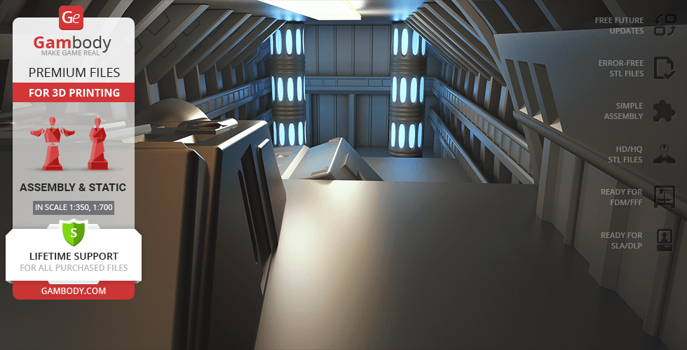
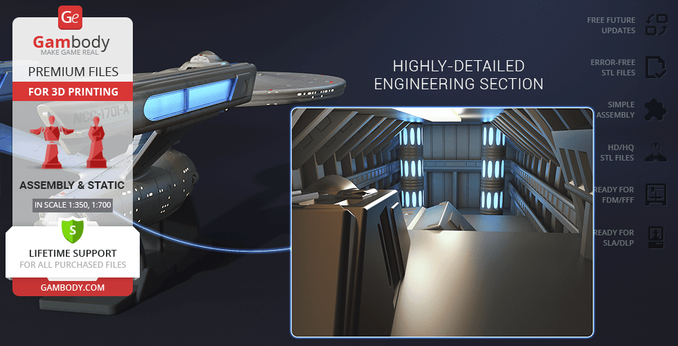
- Highly-detailed engineering section;
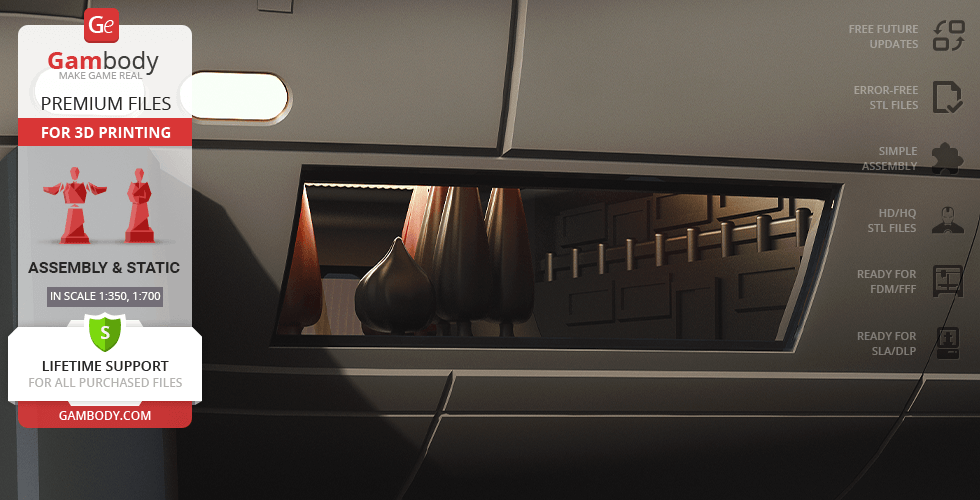
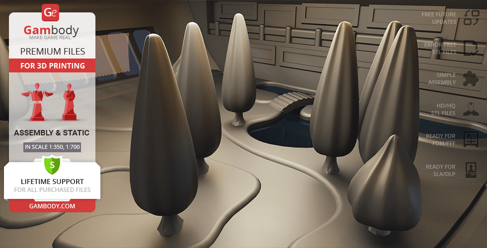
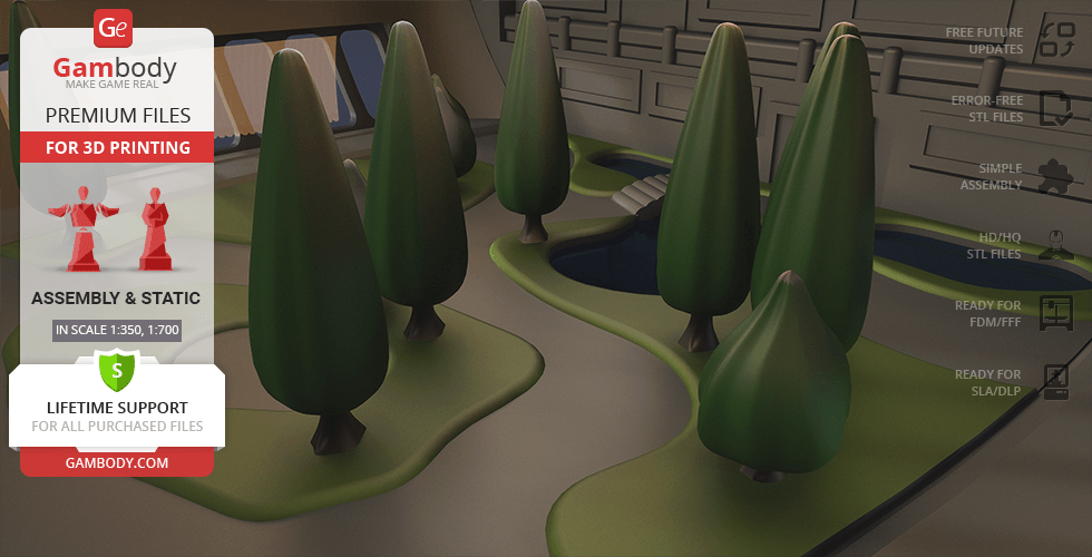
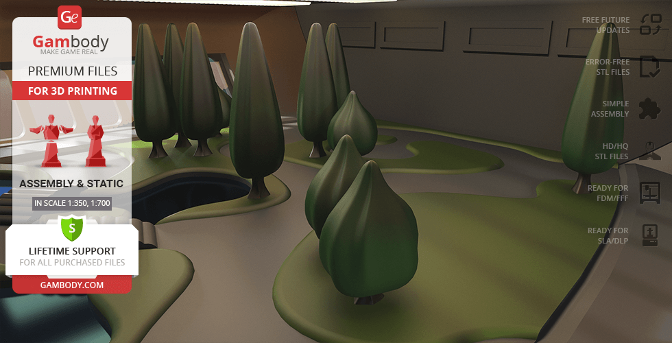
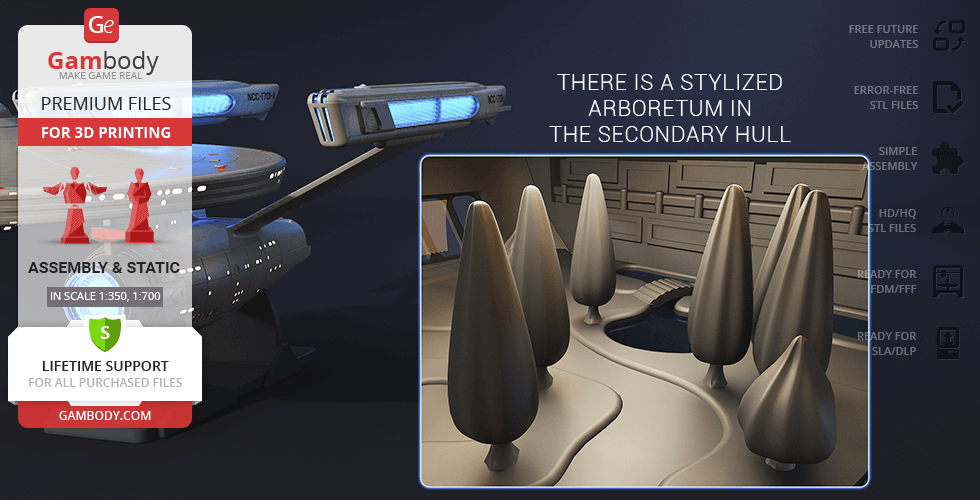
- There is a stylized arboretum in the secondary hull;
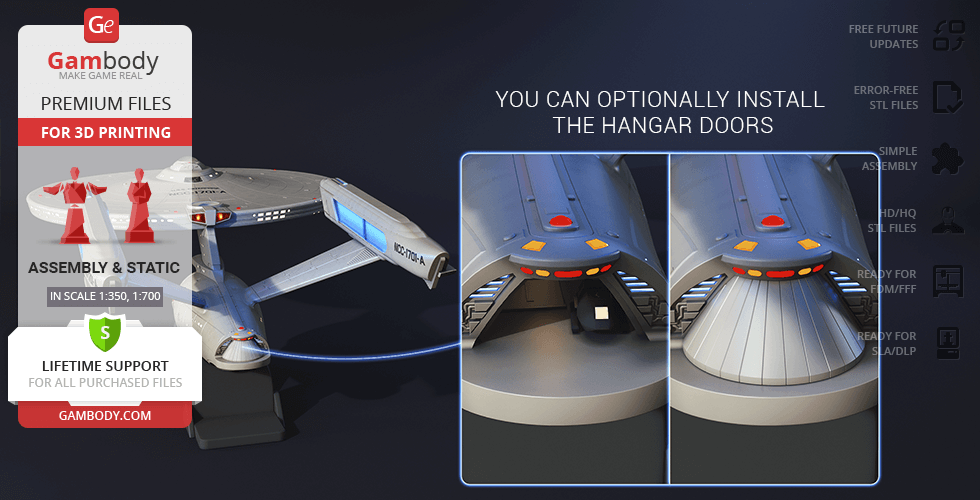
- You can optionally install the hangar doors;
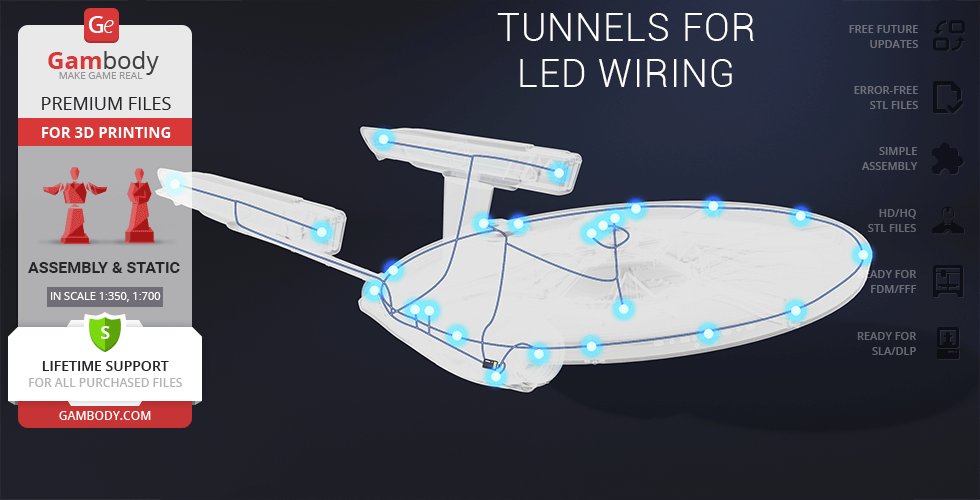
- Tunnels for LED wiring to install the lights (compatible with the lighting kit for polar lights);
- There are files for the platform;
- It is recommended to print the cockpit, the shuttles and the windows using a resin 3D printer for a greater level of detail;
- Alternative nacelles split in two;
- All parts are divided in such a way that you will print them with the smallest number of support structures.
DLP/SLA 1.0 version features:
- Contains 74 parts;
- A printed model is 101 mm tall, 200 mm wide, 435 mm deep;
- A printed model on the platform is 129 mm tall, 200 mm wide, 435 mm deep;
- Two options for the garden windows - solid and with a frame;
- Highly-detailed cockpit;
- Two hull design options - with and without the lettering;
- Two secondary hull variants - with and without a cutout for the platform;
- Highly-detailed engineering section;
- There is a stylized arboretum in the secondary hull;
- You can optionally install the hangar doors;
- Tunnels for LED wiring to install the lights (compatible with the lighting kit for polar lights);
- There are files for the platform;
- All parts are divided in such a way to fit the build plates and to ensure that support structures are generated where needed.
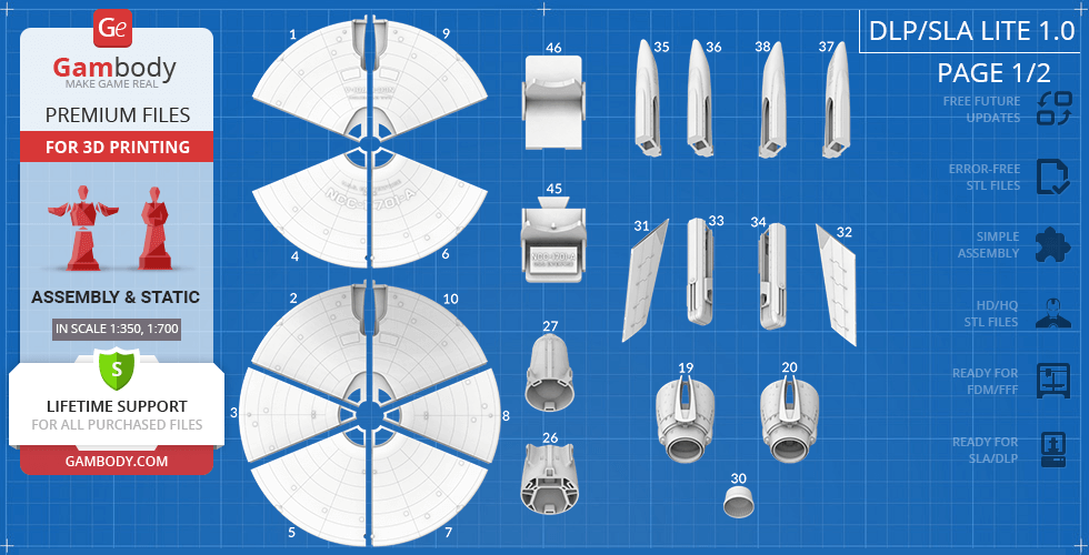
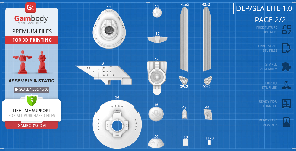
DLP/SLA Lite 1.0 version features:
- Contains 46 parts;
- A printed model is 101 mm tall, 200 mm wide, 435 mm deep;
- A printed model on the platform is 129 mm tall, 200 mm wide, 435 mm deep;
- Simplified assembly;
- All parts are divided in such a way to fit the build plates and to ensure that support structures are generated where needed.
You can get the USS Enterprise NCC-1701-A model for 3D printing immediately after the purchase! Just click the green Buy button in the top-right corner of the model’s page. You can pay with PayPal or your credit card.
Watch the tutorial on how to assemble a USS Enterprise NCC-1701-A 3D Printing Model onGambody YouTube channel.
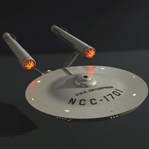
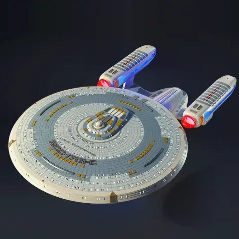
Also, you may like the USS Enterprise NCC-1701 3D Printing Model and other Star Trek 3D Printing Models.
________
FAQ:
Average customer rating (13 reviews)
4.5
Ratings breakdown
Click a star rating to filter reviews
Overall experience
Level of detail in the model
4.7
Model cut quality and assembly guide
4.4
Clarity and accuracy of the model page
4.3
Level of detail in the model
3.7
Model cut quality and assembly guide
2
Clarity and accuracy of the model page
2.2
I'm having difficulty identifying what is a support structure that requires removal and what is part of the model. Can you share some tips on how to differentiate a support structure from a model feature.
At the same time, we’d truly appreciate it if you could share a bit more about what didn’t fully meet your expectations during the process, as your overall rating and individual scores seem lower than the experience you described. Your insight would help us better understand where improvements may be needed.
Here are a few tips that can help you tell support structures apart from actual model features:
1. Review the assembly manual and preview images:
The assembly guide and product images show the final shape of each part. If an element does not appear in the finished model, it is most likely a support structure.
2. Check the STL file in your slicer:
When you load a part into your slicer, supports are usually generated automatically and displayed in a different color or pattern. This makes it easier to identify which elements are meant to be removed after printing.
For example, in Bambu Studio, you can set the Color Scheme to “Line Type”, which helps clearly distinguish model geometry from support structures (as shown in the image below).
3. Look at contact points (especially for Tree supports):
Supports typically connect to the model at small, thin contact points and are designed to break away cleanly. Functional or decorative model parts will be more solid and structurally integrated.
4. Use orientation clues:
Supports are most often found under overhangs, bridges, or steep angles where the printer needs temporary support. Flat surfaces and detailed features that match the final design are usually part of the model.
5. Test gently before removing:
If you’re unsure, apply very light pressure. Supports tend to snap off easily, while actual model parts will feel much sturdier.
If you’re ever in doubt, we recommend leaving a questionable element in place until you’ve double-checked the instructions or reached out for guidance.
If you have any other questions as you continue your build, please feel free to contact us anytime — we’re always happy to help and wish you a smooth and enjoyable continuation of your project!
Level of detail in the model
3.6
Model cut quality and assembly guide
3.6
Clarity and accuracy of the model page
1.5
There is nothing in the files that tell you which ones are the 1:350 aspect ration and which are other aspect ratios.
I'll check back in a few days to see if I get a reply.
First, please ensure that you’re using all parts from the FFF/FDM version of the model only. To do so, select and download the folder corresponding to the FFF/FDM printer type, where all parts are uniformly scaled to 1:350. You won’t need any other parts for the assembly.
Please also note that there are two options for the saucer parts:
-With lettering – parts #1, 4, 6, and 9
-Without lettering – parts #2, 3, 5, 7, 8, and 10
Make sure to use parts from the same option to avoid assembly mismatches or doubling. The PDF assembly guide included with the files or the Video guide can help to assemble the pieces together.
https://www.youtube.com/watch?v=fM__-DqMVmk
If the issue persists, please let us know the exact file names you’re having trouble with to align, and we’ll investigate further to ensure your assembly goes smoothly. Thank you for your patience and cooperation!
Level of detail in the model
4.7
Model cut quality and assembly guide
2.3
Clarity and accuracy of the model page
2.8
We noticed your comment that the saucer "needs a lot of filling". The need for additional filling may sometimes occur due to slight misalignments between printed parts, which can depend on printer calibration, slicing settings, or assembly precision. To help us understand this better, please contact us at support@gambody.com and provide more details about your print—including the 3D printer and slicer you used, your printing settings, and, if possible, a few photos of the areas that required filling. Our Moderation Team will be happy to analyze your case and provide tailored recommendations or check the files if necessary.
We look forward to hearing from you!
Level of detail in the model
5
Model cut quality and assembly guide
5
Clarity and accuracy of the model page
5
Level of detail in the model
5
Model cut quality and assembly guide
5
Clarity and accuracy of the model page
5
Level of detail in the model
4
Model cut quality and assembly guide
4
Clarity and accuracy of the model page
4
Level of detail in the model
5
Model cut quality and assembly guide
5
Clarity and accuracy of the model page
5
Level of detail in the model
5
Model cut quality and assembly guide
5
Clarity and accuracy of the model page
5
Level of detail in the model
5
Model cut quality and assembly guide
5
Clarity and accuracy of the model page
5
Level of detail in the model
5
Model cut quality and assembly guide
5
Clarity and accuracy of the model page
5
Level of detail in the model
5
Model cut quality and assembly guide
5
Clarity and accuracy of the model page
5
Level of detail in the model
5
Model cut quality and assembly guide
5
Clarity and accuracy of the model page
5
Level of detail in the model
5
Model cut quality and assembly guide
5
Clarity and accuracy of the model page
5
Below you'll find detailed slicing settings for Bambu Studio 2.0+, Orca Slicer 2.0+, UltiMaker Cura 5.0+, PrusaSlicer 2.0+, Slic3r 1.3+, Simplify3D 5.0+ to help you get the best results when printing this model. These settings are optimized specifically for this 3D model, but please note they may need slight adjustments depending on your printer or filament. When in doubt, refer to your printer's user manual.
To avoid printing issues and achieve the best quality, we highly recommend applying the following settings:
For better quality use 0.12 mm layer height, for fast printing use 0.2 mm layer height. For pins and the Ge connectors, use 0.2 layer height.
120-150% of your Layer Height
But you can paint the seam if you want.
You have to calibrate this parameter
You have to calibrate this parameter
You have to calibrate this parameter
For pins and power elements of the structure, such as the vehicle frame, use 3 loop
Disabled for vehicles and enabled for characters
For 0,2 Layer Height
The parameters in this tab vary greatly, it all depends on the quality of your printer. For example, if you have a classic Ender3, stick to the minimum parameters, but if you have a newer printer, for example Anycubic cobra 3 v2, you can select the maximum recommended values
Settings for advanced users, change these parameters only if you have sufficient 3D printing expertise
Enable this parameter if your model requires supports
We also recommend placing and removing supports manually in some places using special button
1-2 loops for more thick support
Top Z distance = 1-1.3 layer Height. If the supports are hard to remove, try increasing this setting by 0.1-0,4 mm
Bottom Z distance = 1-1.3 layer Height. If the supports are hard to remove, try increasing this setting by 0.1-0,4 mm
You have to calibrate this parameter which one is better for your filament
Increase this parameter if the supports are hard to remove from walls
For PLA and PETG filament types
5-8 mm is optional for small prints that have bad adhesion to the build plate
You have to calibrate this parameter
Read the description on your filament roll
Read the description on your filament roll and increase this parameter for fast printers
Read the description on your filament roll and increase this parameter for fast printers
For better quality use 0.12 mm layer height, for fast printing use 0.2 mm layer height. For pins and the Ge connectors, use 0.2 layer height.
120-150% of your Layer Height
But you can paint the seam if you want.
0.01-0.05 You have to calibrate this parameter
0.01-0.05 You have to calibrate this parameter
0.1-0.2 You have to calibrate this parameter
For pins and power elements of the structure, such as the vehicle frame, use 3 loop
Disabled for vehicles and ships, enabled for characters
For 0,2 Layer Height
For 0,2 Layer Height
The parameters in this tab vary greatly, it all depends on the quality of your printer. For example, if you have a classic Ender3, stick to the minimum parameters, but if you have a newer printer, for example, Anycubic Kobra 3 Or Bambulab A1, you can select the maximum recommended values.
Settings for advanced users, change these parameters only if you have sufficient 3D printing expertise
Enable this parameter if your model requires supports
We also recommend placing and removing supports manually in some places using special button
Top Z distance = 1-1.3 layer Height. If the supports are hard to remove, try increasing this setting by 0.1-0,4 mm
Bottom Z distance = 1-1.3 layer Height. If the supports are hard to remove, try increasing this setting by 0.1-0,4 mm
Increase this parameter if the supports are hard to remove from walls
For PLA and PETG filament types
5-8 mm is optional for small prints that have bad adhesion to the build plate
Read the description on your filament roll
Read the description on your filament roll and increase this parameter for fast printers
You have to calibrate this parameter
Read the description on your filament roll and increase this parameter for fast printers
Read the description on your filament roll
This field is filled in according to your printer specifications when you add it to the slicer.
You can add custom G-code here for the start and end of the print. However, be careful - this is for advanced users only!
You have to calibrate your printer using Ge retraction test models
Retraction Length: For direct-drive setups use 0.5 mm to 2.5 mm; for Bowden extruders use 5 to 7 mm
This is how fast the filament is pulled back—40-60 mm/s for direct drive and 30-50 mm/s for Bowden setups.
You have to calibrate this parameter: Reduce it until the printer starts to hit the parts with the nozzle during printing, then increase it by 0.2.
For better quality use 0.12 mm layer height, for fast printing use 0.2 mm layer height. For pins and the Ge connectors, use 0.2 layer height.
120-150% of your Layer Height
To increase the strength of the print parts, use wall line count: 3
For pins and connectors use 50% Infill
These parameters are for standard PLA plastic. If you are using a different type of plastic, check the printing temperature recommended by the manufacturer. Also, read the description on your filament spool. For fast printers, add +30 °C to the current parameters.
The parameters in this tab vary greatly, it all depends on the quality of your printer. For example, if you have a classic Ender3, stick to the minimum parameters, but if you have a newer printer, for example Anycubic cobra 3 v3, you can select the maximum recommended values
Settings for advanced users, change these parameters only if you have sufficient 3D printing expertise.
You need to calibrate this parameter using Gambody test models. These values are average values for a Direct Drive extruder; for a Bowden extruder, the values should be increased.
You need to calibrate this parameter using Gambody test models. These values are average values for a Direct Drive extruder; for a Bowden extruder, the values should be increased.
Use this value other than 0 if your nozzle catches on the internal infill during travel moves. Try to keep this value as low as possible in height.
Use normal supports to support large, straight surfaces (most mechanical or technical parts).
You have to calibrate this parameter according to the capabilities of your printer and your filament, using a Gambody test models.
Use 1 instead of 0 if your supports are thin and tall. They will be harder to remove, but much stronger.
Top Z distance = 1-1.3 layer Height. If the supports are hard to remove, try increasing this setting by 0.1-0,4 mm
Increase this parameter if the supports are hard to remove from walls
Use tree supports to support complex objects, such as characters.
You have to calibrate this parameter according to the capabilities of your printer and your filament, using a Gambody test models.
Top Z distance = 1-1.3 layer Height. If the supports are hard to remove, try increasing this setting by 0.1-0,4 mm
Increase this parameter if the supports are hard to remove from walls
Use a skirt for all parts when printing on outdated printers.
Use a brim when printing thin but tall parts, as well as parts with a small bed adhesion area.
For better quality use 0.12 mm layer height, for fast printing use 0.2 mm layer height. For pins and the Ge connectors, use 0.2 layer height.
120-150% of your Layer Height
for 0.2 Layer Height
But you can paint the seam if you want.
(for PLA and PETG)
(5-8 mm is optional for small prints that have bad adhesion to the build plate)
Enable this parameter if your model requires supports
(45-50 degree)You have to calibrate this parameter according to the capabilities of your printer
and your filament, using a Gambody test models.
Top contact Z distance = 1-1.3 layer Height. If the supports are hard to remove, try
increasing this setting by 0.1-0,4 mm
Top contact Z distance = 1-1.3 layer Height. If the supports are hard to remove, try
increasing this setting by 0.1-0,4 mm
Increase this parameter if the supports are hard to remove from walls
The parameters in this tab vary greatly, it all depends on the quality of your printer. For example, if you have a classic Ender3, stick to the minimum parameters, but if you have a newer printer, for example Anycubic cobra 3 v3, you can select the maximum recommended values
Settings for advanced users, change these parameters only if you have sufficient 3D printing expertise. Use the minimum value for outdated printers without acceleration calibration, and the maximum value for modern printers if you need it.
These settings only work for 3D printers with multiple extruders
You can try setting all parameters in this section, except the First layer, to values between 0.75% of your nozzle diameter and 1.25% of your nozzle diameter. Adjusting them will help you work out the optimal parameters for the best quality for your print. As for the First layer, you can set it to 150% of the diameter of your nozzle for better adhesion to the build plate (for a nozzle with a diameter of 0.4 mm, the First layer extrusion width can be from 0.3 mm to 0.5 mm)
For better printing quality you have to calibrate this parameter using Gambody test model.
Check your filament manufacturer's temperature recommendations on the spool.
Cooling parameters depends on the material you use for printing.
*for PLA
For better quality use 0.12 mm layer height, for fast printing use 0.2 mm layer height. For pins and the Ge connectors, use 0.2 layer height.
120-150% of your Layer Height
For 0.12 Layer Height
For 0.12 Layer Height
For pins and connectors use 50% Infill
Use skirt for outdated 3d printers
(5-8 mm is optional for small prints that have bad adhesion to the build plate)
Enable this parameter if your model requires supports
(45-60 degree)You have to calibrate this parameter according to the capabilities of your printer and your filament, using a Gambody test models
Contact Z distance = 1-1.3 layer Height. If the supports are hard to remove, try increasing this setting by 0.1-0,4 mm
The parameters in this tab vary greatly, it all depends on the quality of your printer. For example, if you have a classic Ender3, stick to the minimum parameters, but if you have a newer printer, for example Anycubic cobra 3 v3, you can select the maximum recommended values
Settings for advanced users, change these parameters only if you have sufficient 3D printing expertise. Use the minimum value for outdated printers without acceleration calibration, and the maximum value for modern printers if you need it.
You have to calibrate this parameter from 0.9 to 1.1 according to the capabilities of your printer and your filament, using a Gambody test models.
Check your filament manufacturer's temperature recommendations on the spool.
Cooling parameters depends on the material you use for printing.
Calibrate this value if you need to reduce or improve the adhesion between the plastic and the heat bed
Your current nozzle diameter
You need to calibrate this parameter using Gambody test models. These values are average values for a Direct Drive extruder; for a Bowden extruder, the values should be increased.
Your current nozzle diameter
You have to calibrate this parameter using Gambody test models.
You need to calibrate this parameter using Gambody test models. These values are average values for a Direct Drive extruder; for a Bowden extruder, the values should be increased.
For better quality use 0.12 mm layer height, for fast printing use 0.2 mm layer height. For pins and the Ge connectors, use 0.2 layer height.
For 0,2 Layer Height
For 0,2 Layer Height
To increase the strength of the print parts, use Outline Perimeters: 3
You can enable this parameter to print rounded or spherical models, as well as character models.
Use this option only if your parts are too tight. but better calibrate your printer extrusion
Use this option only if your parts are too tight. but better calibrate your printer extrusion
Use 2 and more if you want to create skirt instead brim
1-2 for skirt and 10-20 for brim
Use for wipe nozzle if you need
Use For ABS filament
For pins and connectors use 50% Infill
Top Z distance = 1-1.3 layer Height. If the supports are hard to remove, try increasing this setting by 0.1-0,4 mm
Calibrate your filament and detect optimal temperature for it
Average temperature for PLA filament
The parameters in this tab vary greatly, it all depends on the quality of your printer. For example, if you have a classic Ender3, stick to the minimum parameters, but if you have a newer printer, for example Anycubic cobra 3 v3, you can select the maximum recommended values
Settings for advanced users, change these parameters only if you have sufficient 3D printing expertise.
FFF/FDM
Alternative parts to build USS Enterprise NCC-1701 Refit. The corresponding numbers shall be swapped in the 1.0 Initial version.