


Files
3D model format
Stereolithography (.stl)
Total files
Slicer settings
not available
Mesh error check
not specified
Support
Lifetime support from Gambody team
Update requests
not specified
Model versions
FFF/FDM
Assembly method
not specified
Features
DLP/SLA
Assembly method
not specified
Features
SLS
Assembly method
not specified
Features
DLP/SLA
Assembly method
not specified
Features
Additional details
Part of diorama
No
Special pack included
No
You will get instant access to the STL files of Rick & Morty Fight Scene in Diorama 3D Printer Files | Assembly after completing your purchase. Simply add the model to your cart and check out using PayPal, credit or debit card, Apple Pay, Google Pay, Alipay, or other available payment methods.
Watch the assembly video for Rick & Morty Fight Scene in Diorama 3D Printer Files | Assembly, and explore more tutorials, behind-the-scenes content, 3D printing timelapses, and painting guides on the official Gambody YouTube channel.
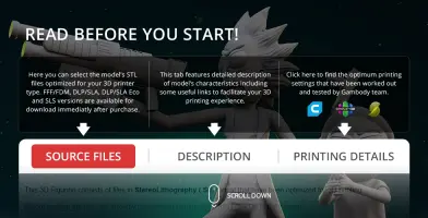
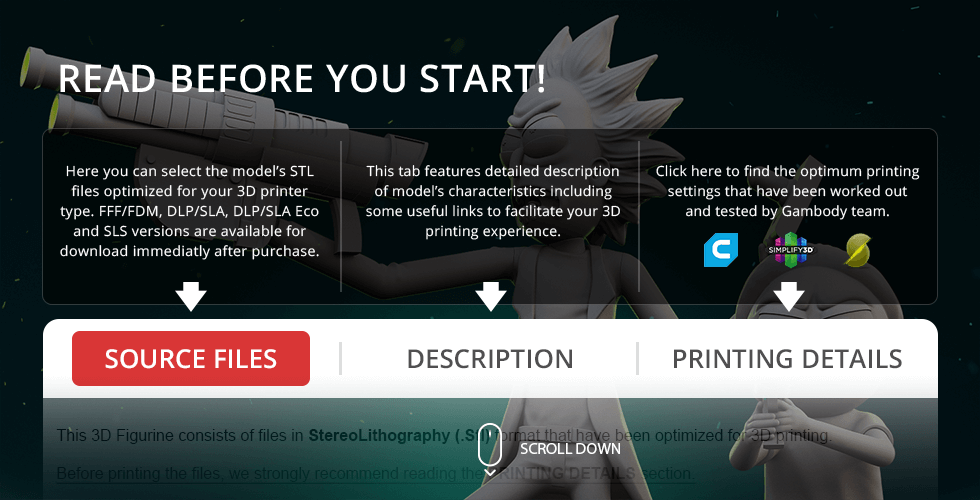
This 3D Diorama consists of files in StereoLithography (.Stl) format that is optimized for 3D printing.
Before printing the files, we strongly recommend reading the PRINTING DETAILS section.
Rick & Morty Fight Scene 3D Printing Figurines in Diorama come in 4 versions for each 3D printer type (FFF/FDM, DLP/SLA and SLS). Files for each version are available for download after the purchase.
Detailed information about this 3D printing diorama is available in the DESCRIPTION section.
Before printing, take a look at Printing Details for recommended settings and tips to achieve better results.
ABOUT THIS 3D MODEL
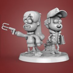
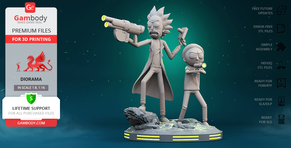
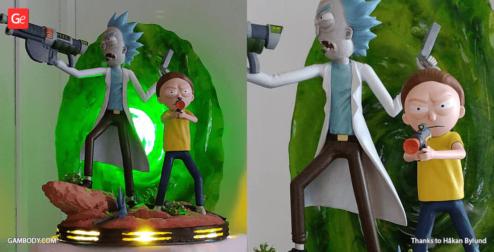
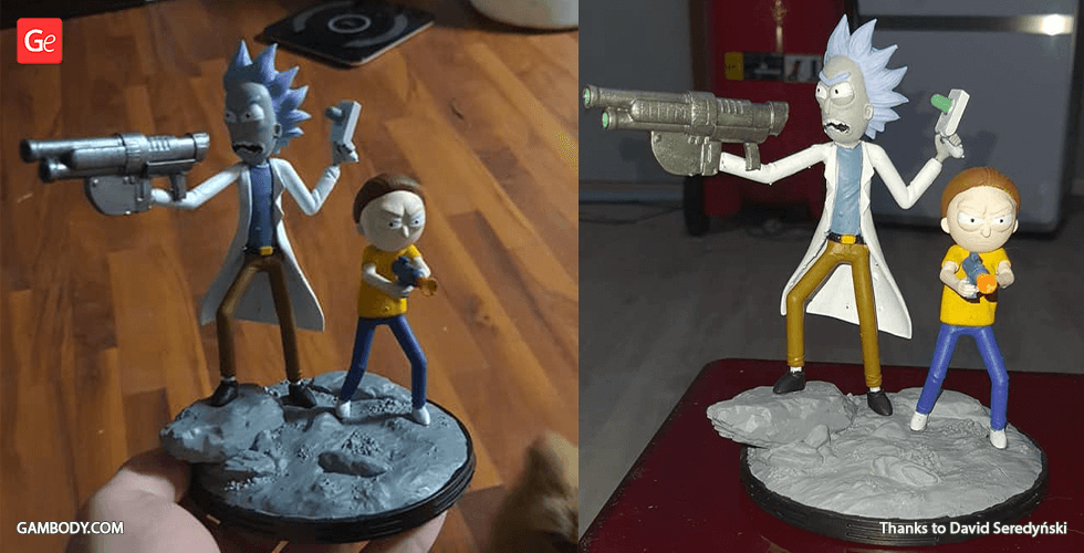
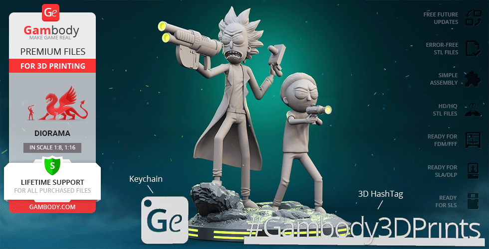
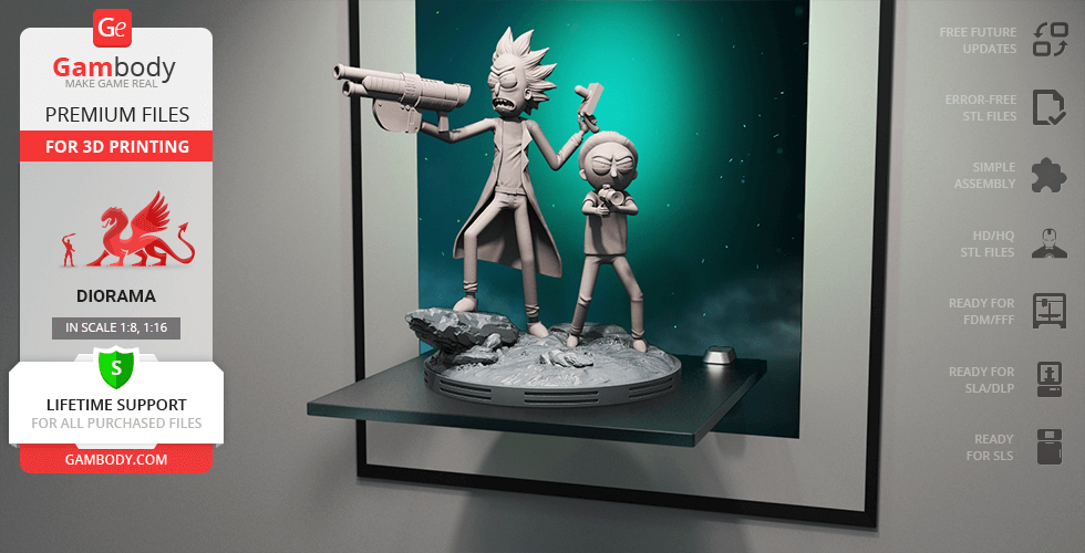
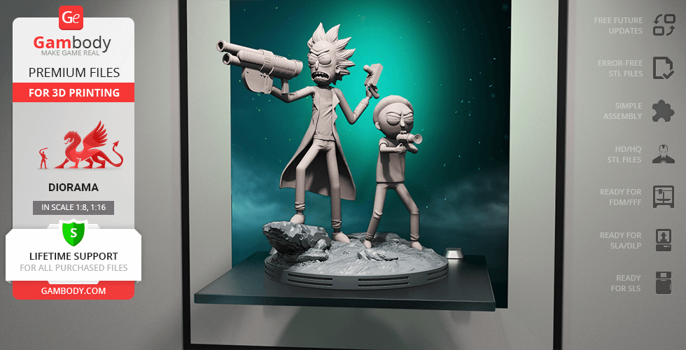
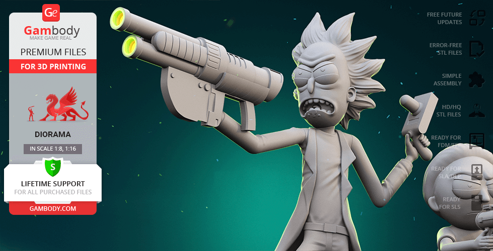
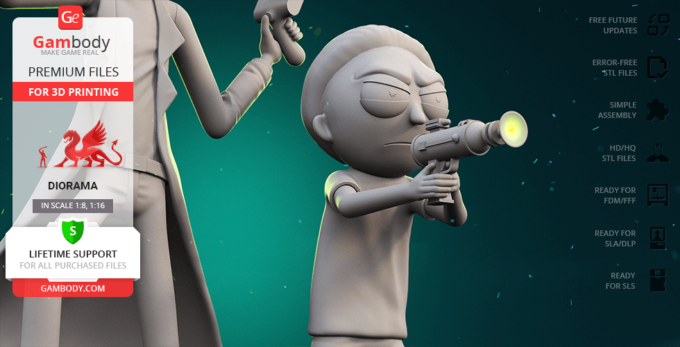
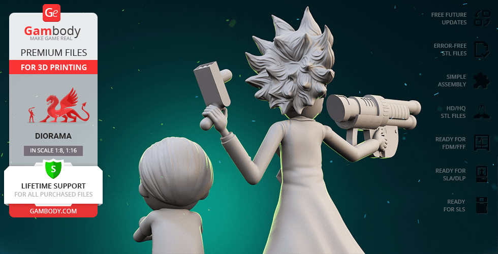
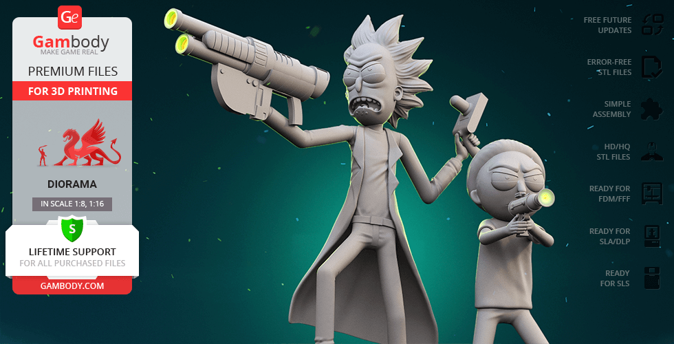
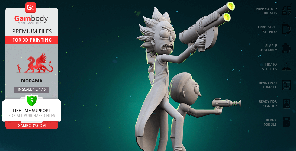
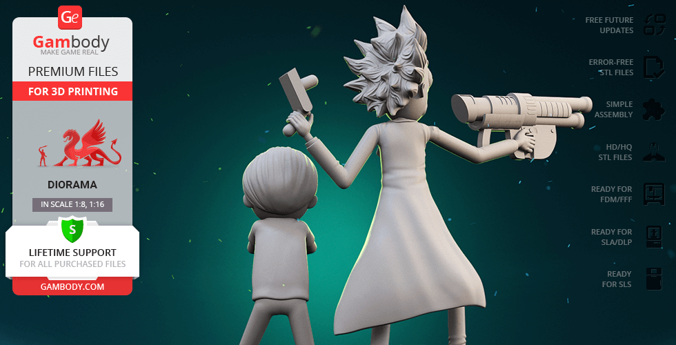
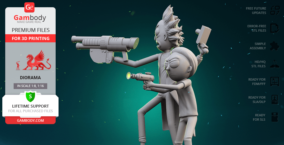
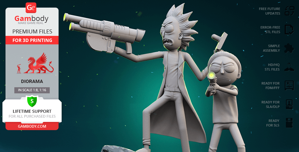
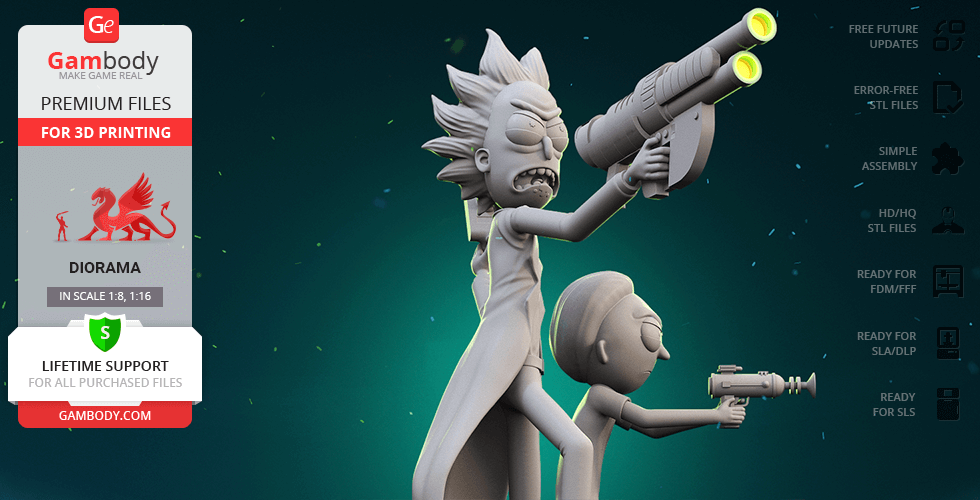
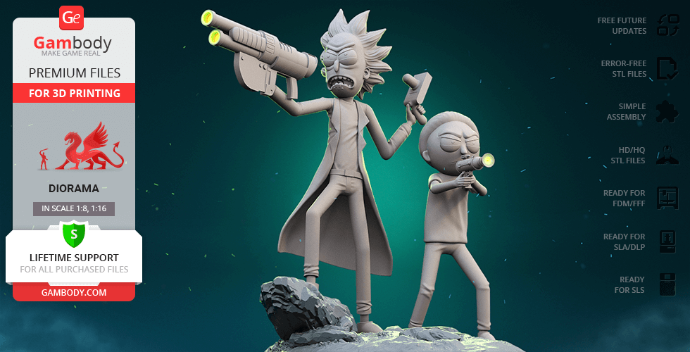
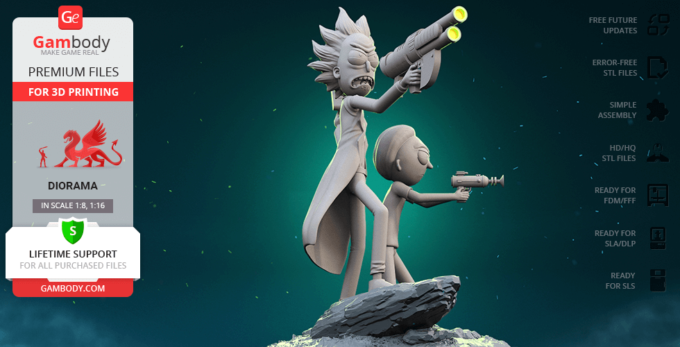
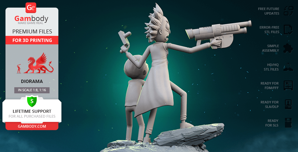
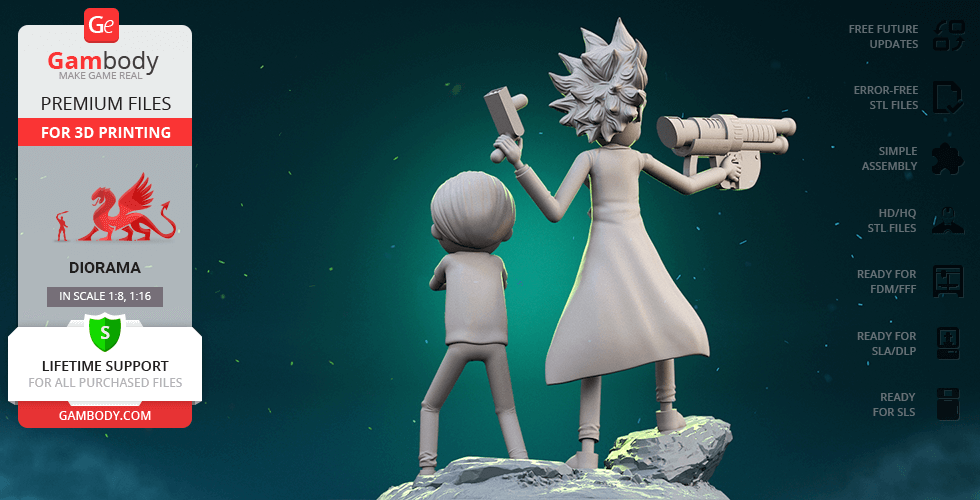
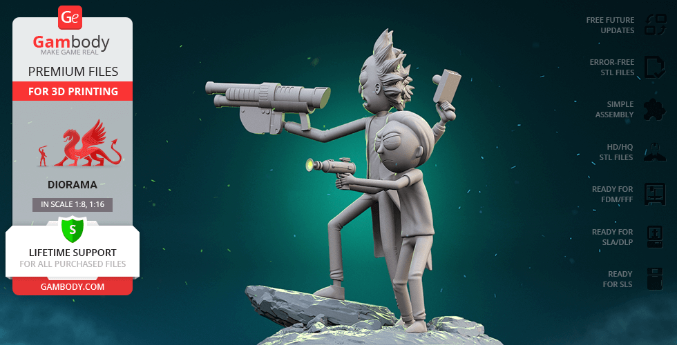
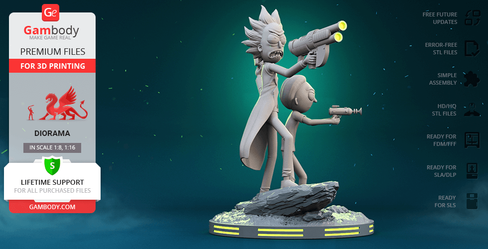
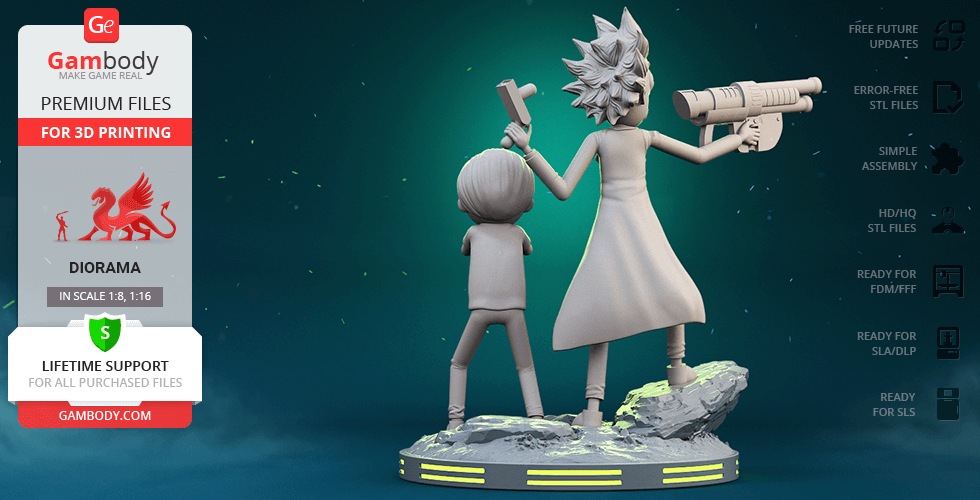
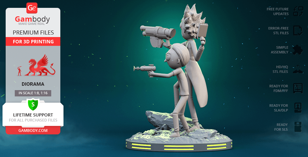
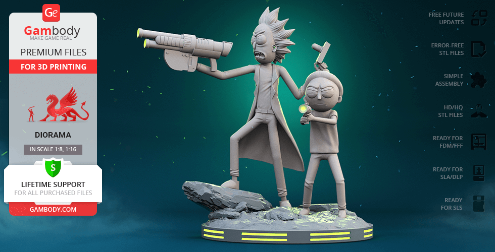
There is no denying that Rick and Morty TV show has been a roaring success since the moment its pilot aired and still remains a pop culture phenomenon. The insane adventures of the alcoholic super scientist Rick and his not-so-intelligent grandson Morty are being masterly crafted by the creators Dan Harmon and Justin Roiland episode by episode, coming up with always new and unique plots and memorable quotes. As many of the sitcom fans might have already guessed, the author of the Rick & Morty Fight Scene for 3D printing drew inspiration from the incredible and bizarre episode "Total Rickall” of the show’s second season. While the Smith household is terrorized by ridiculous alien parasites, the whole family needs to be on the lookout for fake relatives, Big Ducks with muscles, baby wizards, ghosts in the jars, reverse giraffes, etc. Thus, Rick Sanchez revealed his massive laser guns arsenal and distributed the awesome weapons between the non-parasitic members of the family. The 3D artist behind the diorama for 3D printing decided to depict the inseparable duo only and spent circa 175 hours portraying the characters armed to the teeth and ready to destroy the sly parasites. Both 3D printing figurines clearly look as if they were caught in the middle of the heated action. 3D printing Rick is clearly furious and has a double-barreled laser gun in his left hand plus Portal Gun in the right. He must be pretty displeased with the betrayal of the fake life-long friend Pencilvester! Morty figurine for 3D printing is wielding a smaller but obviously no less effective energy gun. The whole 3D printing action scene looks exceptionally dynamic and thanks to the original rocky platform provided by the author of the diorama, you may imagine the pair somewhere amid some interdimensional exploits! The incredible adventures of the crazy scientist and his grandson are presented via the well-loved masterpiece in the form of an animated series by Adult Swim. Now you’ve got a perfect opportunity to tame the wild duo by 3D printing the Rick & Morty Fight Scene!
ADAPTATION FOR 3D PRINTING
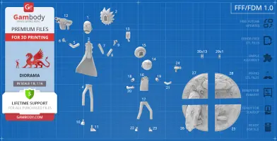
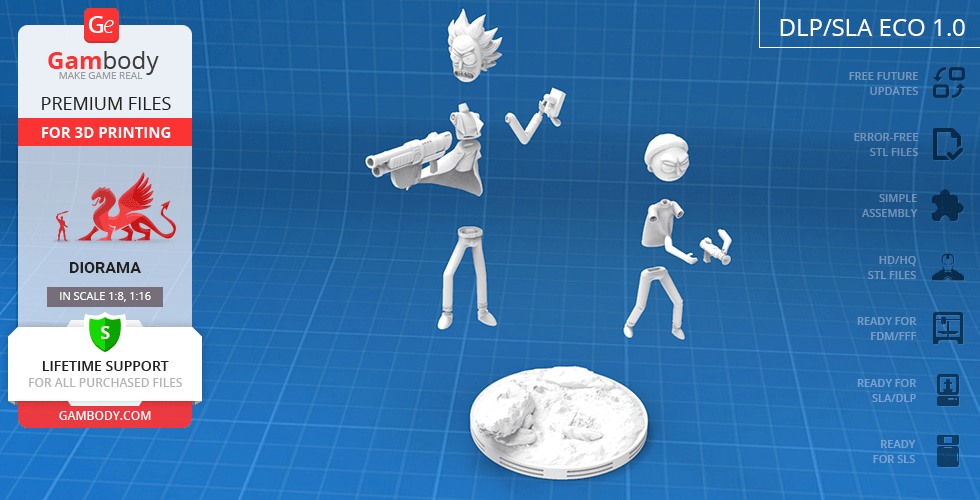
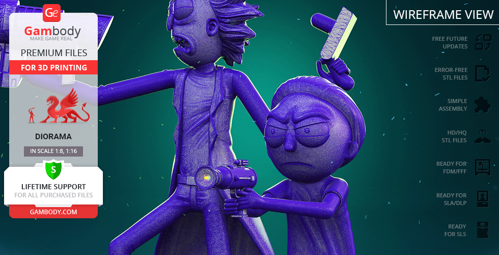
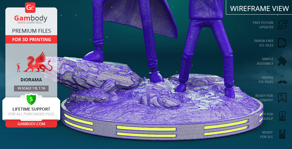
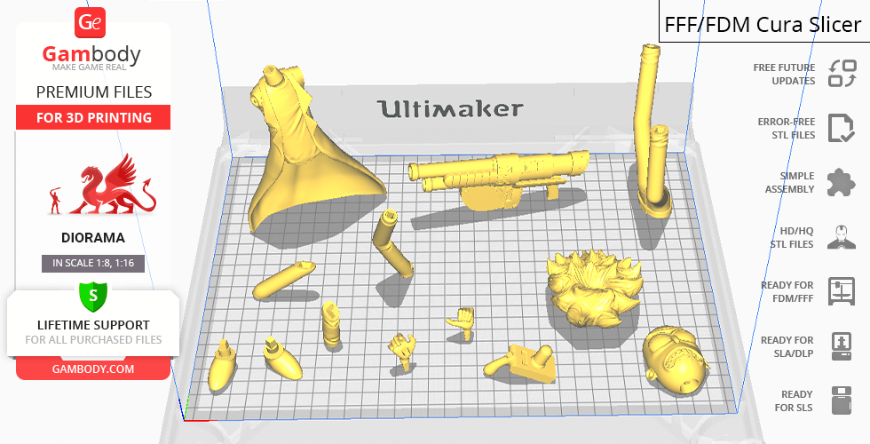
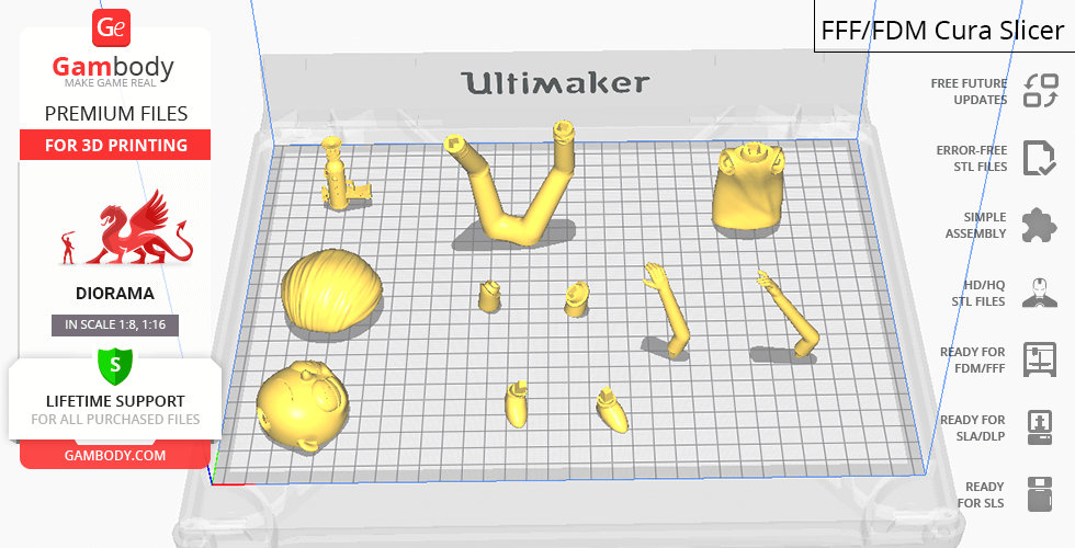
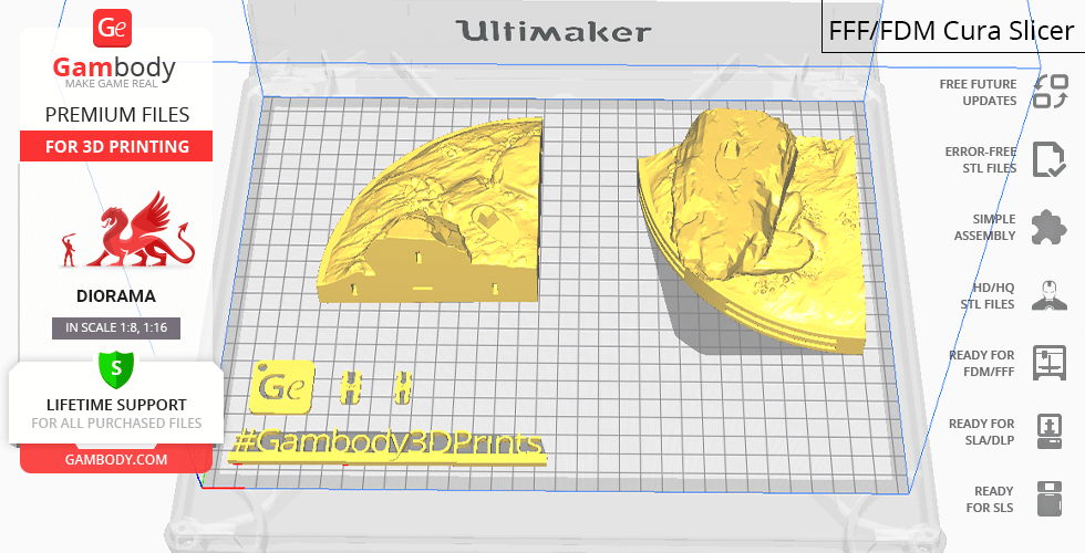
Rick & Morty Fight Scene figurines for 3D printing in diorama is a static assembly model and its moderation and adaptation for different types of 3D printers took Gambody team 42 hours in total. The diorama’s cutting was chosen by our team to minimize the amount of filament needed for generated support and some of the parts were hollowed out for you to save resin in the model’s Eco version. In order to conceal the places where the assembly parts of the model must be connected, the figurines were cut along the contour of both characters’ clothes and properly separated from the platform. What is more, in order to ensure an excellent quality of the 3D printed result, such smaller parts as both figurines’ hair, hands, boots, sleeves, etc. are provided as separate assembly elements. In addition to that, the Laser Gun was completely extracted from Morty’s grip, as well as the energy rifle that Rick figurine is depicted holding. The rocky platform was divided into several parts in order to fit the build plates of the smallest 3D printers. All the assembly parts come in STL files in recommended positions that were worked out in order to ensure the smoothness of the details’ surfaces after printing and to make sure that the 3D printing beginners won't face difficulties when placing the parts on a build plate. When downloading any model's file you will also receive "Assembly Manual" for FFF/FDM 1.0 and DLP/SLA 1.0 versions in PDF format.
The figurine is saved in STL files, a format supported by most 3D printers. All STL files for 3D printing have been checked in Netfabb and no errors were shown.
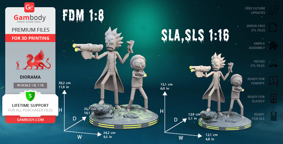
The model's scale was calculated from Rick's actual height that is 1940 mm. The 3D printing figurines' chosen scale is 1/8 for the FFF/FDM version and 1/16 for the DLP/SLA/SLS versions.
VERSIONS' SPECIFICATIONS
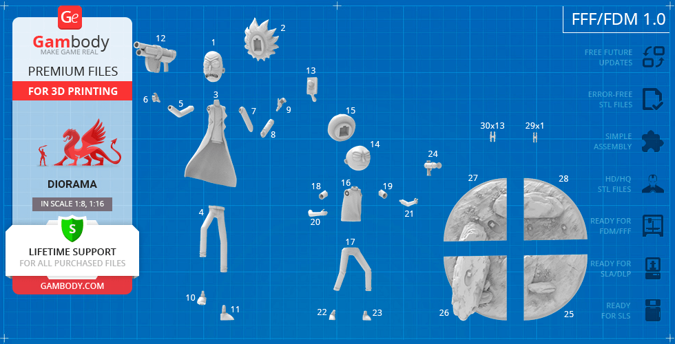
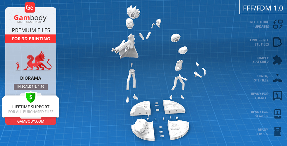
FFF/FDM 1.0 version features:- Contains 30 parts;- A printed model is 302 mm tall, 242 mm wide, 257 mm deep;- The assembly kit includes locks to connect the model's parts securely without glue. Lock 29_ge_lock_7S(x1) needs to be printed once; lock 30_ge_lock_10H(x13) needs to be printed 13 times;- All parts are divided in such a way that you will print them with the smallest number of support structures.
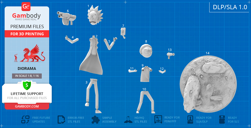
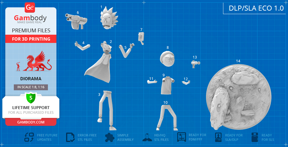
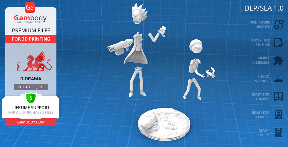
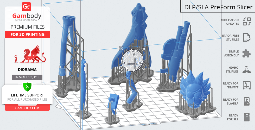
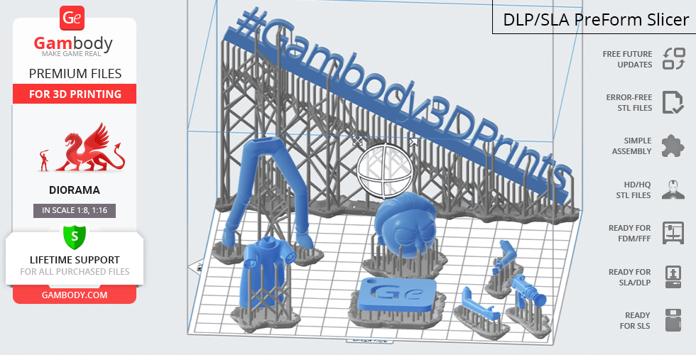
DLP/SLA 1.0 version features:- Contains 14 parts;- A printed model is 151 mm tall, 121 mm wide, 129 mm deep;- All parts are divided in such a way to fit the build plates and to ensure that support structures are generated where needed.
DLP/SLA Eco 1.0 version features:- Contains 14 parts;- A printed model is 151 mm tall, 121 mm wide, 129 mm deep;- Contains some hollowed out parts to save resin.
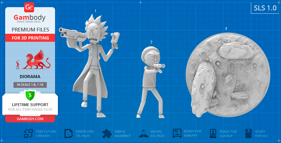
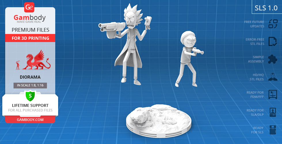
SLS 1.0 version features:- Made as a solid one-piece figurine;- A printed model is 151 mm tall, 121 mm wide, 129 mm deep;- Contains 3 parts - a one-piece Rick figurine and a solid Morty with the platform separated.
WHAT WILL YOU GET AFTER PURCHASE?
- STL files of Rick & Morty Fight Scene Models in Diorama for 3D Printing which consist of 61 parts;- 4 versions of files for this model for FFF/FDM, DLP/SLA, DLP/SLA Eco and SLS;- High-poly detailed figurines of Rick & Morty Fight Scene;- Assembly Manual for FFF/FDM 1.0 and DLP/SLA 1.0 versions in PDF format;- Detailed settings that we provide as a recommendation for Cura , Simplify3D and Slic3r for the best print;- Full technical support from the Gambody Support Team.
You can get the models of Rick & Morty Fight Scene in Diorama for 3D Printing immediately after the purchase! Just click the green Buy button in the top-right corner of the model’s page. You can pay with PayPal or your credit card.
Watch the tutorial on how to assemble Rick & Morty Fight Scene 3D Printing models in Diorama at Gambody YouTube channel.
Also, you may like the other Rick and Morty 3D Printing Diorama, Pickle Rick 3D Printing model, or other Cartoons 3D Printing Figurines.
_______FAQ: Where can I print a model if I have no printer?How to get started with 3D printing?How to set up my 3D printer?How to choose right 3D model print bed positioning? How to paint printed figurine?
Average customer rating (8 reviews)
3.4
Ratings breakdown
Click a star rating to filter reviews
Overall experience
Level of detail in the model
3.4
Model cut quality and assembly guide
3.4
Clarity and accuracy of the model page
3.4
Level of detail in the model
3
Model cut quality and assembly guide
3
Clarity and accuracy of the model page
3
Level of detail in the model
3
Model cut quality and assembly guide
3
Clarity and accuracy of the model page
3
Level of detail in the model
2
Model cut quality and assembly guide
2
Clarity and accuracy of the model page
2
Level of detail in the model
1
Model cut quality and assembly guide
1
Clarity and accuracy of the model page
1
Level of detail in the model
5
Model cut quality and assembly guide
5
Clarity and accuracy of the model page
5
Level of detail in the model
3
Model cut quality and assembly guide
3
Clarity and accuracy of the model page
3
Level of detail in the model
5
Model cut quality and assembly guide
5
Clarity and accuracy of the model page
5
Level of detail in the model
5
Model cut quality and assembly guide
5
Clarity and accuracy of the model page
5
To avoid printing issues and achieve the best quality, we highly recommend applying the following settings:
Generic
Below you can find printing recommendations for Cura, Simplify3D and Slic3r software.
Cura printing recommendations:
These are basic settings that were tested in Cura 4.8.0 slicer.
The test models were printed on Ultimaker 2, Creality Ender 3, Creality CR-10S Pro V2, Anycubic I3 Mega, Anycubic I3 MegaS 3D printers with PLA and PETG filaments.
Disclaimer: The following printing settings are a recommendation, not an obligation. The parameters can vary depending on the peculiarities of your 3D printer, the material you use and especially the particular assembly part at hand. Each part that any model comprises often needs preliminary review and you are free to tweak the settings the way you find suitable.
Note:
- You can scale up the model (downscaling is not recommended!);
- All connectors should be printed at 100% Infill;
- For all parts of locks (“ge_lock” in “Source files”) you need to change "Brim" type to "Skirt" in Build Plate Adhesionsection.
Quality
Layer Height: 0.12 mm (you can also set Layer Height at 0.16 or 0.2mm for 0.4mm nozzles)
Initial Layer Height: 0.2 mm (carefully level the print bed and keep your Initial Layer Height the same as the main Layer Height)
Line Width: 0.4 mm
Wall Line Width: 0.4 mm
Outer Wall Line Width: 0.4 mm
Inner Wall(s) Line Width: 0.4 mm
Top/Bottom Line Width: 0.4 mm
Infill Line Width: 0.4 mm
Skirt/Brim Line Width: 0.4 mm
Support Line Width: 0.4 mm
Initial Layer Line Width: 100%
Shell
Wall Thickness: 0.8 mm
Wall Line Count: 2
Outer Wall Wipe Distance: 0.3 mm
Top Surface Skin Layers: 0
Top/Bottom Thickness: 0.6 mm
Top Thickness: 0.6 mm
Top Layers: 5
Bottom Thickness: 0.6 mm
Bottom Layers: 5
Initial Bottom Layers: 5
Top/Bottom Pattern: Lines
Bottom Pattern Initial Layer: Lines
Top/Bottom Line Directions: [ ]
Outer Wall Inset: 0 mm
Optimize Wall Printing Order: Check
Compensate Wall Overlaps: Check
Compensate Inner Wall Overlaps: Check
Minimum Wall Flow: 0%
Fill Gaps Between Walls: Everywhere
Filter Out Tiny Gaps: Check
Horizontal Expansion: 0 mm
Initial Layer Horizontal Expansion: 0 mm
Hole horizontal expansion: 0
Z Seam Alignment: User Specified
Z Seam Position: Back
Z Seam X: Average length of your printer’s plate (e.g.”150” if your plate is 300mmon the X-axis)
Z Seam Y: A value higher than the length of your plate on the Y-axis (e.g. 700)
Seam Corner Preference: Hide Seam
Extra Skin Wall Count: 1
Skin Overlap Percentage: 10%
Skin Overlap 0.04 mm
Infill
Infill Density: 20% (for all smaller parts and for all parts of connectors use 100% Infill)
Infill Pattern: Triangles
Connect Infill Lines: Check
Infill Line Directions: [ ]
Infill X Offset: 0 mm
Infill Y Offset: 0 mm
Infill Line Multiplier: 1
Extra Infill Wall Count: 0
Infill Overlap Percentage: 10-20%
Infill Overlap: 0.04 mm
Skin Overlap Percentage: 5%
Skin Overlap: 0.02 mm
Infill Wipe Distance: 0 mm
Infill Layer Thickness: 0.24 mm
Gradual Infill Steps: 0
Infill Before Walls: Check
Minimum Infill Area: 0 mm2
Skin Removal Width: 0.8 mm
Top Skin Removal Width: 0.8 mm
Bottom Skin Removal Width: 0.8 mm
Skin Expand Distance: 0.8
Top Skin Expand Distance: 0.8
Bottom Skin Expand Distance: 0.8
Maximum Skin Angle for Expansion: 90˚
Minimum Skin Width for Expansion: 0.0
Skin Edge Support Thickness: 0
Skin Edge Support Layers: 0
Material
Initial Layer Flow: 100%
Printing Temperature: See your filament settings
Initial Printing Temperature: Your filament settings
Final Printing Temperature: Your filament settings
Build Plate Temperature: Your filament settings
Build Plate Temperature Initial Layer: Your filament settings + 5°
Flow: 100% (Important! If you face difficulty printing the model, you may need to adjust the Flow parameter. You may research the topic using the Internet or seek assistance at our Customer Support Team at support@gambody.com)
Speed
You can increase the printing Speed by 20% when you print simple objects. For small/thin parts you need to decrease the Speed by 25% - 50%.
Print Speed: 50 mm/s
Infill Speed: 50 mm/s
Wall Speed: 25 mm/s
Outer Wall Speed:25 mm/s
Inner Wall Speed: 50 mm/s
Top/Bottom Speed: 25mm/s
Support Speed: 25 mm/s
Support Infill Speed: 45 mm/s
Support Interface Speed: 25 mm/s
Support Roof Speed: 25 mm/s
Support Floor Speed: 25 mm/s
Travel Speed: 80 mm/s
Initial Layer Speed: 80 mm/s
Initial Layer Print Speed: 20 mm/s
Initial Layer Travel Speed: 80 mm/s
Skirt/Brim Speed: 20 mm/s
Z Hop Speed: 5 mm/s
Number of Slower Layers: 2
Enable Acceleration Control: Check
When printing simple objects, you need to set all Acceleration parameters at 500 mm/s. For small/thin parts you need to decrease the Acceleration by 50% - 70%.
Travel
Enable Retraction: Check
Retraction Distance: 4-8 mm, 1-3 mm for Direct Extruder (This is the most important retraction parameter. You can find your optimal value of Retraction Distance by printing any test object, e.g. bridges, towers etc.)
Retraction Speed: 25mm/s
Retraction Retract Speed: 25 mm/s
Retraction Prime Speed: 25 mm/s
Retraction Extra Prime Amount: 0 mm3
Retraction Minimum Travel: 1.5 mm
Maximum Retraction Count: 100
Minimum Extrusion Distance Window: 6,5 - 10 mm
Limit Support Retractions: Check
Combing Mode: All
Max Comb Distance With No Retract: 30 mm
Retract Before Outer Wall: Check
Avoid Printed Parts When Travelling: Check
Avoid Supports When Travelling: Check
Travel Avoid Distance: 1 mm
Layer Start X: 0.0 mm
Layer Start Y: 0.0 mm
Z Hop When Retracted: Check
Z Hop Height: 0,3 mm
Cooling
Enable Print Cooling: Check
Fan Speed: 100%
Regular Fan Speed: 100%
Maximum Fan Speed: 100%
Regular/Maximum Fan Speed Threshold: 10 s
Initial Fan Speed: 0%
Regular Fan Speed at Height: 0.36 mm
Regular Fan Speed at Layer: 3
Minimum Layer Time: 10 s
Minimum Speed: 10 mm/s
Support
Generate Support: Check
Support Structure: Normal (you can try using Tree Support Structure if you have difficulty printing any particular assembly part)
Support Placement: Everywhere
Support Overhang Angle: 60° (this parameter can range from 30° to 70° depending on the part at hand)
Support Pattern: Zig Zag
Support Wall Line Count: 1 (stronger support that might be more difficult to remove) 0 (less strong support but is easier to remove)
Support Density: 15%
Support Line Distance: 2.6667 mm
Initial layer support line distance: 2.667 mm
Support Z Distance: 0.12 mm
Support Top Distance: 0.12 mm
Support Bottom Distance: 0.12 mm
Support X/Y Distance: 0.8-1 mm
Support Distance Priority: Z overrides X/Y
Support Stair Step Height: 0.3 mm
Support Stair Step Maximum Width: 5.0 mm
Support Stair Step Minimum Slope Angle: 10°
Support Join Distance: 2.0 mm
Support Horizontal Expansion: 0.2 mm
Support Infill Layer Thickness: 0.2 mm
Gradual Support Infill Steps: 0
Minimum Support Area: 2 mm
Enable Support Interface: Check (generates additional “pillow” on the support structure that leads to a more even surface, but can be difficult to remove in hard-to-reach areas)
Enable Support Roof: Check
Enable Support Floor: Check
Support Interface Thickness: 0.8 mm
Support Roof Thickness: 0.8 mm
Support Floor Thickness: 0.8 mm
Support Interface Resolution 0.2 mm
Support Interface Density: 50-100%
Support Roof Density: 50-100%
Support Roof Line Distance: 0.8 mm
Support Floor Density: 50-100%
Support Floor line Distance: 0.4mm
Support Interface Pattern: Grid
Support Roof Pattern: Grid (this parameter should differ from Bottom Pattern Initial Layer in “Shell” section)
Support Floor Pattern: Grid
Minimum Support Interface Area: 10mm
Minimum Support Roof Area: 10 mm
Minimum Support Floor Area: 10 mm
Support Interface Horizontal Expansion: 0.0 mm
Support Roof Horizontal Expansion: 0.0 mm
Support Floor Horizontal Expansion: 0.0 mm
Fan Speed Override: Check
Supported Skin Fan Speed: 100%
Use Towers: Check
Tower Diameter: 4 mm
Minimum Diameter: 3.0 mm
Tower Roof Angle: 65°
Build Plate Adhesion
Build Plate Adhesion Type: Skirt/Brim (For unsteady parts, and those parts that may come unstuck use “Brim”. For bigger assembly parts that have large adhesion area and for all parts of locks and claws that you want to come out clean use "Skirt")
Skirt/Brim Minimum Length: 250 mm
Brim Width: 8.0 mm
Brim Line Count: 10
Brim Only on Outside: Check
Mesh Fixes
Union Overlapping Volumes: Check
Merged Meshes Overlap: 0.15 mm
Special Modes
Print Sequence: All at Once
Surface Mode: Normal
Experimental
Slicing Tolerance: Middle
Maximum Resolution: 0.01 mm
Flow rate compensation max extrusion offset: 0 mm
Flow rate compensation factor: 100%
Simplify3D printing recommendations:
This model was tested with PLA material.
To avoid printing problems, we recommend the following settings:
Extruder
Nozzle Diameter: 0.4 mm
Extrusion Multiplier: 0.97
Extrusion Width: Auto
Retraction Distance: 5.00 mm
Extra Restart Distance: 0.00 mm
Retraction Vertical Lift: 0.08 mm
Retraction Speed: 5400.0 mm/min
Wipe Distance: 5.00 mm
Layer
Primary Layer Height: 0.2 mm
Top Solid Layers: 8
Bottom Solid Layers: 5
Outline/Perimeter Shells: 2
Outline Direction: Inside-Out
First Layer Height: 90%
First Layer Width: 100%
First Layer Speed: 20%
Additions
Use Skirt/Brim: Check
Skirt Layers: 1
Skirt Offset from Part: 6.00 mm
Skirt Outlines: 5
Infill
Internal Fill Pattern: Fast Honeycomb
External Fill Patern: Rectilinear
Interior Fill Percentage: 10%
Outline Overlap: 22%
Infill Extrusion Width: 100%
Minimum Infill Length: 5.00 mm
Combine Infill Every: 1 layers
External Infill Angle Offsets: 45/-45 deg
Support
Generate Support Material: Check
Support Infill Percentage: 15%
Extra Inflation Distance: 1.00 mm
Support Base Layers: 0
Combine Support Every: 1 layers
Dense Support Layers: 0
Dense Infill Percentage: 70%
Support Type: Normal
Support Pillar Resolution: 5.00 mm
Max Overhang Angle: 60 deg
Horizontal Offset From Part: 0.50 mm
Upper Vertical Separation Layers: 1
Lower Vertical Separation Layers: 1
Support Infill Angles: 45 deg
Temperature
Extruder 1 Temperature: 210
Heated Bed: 60
Cooling
Increase fan speed for layers below: 45.0 sec
Maximum Cooling fan speed: 50%
Bridging fan speed override: 100%
Speeds
Default Printing Speed: 4800.0 mm/min
Outline Underspeed: 50%
Solid Infill Underspeed: 80%
Support Structure Underspeed: 80%
X/Y Axis Movement Speed: 10800.0 mm/min
Z Axis Movemen Speed: 1002.0 mm/min
Adjust printing speed for layers below: 15.0 sec
Allow speed reduction down to: 20%
Other
Unsupported area threshold: 20.0 sq m
Slic3r printing recommendations:
Layer height
Layer height: 0.1 mm
First layer height: 90%
Vertical shells
Perimeters: 2
Horizontal shells
Soid layers:
Top: 8
Bottom: 5
Quality
Detect thin walls: Check
Detect bridging perimeters: Check
Advanced
Seam position: Random
Infill
Fill desity: 20%
Fill pattern: Honeycomb
Top/bottom fill pattern: Rectilinear
Reducing printing time
Combine infill every: 1 layers
Advanced
Solid infill every: 0 layers
Fill angle: 25 deg
Solid infill threshold area: 0mm
Skirt
Loops: 2
Distance from object: 6 mm
Skirt height: 1 layers
Minimum extrusion length: 4 mm
Brim
Brim width: 10 mm
Support material
Generate support material: Check
Overhang threshold: 45 deg
Enforce support for the first: 3 layers
Raft
Raft layers: 0 layers
Options for support material and raft
Contact Z distance: 0.1 mm
Pattern: Rectilinear
Patter spacing: 2 mm
Pattern angle: 0 deg
Interface layers: 2 layers
Interface pattern spacing: 0.2 mm
Speed for print moves
Perimeters: 60 mm/s
Small perimeters: 20 mm/s
External perimeters: 20 mm/s
Infill: 60 mm/s
Solid infill: 60 mm/s
Top solid infill: 30 mm/s
Support material: 50 mm/s
Support material interface: 100%
Bridges: 30 mm/s
Gap fill: 50 mm/s
Speed for non-print moves
Travel: 60 mm/s
Modifiers
First layer speed: 30 mm/s
Acceleration control
Perimeters: 800 mm/s
Infill: 1500 mm/s
Bridge: 1000 mm/s
First layer: 1000 mm/s
Default: 1000 mm/s
Autospeed
Max print speed: 100 mm/s
Max volumetrix speed: 0 mm/s
Extrusion width
Default extrusion width: 0.42 mm
First layer: 0.42 mm
Perimeters: 0.42 mm
External perimeters: 0.42 mm
Infill: 0.42 mm
Solid infill: 0.42 mm
Top solid infill: 0.42 mm
Support material: 0.42 mm
Overlap
Infill/Perimeters overlap: 20%
Flow
Bridge flow ratio: 0.95
Other
XY Size Compensation: 0 mm
Threds: 8
Resolution: 0 mm