


Files
3D model format
Stereolithography (.stl)
Total files
Slicer settings
not available
Mesh error check
not specified
Support
Lifetime support from Gambody team
Update requests
not specified
Model versions
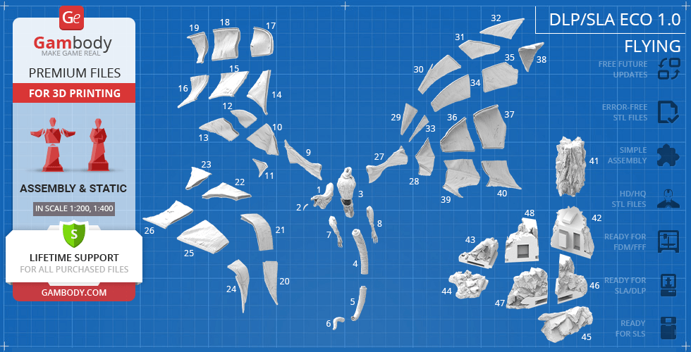
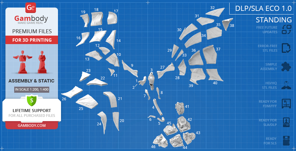
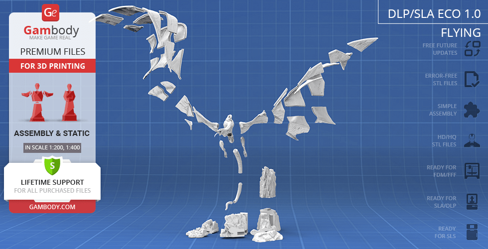
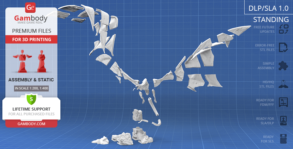
DLP/SLA
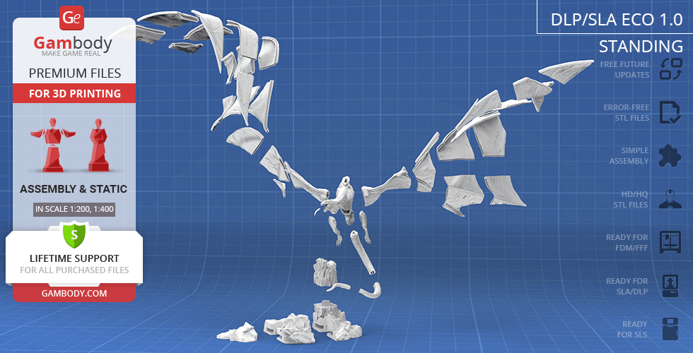
Eco parts
Assembly method
Connectors, Glue
Features
Some parts are hollowed out to save resin. The assembly parts are connected using specially designed integrated connectors that fit securely into the corresponding slots. Optionally, for added strength and rigidity, the static connections can be glued together;
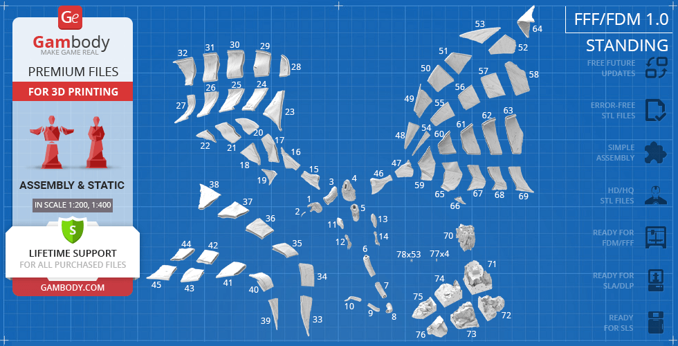
FFF/FDM
Assembly method
Connectors, Ge-Locks, Glue
Features
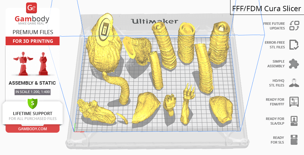
The assembly parts are connected using specially designed integrated connectors that fit securely into the corresponding slots. Some model parts use separate connectors (part "77_ge_lock_7S(x4)", requires 4 copies, and "78_ge_lock_10H(x53)" needs to be printed 53 times ). Optionally, for added strength and rigidity, the static connections can be glued together;
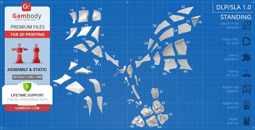
DLP/SLA
Eco parts
Assembly method
Connectors, Glue
Features
The assembly parts are connected using specially designed integrated connectors that fit securely into the corresponding slots. Optionally, for added strength and rigidity, the static connections can be glued together;
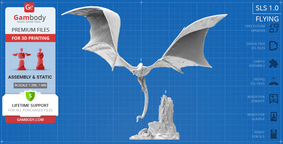
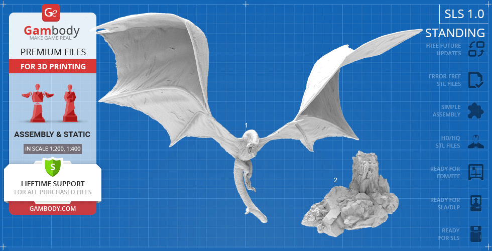
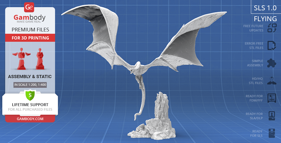
SLS
Assembly method
Connectors, Glue
Features
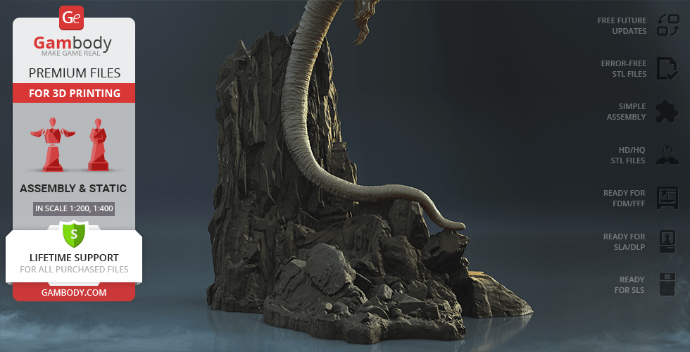
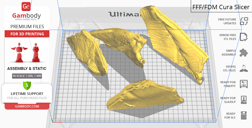
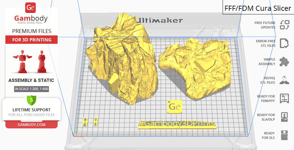
A solid Vhagar model and a rock. The assembly parts are connected using specially designed integrated connectors that fit securely into the corresponding slots. Optionally, for added strength and rigidity, the static connections can be glued together;
DLP/SLA
Eco parts
Assembly method
Connectors, Glue
Features
Some parts are hollowed out to save resin. The assembly parts are connected using specially designed integrated connectors that fit securely into the corresponding slots. Optionally, for added strength and rigidity, the static connections can be glued together;
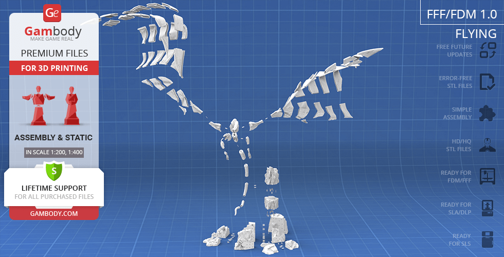
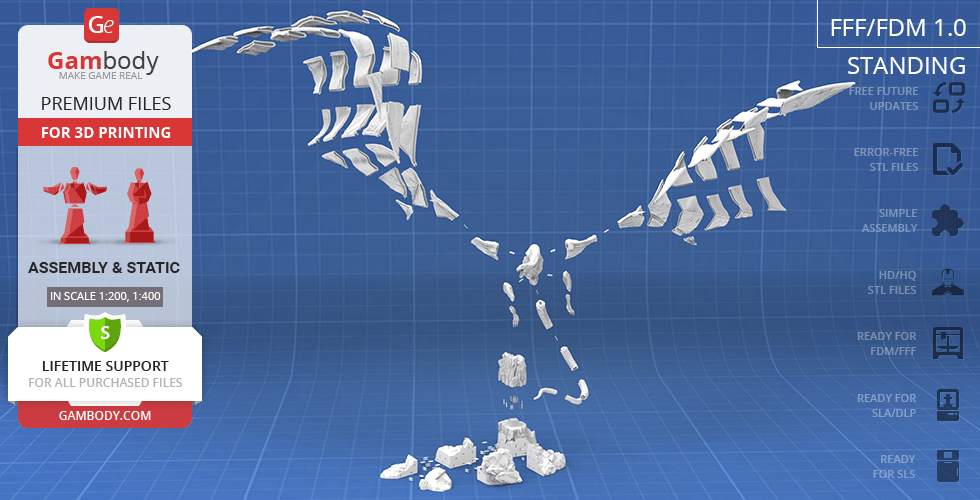
FFF/FDM
Assembly method
Connectors, Ge-Locks, Glue
Features
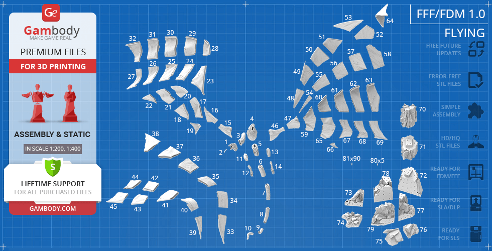
The assembly parts are connected using specially designed integrated connectors that fit securely into the corresponding slots. Some model parts use separate connectors (part "80_ge_lock_7S(x5)", requires 5 copies, and "81_ge_lock_10H(x90)" needs to be printed 90 times ). Optionally, for added strength and rigidity, the static connections can be glued together;
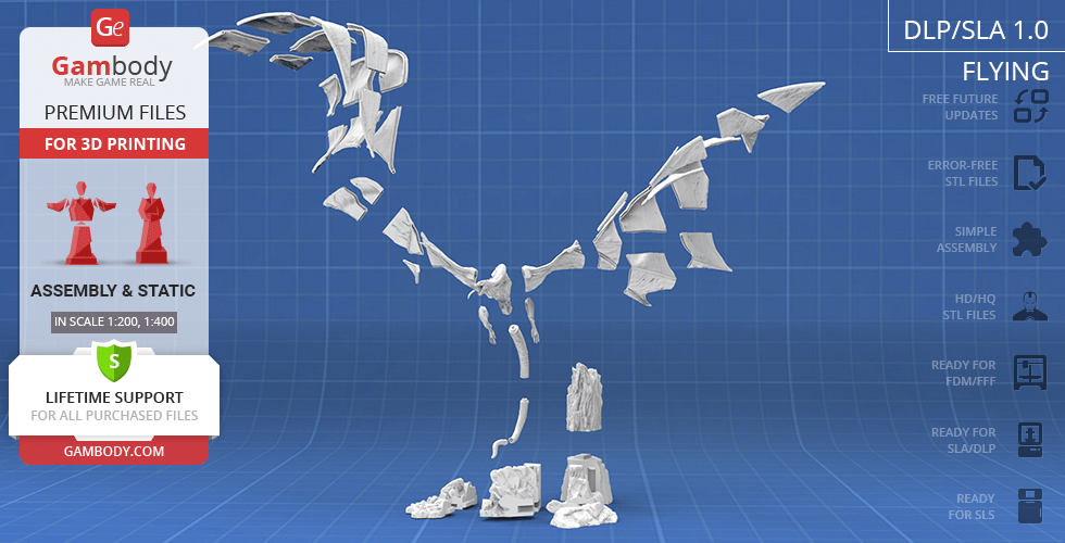
DLP/SLA
Eco parts
Assembly method
Connectors, Glue
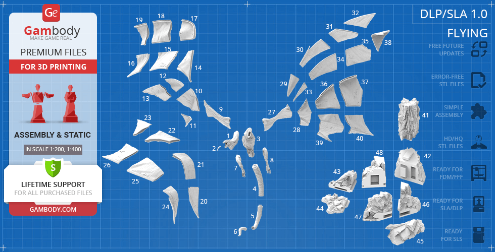
Features
The assembly parts are connected using specially designed integrated connectors that fit securely into the corresponding slots. Optionally, for added strength and rigidity, the static connections can be glued together;
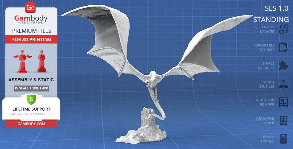
SLS
Assembly method
Connectors, Glue
Features
A solid Vhagar model and a rock. The assembly parts are connected using specially designed integrated connectors that fit securely into the corresponding slots. Optionally, for added strength and rigidity, the static connections can be glued together;
Additional details
Part of diorama
No
Special pack included
No
You can get the STL files of Vhagar Dragon model immediately after the purchase! Just click the green Buy button in the top-right corner of the model’s page. You can pay with PayPal or your credit card.
Watch the tutorial on how to assemble the 3D Printed Vhagar Dragon model from the provided 3D Print Files on Gambody YouTube channel.
Also, you may like other Dragons 3D Printing Designs.
_______
FAQ:
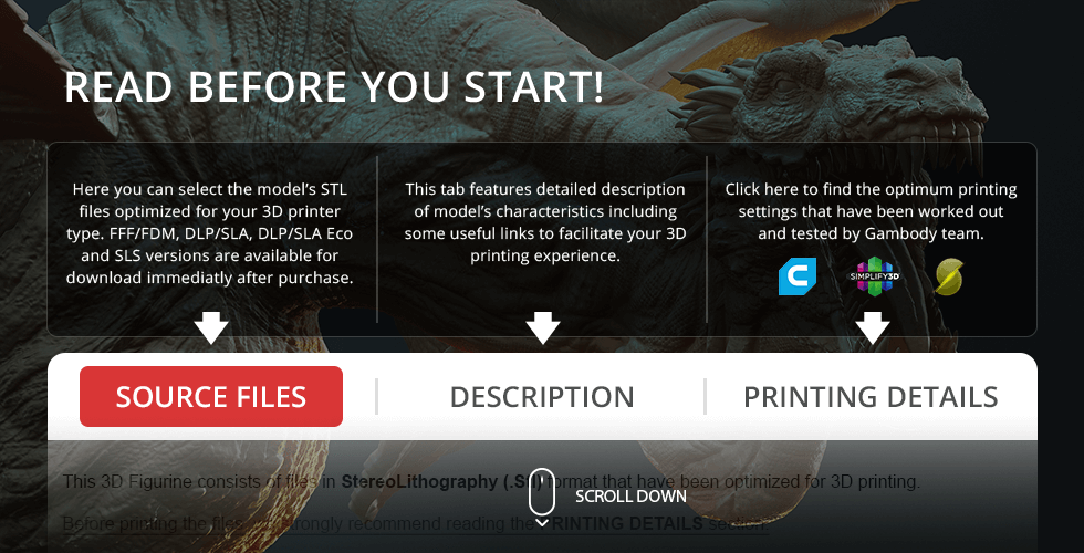
This 3D model comes with StereoLithography (.STL) files optimized for 3D printing. You'll get digital files, not a physical product
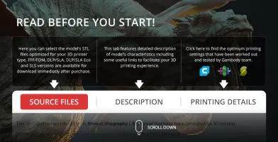
Before printing, take a look at Printing Details for recommended settings and tips to achieve better results.
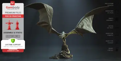
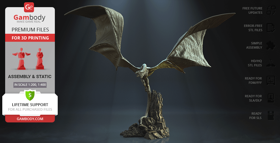
Vhagar Dragon 3D Printer Files | Assembly includes 3 version(s) for the supported 3D printer type(s): FFF/FDM, DLP/SLA, SLS. Files are available for download after purchase.
See the Description and Specifications sections for more details about this model.
3D model history
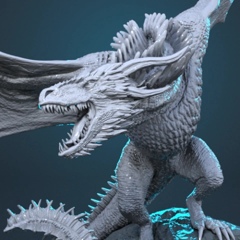
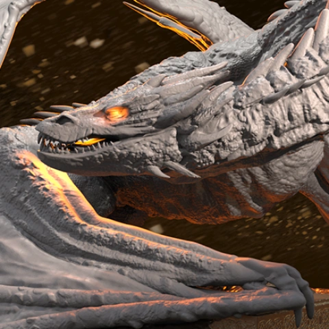
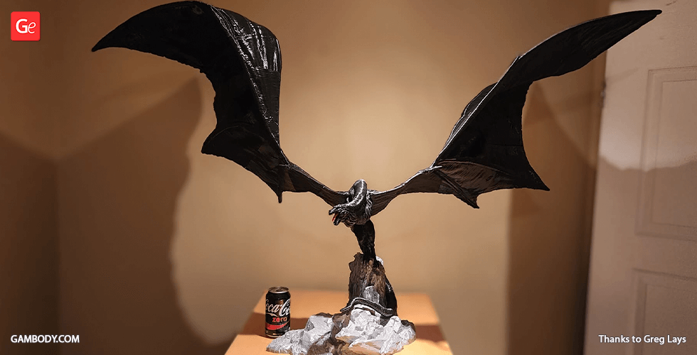
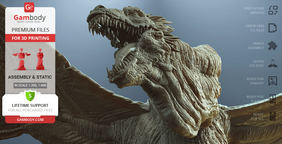
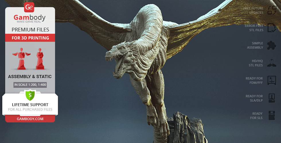
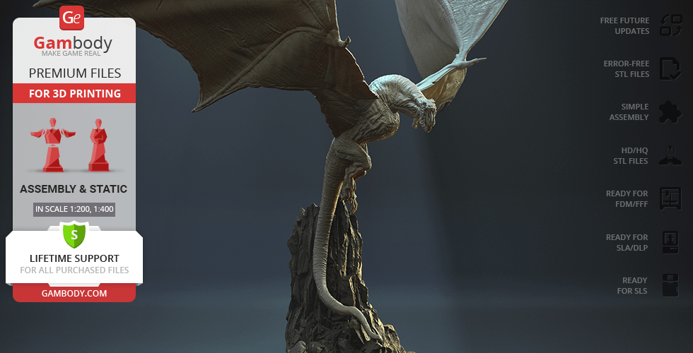
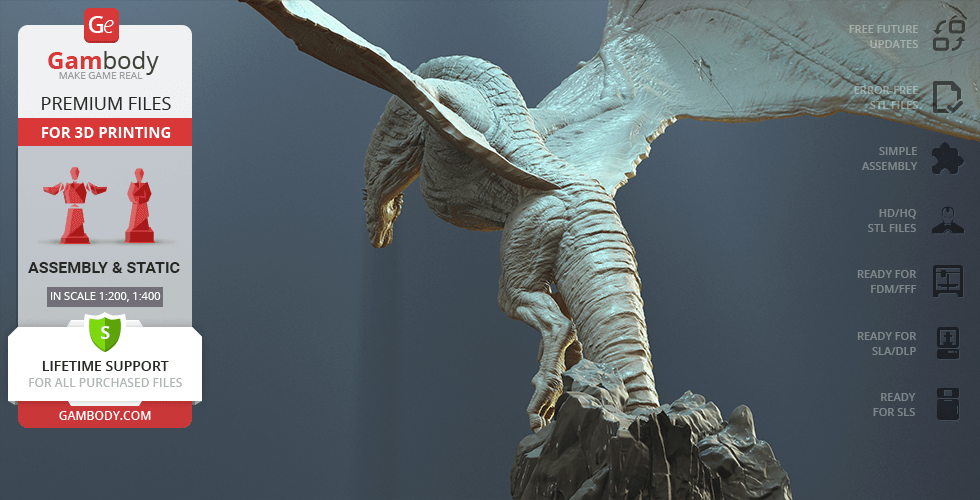
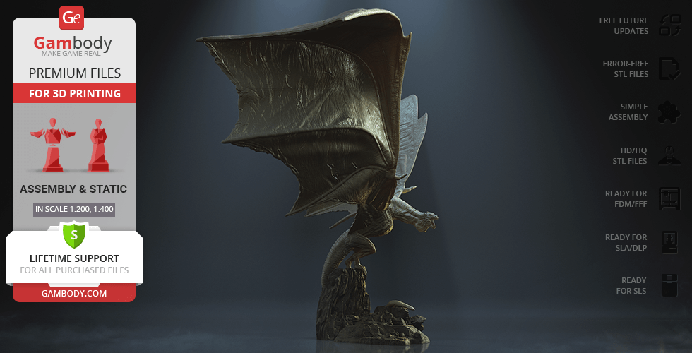
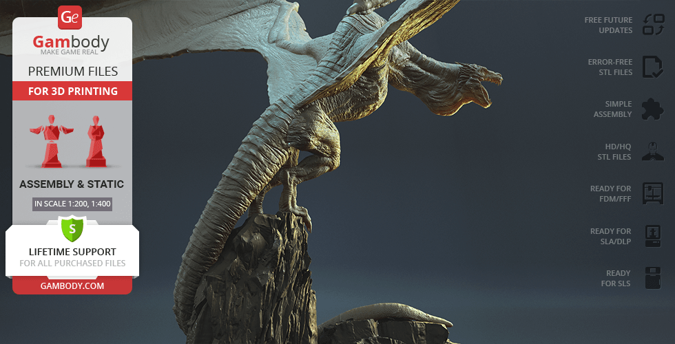
The mighty dragon of Visenya, the Queen of All Dragons, Vhagar is remembered by all fans of “House of Dragon” and “Game of Thrones” for its enormous proportions and extreme power. Vhagar was large enough that one could ride a horse down her gullet; her breath was so hot that it could melt a knight's armor and cook him inside.
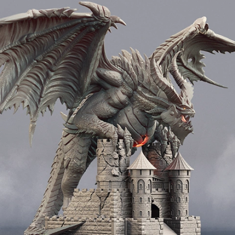
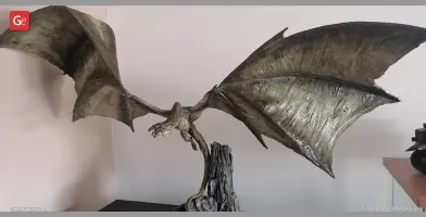
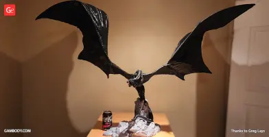
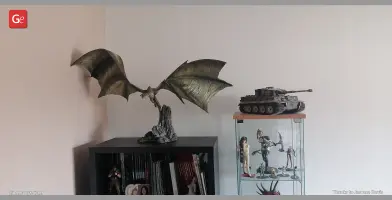
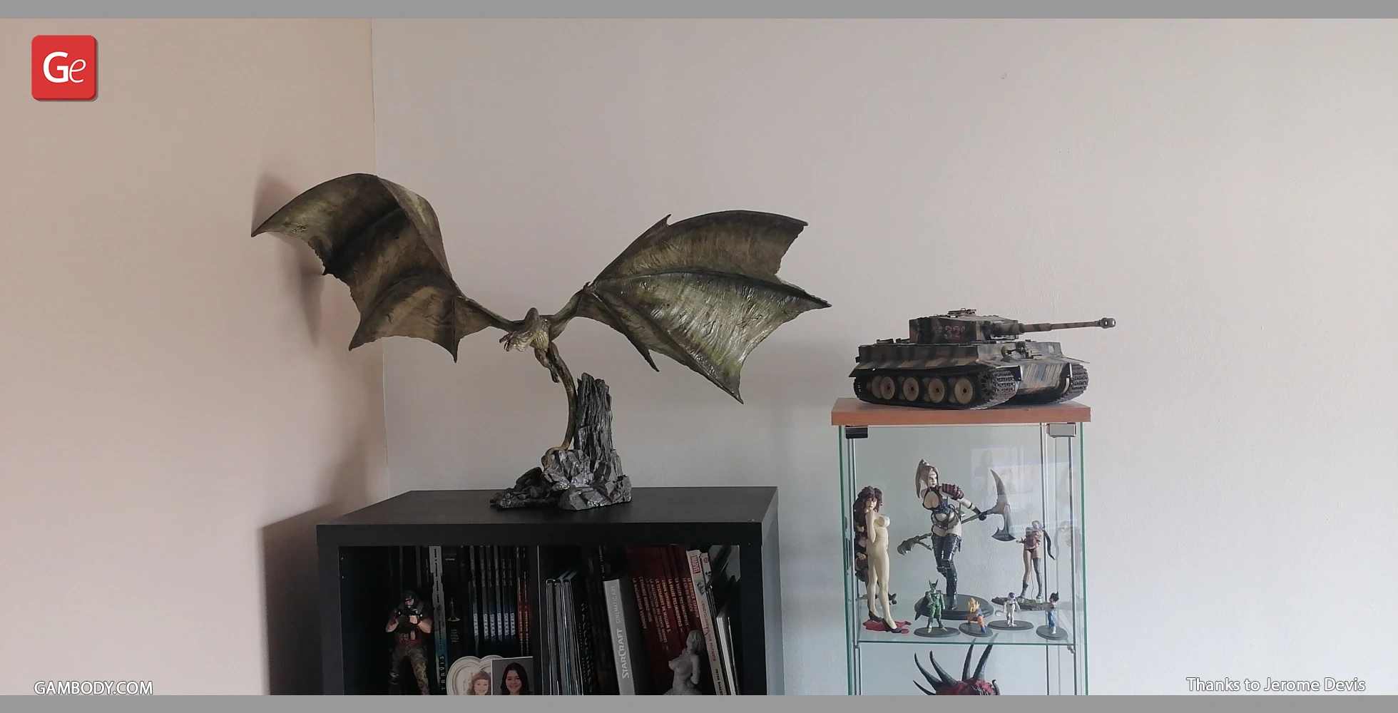
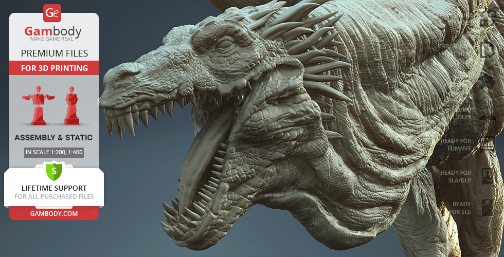
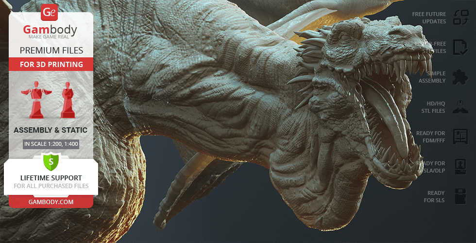
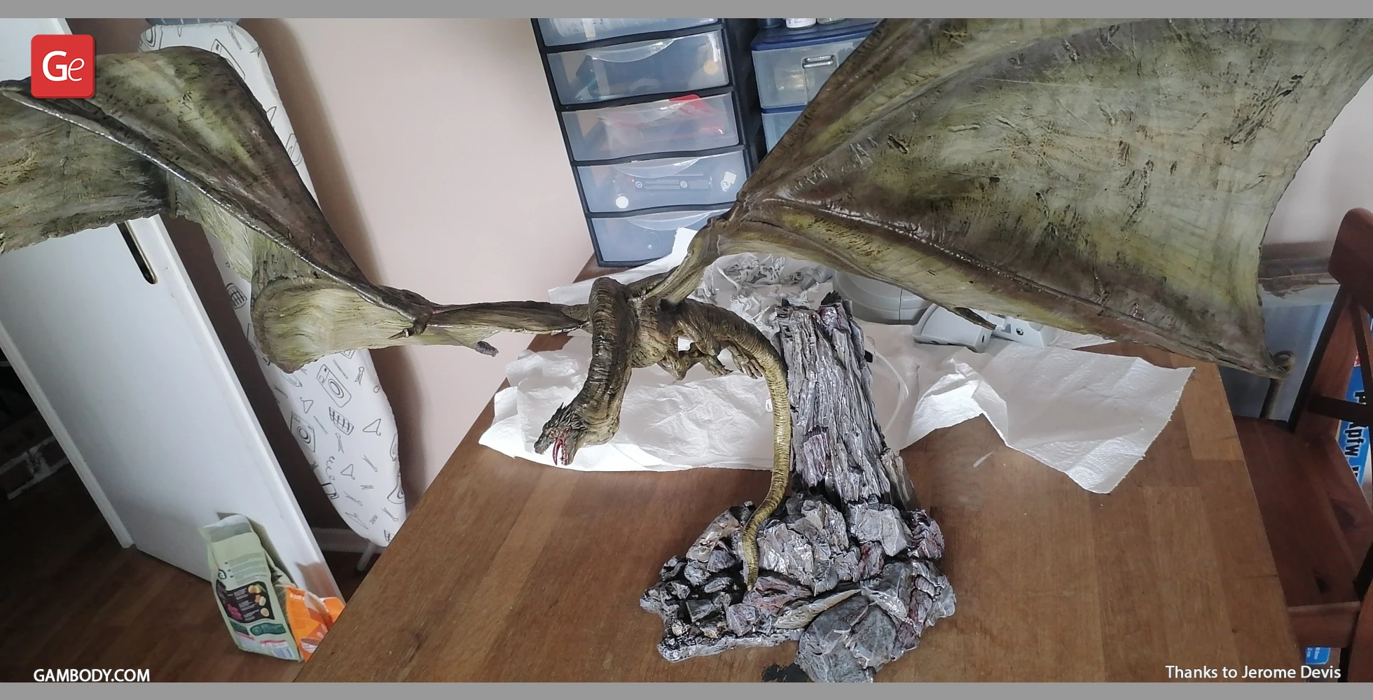
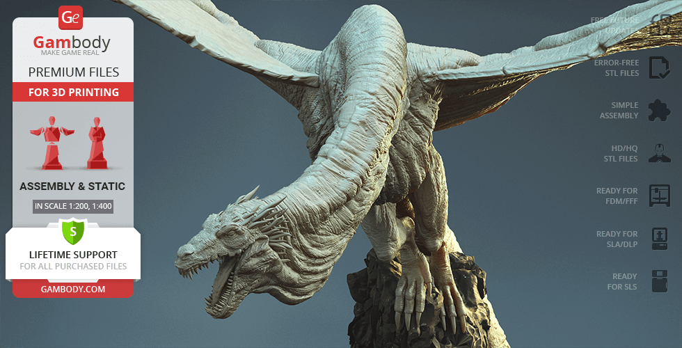
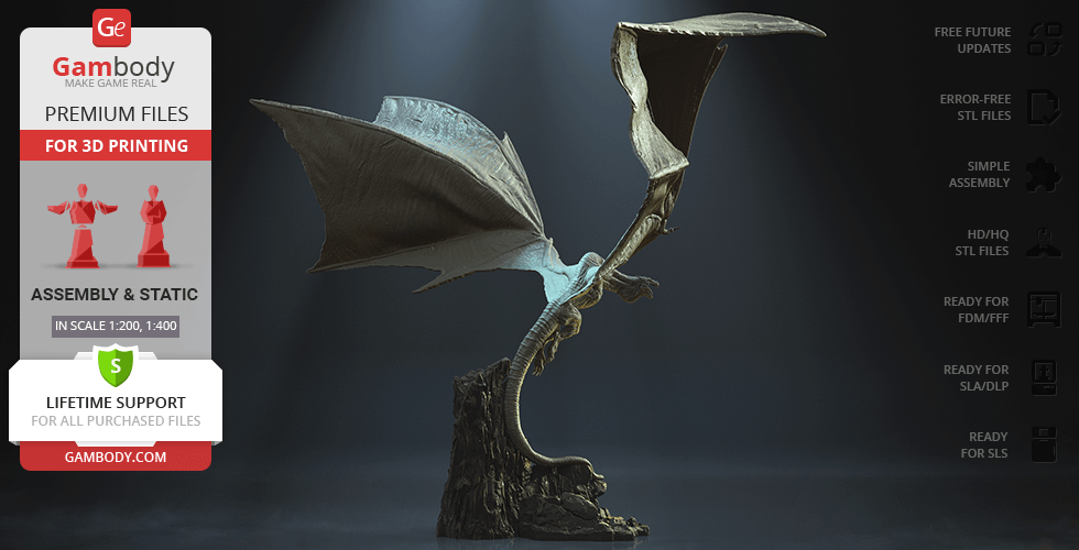
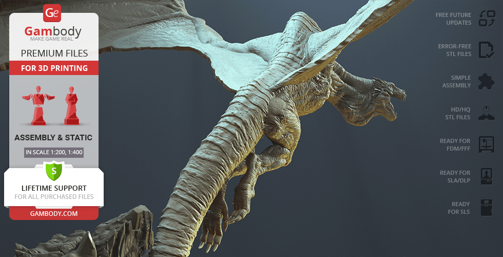
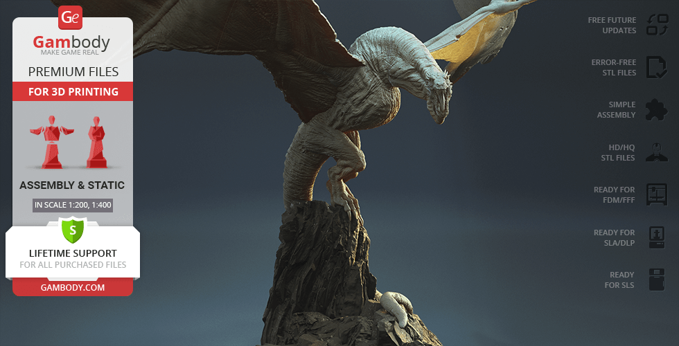
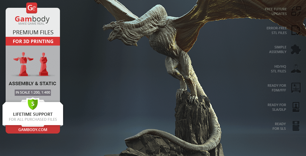
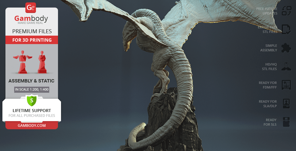
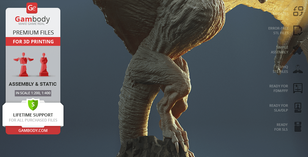
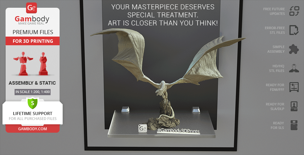
Inspired by the “House of the Dragon” fantasy drama television series, our contributing 3D artist created this outstanding, absolutely amazing and spectacular 3D model of Vhagar. The posture of the Queen of All Dragons emits power and ferocity, she is ready to sweep away everything and everyone on her path. The gigantic muscular body, strong legs and massive wings don’t make us doubt her strength and domination. The tiny scale on the dragon’s face, its sharp canines, and the horns on the neck, all these small details reflect the great meticulousness of the author and their admiration for the character he created. We can’t but admire this great project and hope that you will share our feelings by 3D printing it!
3D printing model features
Model-specific features:
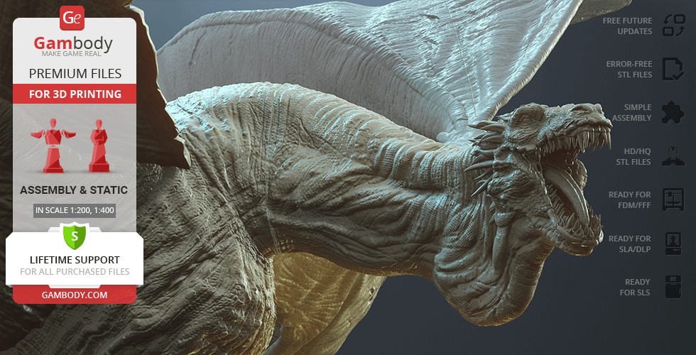
- The model's anatomy and proportions were thoroughly reviewed during the moderation process for the dragon to look harmonically in the intended pose;
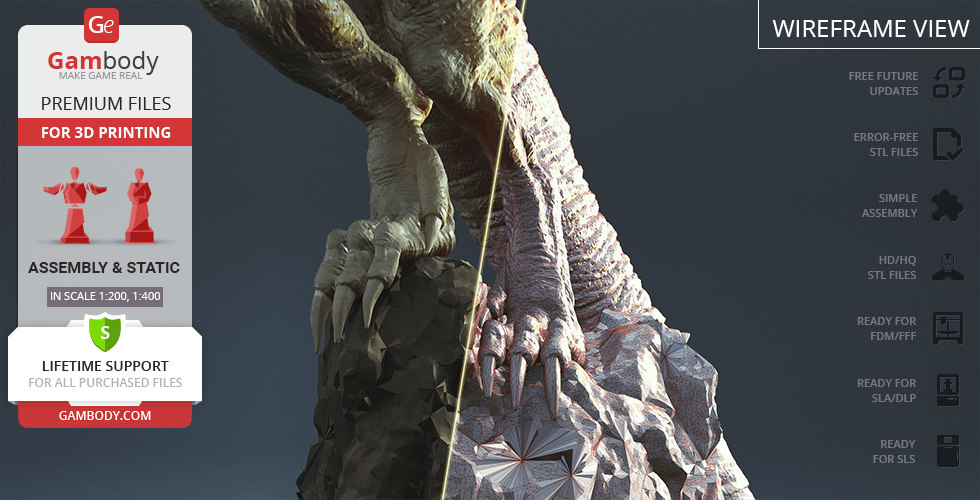
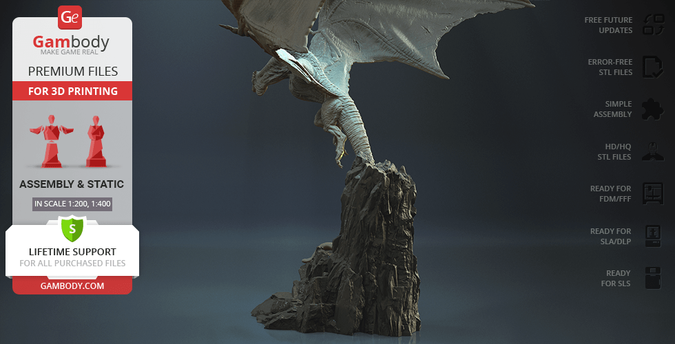
- To conceal the places where the assembly parts of the models are connected, the model was cut along the contour of Vhagar’s body;
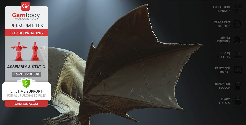
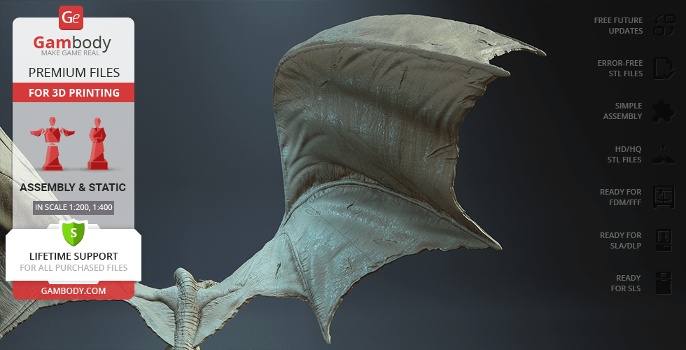
- The dragon's head, horns, wings, legs, etc. are provided as separate assembly parts;
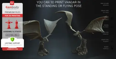
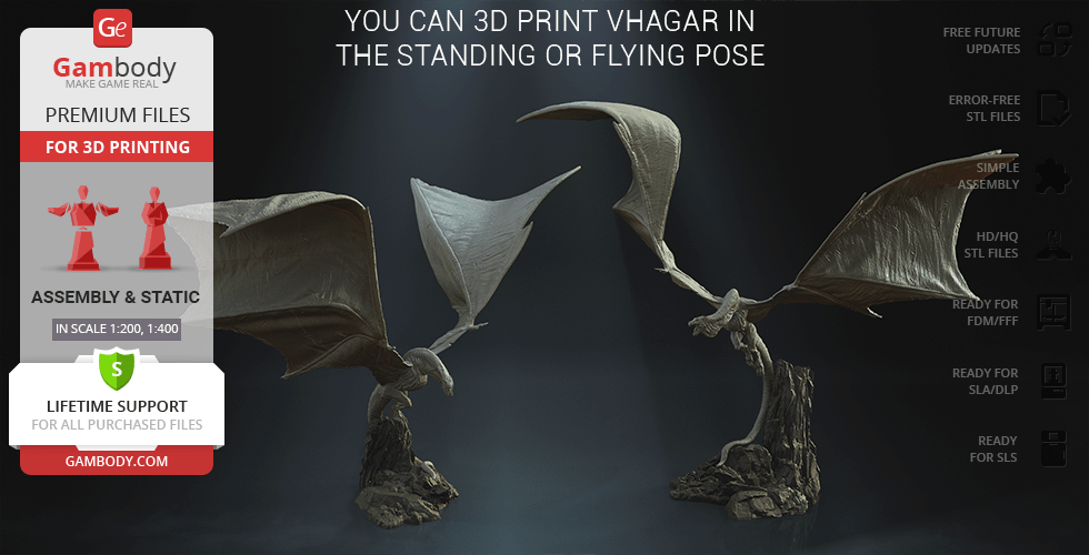
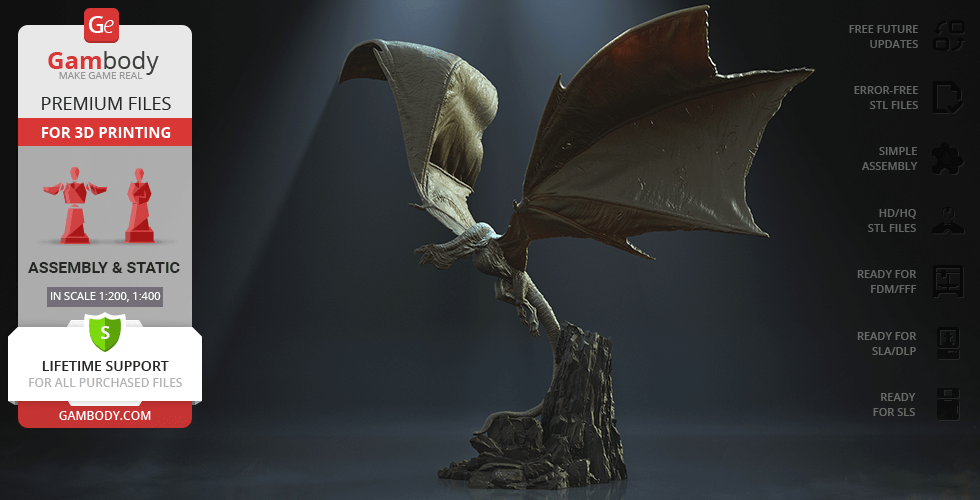
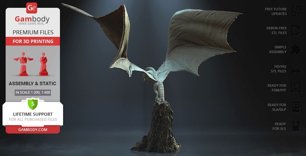
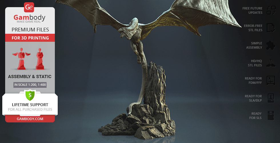
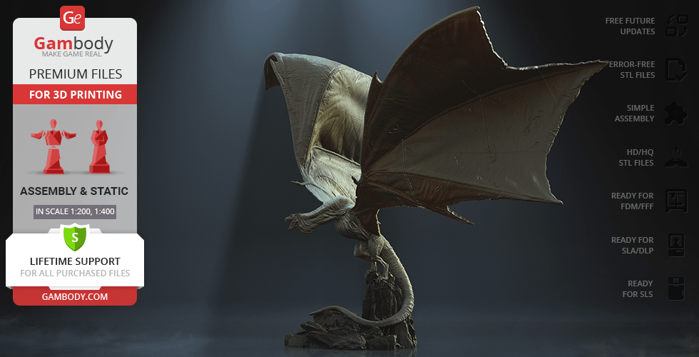
- Two designs - Standing Vhagar and Flying Vhagar;
Printing & assembly details:
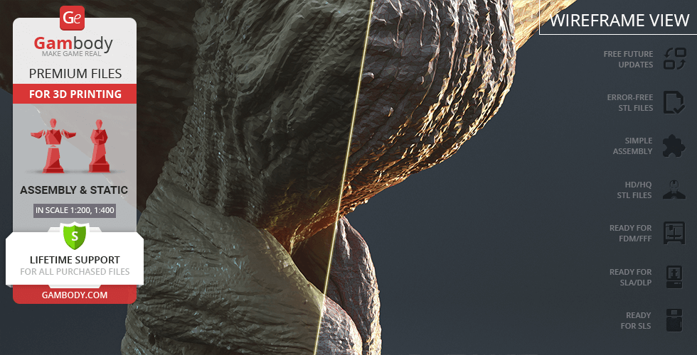
- Provided as error-free STL files compatible with most 3D printers;
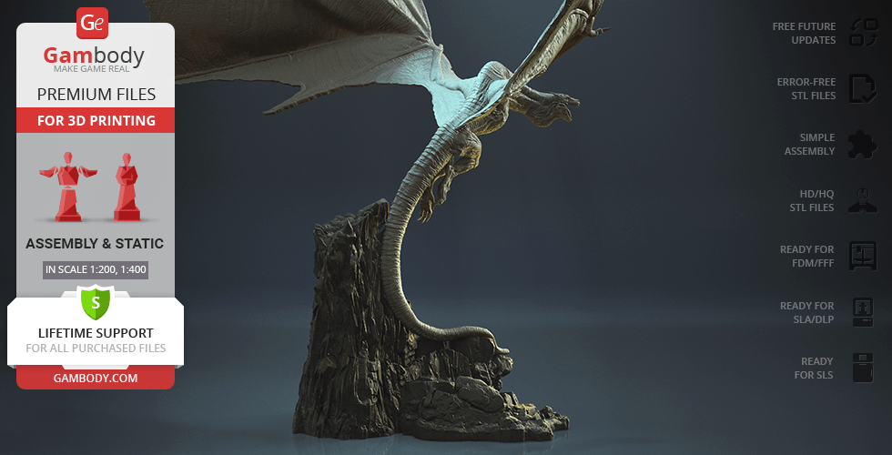
- Optimized part division minimizes support material and ensures smooth surface detail;
- The assembly parts in the FFF/FDM version come in the recommended print orientations for easy bed placement;
- Assembly manual in PDF and video formats is included for both FFF/FDM and DLP/SLA versions;
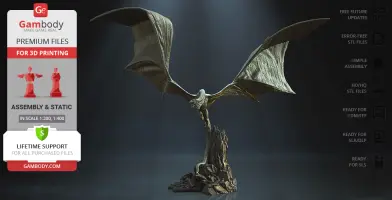
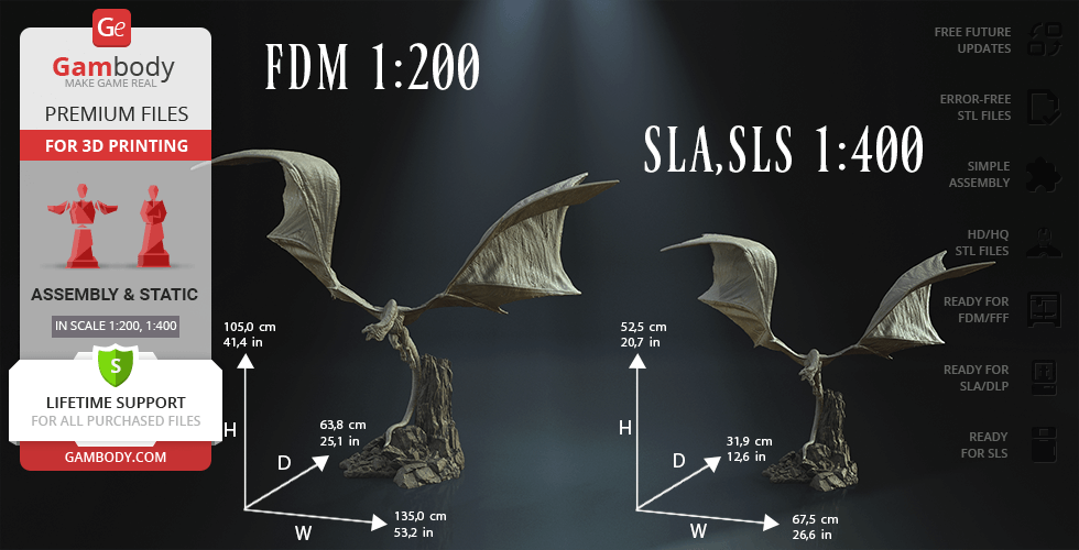
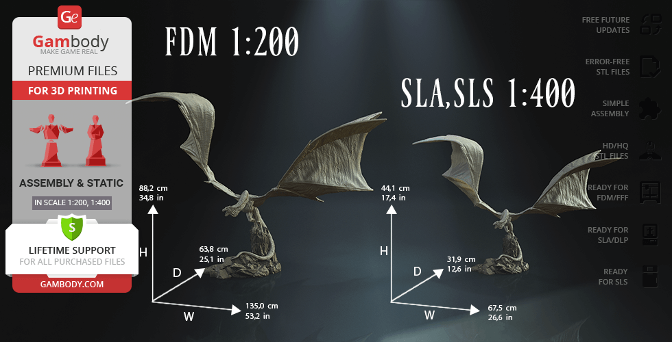
- The model is available in recommended scales of 1:200 for the FFF/FDM version and 1:400 for the DLP/SLA/SLS versions, based on approximate height of Vhagar (150 000 mm).
What will you get after purchase?
- 8 versions of Vhagar Dragon STL files for FFF/FDM, DLP/SLA, DLP/SLA Eco, and SLS — files for all versions are available for download after the purchase;
- STL files of high-poly Vhagar Dragon model for 3D printing consist of 351 files;
- Sizes for:
- FFF/FDM Standing: 1350 mm wide, 882 mm high, 638 mm deep;
- FFF/FDM Flying: 1350 mm wide, 1050 mm high, 638 mm deep;
- DLP/SLA/SLS Standing: 675 mm wide, 441 mm high, 319 mm deep;
- DLP/SLA/SLS Flying: 675 mm wide, 525 mm high, 319 mm deep;
- Assembly Manual for 1.0 FFF/FDM and 1.0 DLP/SLA versions in PDF and video formats;
- Detailed settings that we provide as a recommendation for Bambu Studio, Cura, Orca Slicer, PrusaSlicer, Simplify3D, and Slic3r for the best print;
- Full technical support from the Gambody Support Team.
Average customer rating (10 reviews)
3.7
Ratings breakdown
Click a star rating to filter reviews
Overall experience
Level of detail in the model
3.7
Model cut quality and assembly guide
3.7
Clarity and accuracy of the model page
3.7
Level of detail in the model
1
Model cut quality and assembly guide
1
Clarity and accuracy of the model page
1
Level of detail in the model
5
Model cut quality and assembly guide
5
Clarity and accuracy of the model page
5
Level of detail in the model
5
Model cut quality and assembly guide
5
Clarity and accuracy of the model page
5
Level of detail in the model
5
Model cut quality and assembly guide
5
Clarity and accuracy of the model page
5
Level of detail in the model
5
Model cut quality and assembly guide
5
Clarity and accuracy of the model page
5
Level of detail in the model
1
Model cut quality and assembly guide
1
Clarity and accuracy of the model page
1
Level of detail in the model
1
Model cut quality and assembly guide
1
Clarity and accuracy of the model page
1
Level of detail in the model
4
Model cut quality and assembly guide
4
Clarity and accuracy of the model page
4
Level of detail in the model
5
Model cut quality and assembly guide
5
Clarity and accuracy of the model page
5
Level of detail in the model
5
Model cut quality and assembly guide
5
Clarity and accuracy of the model page
5
To avoid printing issues and achieve the best quality, we highly recommend applying the following settings:
Generic
Below you can find printing recommendations for Bambu Studio, Cura, Orca Slicer, PrusaSlicer, Simplify3D, and Slic3r software.
Disclaimer: The following printing settings are a recommendation, not an obligation. The parameters can vary depending on the peculiarities of your 3D printer, the material you use, and especially the particular assembly part you are working with. Each part that any model comprises often needs preliminary review, and you are free to tweak the settings the way you find suitable.
Note:
You can scale up the model (downscaling for FFF/FDM 3D printers is not recommended!);
All connectors should be printed at 100% Infill.
Bambu Lab printing recommendations:
These basic 3D printing settings recommendations for beginners were tested in Bambu Studio 1.9.1. Test models were printed on the Bambu Lab A1, Bambu Lab A1 Mini, Creality Ender 3 S1, Anycubic Kobra 2, and Anycubic Vyper using PLA and PETG filaments.
To avoid printing problems, we recommend the following settings:download
Cura printing recommendations:
These are averaged settings which were tested in the Cura 5.2.1 slicer. Test models were printed on Anycubic Vyper, Creality Ender 3 Pro with PLA filament.
To avoid printing problems, we recommend the following settings: download
Orca Slicer printing recommendations:
These basic 3D printing settings recommendations for beginners were tested in Orca Slicer 2.3.0. Test models were printed on Bambu Lab A1, Bambu Lab A1 Mini, Creality Ender 3 V3, and Anycubic Kobra 3 with PLA and PETG filament.
To avoid printing problems, we recommend the following settings: download
PrusaSlicer printing recommendations:
These basic 3D printing settings recommendations for beginners were tested in PrusaSlicer 2.3.1. Test models were printed on Ultimaker 2, Creality Ender 3, Creality Cr-10S pro v2, Anycubic I3 Mega, Anycubic I3 MegaS, Anycubic Vyper with PLA and PETG filaments.
To avoid printing problems, we recommend the following settings:download
Simplify3D printing recommendations:
These are averaged settings which were tested in the Simplify3D 5.0.0 slicer. Test models were printed on Anycubic Vyper, FLSUN v400, Ender3 S1 with PLA filament.
To avoid printing problems, we recommend the following settings:download
Slic3r printing recommendations:
These basic 3D printing settings recommendations for beginners were tested in Slic3r 1.3.0 software. Test models were printed on Ultimaker 2, Creality Ender 3, Creality Cr-10S pro v2, Anycubic I3 Mega, Anycubic I3 MegaS, Anycubic Vyper with PLA and PetG filaments.
To avoid printing problems, we recommend the following settings:download
SLS
A solid Vhagar model and a rock. The assembly parts are connected using specially designed integrated connectors that fit securely into the corresponding slots. Optionally, for added strength and rigidity, the static connections can be glued together;
SLS
A solid Vhagar model and a rock. The assembly parts are connected using specially designed integrated connectors that fit securely into the corresponding slots. Optionally, for added strength and rigidity, the static connections can be glued together;
DLP/SLA
Some parts are hollowed out to save resin. The assembly parts are connected using specially designed integrated connectors that fit securely into the corresponding slots. Optionally, for added strength and rigidity, the static connections can be glued together;
DLP/SLA
Some parts are hollowed out to save resin. The assembly parts are connected using specially designed integrated connectors that fit securely into the corresponding slots. Optionally, for added strength and rigidity, the static connections can be glued together;
DLP/SLA
The assembly parts are connected using specially designed integrated connectors that fit securely into the corresponding slots. Optionally, for added strength and rigidity, the static connections can be glued together;