


Files
3D model format
Stereolithography (.stl)
Total files
Slicer settings
Mesh error check
Netfabb
Support
Lifetime support from Gambody team
Update requests
Available to verified buyers
Model complexity
Standard: balanced printing difficulty and moderate part count with assembly steps.
Advanced: may require tuning print settings or support placement, plus precise fitting, gluing, or sanding.
Model versions
FFF/FDM
Assembly method
not specified
Features
DLP/SLA
Assembly method
not specified
Features
Additional details
Part of diorama
No
Special pack included
No
You will get instant access to the STL files of Ahsoka Tano's T-6 Jedi Shuttle 3D Printer Files | Assembly + Action after completing your purchase. Simply add the model to your cart and check out using PayPal, credit or debit card, Apple Pay, Google Pay, Alipay, or other available payment methods.
Watch the assembly video for Ahsoka Tano's T-6 Jedi Shuttle 3D Printer Files | Assembly + Action, and explore more tutorials, behind-the-scenes content, 3D printing timelapses, and painting guides on the official Gambody YouTube channel.
This 3D printing design of Ahsoka Tano's T-6 Jedi Shuttle consists of files in StereoLithography (.Stl) format that is optimized for 3D printing.
Before printing the files, we strongly recommend reading the PRINTING DETAILS section.
WHAT WILL YOU GET AFTER PURCHASE?
- 2 versions of Ahsoka Tano's T-6 Shuttle STL files for FFF/FDM and DLP/SLA— files for all versions are available for download after the purchase;
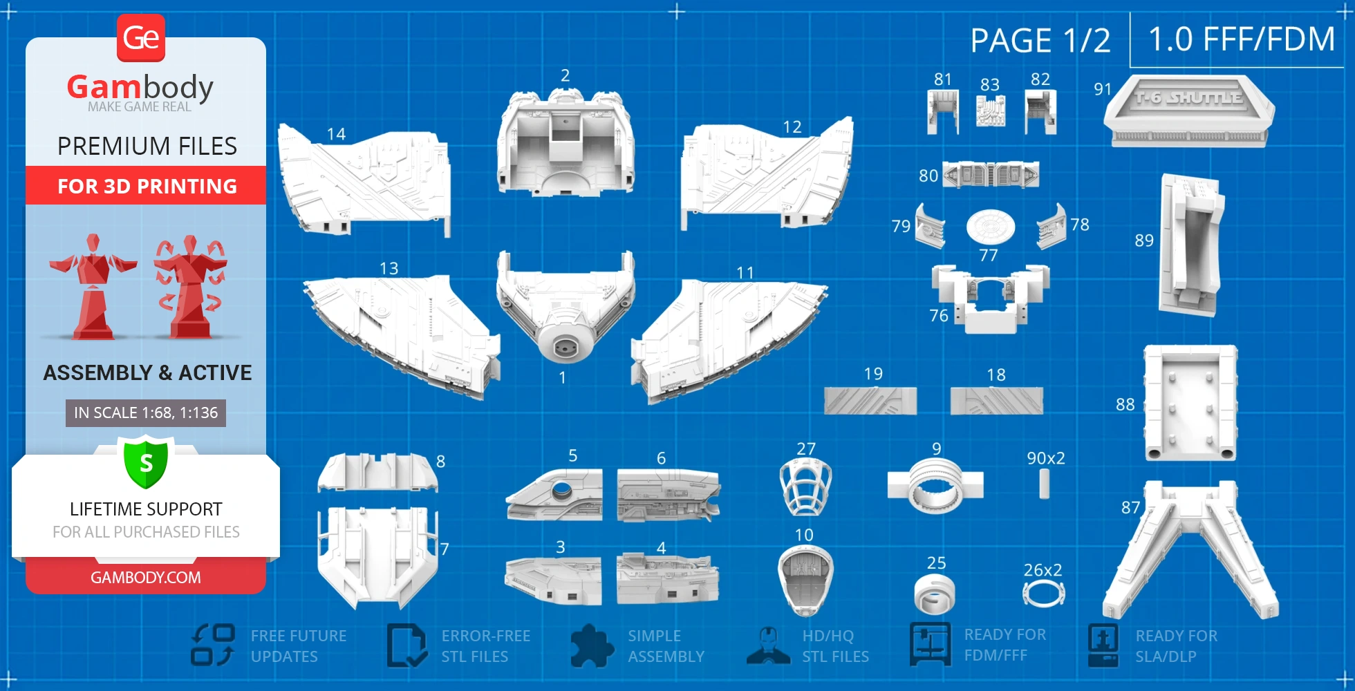
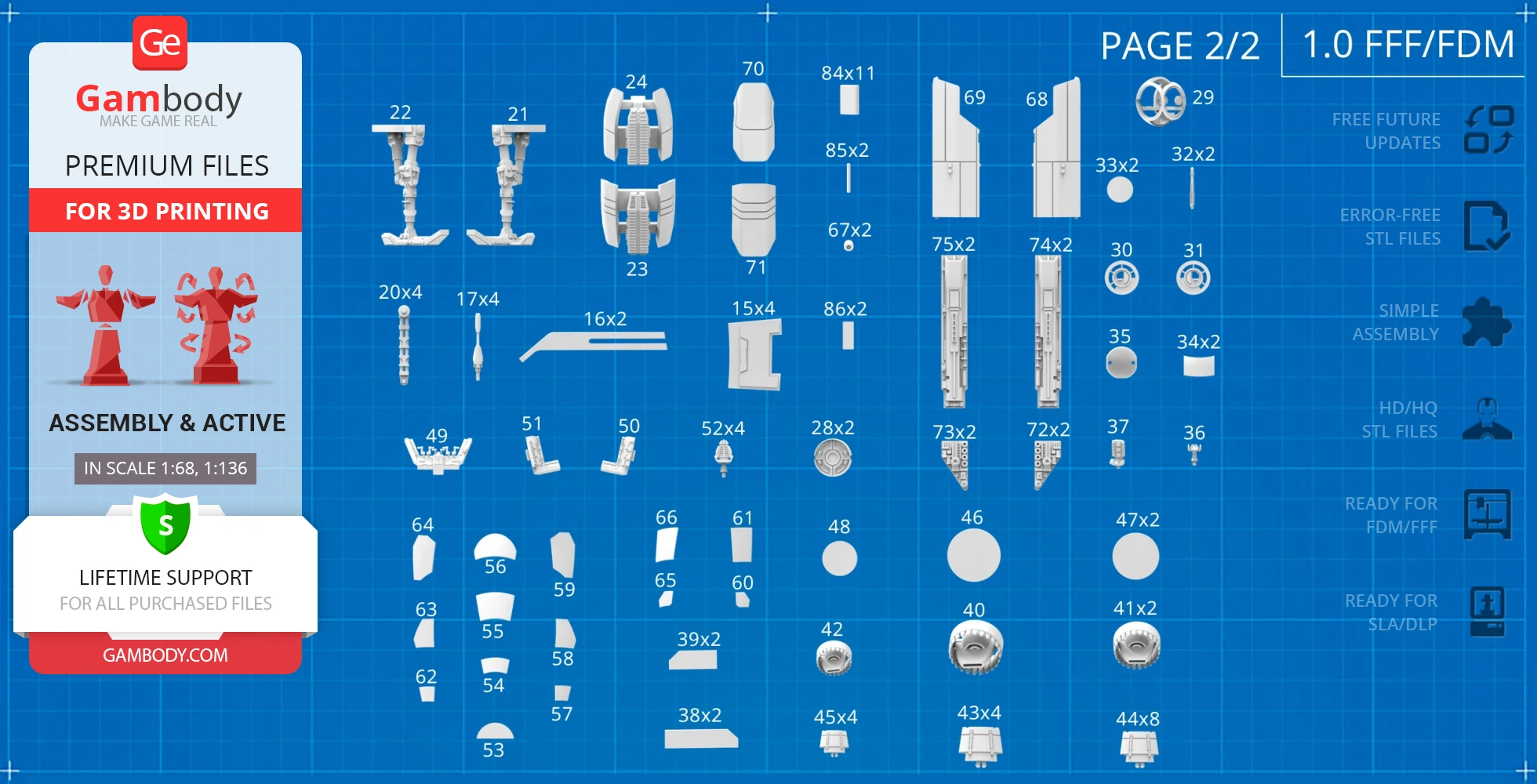
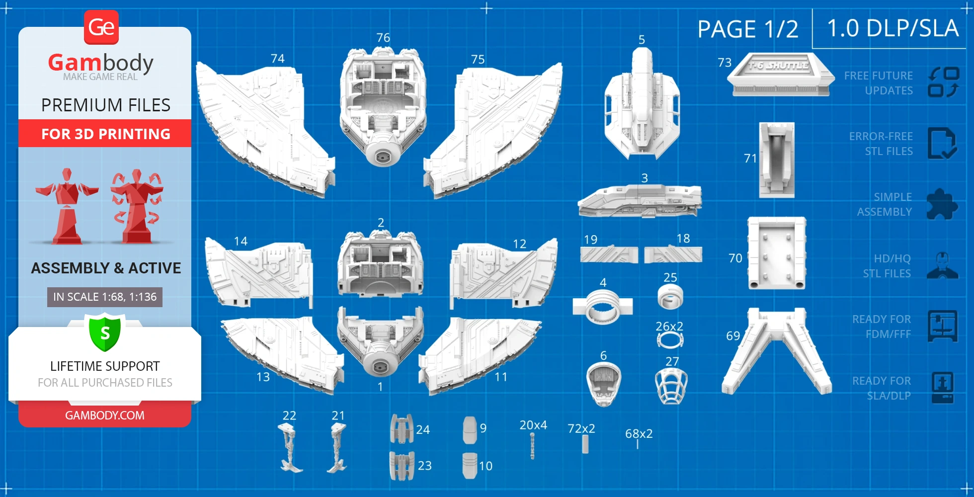
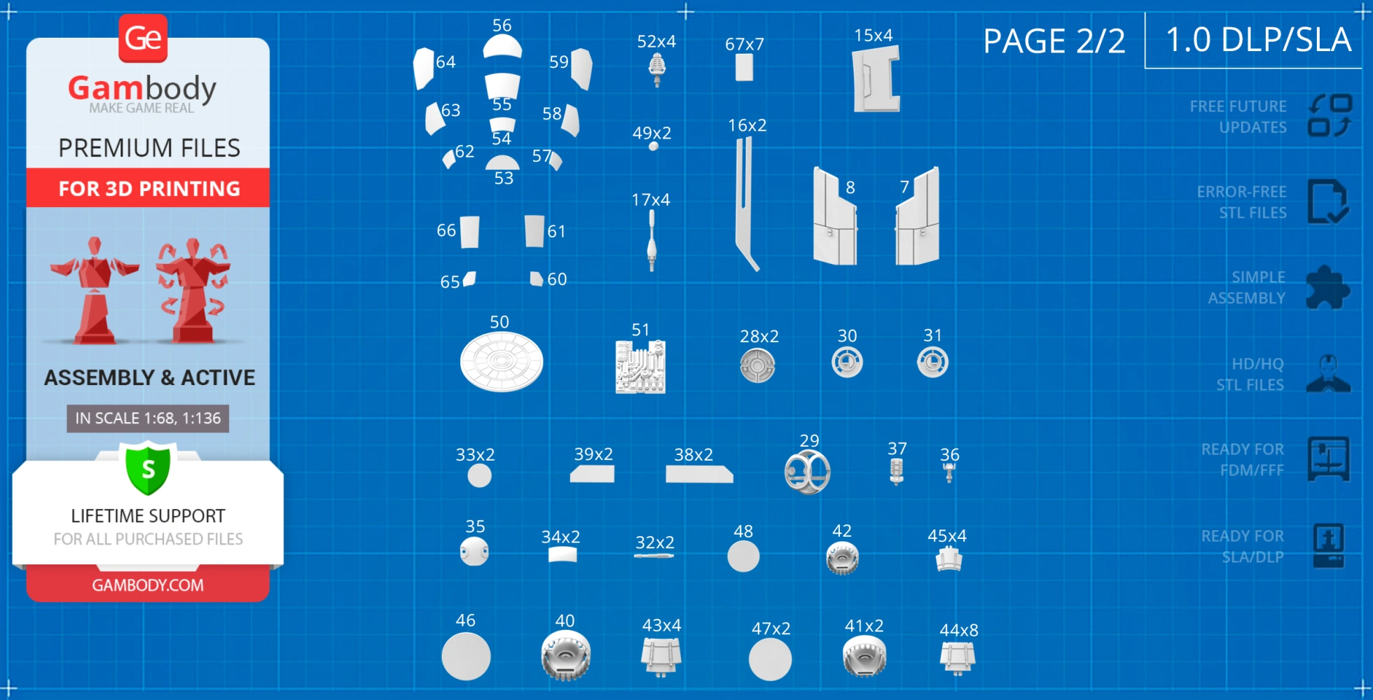
- STL files of high-poly Ahsoka Tano's T-6 Shuttle model for 3D printing consist of 167 files;
- Sizes for:
- FFF/FDM: 149 mm tall, 490 mm wide, 344 mm deep;
- FFF/FDM on a platform: 513 mm tall, 178 mm wide, 373 mm deep;
- DLP/SLA: 75 mm tall, 245 mm wide, 172 mm deep;
- DLP/SLA on a platform: 256 mm tall, 89 mm wide, 187 mm deep;
- Assembly Manual for FFF/FDM 1.0 and DLP/SLA 1.0 versions in PDF and video formats;
- Detailed settings that we provide as a recommendation for Cura, Bambu Studio, Simplify3D, Slic3r and PrusaSlicer for the best print;
- Full technical support from the Gambody Support Team.
Detailed information about these 3D printer STL files is available in the DESCRIPTION section.
Before printing, take a look at Printing Details for recommended settings and tips to achieve better results.
ABOUT THIS 3D MODEL
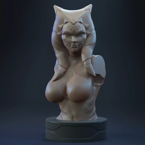
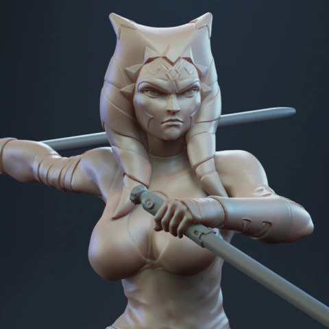
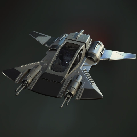
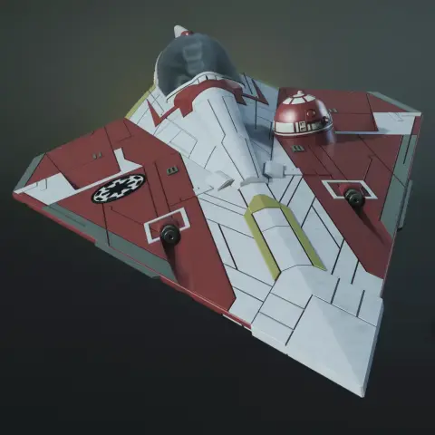
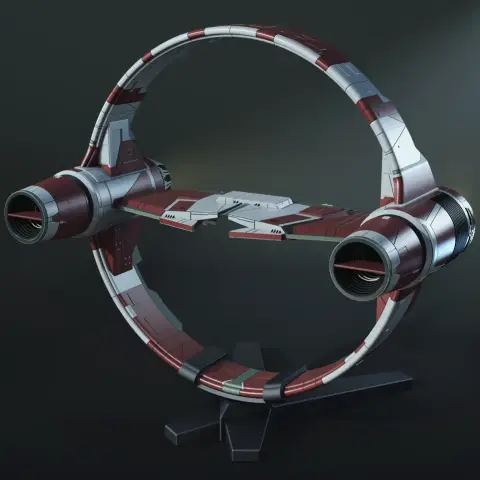
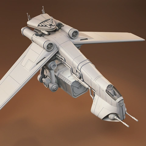
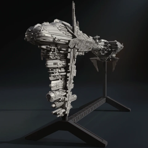
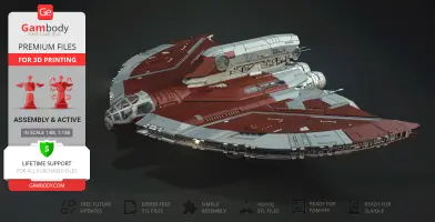
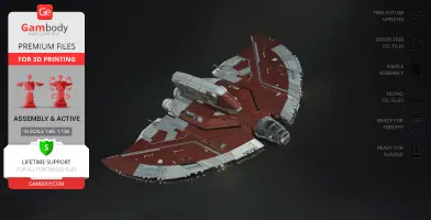
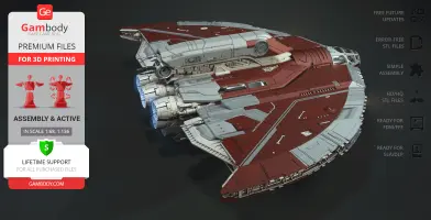
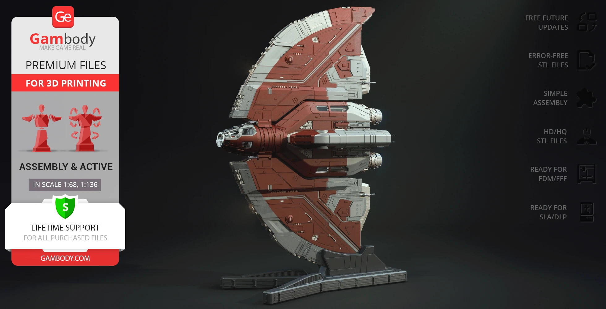
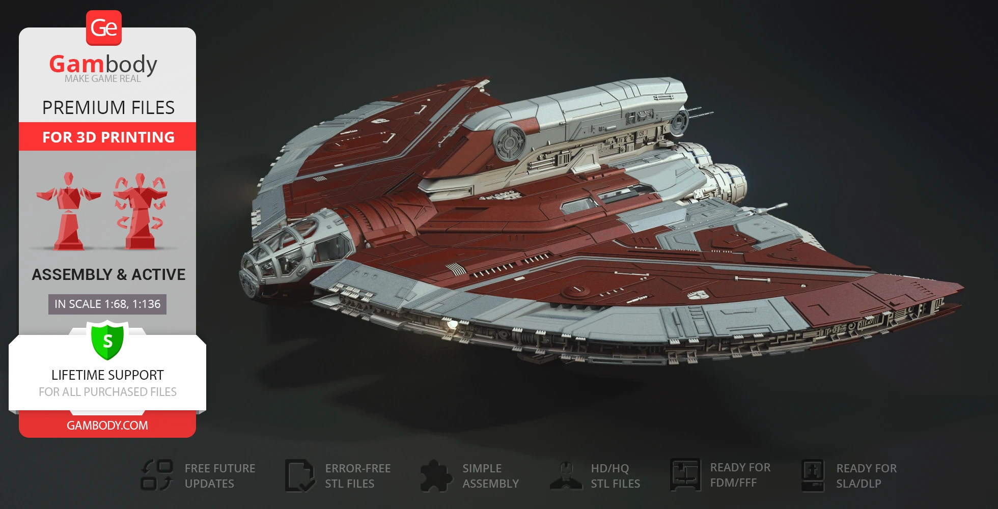
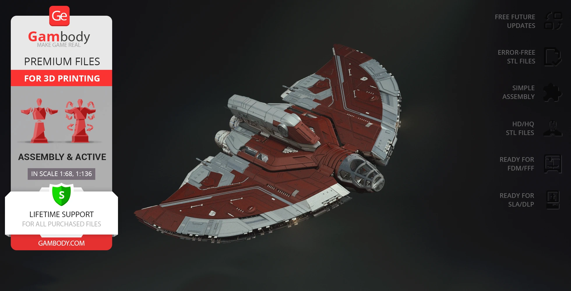
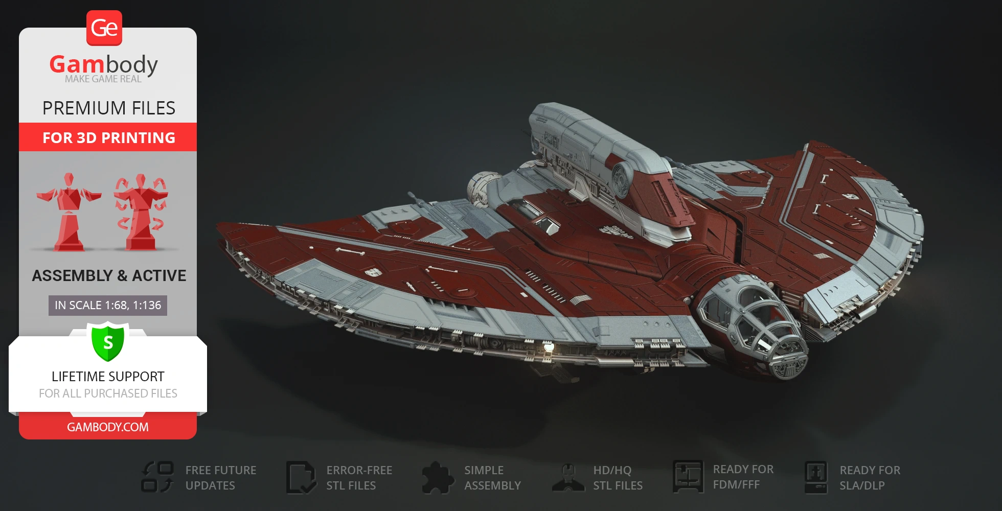
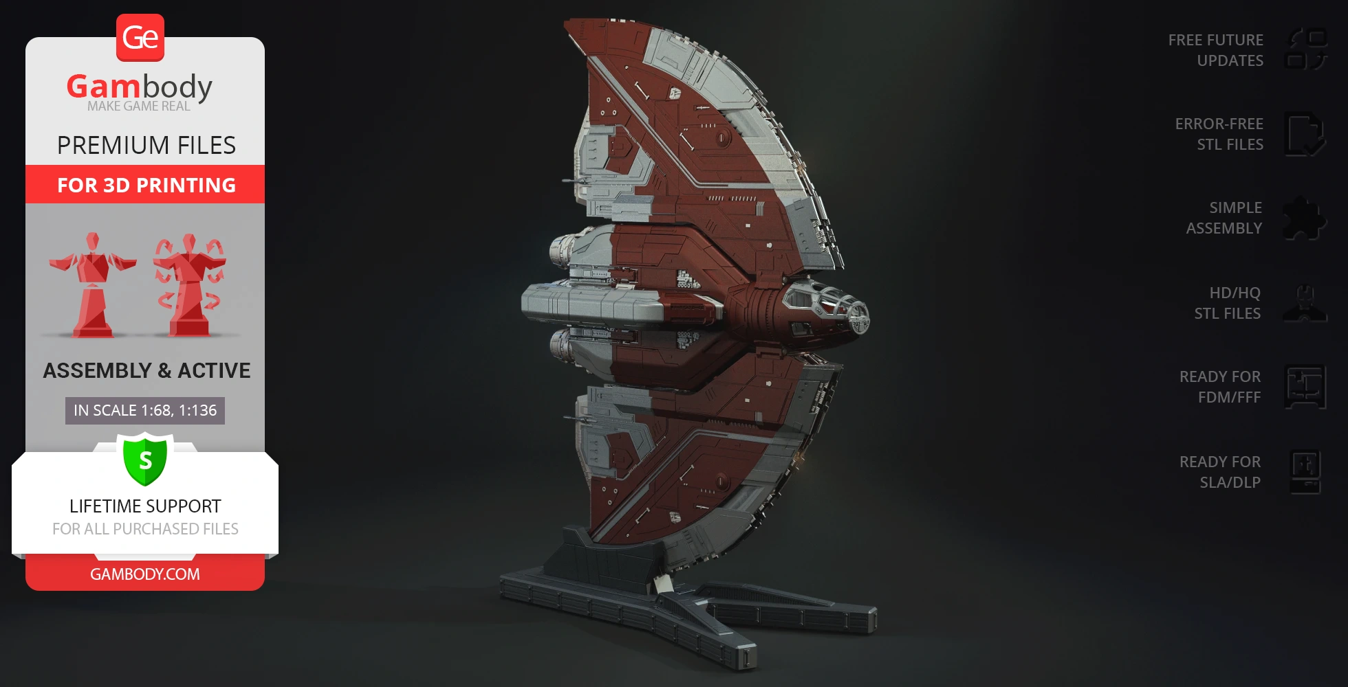
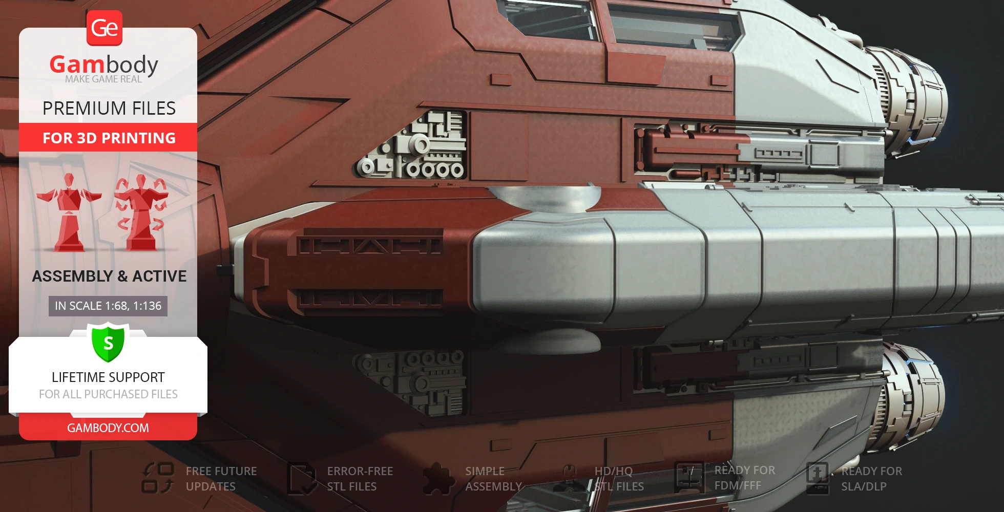
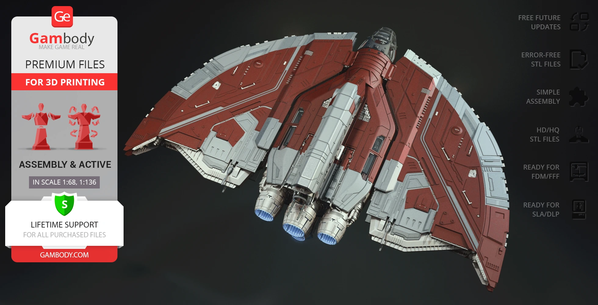
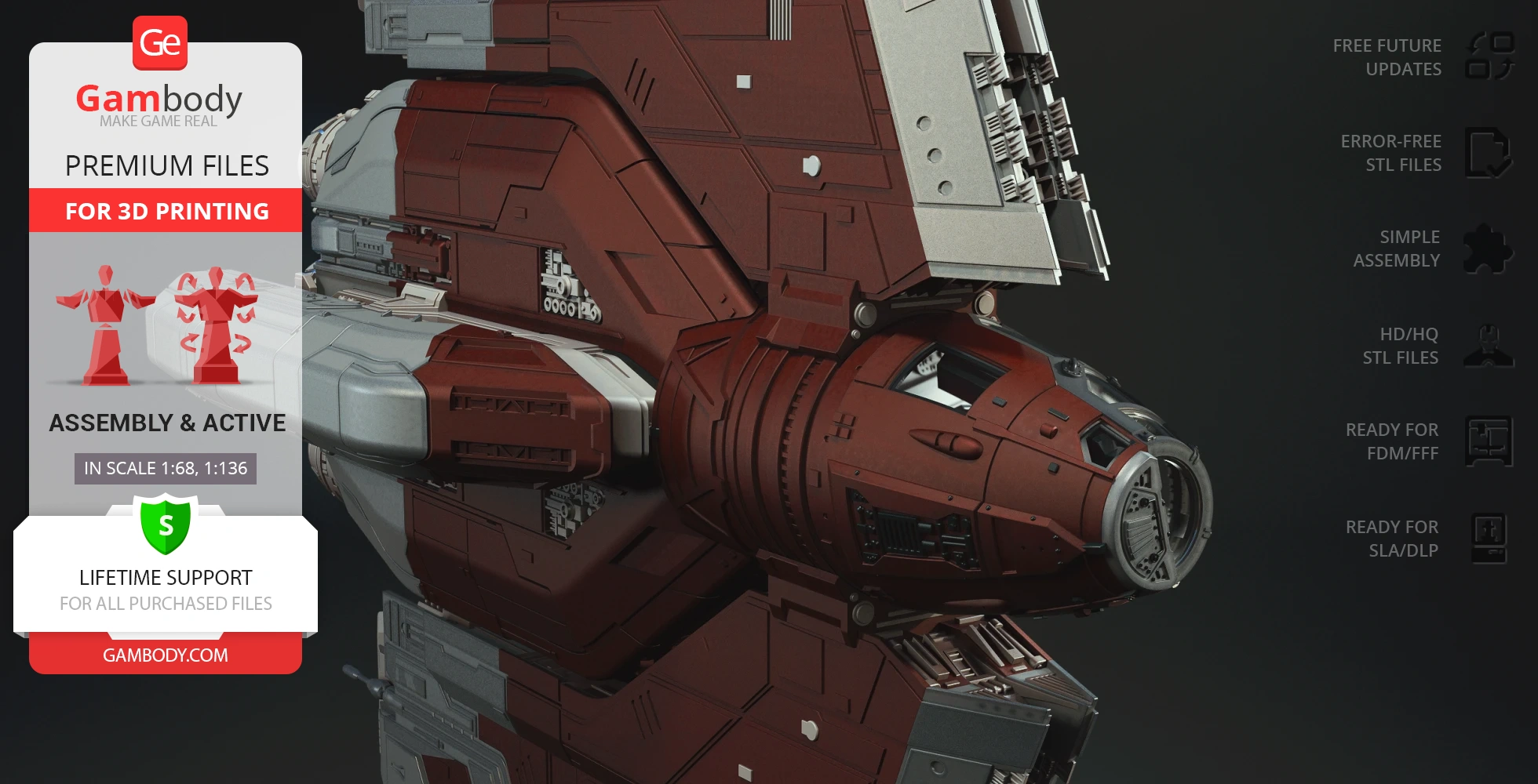
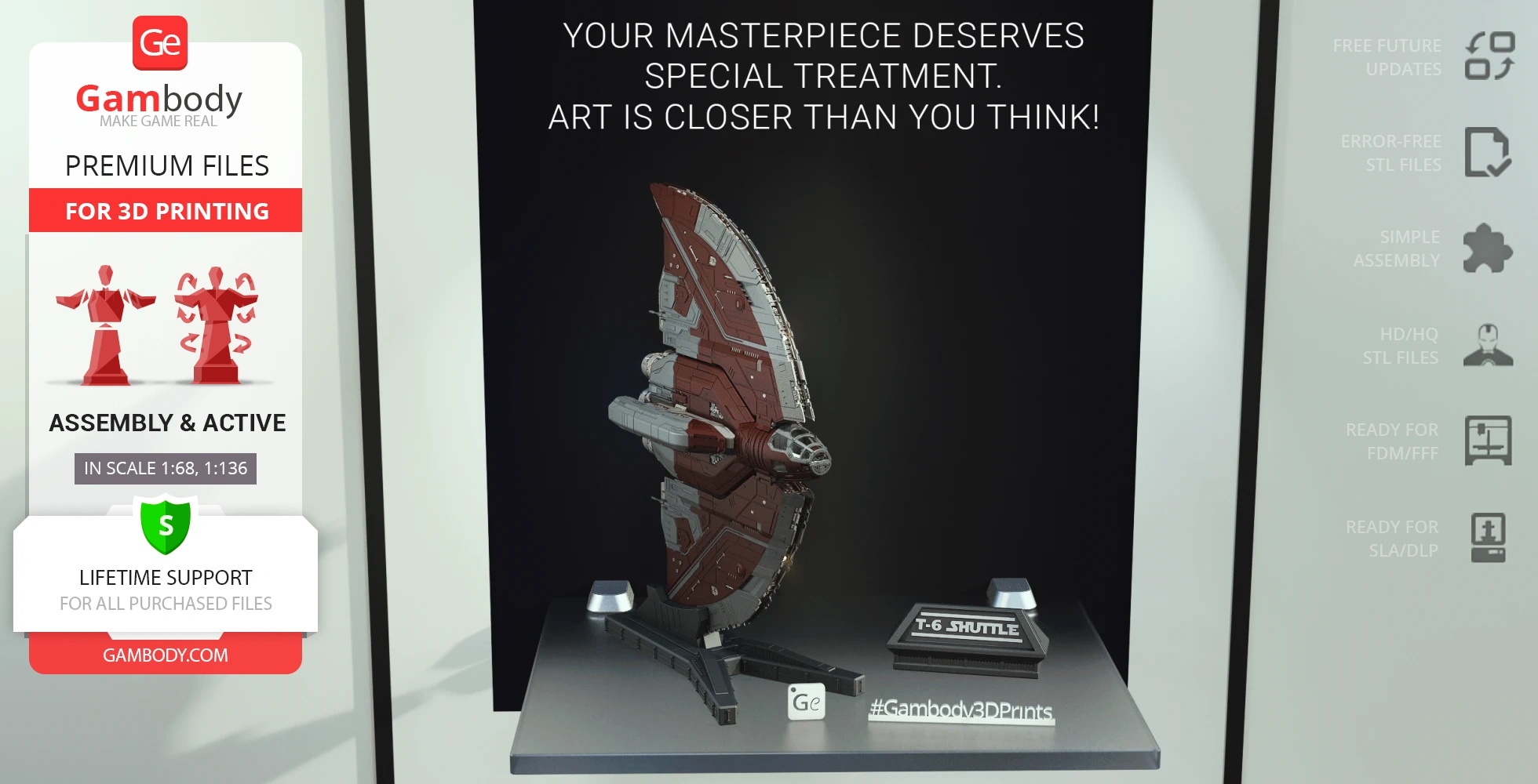
Ahsoka Tano's T-6 Jedi Shuttle is a versatile spacecraft that played a prominent role in the Clone Wars era. This distinctive Star Wars ship served as Ahsoka Tano's personal transport during her time after leaving the Jedi Order, proving to be a reliable and agile vehicle for navigating the galaxy. Known for its unique wing configuration and robust design, the T-6 Shuttle is instantly recognizable to Star Wars fans, embodying the spirit of adventure and resilience that defines the Clone Wars narrative. This spacecraft is a must-know vehicle for any enthusiast of the iconic saga, and now you have a chance to bring a piece of this exciting universe into your collection.
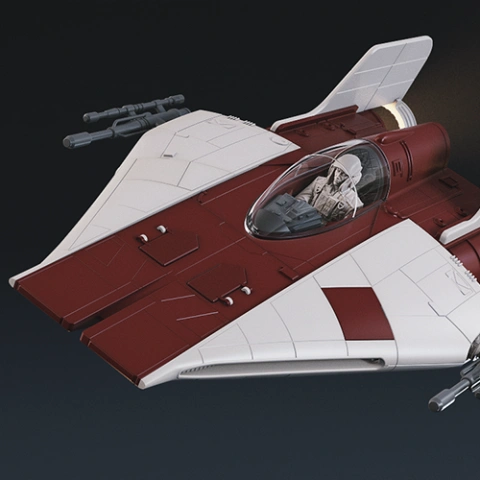
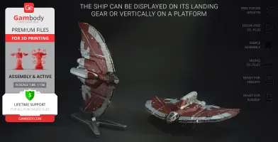
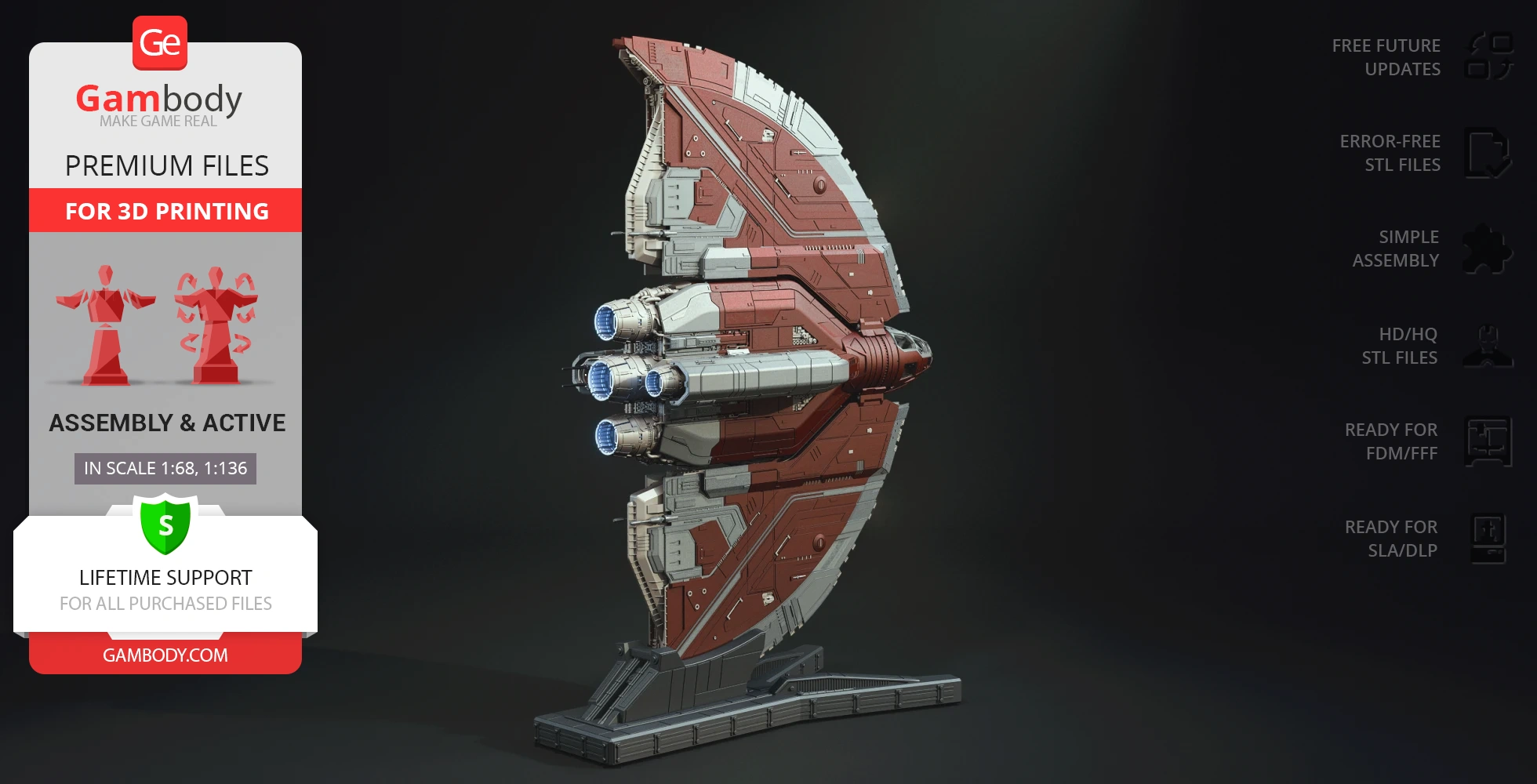
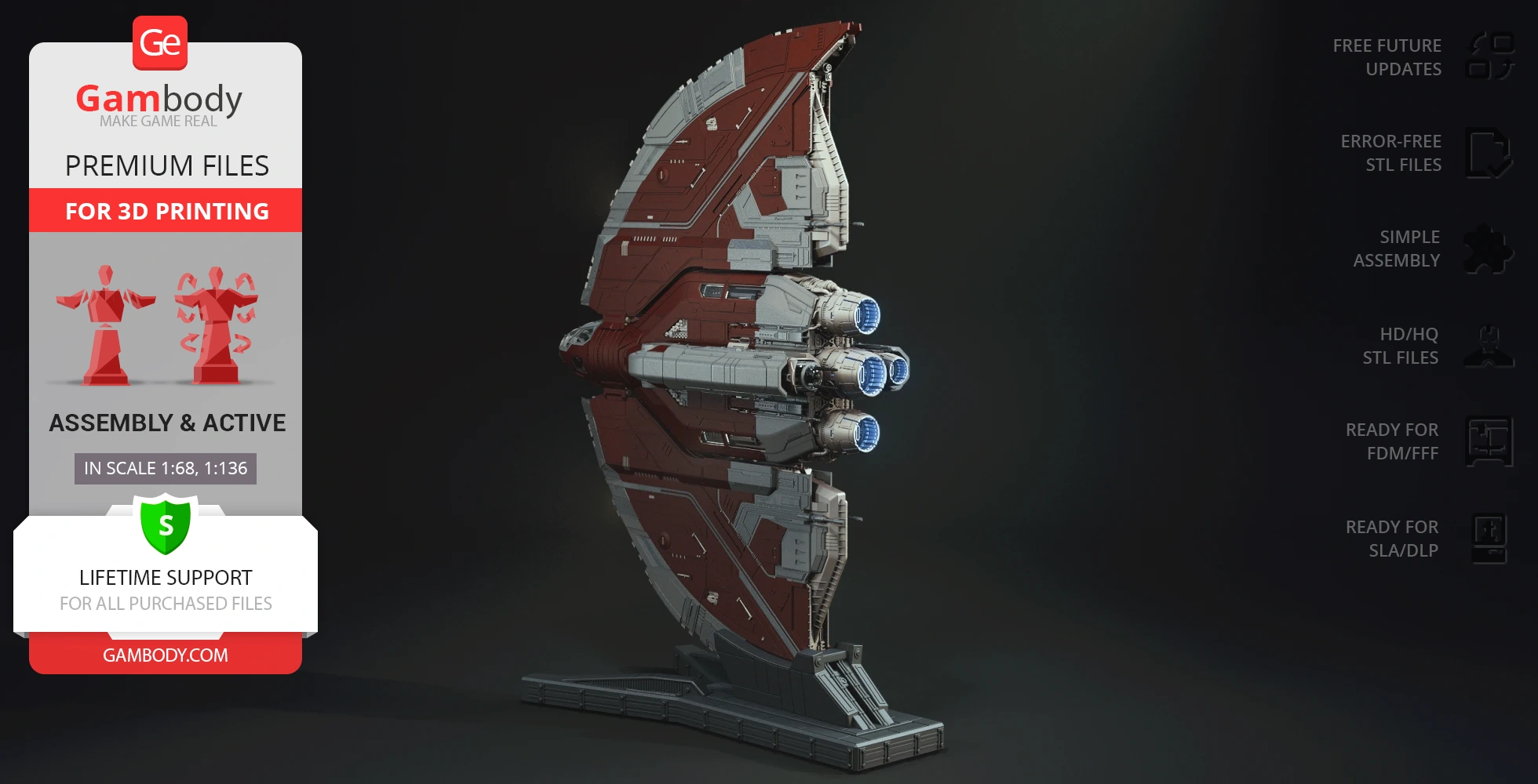
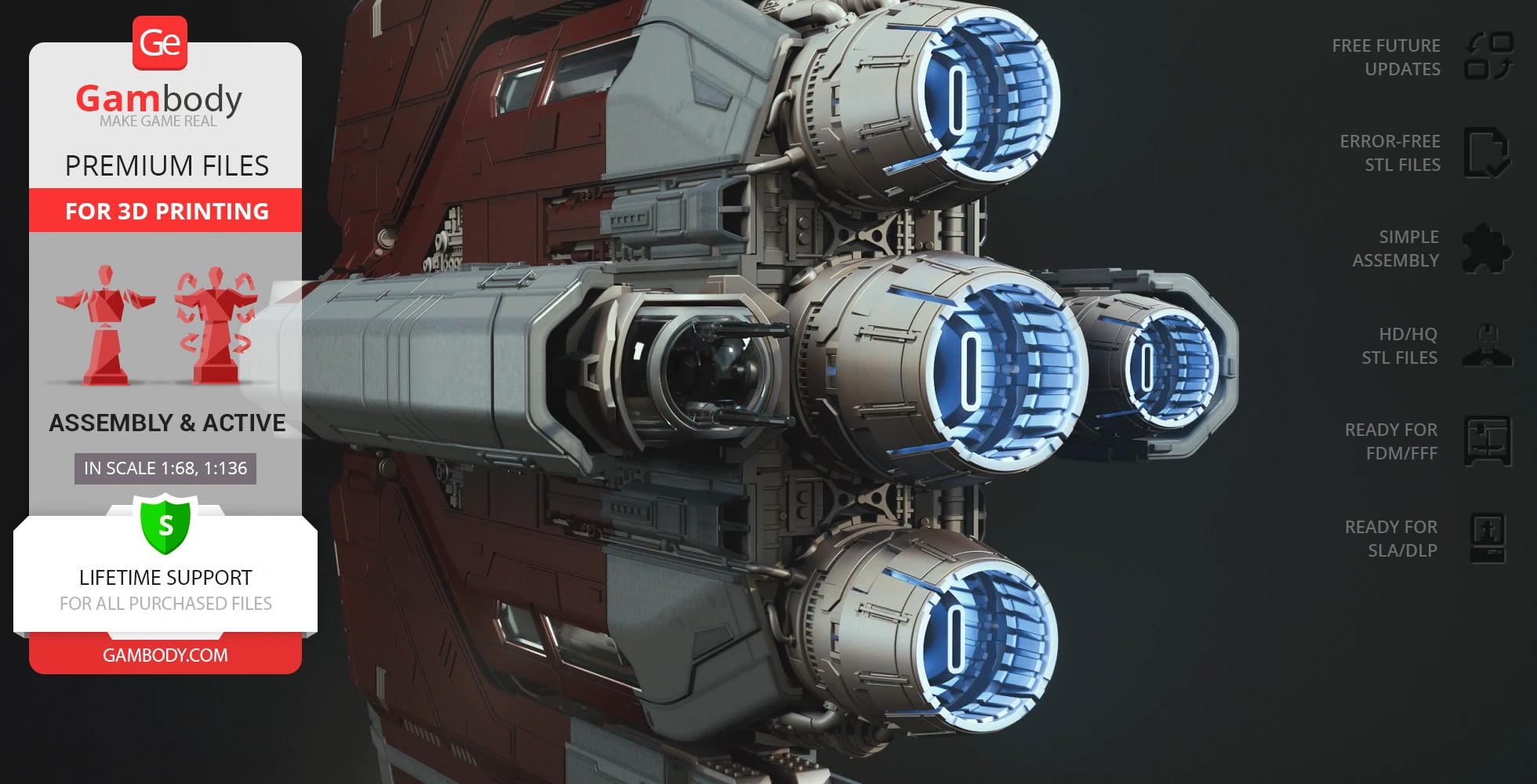
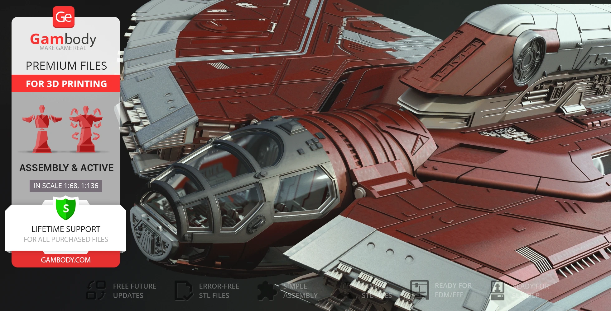
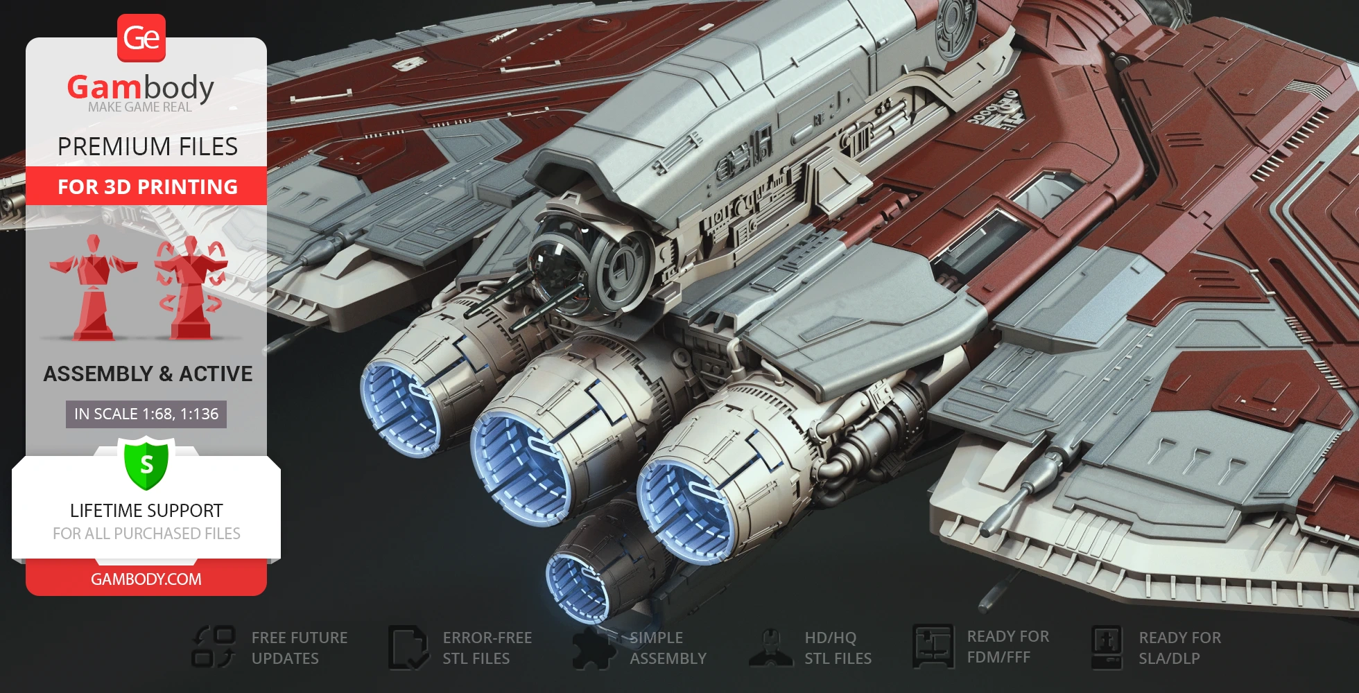
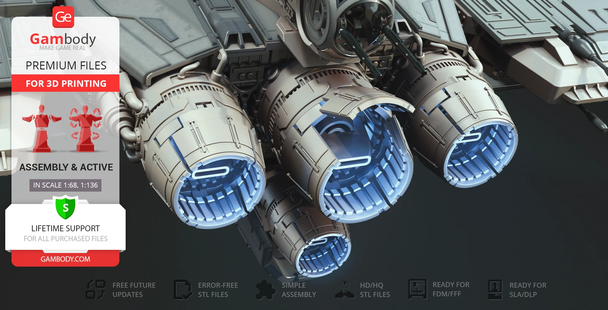
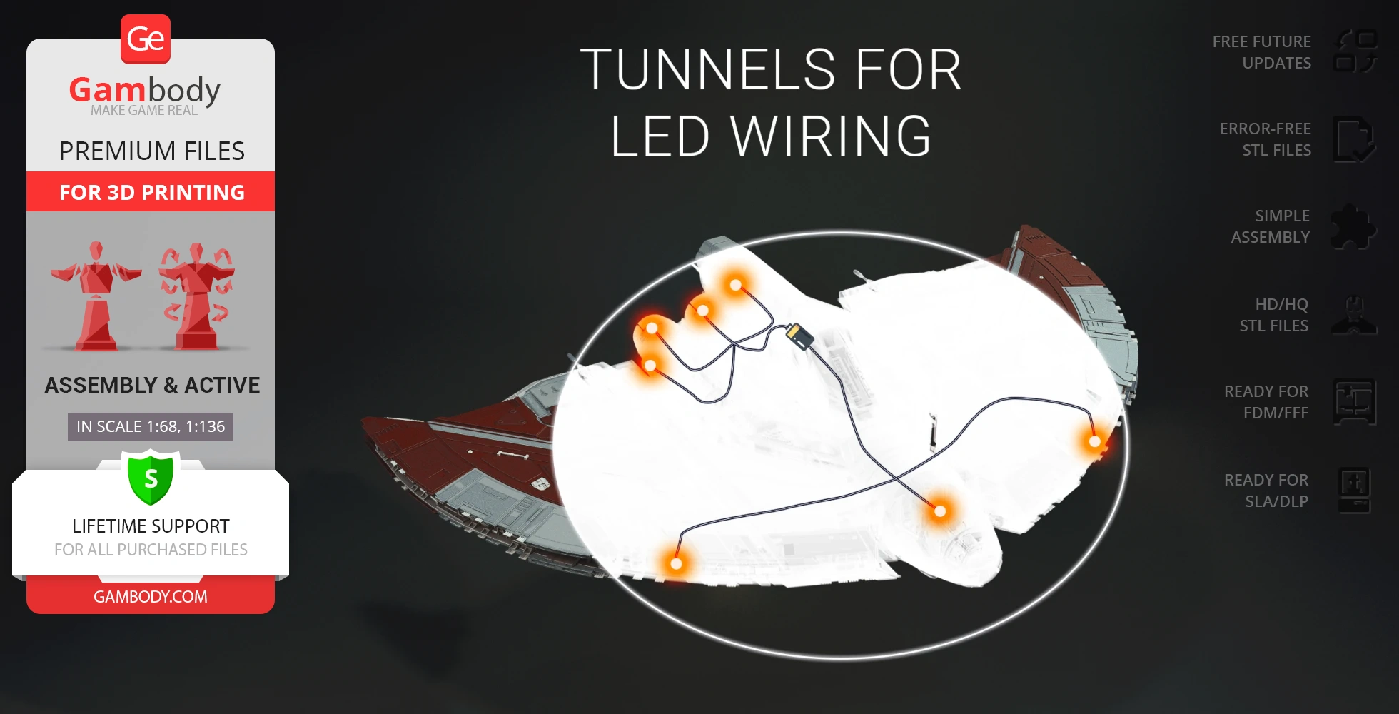
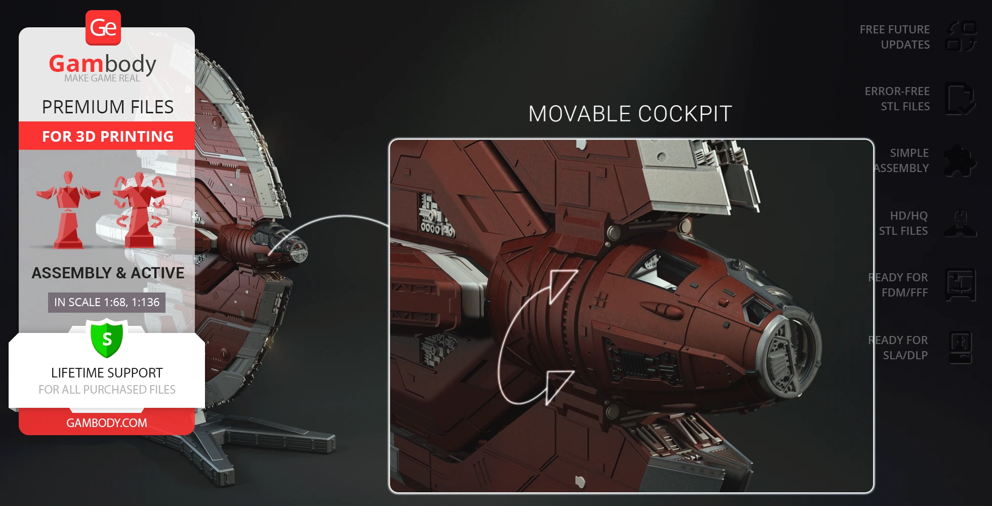
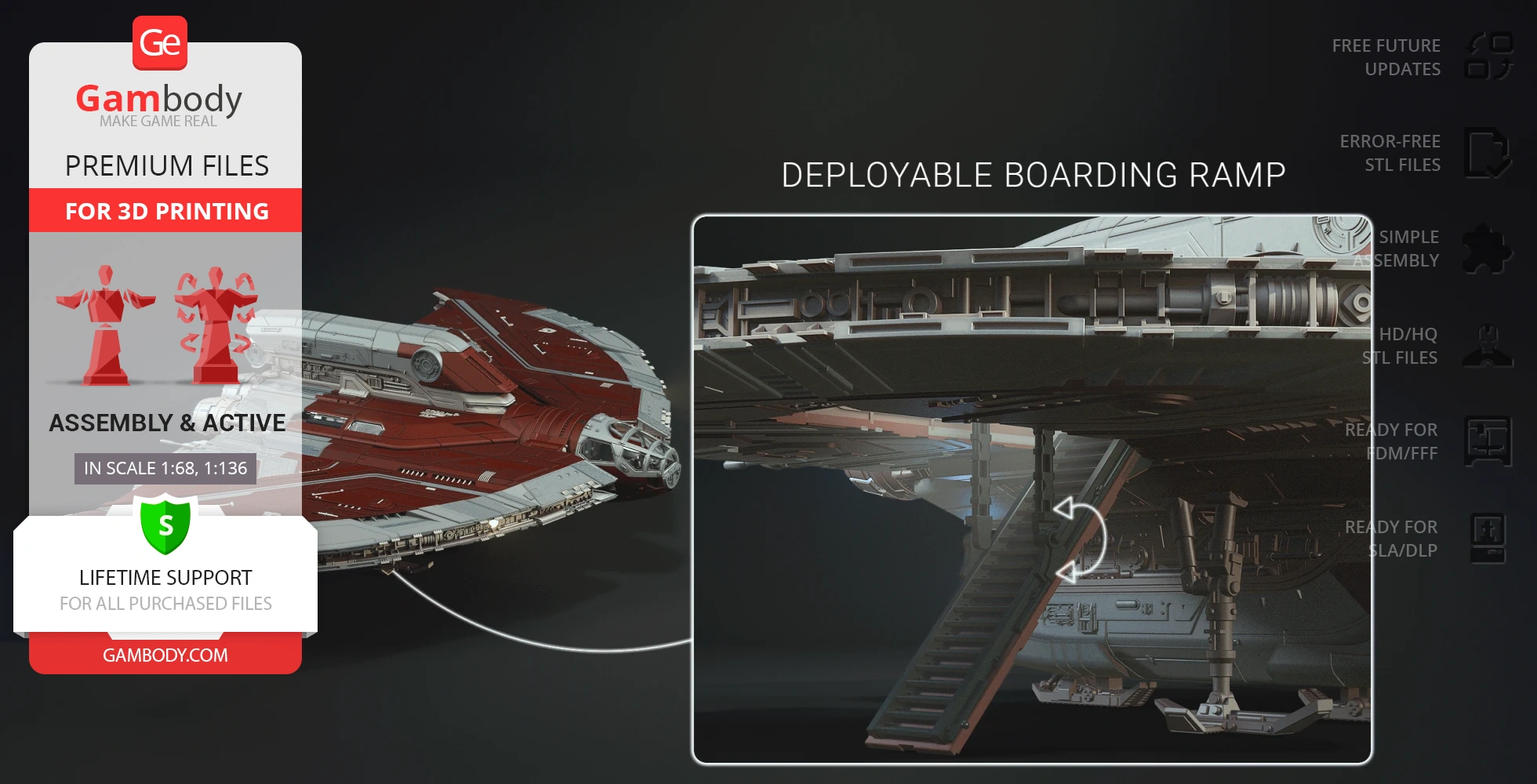
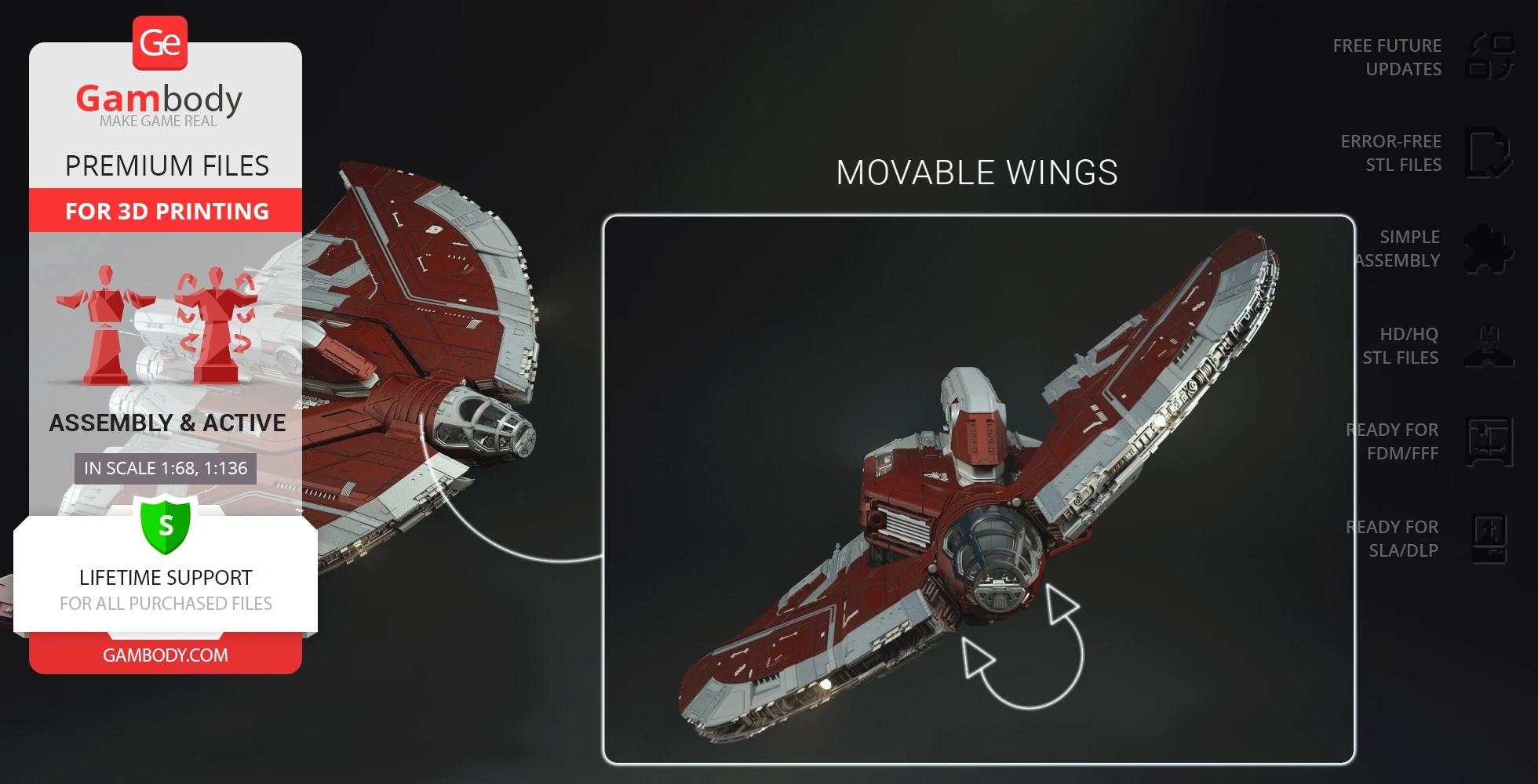
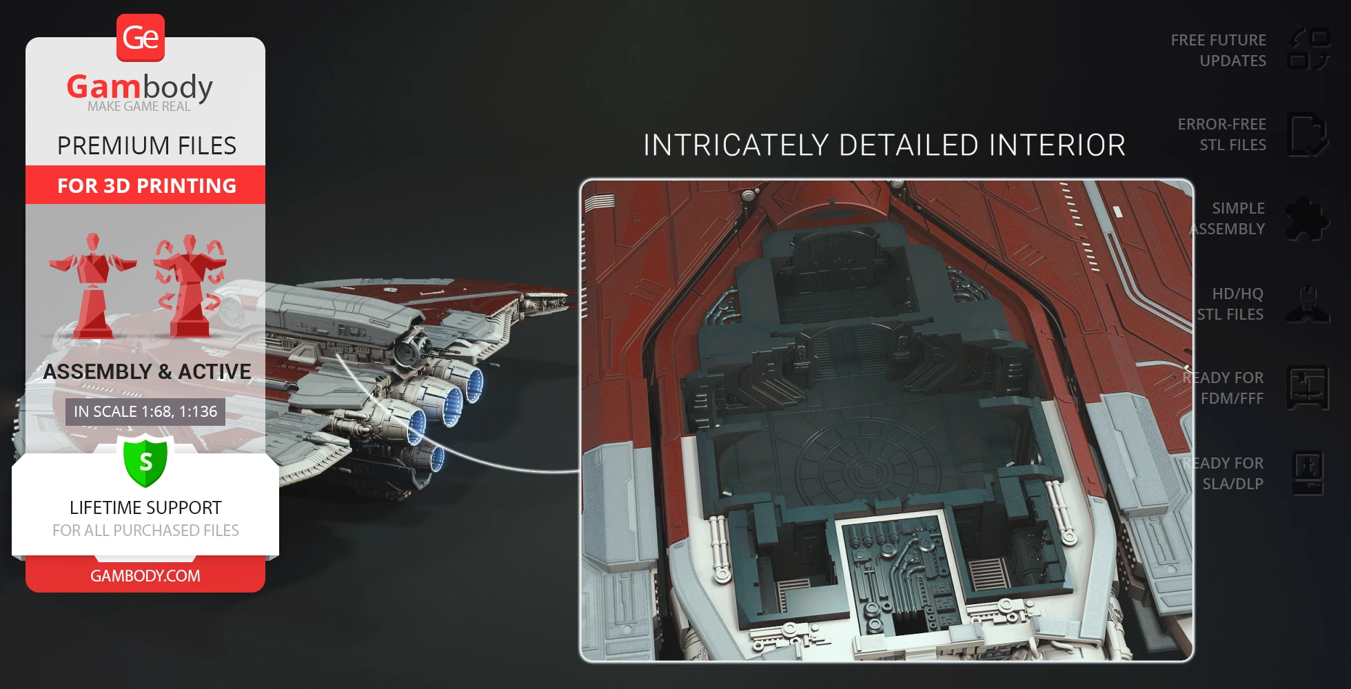
Created by our talented contributing artist, this model boasts numerous features for display and interaction. You can showcase this Star Wars spaceship landed in its two landing gear options or dynamically mounted vertically on a platform. Explore its movable cockpit, deploy the boarding ramp, and adjust the wings to recreate various in-flight or landed configurations. For those seeking an extra touch of realism, tunnels for LED lighting are integrated to illuminate the ship's engines, cockpit, and wings. Get your Star Wars STL files today and experience the joy of building and displaying this exceptional 3D printing design!
ADAPTATION FOR 3D PRINTING
Ahsoka Tano's T-6 Jedi Shuttle 3D printing design is an active assembly model and its moderation and adaptation for different types of 3D printers took the Gambody team 109 hours in total.
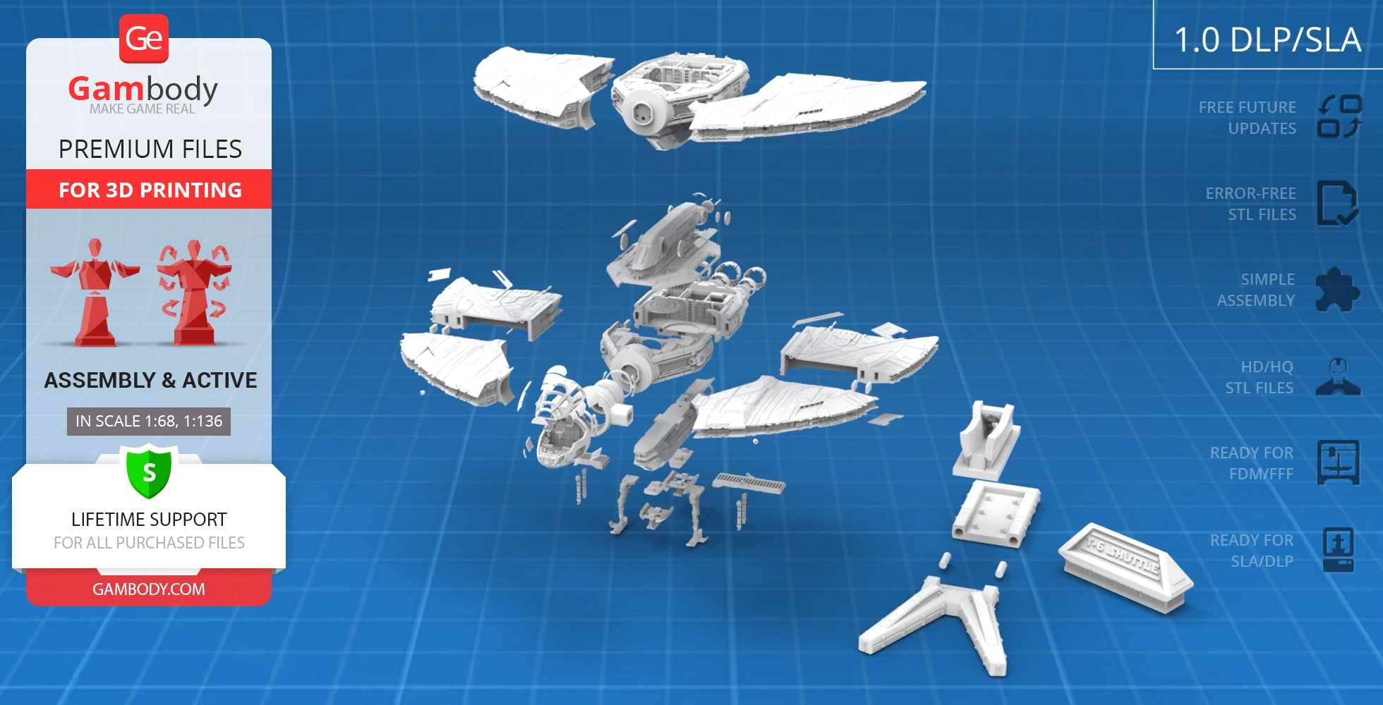
For you to receive the cleanest 3D printing result possible, minimize the amount of filament needed for generated support, and make use of the active elements designed by Gambody Engineers, the spacecraft was divided into convenient assembly parts.
All assembly parts in the 1.0 FFF/FDM version are provided in STL files in recommended positions that were worked out in order to ensure the smoothness of the details’ surfaces after printing and that the 3D printing beginners won’t face difficulties when placing the parts on a build plate. When downloading any model’s file you will also receive “Assembly Manual” for 1.0 FFF/FDM and 1.0 DLP/SLA versions in PDF and video formats. We highly recommend that you get acquainted with the “Assembly Video” and “Assembly Manual” before getting down to the T-6 Jedi Shuttle.
The design is saved in STL files, a format supported by most 3D printers. All STL files for 3D printing have been checked in Netfabb and no errors were shown.
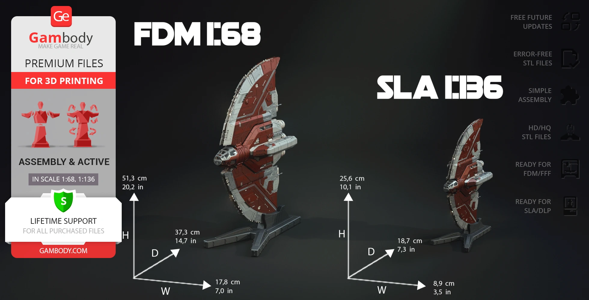
The 3D model’s scale was calculated from the length of the T-6 Jedi Shuttle. The 3D printer design’s chosen scales are 1:68 for the FFF/FDM version and 1:136 for the DLP/SLA version.
VERSIONS’ SPECIFICATIONS
FFF/FDM 1.0 version features:
- Contains 91 parts;
- A printed model on landing gear is 149 mm tall, 490 mm wide, 344 mm deep;
- A printed model on a platform is 513 mm tall, 178 mm wide, 373 mm deep;
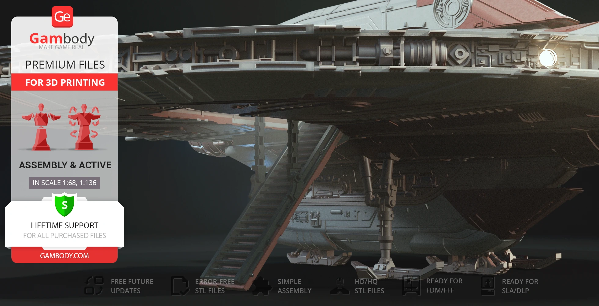
- The ship can be displayed on its landing gear or vertically on a platform;
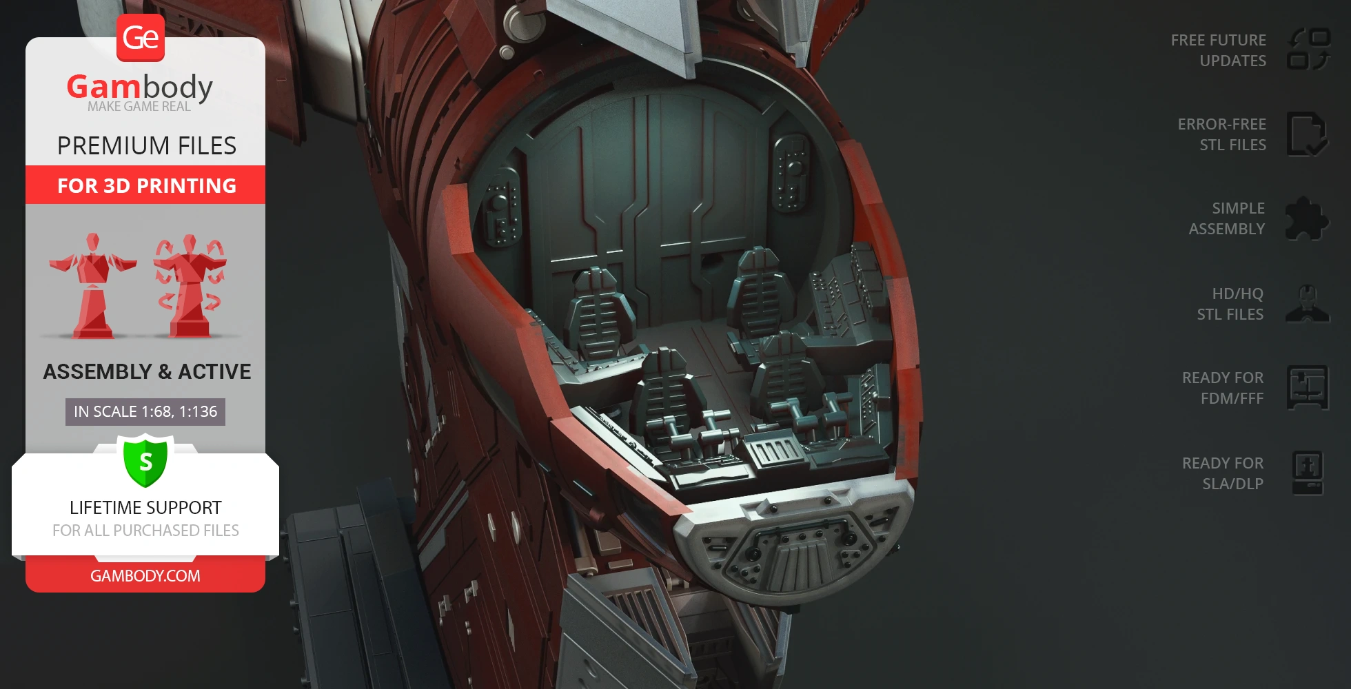
- Movable cockpit;
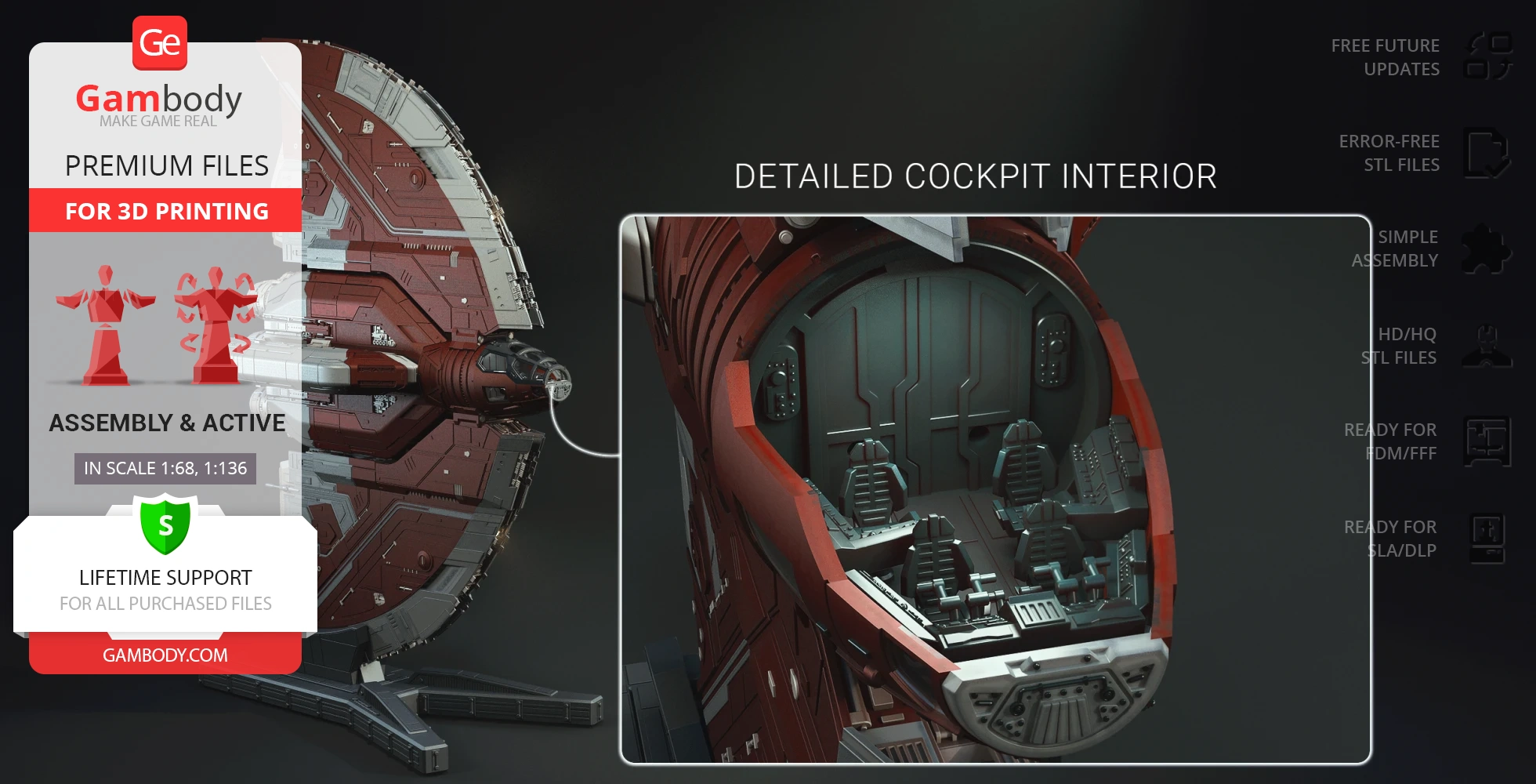
- Detailed cockpit interior;
- Deployable boarding ramp;
- Movable wings;
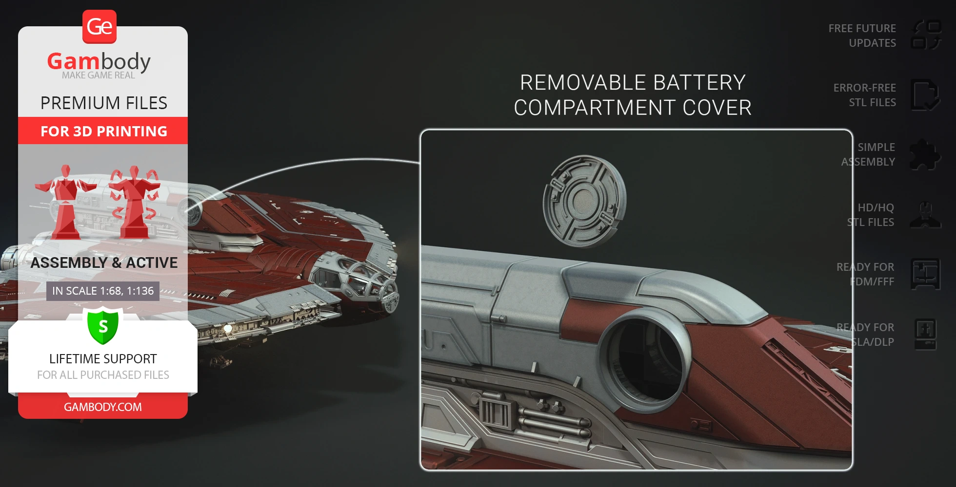
- Removable battery compartment cover;
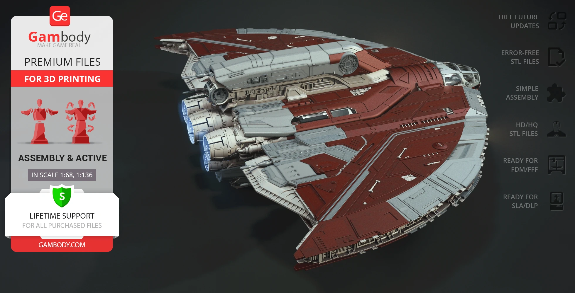
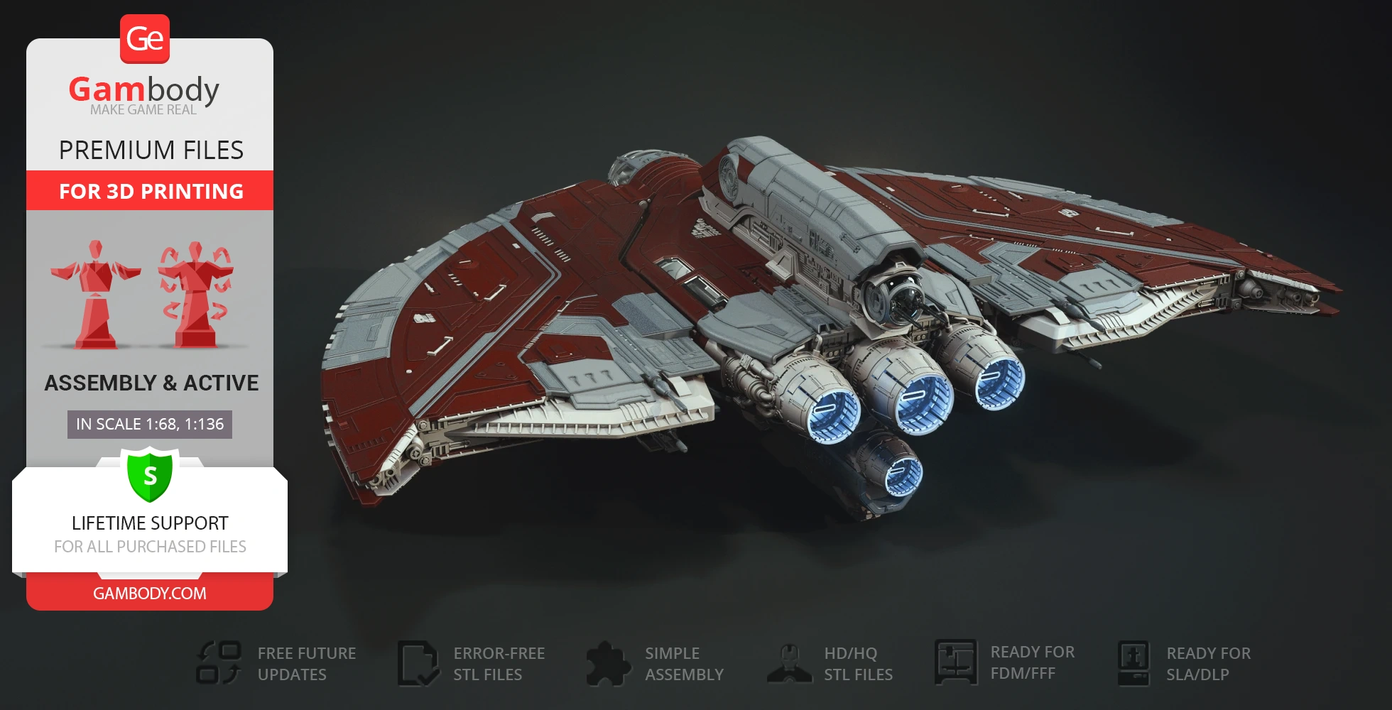
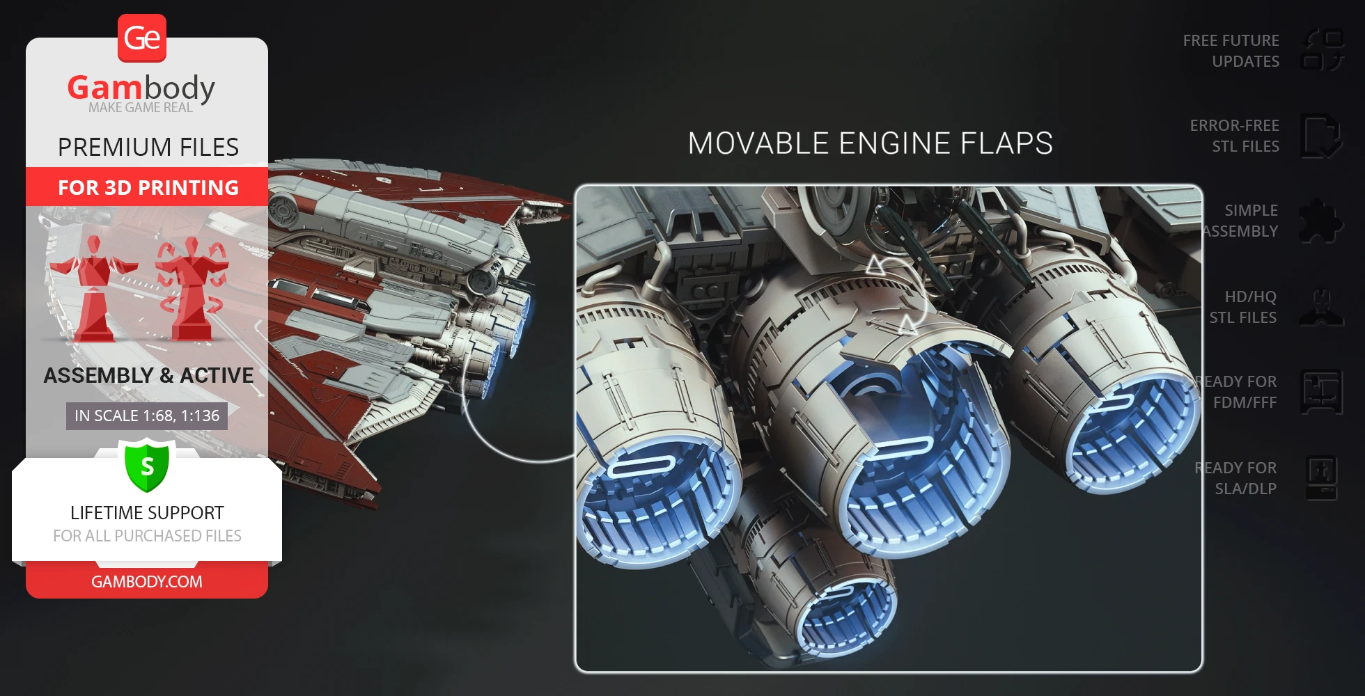
- Movable engine flaps;
- Intricately detailed interior;
- Tunnels for LED wiring to light up the shuttle's engines, cockpit, and wings;
- All parts are divided in such a way that you will print them with the smallest number of support structures.
DLP/SLA 1.0 version features:
- Contains 76 parts;
- A printed model on landing gear is 75 mm tall, 245 mm wide, 172 mm deep;
- A printed model on a platform is 256 mm tall, 89 mm wide, 187 mm deep;
- The ship can be displayed on its landing gear or vertically on a platform;
- Movable cockpit;
- Detailed cockpit interior;
- Deployable boarding ramp;
- Movable wings;
- Removable battery compartment cover;
- Movable engine flaps;
- Intricately detailed interior;
- Tunnels for LED wiring to light up the shuttle's engines, cockpit, and wings;
- All parts are divided in such a way to fit the build plates and to ensure that support structures are generated where needed.
You can get the STL files of Ahsoka Tano's T-6 Jedi Shuttle for 3D printing immediately after the purchase! Just click the green Buy button in the top-right corner of the model’s page. You can pay with PayPal or your credit card.
Watch the tutorial on how to assemble the 3D printed Ahsoka Tano's T-6 Jedi Shuttle model from the provided 3D print files on Gambody YouTube channel.
Also, you may like other Spacecraft3D printing designs.
________
FAQ:
Average customer rating (8 reviews)
4.1
Ratings breakdown
Click a star rating to filter reviews
Overall experience
Level of detail in the model
4.4
Model cut quality and assembly guide
3.9
Clarity and accuracy of the model page
4.1
Level of detail in the model
4
Model cut quality and assembly guide
2
Clarity and accuracy of the model page
1.9
We’ve reviewed this together with our Moderation Team, and our engineers have already prepared updated files for the FDM version (1.0 – Initial). Please re-download the corrected files from the Source Files tab on the model’s page:
_43_engineNozzle_a_X4_FDM
_44_engineNozzle_b_X8_FDM
_45_engineNozzle_c_X4_FDM
The updated file is clearly marked as UPDATED.
Thank you once again for pointing this out. If there’s anything else we can assist you with, please don’t hesitate to reach out – we’re always happy to help.
Level of detail in the model
4.7
Model cut quality and assembly guide
1.6
Clarity and accuracy of the model page
2.6
Currently, this model doesn't include a dedicated pre-supported DLP/SLA version, and it was never stated in the Description of the images that it is. We are sorry for the confusion.
When it comes to file orientation in SLA 3D printing, as a general suggestion, we would recommend that you orient flat surfaces to an incline of up to 45 degrees. By printing a model at an angle, you are reducing the surface area of each layer and decreasing the amount of contact the print has with the tank, which will prevent the warping of the parts.
Also, we recommend that you position your model in a way that the flat surfaces are not parallel or perpendicular to the build plate. When working with projects that require a precise and flush fit, attention should be paid to the technical cut sides and the connecting sides between the parts.
The most important angled sides should be positioned upwards (i.e., towards the tank bottom instead of the build plate) and at a high angle, then they will come out sharp and won't be pulled out of shape. We suggest using a lot of small supports all across the sharp angles instead of rare thick supports. A sufficient net of small supports will even out the pressure applied to the part and will allow it to preserve its shape.
To achieve great results even without the pre-supported files, we recommend referring to the article on the Gambody blog regarding model orientation on DLP/SLA printers. It contains more useful insights for printing with resin and generating supports for your builds:
https://www.gambody.com/blog/best-resin-printing-tips-for-orienting-models-on-sla-dlp-lcd-3d-printers/
For more efficient resin use, we also recommend hollowing out the assembly parts for your projects. While doing so, it's important to ensure that the wall thickness is set to at least 2.2 mm and that the holes are pierced for the parts' orientation so the extra resin can easily drain.
On our marketplace, there are no pre-hollowed or pre-supported versions for hard-surface 3D models like starships, robots, and cars. However, you can find Eco versions of characters' 3D models, which are designed with resin-saving features. You can read more about them here: https://www.gambody.com/blog/dlp-sla-eco-version-of-3d-printing-files-saves-resin/
Additionally, if you're searching for 3D models with pre-supported DLP/SLA versions, feel free to explore the selection available here:
https://www.gambody.com/premium?tag=pre-supported
If you have any additional questions about the 3D model or need assistance with finishing it up, please do not hesitate to reach out to us at support@gambody.com. We will be happy to assist you within the lifetime support programme for the purchased files!
Level of detail in the model
5
Model cut quality and assembly guide
5
Clarity and accuracy of the model page
5
Level of detail in the model
1
Model cut quality and assembly guide
1
Clarity and accuracy of the model page
1
Level of detail in the model
5
Model cut quality and assembly guide
5
Clarity and accuracy of the model page
5
Level of detail in the model
5
Model cut quality and assembly guide
5
Clarity and accuracy of the model page
5
Level of detail in the model
5
Model cut quality and assembly guide
5
Clarity and accuracy of the model page
5
Level of detail in the model
5
Model cut quality and assembly guide
5
Clarity and accuracy of the model page
5
Below you'll find detailed slicing settings for Bambu Studio 2.0+, Orca Slicer 2.0+, UltiMaker Cura 5.0+, PrusaSlicer 2.0+, Slic3r 1.3+, Simplify3D 5.0+ to help you get the best results when printing this model. These settings are optimized specifically for this 3D model, but please note they may need slight adjustments depending on your printer or filament. When in doubt, refer to your printer's user manual.
To avoid printing issues and achieve the best quality, we highly recommend applying the following settings:
For better quality use 0.12 mm layer height, for fast printing use 0.2 mm layer height. For pins and the Ge connectors, use 0.2 layer height.
120-150% of your Layer Height
But you can paint the seam if you want.
You have to calibrate this parameter
You have to calibrate this parameter
You have to calibrate this parameter
For pins and power elements of the structure, such as the vehicle frame, use 3 loop
Disabled for vehicles and enabled for characters
For 0,2 Layer Height
The parameters in this tab vary greatly, it all depends on the quality of your printer. For example, if you have a classic Ender3, stick to the minimum parameters, but if you have a newer printer, for example Anycubic cobra 3 v2, you can select the maximum recommended values
Settings for advanced users, change these parameters only if you have sufficient 3D printing expertise
Enable this parameter if your model requires supports
We also recommend placing and removing supports manually in some places using special button
1-2 loops for more thick support
Top Z distance = 1-1.3 layer Height. If the supports are hard to remove, try increasing this setting by 0.1-0,4 mm
Bottom Z distance = 1-1.3 layer Height. If the supports are hard to remove, try increasing this setting by 0.1-0,4 mm
You have to calibrate this parameter which one is better for your filament
Increase this parameter if the supports are hard to remove from walls
For PLA and PETG filament types
5-8 mm is optional for small prints that have bad adhesion to the build plate
You have to calibrate this parameter
Read the description on your filament roll
Read the description on your filament roll and increase this parameter for fast printers
Read the description on your filament roll and increase this parameter for fast printers
For better quality use 0.12 mm layer height, for fast printing use 0.2 mm layer height. For pins and the Ge connectors, use 0.2 layer height.
120-150% of your Layer Height
But you can paint the seam if you want.
0.01-0.05 You have to calibrate this parameter
0.01-0.05 You have to calibrate this parameter
0.1-0.2 You have to calibrate this parameter
For pins and power elements of the structure, such as the vehicle frame, use 3 loop
Disabled for vehicles and ships, enabled for characters
For 0,2 Layer Height
For 0,2 Layer Height
The parameters in this tab vary greatly, it all depends on the quality of your printer. For example, if you have a classic Ender3, stick to the minimum parameters, but if you have a newer printer, for example, Anycubic Kobra 3 Or Bambulab A1, you can select the maximum recommended values.
Settings for advanced users, change these parameters only if you have sufficient 3D printing expertise
Enable this parameter if your model requires supports
We also recommend placing and removing supports manually in some places using special button
Top Z distance = 1-1.3 layer Height. If the supports are hard to remove, try increasing this setting by 0.1-0,4 mm
Bottom Z distance = 1-1.3 layer Height. If the supports are hard to remove, try increasing this setting by 0.1-0,4 mm
Increase this parameter if the supports are hard to remove from walls
For PLA and PETG filament types
5-8 mm is optional for small prints that have bad adhesion to the build plate
Read the description on your filament roll
Read the description on your filament roll and increase this parameter for fast printers
You have to calibrate this parameter
Read the description on your filament roll and increase this parameter for fast printers
Read the description on your filament roll
This field is filled in according to your printer specifications when you add it to the slicer.
You can add custom G-code here for the start and end of the print. However, be careful - this is for advanced users only!
You have to calibrate your printer using Ge retraction test models
Retraction Length: For direct-drive setups use 0.5 mm to 2.5 mm; for Bowden extruders use 5 to 7 mm
This is how fast the filament is pulled back—40-60 mm/s for direct drive and 30-50 mm/s for Bowden setups.
You have to calibrate this parameter: Reduce it until the printer starts to hit the parts with the nozzle during printing, then increase it by 0.2.
For better quality use 0.12 mm layer height, for fast printing use 0.2 mm layer height. For pins and the Ge connectors, use 0.2 layer height.
120-150% of your Layer Height
To increase the strength of the print parts, use wall line count: 3
For pins and connectors use 50% Infill
These parameters are for standard PLA plastic. If you are using a different type of plastic, check the printing temperature recommended by the manufacturer. Also, read the description on your filament spool. For fast printers, add +30 °C to the current parameters.
The parameters in this tab vary greatly, it all depends on the quality of your printer. For example, if you have a classic Ender3, stick to the minimum parameters, but if you have a newer printer, for example Anycubic cobra 3 v3, you can select the maximum recommended values
Settings for advanced users, change these parameters only if you have sufficient 3D printing expertise.
You need to calibrate this parameter using Gambody test models. These values are average values for a Direct Drive extruder; for a Bowden extruder, the values should be increased.
You need to calibrate this parameter using Gambody test models. These values are average values for a Direct Drive extruder; for a Bowden extruder, the values should be increased.
Use this value other than 0 if your nozzle catches on the internal infill during travel moves. Try to keep this value as low as possible in height.
Use normal supports to support large, straight surfaces (most mechanical or technical parts).
You have to calibrate this parameter according to the capabilities of your printer and your filament, using a Gambody test models.
Use 1 instead of 0 if your supports are thin and tall. They will be harder to remove, but much stronger.
Top Z distance = 1-1.3 layer Height. If the supports are hard to remove, try increasing this setting by 0.1-0,4 mm
Increase this parameter if the supports are hard to remove from walls
Use tree supports to support complex objects, such as characters.
You have to calibrate this parameter according to the capabilities of your printer and your filament, using a Gambody test models.
Top Z distance = 1-1.3 layer Height. If the supports are hard to remove, try increasing this setting by 0.1-0,4 mm
Increase this parameter if the supports are hard to remove from walls
Use a skirt for all parts when printing on outdated printers.
Use a brim when printing thin but tall parts, as well as parts with a small bed adhesion area.
For better quality use 0.12 mm layer height, for fast printing use 0.2 mm layer height. For pins and the Ge connectors, use 0.2 layer height.
120-150% of your Layer Height
for 0.2 Layer Height
But you can paint the seam if you want.
(for PLA and PETG)
(5-8 mm is optional for small prints that have bad adhesion to the build plate)
Enable this parameter if your model requires supports
(45-50 degree)You have to calibrate this parameter according to the capabilities of your printer
and your filament, using a Gambody test models.
Top contact Z distance = 1-1.3 layer Height. If the supports are hard to remove, try
increasing this setting by 0.1-0,4 mm
Top contact Z distance = 1-1.3 layer Height. If the supports are hard to remove, try
increasing this setting by 0.1-0,4 mm
Increase this parameter if the supports are hard to remove from walls
The parameters in this tab vary greatly, it all depends on the quality of your printer. For example, if you have a classic Ender3, stick to the minimum parameters, but if you have a newer printer, for example Anycubic cobra 3 v3, you can select the maximum recommended values
Settings for advanced users, change these parameters only if you have sufficient 3D printing expertise. Use the minimum value for outdated printers without acceleration calibration, and the maximum value for modern printers if you need it.
These settings only work for 3D printers with multiple extruders
You can try setting all parameters in this section, except the First layer, to values between 0.75% of your nozzle diameter and 1.25% of your nozzle diameter. Adjusting them will help you work out the optimal parameters for the best quality for your print. As for the First layer, you can set it to 150% of the diameter of your nozzle for better adhesion to the build plate (for a nozzle with a diameter of 0.4 mm, the First layer extrusion width can be from 0.3 mm to 0.5 mm)
For better printing quality you have to calibrate this parameter using Gambody test model.
Check your filament manufacturer's temperature recommendations on the spool.
Cooling parameters depends on the material you use for printing.
*for PLA
For better quality use 0.12 mm layer height, for fast printing use 0.2 mm layer height. For pins and the Ge connectors, use 0.2 layer height.
120-150% of your Layer Height
For 0.12 Layer Height
For 0.12 Layer Height
For pins and connectors use 50% Infill
Use skirt for outdated 3d printers
(5-8 mm is optional for small prints that have bad adhesion to the build plate)
Enable this parameter if your model requires supports
(45-60 degree)You have to calibrate this parameter according to the capabilities of your printer and your filament, using a Gambody test models
Contact Z distance = 1-1.3 layer Height. If the supports are hard to remove, try increasing this setting by 0.1-0,4 mm
The parameters in this tab vary greatly, it all depends on the quality of your printer. For example, if you have a classic Ender3, stick to the minimum parameters, but if you have a newer printer, for example Anycubic cobra 3 v3, you can select the maximum recommended values
Settings for advanced users, change these parameters only if you have sufficient 3D printing expertise. Use the minimum value for outdated printers without acceleration calibration, and the maximum value for modern printers if you need it.
You have to calibrate this parameter from 0.9 to 1.1 according to the capabilities of your printer and your filament, using a Gambody test models.
Check your filament manufacturer's temperature recommendations on the spool.
Cooling parameters depends on the material you use for printing.
Calibrate this value if you need to reduce or improve the adhesion between the plastic and the heat bed
Your current nozzle diameter
You need to calibrate this parameter using Gambody test models. These values are average values for a Direct Drive extruder; for a Bowden extruder, the values should be increased.
Your current nozzle diameter
You have to calibrate this parameter using Gambody test models.
You need to calibrate this parameter using Gambody test models. These values are average values for a Direct Drive extruder; for a Bowden extruder, the values should be increased.
For better quality use 0.12 mm layer height, for fast printing use 0.2 mm layer height. For pins and the Ge connectors, use 0.2 layer height.
For 0,2 Layer Height
For 0,2 Layer Height
To increase the strength of the print parts, use Outline Perimeters: 3
You can enable this parameter to print rounded or spherical models, as well as character models.
Use this option only if your parts are too tight. but better calibrate your printer extrusion
Use this option only if your parts are too tight. but better calibrate your printer extrusion
Use 2 and more if you want to create skirt instead brim
1-2 for skirt and 10-20 for brim
Use for wipe nozzle if you need
Use For ABS filament
For pins and connectors use 50% Infill
Top Z distance = 1-1.3 layer Height. If the supports are hard to remove, try increasing this setting by 0.1-0,4 mm
Calibrate your filament and detect optimal temperature for it
Average temperature for PLA filament
The parameters in this tab vary greatly, it all depends on the quality of your printer. For example, if you have a classic Ender3, stick to the minimum parameters, but if you have a newer printer, for example Anycubic cobra 3 v3, you can select the maximum recommended values
Settings for advanced users, change these parameters only if you have sufficient 3D printing expertise.