


Files
3D model format
Stereolithography (.stl)
Total files
Slicer settings
Mesh error check
Netfabb
Support
Lifetime support from Gambody team
Update requests
Available to verified buyers
Model complexity
Advanced: may require tuning print settings or support placement, plus precise fitting, gluing, or sanding.
Model versions
FFF/FDM
Assembly method
not specified
Features
DLP/SLA
Assembly method
not specified
Features
FFF/FDM
Assembly method
not specified
Features
DLP/SLA
Assembly method
not specified
Features
Additional details
Part of diorama
No
Special pack included
No
You will get instant access to the STL files of LAAT/i Gunship 3D Printing Model | Assembly after completing your purchase. Simply add the model to your cart and check out using PayPal, credit or debit card, Apple Pay, Google Pay, Alipay, or other available payment methods.
Watch the assembly video for LAAT/i Gunship 3D Printing Model | Assembly, and explore more tutorials, behind-the-scenes content, 3D printing timelapses, and painting guides on the official Gambody YouTube channel.
This 3D Model consists of files in StereoLithography (.Stl) format that is optimized for 3D printing.
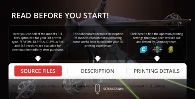
Before printing the files, we strongly recommend reading the PRINTING DETAILS section.
LAAT/i Gunship 3D Printing Model comes in 2 updated and 2 older versions for each 3D printer type (FFF/FDM and DLP/SLA/SLS). Files for each version are available for download after the purchase.
Detailed information about this 3D printing model is available in the DESCRIPTION section.
Before printing, take a look at Printing Details for recommended settings and tips to achieve better results.
ABOUT THIS 3D MODEL
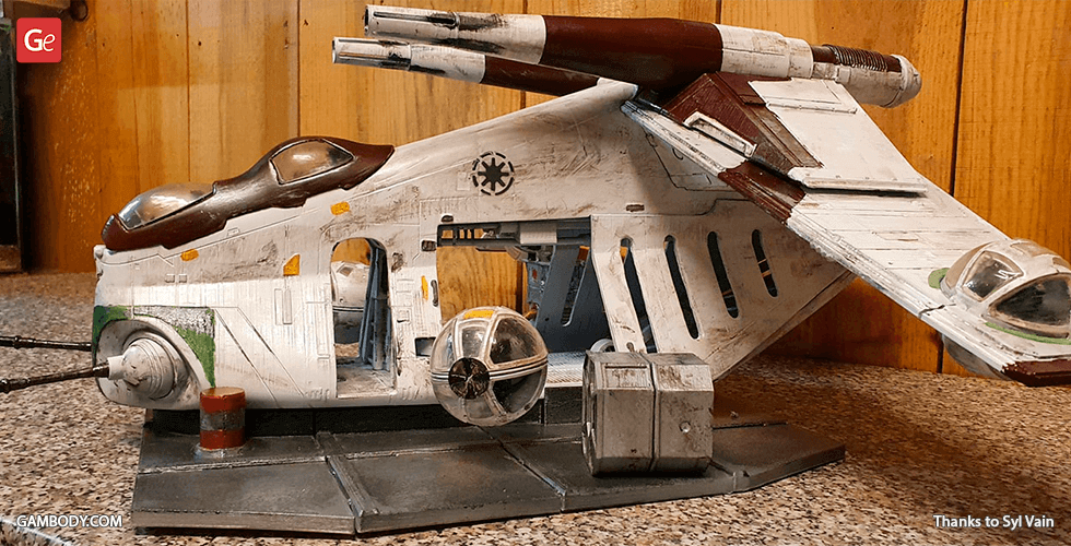
"These gunships fly like butcherbugs and cut into us like Blood Carvers. We must have one."
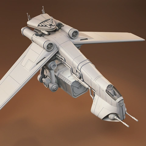
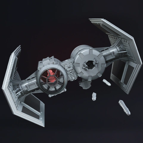
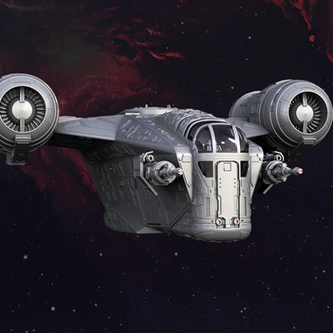
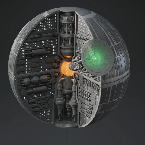
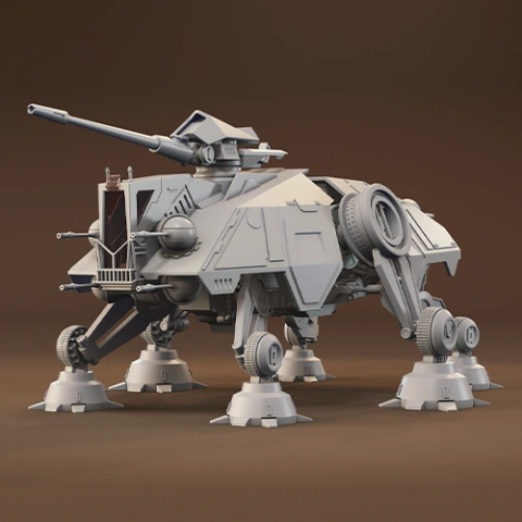
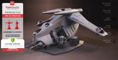
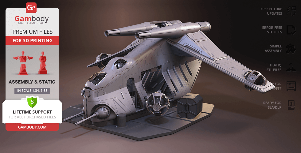
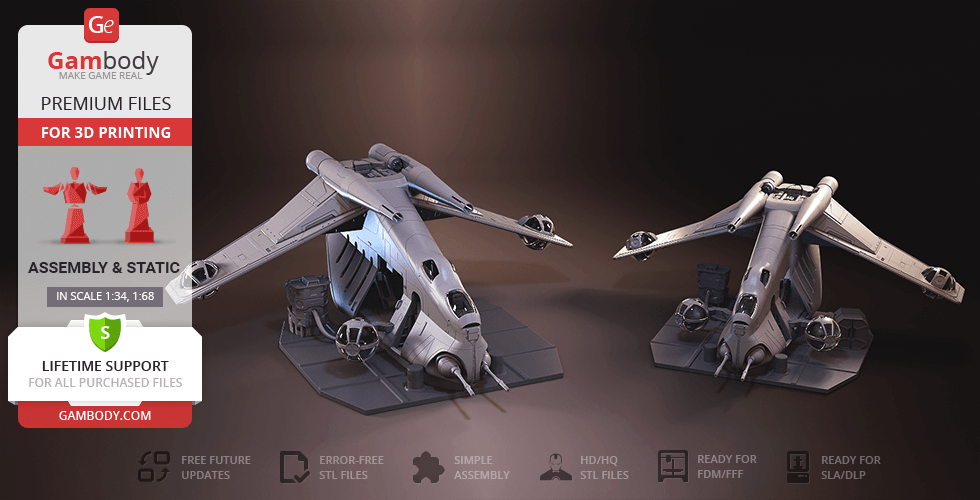
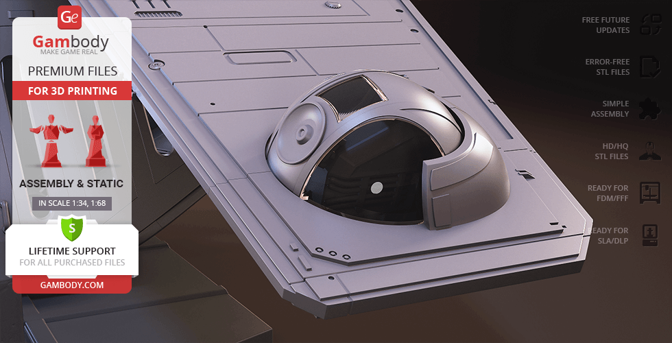
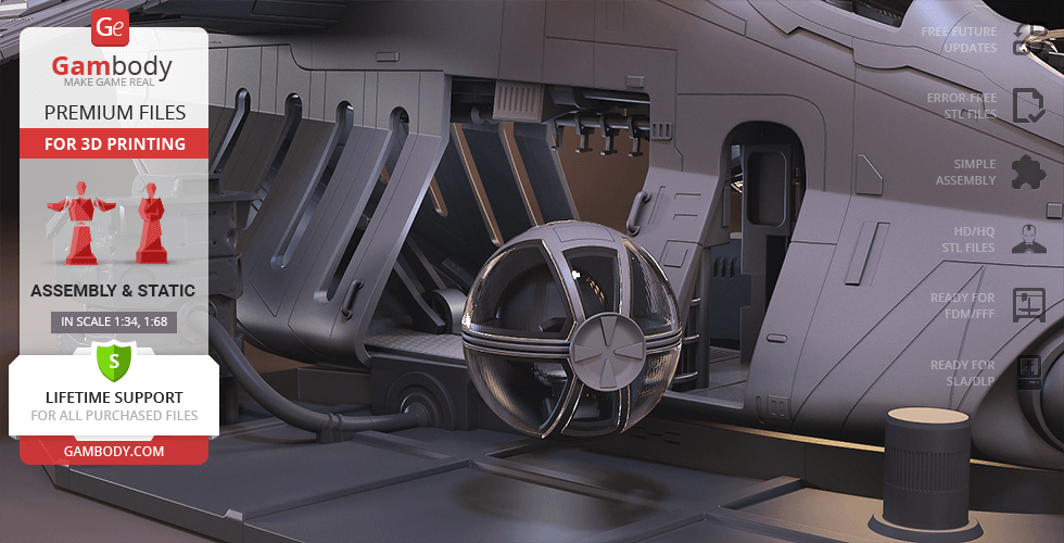
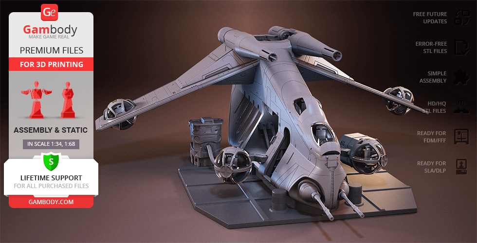
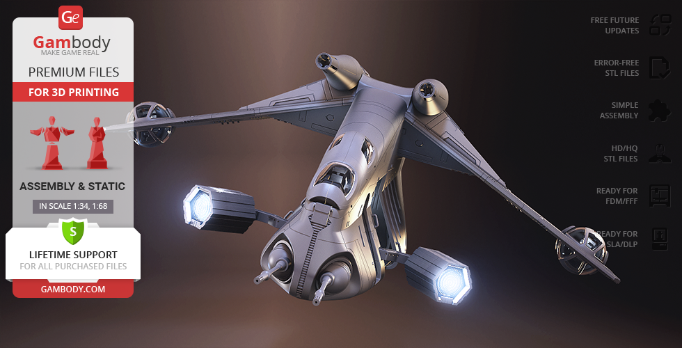
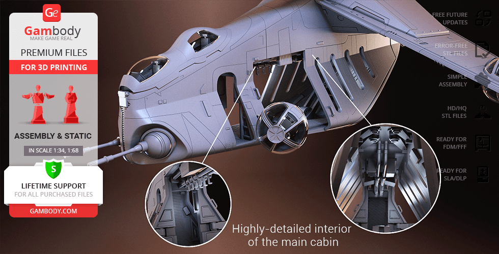
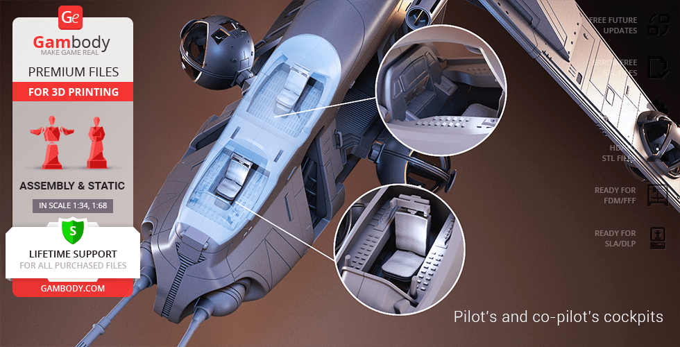
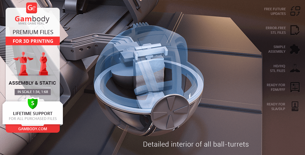
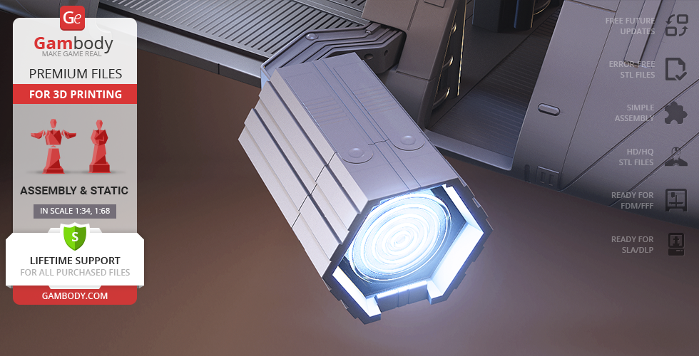
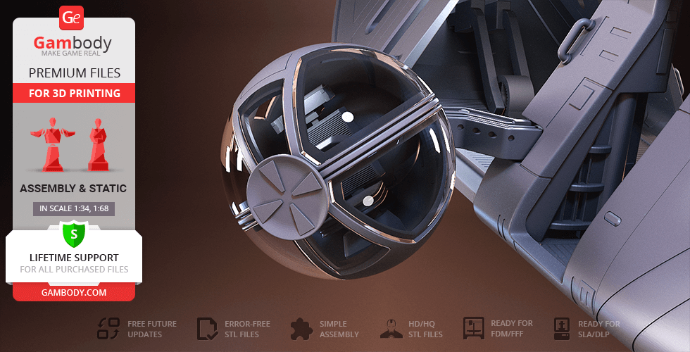
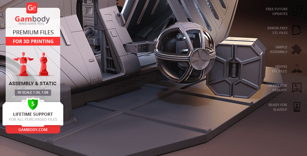
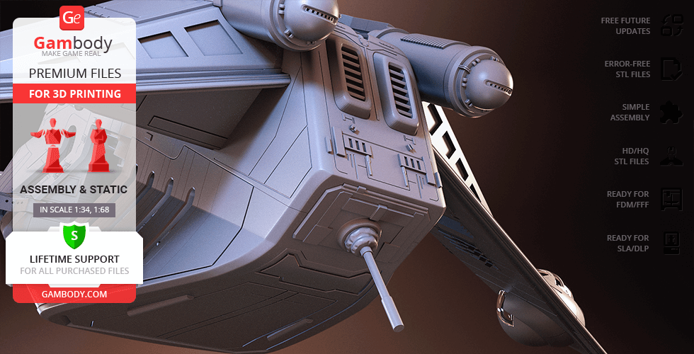
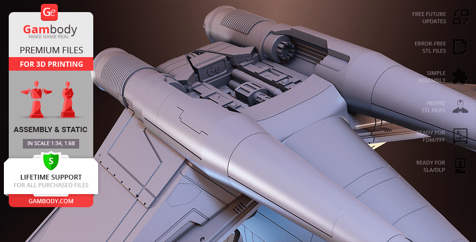
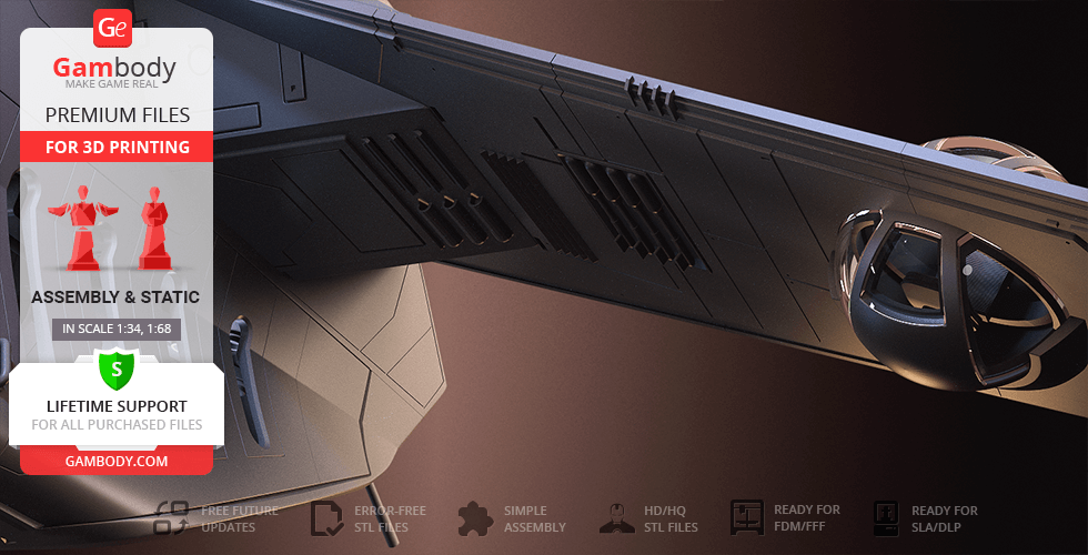
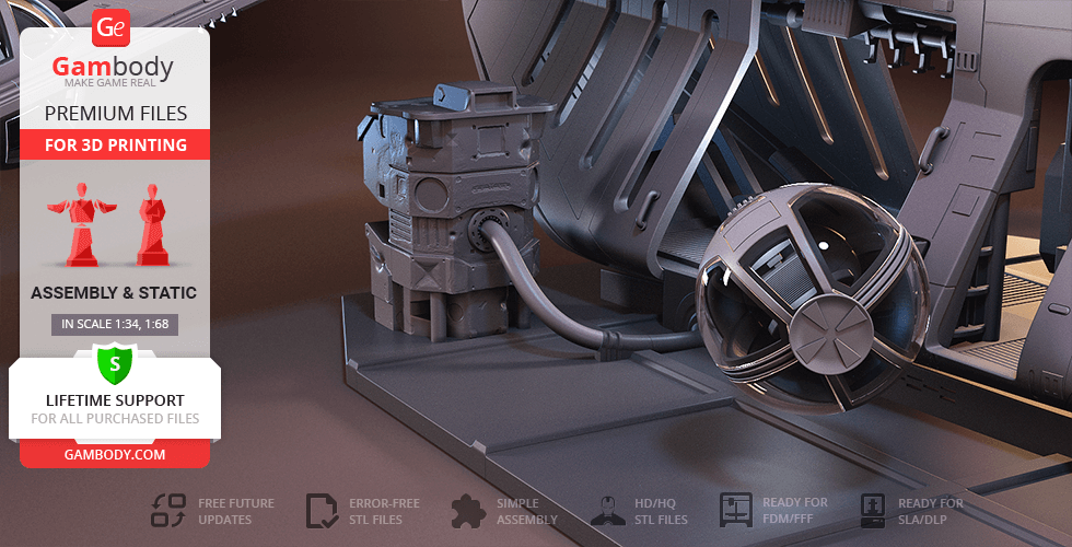
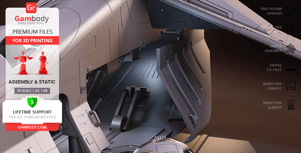
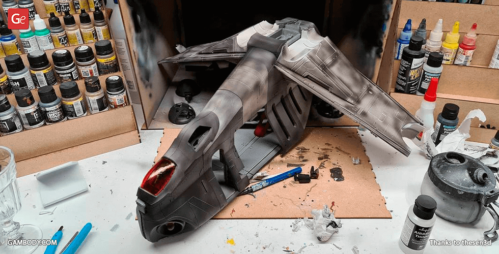
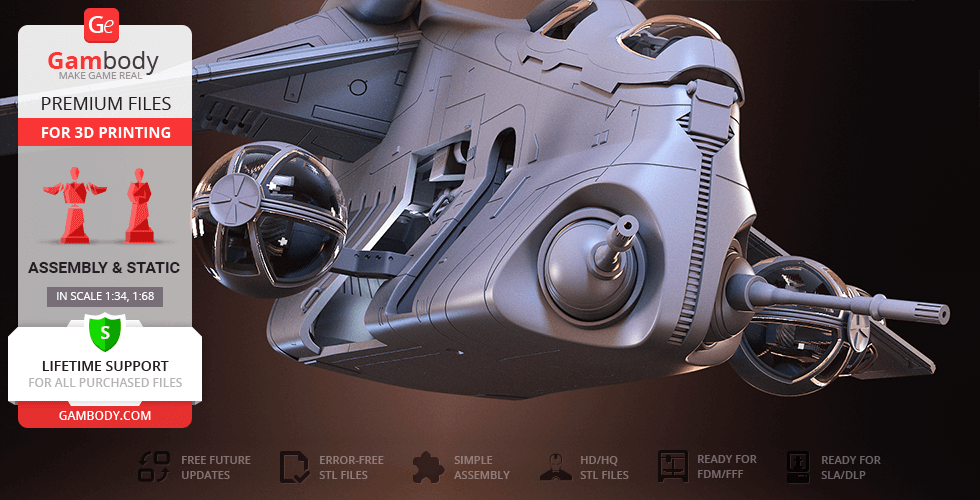
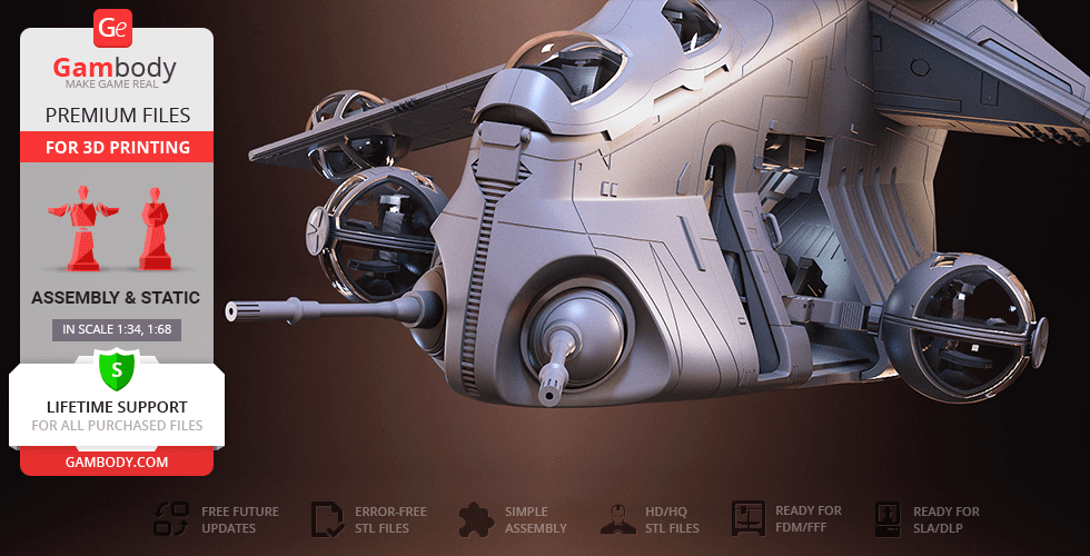
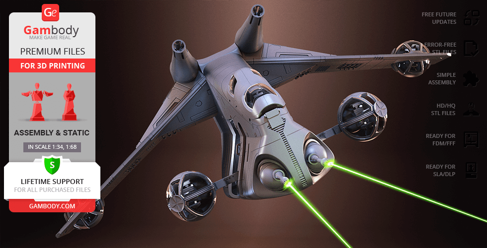
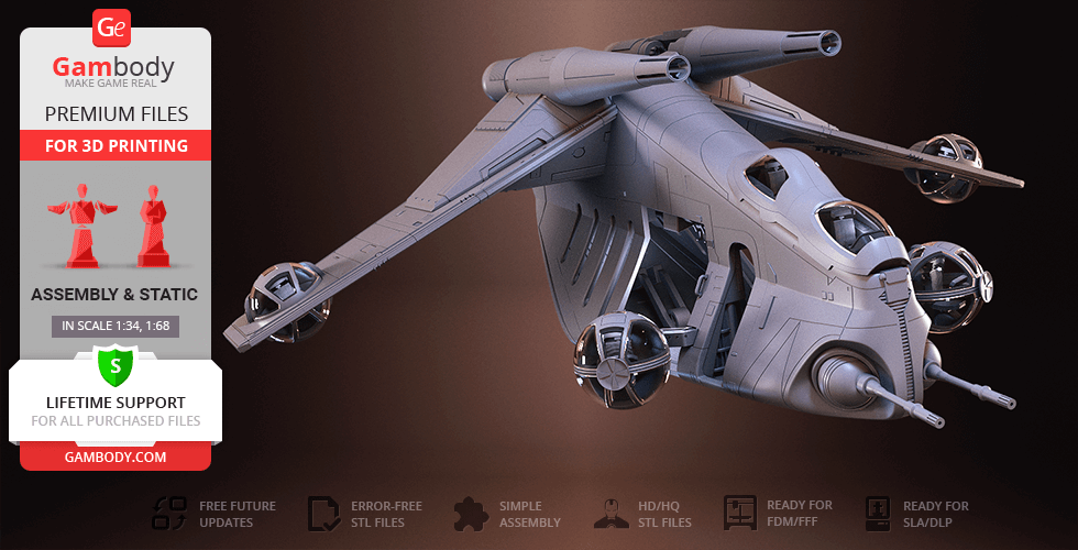
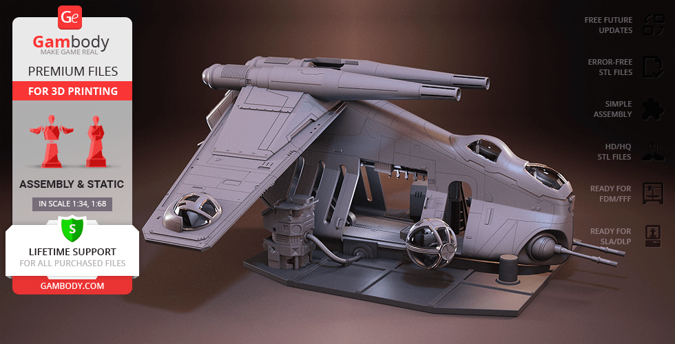
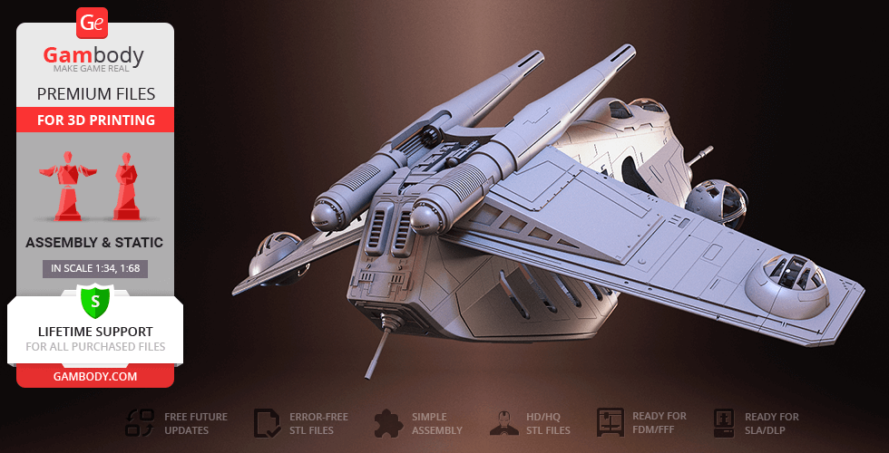
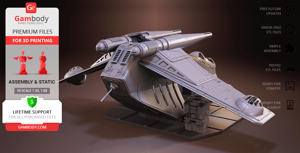
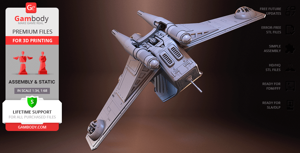
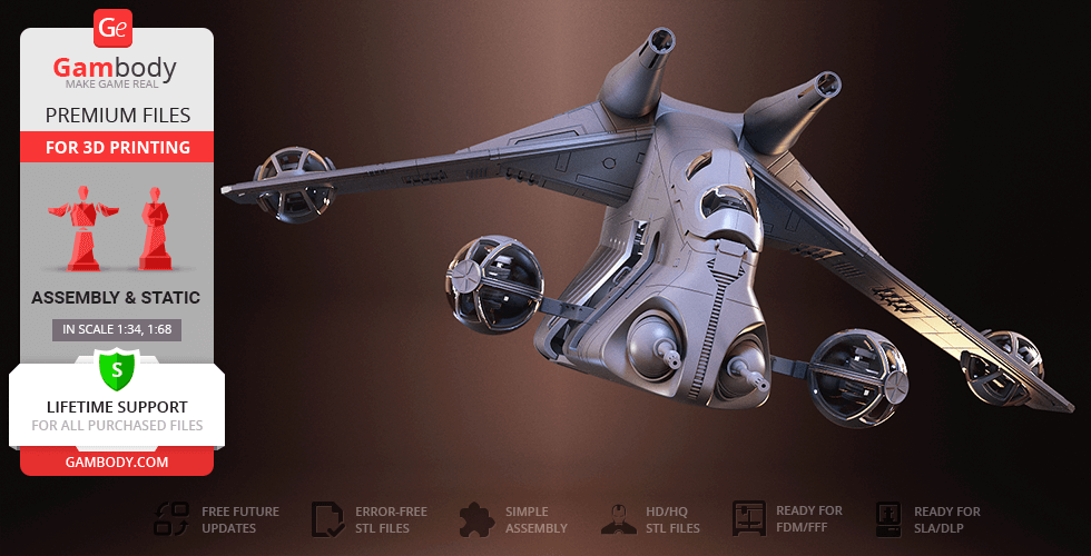
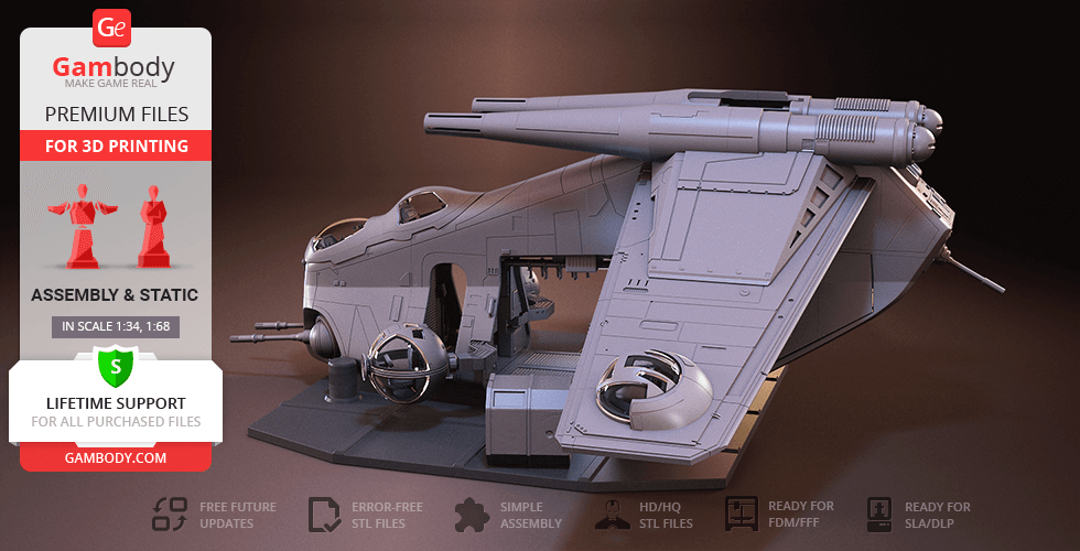
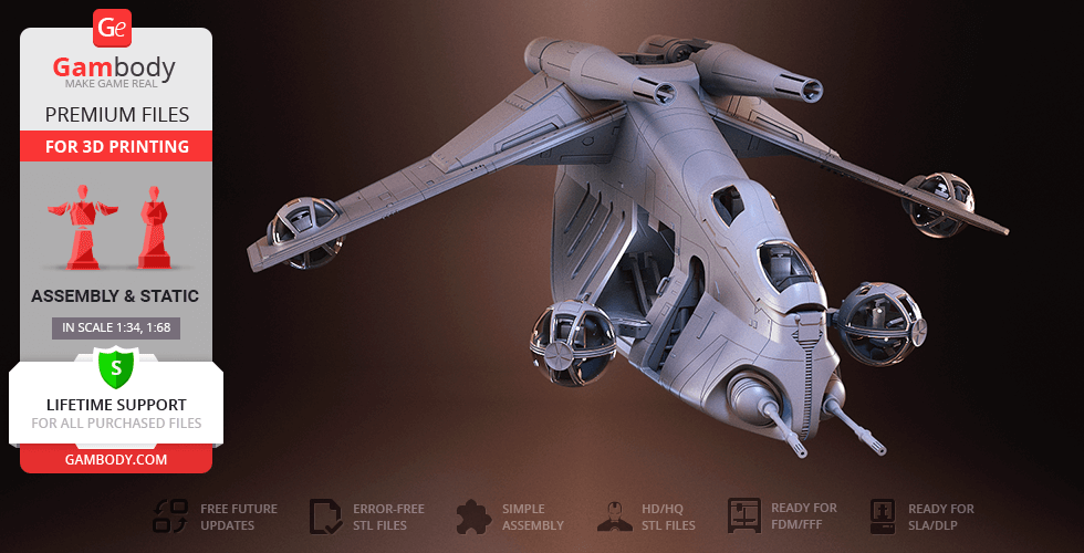
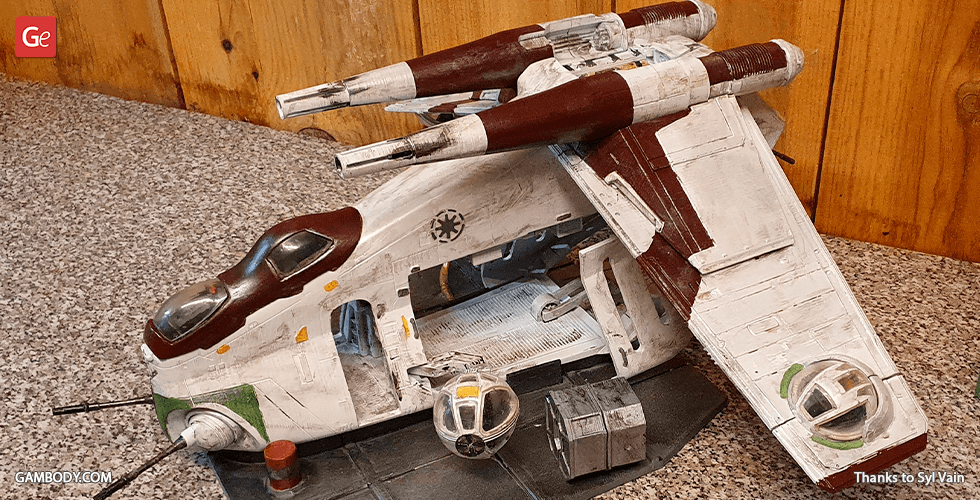
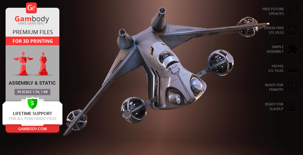
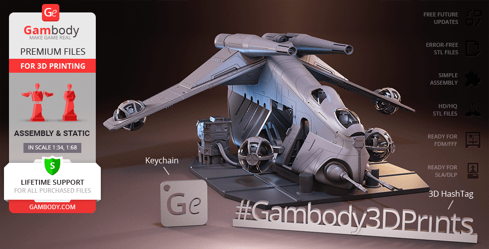
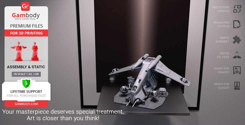
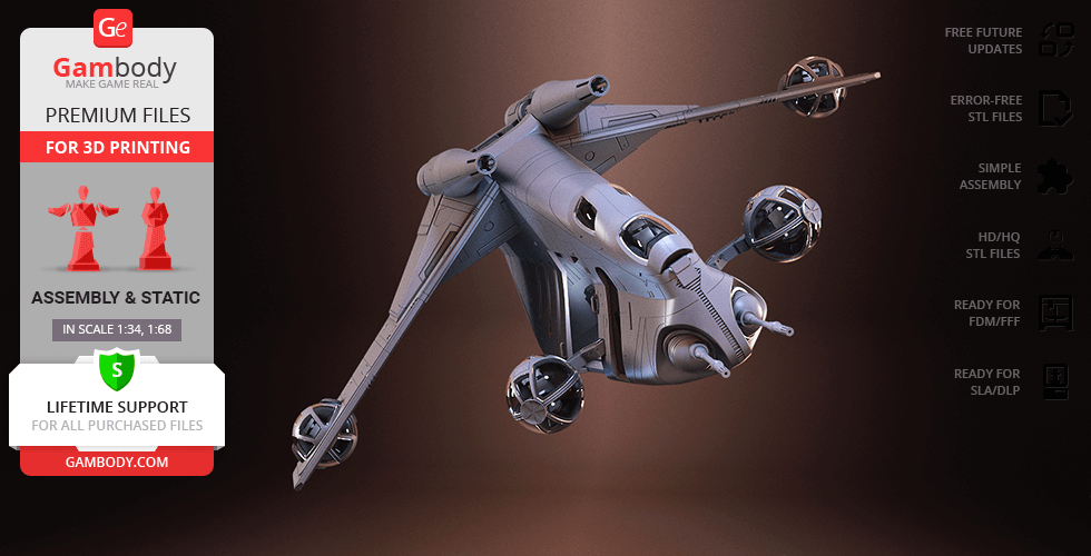
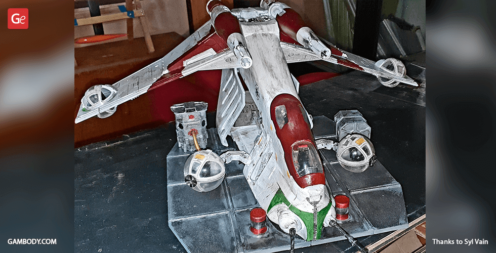
LAAT/i stands for “Low Altitude Assault Transport/infantry” which is a powerful gunship of the Star Wars universe that saw extensive use during the Clone Wars. The flying troop carrier is known for its uncanny likeness to Black Рawk helicopters (minus the propeller blades) and is said to be perfect for infantry transportation and aerial-based support. One of our contributing 3D artists clearly has every intention of bringing to life the gems of Star Wars fleet and we could not be happier! The LAAT/i gunship model for 3D printing is designed with utmost precision that might only compete with the manufacturers from Rothana Heavy Engineering. Taking into account the primary designation of the gunship which is infantry transportation, the author of the model made sure to take care of the authenticity of the LAAT/i's main cabin. Thus, the main hold of the 3D printing gunship is furnished with deckplates, vents, various alcoves, and even is equipped with handles hanging from the ceiling for clone troopers to hold on. The side doors of the Republic attack gunship have tall open viewports and even little handholds to slide them open when landing or during maintenance. Also, the 3D artist paid careful attention to the interior of the double cockpit bubbles of the starship and even installed the seats for the pilot and co-pilot/forward gunner! Offering powerful direct fire support and air-to-ground strikes, the 3D printing LAAT/i is depicted fully armed while carrying chin-mounted adjustable laser cannons and a pair of dorsal missile launchers. The icing on the cake is the 3D printing wing- and armature- mounted ball turrets which are the peculiar feature of the LAAT-series gunship. Finally, having spent circa 190 hours modelling the gunship, the 3D artist decided to place his highly-detailed LAAT/i as if inside the maintenance hangar, surrounded by repair boxes and tool cases. The star of the battle of Geonosis and arguably the most iconic craft to serve in the Clone Wars, the LAAT/i Gunship is ready to join your 3D printing fleet!
ADAPTATION FOR 3D PRINTING
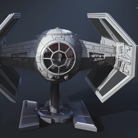
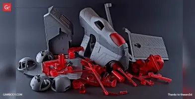
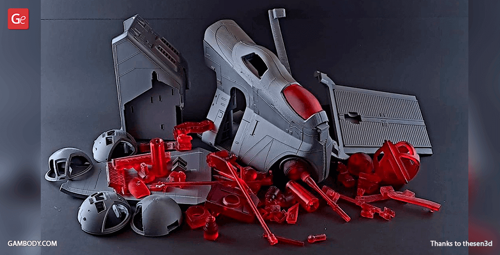
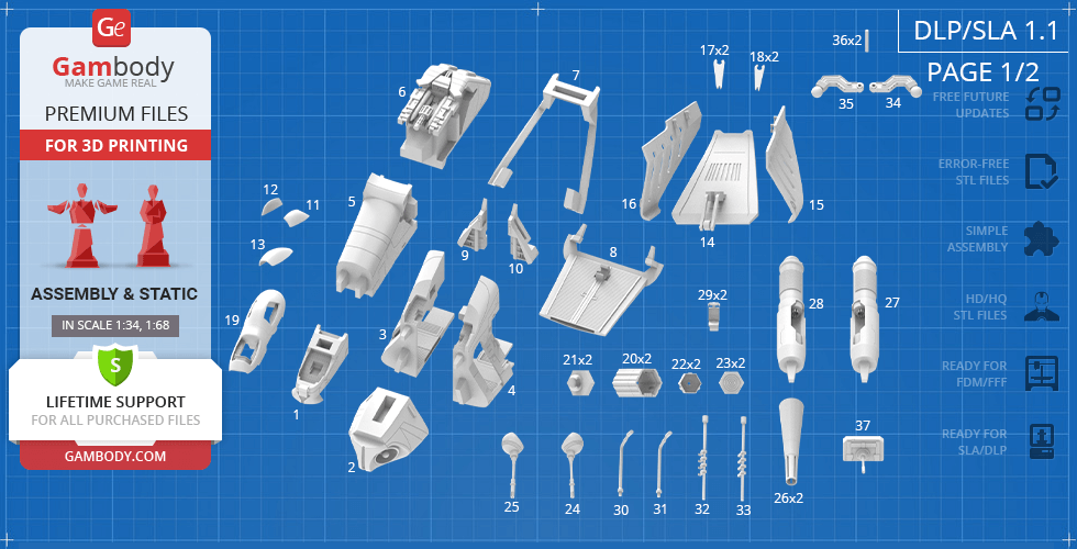
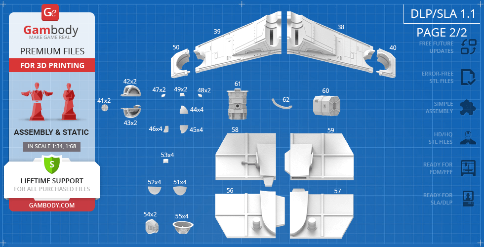
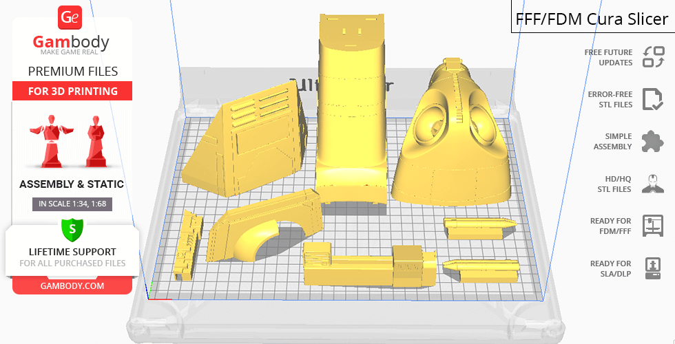
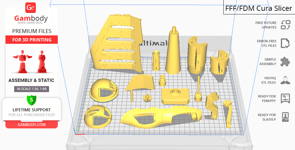
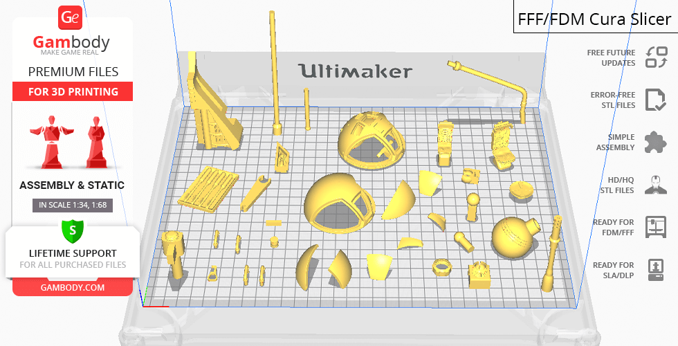
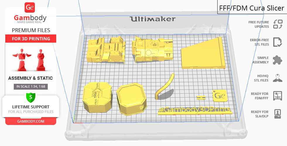
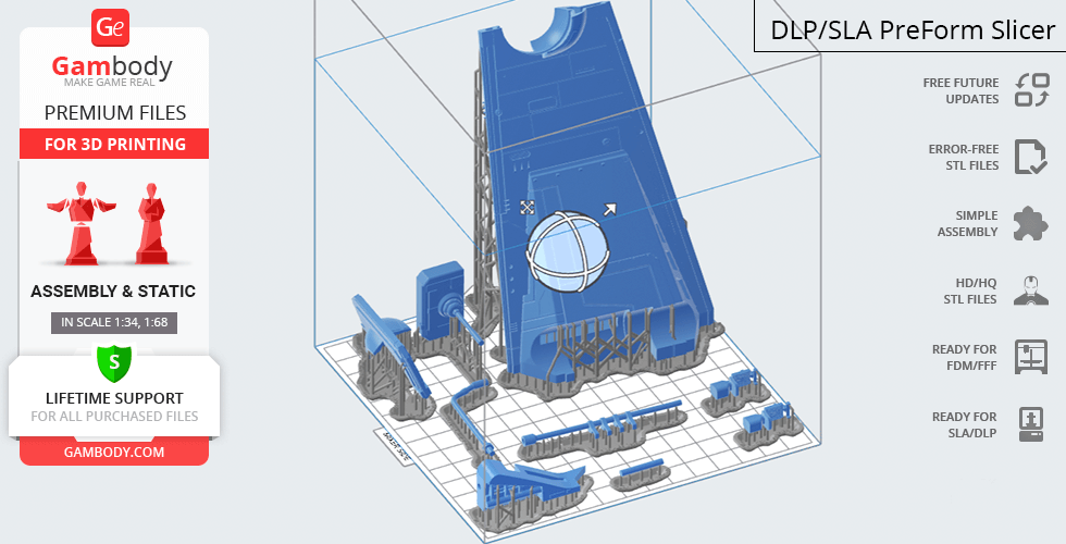
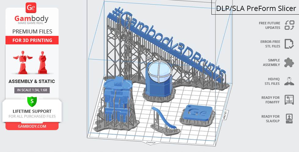
LAAT/i Gunship for 3D printing is a static assembly model and its moderation and adaptation for different types of 3D printers took Gambody team 45 hours in total. For you to receive the cleanest 3D printing result possible and to minimize the amount of filament needed for generated support the gunship model was divided into many assembly parts, e.g. its tail cannon, laser cannons, sliding side doors, ball turrets, pilot and gunner seats, dorsal missile launchers, tail ramp, handrails, etc. are provided as separate STL files. Various special mechanisms were introduced to ensure that the model has fully articulated elements in it (please, see “Versions’ Specifications”). For you to display the LAAT/i Gunship model among your Star Wars collection there is a platform provided that is made to resemble the fragment of a hangar. In order for the platform to fit the build plates of the average 3D printers, it was divided into 16 parts. All assembly parts are provided in STL files in recommended positions that were worked out in order to ensure the smoothness of the details’ surfaces after printing and that the 3D printing beginners won't face difficulties when placing the parts on a build plate. When downloading any model's file you will also receive "AssemblyManual" for FFF/FDM 1.0 and DLP/SLA/SLS 1.0 versions in PDF format. We highly recommend that you get acquainted with the “Assemblyvideo” and "Assembly Manual" before getting down to the LAAT/i Gunship model.
The model is saved in STL files, a format supported by most 3D printers. All STL files for 3D printing have been checked in Netfabb and no errors were shown.
The model's scale was calculated from the actual length of LAAT/i Gunship that is 17600 mm. The 3D printing model's chosen scale is 1/34 for the FFF/FDM version and 1/68 for the DLP/SLA/SLS version.
VERSIONS' SPECIFICATIONS
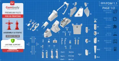
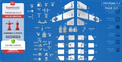
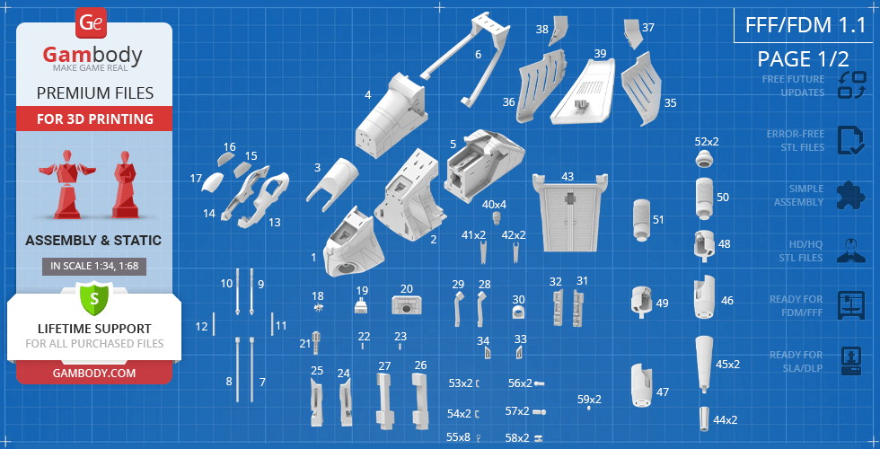
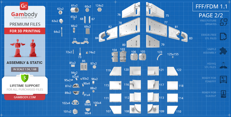
FFF/FDM 1.1 version features:
- Contains 125 parts;
- A printed model is 208 mm tall, 540 mm wide, 514 mm deep;
- Improveddesign with correct proportions and scale;
- Improved scale of the cockpit;
- Improved scale of the armature-mounted ball turrets;
- Reworked wing-mounted ball turrets;
- Added possibility for LED wiring of the engine and the cockpit;
- Assembly kit includes lock 125_Ge_Lock_x155 to connect the model's parts securely without glue that needs to be printed 155 times;
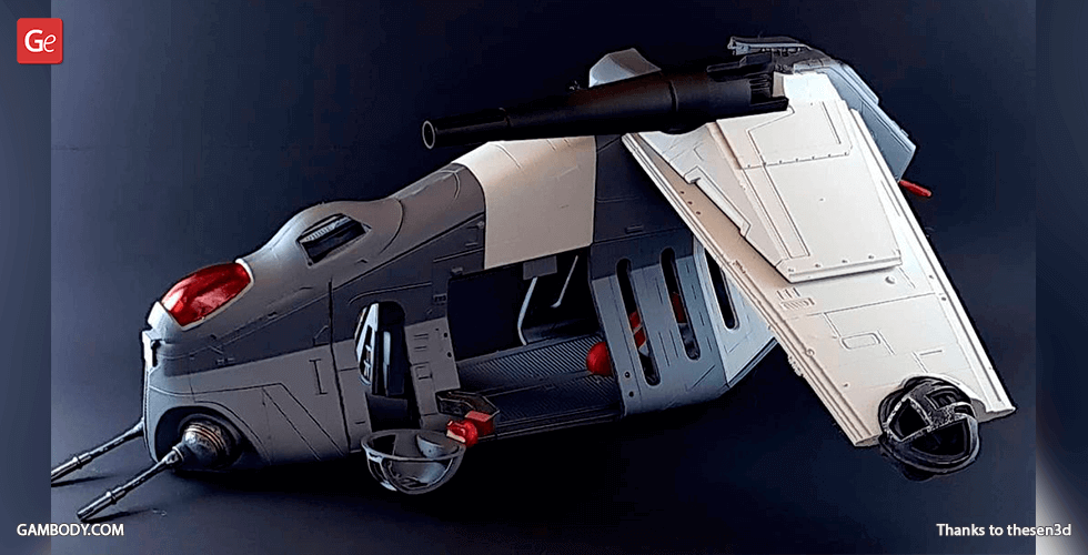
- The modification of the gunship with open side doors for swift and safe deployment of an entire platoon of clone troopers;
- Highly-detailed interior of the main cabin, double cockpit bubbles, and all ball turrets;
- Eight independent handles hanging from the ceiling of the main cabin (but you may print and assemble as many as you like);
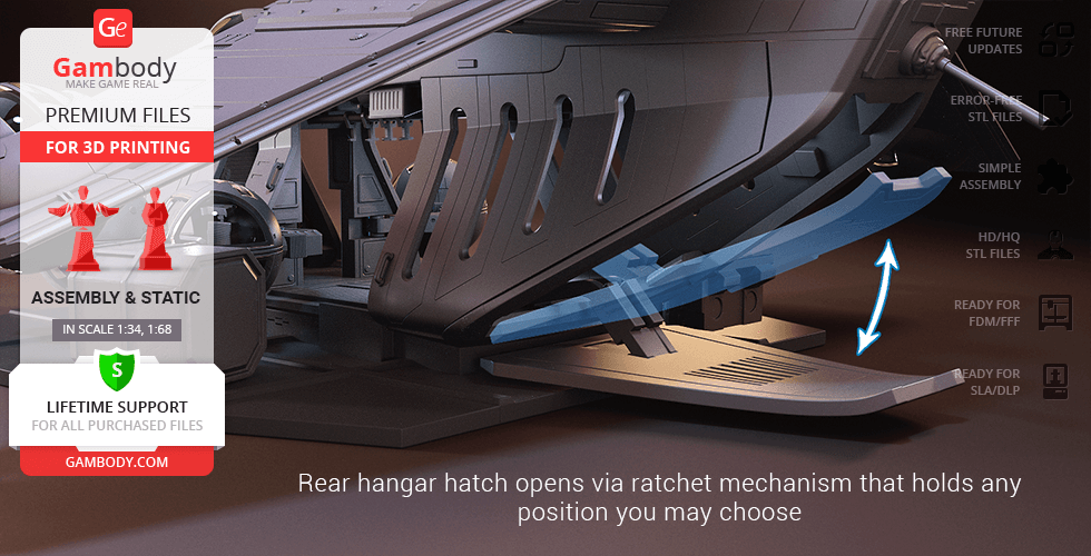
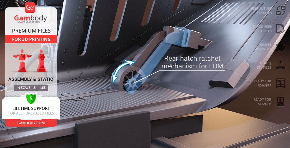
- Rear hangar hatch (tail ramp) opens with the help of a ratchet mechanism system that can hold any position of the door you may choose;
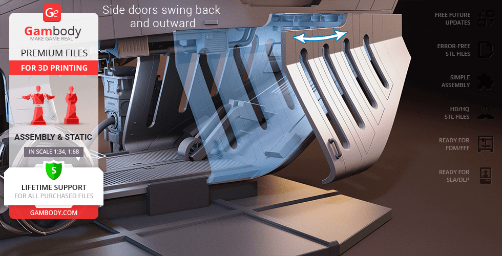
- Side doors swing back and outward;
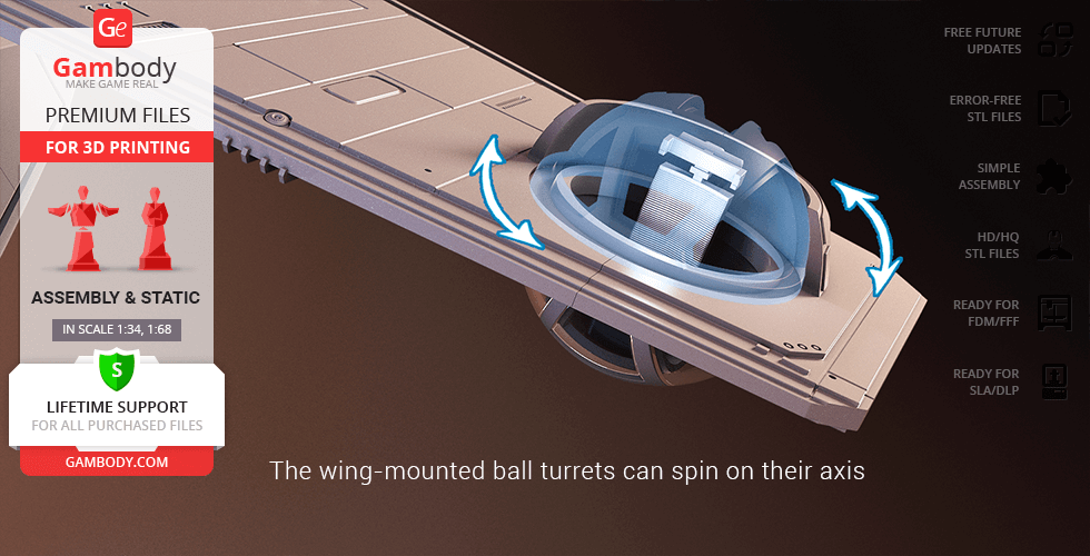
- The wing-mounted ball turrets can spin on their axis;
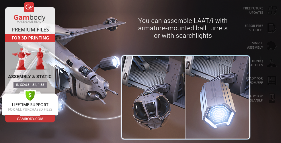
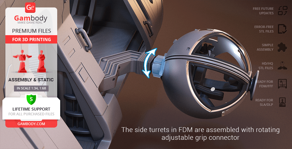
- The armature-mounted ball turrets are assembled with the adjustable grip connector that allows the full rotation of the ball-and-claw joints that you can control by adjusting the tightening nut;
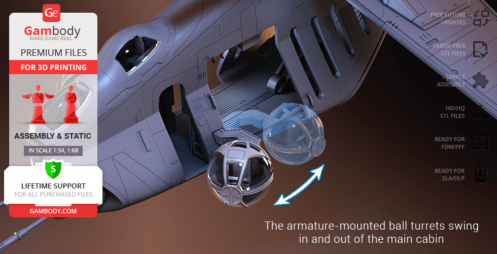
- The armature-mounted ball turrets can swing in and out of the main cabin;
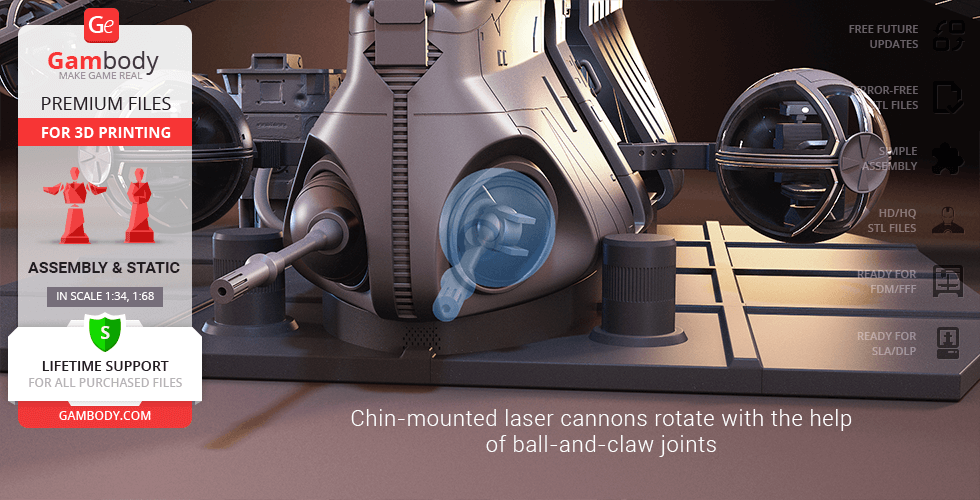
- A pair of chin-mounted laser cannons rotate with the help of ball-and-claw joints;
- Windows of the double cockpit bubbles and ball turret glasses are provided separately to be printed with the transparent material;
- The assembly kit includes various boxes that you can print in any quantity and arrange them on the platform in random order;
- The platform is designed to resemble a fragment of a hangar and has a special stand to position the LAAT/i;
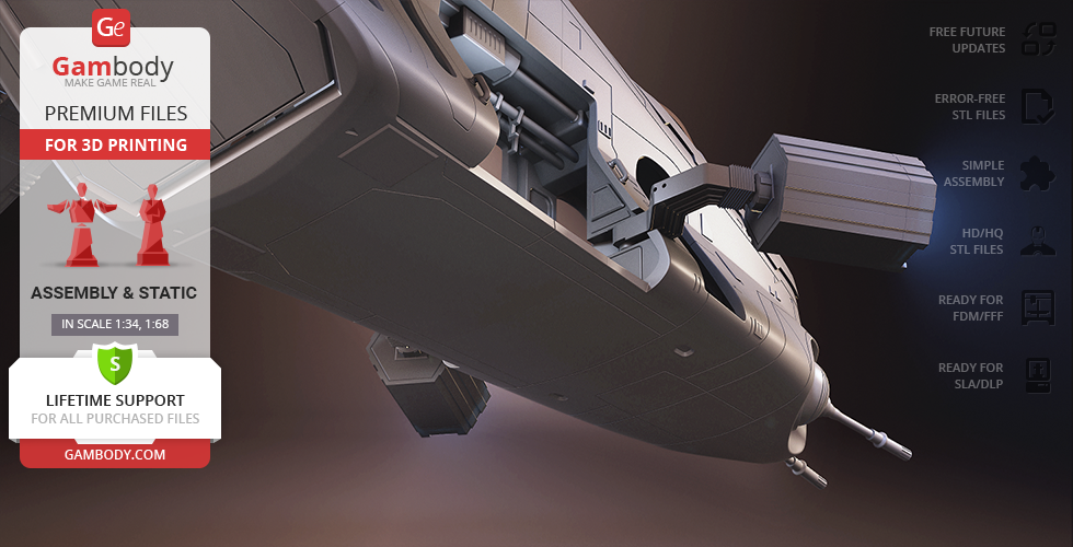
- The dorsal-mounted rocket launchers have several unclad areas to reveal the highly-detailed design of the Gunship;
- All parts are divided in such a way that you will print them with the smallest number of support structures.
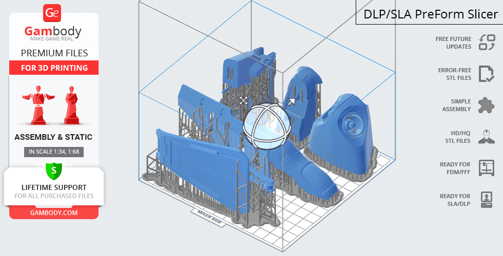
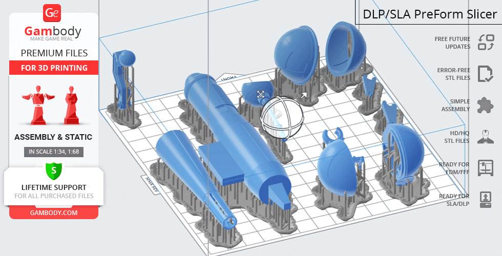
DLP/SLA/SLS 1.1 version features:
- Contains 62 parts;
- A printed model is 104 mm tall, 270 mm wide, 257 mm deep;
- Improveddesign with correct proportions and scale;
- Improved scale of the cockpit;
- Improved scale of the armature-mounted ball turrets;
- Reworked wing-mounted ball turrets;
- The modification of the gunship with open side doors for swift and safe deployment of an entire platoon of clone troopers;
- Highly-detailed interior of the main cabin, double cockpit bubbles, and ball-turrets;
- Rear hangar hatch (tail ramp) opens with the help of a ball-and-claw connector;
- Side doors swing back and outward;
- The wing-mounted ball turrets can spin on their axis;
- The armature-mounted ball turrets rotate with the help of ball-and-claw joints and can swing in and out of the main cabin;
- A pair of chin-mounted laser cannons rotate with the help of ball-and-claw joints;
- The assembly kit includes various boxes that you can print in any quantity and arrange them on the platform in random order;
- The platform is designed to resemble a fragment of a hangar and has a special stand to position the LAAT/i;
- The dorsal-mounted rocket launchers have several unclad areas to reveal the highly-detailed design of the Gunship;
- Windows of the double cockpit bubbles and ball turret glasses are provided separately to be printed with the transparent material;
- All parts are divided in such a way to fit the build plates and to ensure that support structures are generated where needed.
FFF/FDM 1.0 and DLP/SLA/SLS 1.0 versions features:
- The originalversions of the LAAT/i Gunship 3D Printing Model with incorrectproportions;
- FFF/FDM 1.0 version contains 174 parts and is 251 mm tall, 650 mm wide, 620 mm deep;
- DLP/SLA/SLS 1.0 contains 54 parts and is 125 mm tall, 325 mm wide, 310 mm deep;
- The assembly and features are mostly the same as for FFF/FDM 1.1 and DLP/SLA/SLS 1.1.
WHAT WILL YOU GET AFTER PURCHASE?
- STL files of LAAT/i Gunship Model for 3D printing which consist of 228 parts;
- 4 versions of files for this model for FFF/FDM and DLP/SLA/SLS printers;
- High-poly detailed model of LAAT/i Gunship;
- Assembly Manual for FFF/FDM 1.0 and DLP/SLA/SLS 1.0 versions in PDF format;
- Detailed settings that we provide as a recommendation for Cura , Simplify3D and Slic3r for the best print;
- Full technical support from the Gambody Support Team.
You can get the model of LAAT/i Gunship for 3D Printing immediately after the purchase! Just click the green Buy button in the top-right corner of the model’s page. You can pay with PayPal or your credit card.
Watch the tutorial on how to assemble LAAT/i Gunship 3D Printing Model at Gambody YouTube channel.
Also, you may like other Star Wars 3D Printing Models, as well as other Space Ships 3D Printing Models.
_______
FAQ:
Where can I print a model if I have no printer?
How to get started with 3D printing?
How to set up my 3D printer?
How to choose right 3D model print bed positioning?
How to paint printed figurine?
Average customer rating (22 reviews)
4.3
Ratings breakdown
Click a star rating to filter reviews
Overall experience
Level of detail in the model
4.2
Model cut quality and assembly guide
4.2
Clarity and accuracy of the model page
4.3
Level of detail in the model
3.7
Model cut quality and assembly guide
3.9
Clarity and accuracy of the model page
4.7
We have addressed this with our Moderation Team, and the engineers have already provided updated files for the FFF/FDM adapted version (1.1 – Correct proportions). Please re-download files #81 and #82 from the Source Files tab on the model page. They will be labeled as UPDATED.
Please do not hesitate to let us know if there is anything else we can assist you with during your LAAT/i Gunship 3D printing project!
Level of detail in the model
5
Model cut quality and assembly guide
5
Clarity and accuracy of the model page
5
Level of detail in the model
3
Model cut quality and assembly guide
3
Clarity and accuracy of the model page
3
Level of detail in the model
4
Model cut quality and assembly guide
4
Clarity and accuracy of the model page
4
Level of detail in the model
5
Model cut quality and assembly guide
5
Clarity and accuracy of the model page
5
Level of detail in the model
5
Model cut quality and assembly guide
5
Clarity and accuracy of the model page
5
Level of detail in the model
5
Model cut quality and assembly guide
5
Clarity and accuracy of the model page
5
Level of detail in the model
5
Model cut quality and assembly guide
5
Clarity and accuracy of the model page
5
Level of detail in the model
5
Model cut quality and assembly guide
5
Clarity and accuracy of the model page
5
Level of detail in the model
3
Model cut quality and assembly guide
3
Clarity and accuracy of the model page
3
Level of detail in the model
5
Model cut quality and assembly guide
5
Clarity and accuracy of the model page
5
Level of detail in the model
4
Model cut quality and assembly guide
4
Clarity and accuracy of the model page
4
Level of detail in the model
1
Model cut quality and assembly guide
1
Clarity and accuracy of the model page
1
Level of detail in the model
4
Model cut quality and assembly guide
4
Clarity and accuracy of the model page
4
Level of detail in the model
5
Model cut quality and assembly guide
5
Clarity and accuracy of the model page
5
Level of detail in the model
5
Model cut quality and assembly guide
5
Clarity and accuracy of the model page
5
Level of detail in the model
5
Model cut quality and assembly guide
5
Clarity and accuracy of the model page
5
Level of detail in the model
3
Model cut quality and assembly guide
3
Clarity and accuracy of the model page
3
Level of detail in the model
4
Model cut quality and assembly guide
4
Clarity and accuracy of the model page
4
Level of detail in the model
3
Model cut quality and assembly guide
3
Clarity and accuracy of the model page
3
Below you'll find detailed slicing settings for Bambu Studio 2.0+, Orca Slicer 2.0+, UltiMaker Cura 5.0+, PrusaSlicer 2.0+, Slic3r 1.3+, Simplify3D 5.0+ to help you get the best results when printing this model. These settings are optimized specifically for this 3D model, but please note they may need slight adjustments depending on your printer or filament. When in doubt, refer to your printer's user manual.
To avoid printing issues and achieve the best quality, we highly recommend applying the following settings:
For better quality use 0.12 mm layer height, for fast printing use 0.2 mm layer height. For pins and the Ge connectors, use 0.2 layer height.
120-150% of your Layer Height
But you can paint the seam if you want.
You have to calibrate this parameter
You have to calibrate this parameter
You have to calibrate this parameter
For pins and power elements of the structure, such as the vehicle frame, use 3 loop
Disabled for vehicles and enabled for characters
For 0,2 Layer Height
The parameters in this tab vary greatly, it all depends on the quality of your printer. For example, if you have a classic Ender3, stick to the minimum parameters, but if you have a newer printer, for example Anycubic cobra 3 v2, you can select the maximum recommended values
Settings for advanced users, change these parameters only if you have sufficient 3D printing expertise
Enable this parameter if your model requires supports
We also recommend placing and removing supports manually in some places using special button
1-2 loops for more thick support
Top Z distance = 1-1.3 layer Height. If the supports are hard to remove, try increasing this setting by 0.1-0,4 mm
Bottom Z distance = 1-1.3 layer Height. If the supports are hard to remove, try increasing this setting by 0.1-0,4 mm
You have to calibrate this parameter which one is better for your filament
Increase this parameter if the supports are hard to remove from walls
For PLA and PETG filament types
5-8 mm is optional for small prints that have bad adhesion to the build plate
You have to calibrate this parameter
Read the description on your filament roll
Read the description on your filament roll and increase this parameter for fast printers
Read the description on your filament roll and increase this parameter for fast printers
For better quality use 0.12 mm layer height, for fast printing use 0.2 mm layer height. For pins and the Ge connectors, use 0.2 layer height.
120-150% of your Layer Height
But you can paint the seam if you want.
0.01-0.05 You have to calibrate this parameter
0.01-0.05 You have to calibrate this parameter
0.1-0.2 You have to calibrate this parameter
For pins and power elements of the structure, such as the vehicle frame, use 3 loop
Disabled for vehicles and ships, enabled for characters
For 0,2 Layer Height
For 0,2 Layer Height
The parameters in this tab vary greatly, it all depends on the quality of your printer. For example, if you have a classic Ender3, stick to the minimum parameters, but if you have a newer printer, for example, Anycubic Kobra 3 Or Bambulab A1, you can select the maximum recommended values.
Settings for advanced users, change these parameters only if you have sufficient 3D printing expertise
Enable this parameter if your model requires supports
We also recommend placing and removing supports manually in some places using special button
Top Z distance = 1-1.3 layer Height. If the supports are hard to remove, try increasing this setting by 0.1-0,4 mm
Bottom Z distance = 1-1.3 layer Height. If the supports are hard to remove, try increasing this setting by 0.1-0,4 mm
Increase this parameter if the supports are hard to remove from walls
For PLA and PETG filament types
5-8 mm is optional for small prints that have bad adhesion to the build plate
Read the description on your filament roll
Read the description on your filament roll and increase this parameter for fast printers
You have to calibrate this parameter
Read the description on your filament roll and increase this parameter for fast printers
Read the description on your filament roll
This field is filled in according to your printer specifications when you add it to the slicer.
You can add custom G-code here for the start and end of the print. However, be careful - this is for advanced users only!
You have to calibrate your printer using Ge retraction test models
Retraction Length: For direct-drive setups use 0.5 mm to 2.5 mm; for Bowden extruders use 5 to 7 mm
This is how fast the filament is pulled back—40-60 mm/s for direct drive and 30-50 mm/s for Bowden setups.
You have to calibrate this parameter: Reduce it until the printer starts to hit the parts with the nozzle during printing, then increase it by 0.2.
For better quality use 0.12 mm layer height, for fast printing use 0.2 mm layer height. For pins and the Ge connectors, use 0.2 layer height.
120-150% of your Layer Height
To increase the strength of the print parts, use wall line count: 3
For pins and connectors use 50% Infill
These parameters are for standard PLA plastic. If you are using a different type of plastic, check the printing temperature recommended by the manufacturer. Also, read the description on your filament spool. For fast printers, add +30 °C to the current parameters.
The parameters in this tab vary greatly, it all depends on the quality of your printer. For example, if you have a classic Ender3, stick to the minimum parameters, but if you have a newer printer, for example Anycubic cobra 3 v3, you can select the maximum recommended values
Settings for advanced users, change these parameters only if you have sufficient 3D printing expertise.
You need to calibrate this parameter using Gambody test models. These values are average values for a Direct Drive extruder; for a Bowden extruder, the values should be increased.
You need to calibrate this parameter using Gambody test models. These values are average values for a Direct Drive extruder; for a Bowden extruder, the values should be increased.
Use this value other than 0 if your nozzle catches on the internal infill during travel moves. Try to keep this value as low as possible in height.
Use normal supports to support large, straight surfaces (most mechanical or technical parts).
You have to calibrate this parameter according to the capabilities of your printer and your filament, using a Gambody test models.
Use 1 instead of 0 if your supports are thin and tall. They will be harder to remove, but much stronger.
Top Z distance = 1-1.3 layer Height. If the supports are hard to remove, try increasing this setting by 0.1-0,4 mm
Increase this parameter if the supports are hard to remove from walls
Use tree supports to support complex objects, such as characters.
You have to calibrate this parameter according to the capabilities of your printer and your filament, using a Gambody test models.
Top Z distance = 1-1.3 layer Height. If the supports are hard to remove, try increasing this setting by 0.1-0,4 mm
Increase this parameter if the supports are hard to remove from walls
Use a skirt for all parts when printing on outdated printers.
Use a brim when printing thin but tall parts, as well as parts with a small bed adhesion area.
For better quality use 0.12 mm layer height, for fast printing use 0.2 mm layer height. For pins and the Ge connectors, use 0.2 layer height.
120-150% of your Layer Height
for 0.2 Layer Height
But you can paint the seam if you want.
(for PLA and PETG)
(5-8 mm is optional for small prints that have bad adhesion to the build plate)
Enable this parameter if your model requires supports
(45-50 degree)You have to calibrate this parameter according to the capabilities of your printer
and your filament, using a Gambody test models.
Top contact Z distance = 1-1.3 layer Height. If the supports are hard to remove, try
increasing this setting by 0.1-0,4 mm
Top contact Z distance = 1-1.3 layer Height. If the supports are hard to remove, try
increasing this setting by 0.1-0,4 mm
Increase this parameter if the supports are hard to remove from walls
The parameters in this tab vary greatly, it all depends on the quality of your printer. For example, if you have a classic Ender3, stick to the minimum parameters, but if you have a newer printer, for example Anycubic cobra 3 v3, you can select the maximum recommended values
Settings for advanced users, change these parameters only if you have sufficient 3D printing expertise. Use the minimum value for outdated printers without acceleration calibration, and the maximum value for modern printers if you need it.
These settings only work for 3D printers with multiple extruders
You can try setting all parameters in this section, except the First layer, to values between 0.75% of your nozzle diameter and 1.25% of your nozzle diameter. Adjusting them will help you work out the optimal parameters for the best quality for your print. As for the First layer, you can set it to 150% of the diameter of your nozzle for better adhesion to the build plate (for a nozzle with a diameter of 0.4 mm, the First layer extrusion width can be from 0.3 mm to 0.5 mm)
For better printing quality you have to calibrate this parameter using Gambody test model.
Check your filament manufacturer's temperature recommendations on the spool.
Cooling parameters depends on the material you use for printing.
*for PLA
For better quality use 0.12 mm layer height, for fast printing use 0.2 mm layer height. For pins and the Ge connectors, use 0.2 layer height.
120-150% of your Layer Height
For 0.12 Layer Height
For 0.12 Layer Height
For pins and connectors use 50% Infill
Use skirt for outdated 3d printers
(5-8 mm is optional for small prints that have bad adhesion to the build plate)
Enable this parameter if your model requires supports
(45-60 degree)You have to calibrate this parameter according to the capabilities of your printer and your filament, using a Gambody test models
Contact Z distance = 1-1.3 layer Height. If the supports are hard to remove, try increasing this setting by 0.1-0,4 mm
The parameters in this tab vary greatly, it all depends on the quality of your printer. For example, if you have a classic Ender3, stick to the minimum parameters, but if you have a newer printer, for example Anycubic cobra 3 v3, you can select the maximum recommended values
Settings for advanced users, change these parameters only if you have sufficient 3D printing expertise. Use the minimum value for outdated printers without acceleration calibration, and the maximum value for modern printers if you need it.
You have to calibrate this parameter from 0.9 to 1.1 according to the capabilities of your printer and your filament, using a Gambody test models.
Check your filament manufacturer's temperature recommendations on the spool.
Cooling parameters depends on the material you use for printing.
Calibrate this value if you need to reduce or improve the adhesion between the plastic and the heat bed
Your current nozzle diameter
You need to calibrate this parameter using Gambody test models. These values are average values for a Direct Drive extruder; for a Bowden extruder, the values should be increased.
Your current nozzle diameter
You have to calibrate this parameter using Gambody test models.
You need to calibrate this parameter using Gambody test models. These values are average values for a Direct Drive extruder; for a Bowden extruder, the values should be increased.
For better quality use 0.12 mm layer height, for fast printing use 0.2 mm layer height. For pins and the Ge connectors, use 0.2 layer height.
For 0,2 Layer Height
For 0,2 Layer Height
To increase the strength of the print parts, use Outline Perimeters: 3
You can enable this parameter to print rounded or spherical models, as well as character models.
Use this option only if your parts are too tight. but better calibrate your printer extrusion
Use this option only if your parts are too tight. but better calibrate your printer extrusion
Use 2 and more if you want to create skirt instead brim
1-2 for skirt and 10-20 for brim
Use for wipe nozzle if you need
Use For ABS filament
For pins and connectors use 50% Infill
Top Z distance = 1-1.3 layer Height. If the supports are hard to remove, try increasing this setting by 0.1-0,4 mm
Calibrate your filament and detect optimal temperature for it
Average temperature for PLA filament
The parameters in this tab vary greatly, it all depends on the quality of your printer. For example, if you have a classic Ender3, stick to the minimum parameters, but if you have a newer printer, for example Anycubic cobra 3 v3, you can select the maximum recommended values
Settings for advanced users, change these parameters only if you have sufficient 3D printing expertise.