


Files
3D model format
Stereolithography (.stl)
Total files
Slicer settings
Mesh error check
Netfabb
Support
Lifetime support from Gambody team
Update requests
Available to verified buyers
Model complexity
Advanced: may require tuning print settings or support placement, plus precise fitting, gluing, or sanding.
Expert: demanding print setup with intricate parts. Requires post-processing skills, attention to detail, and patience.
Model versions
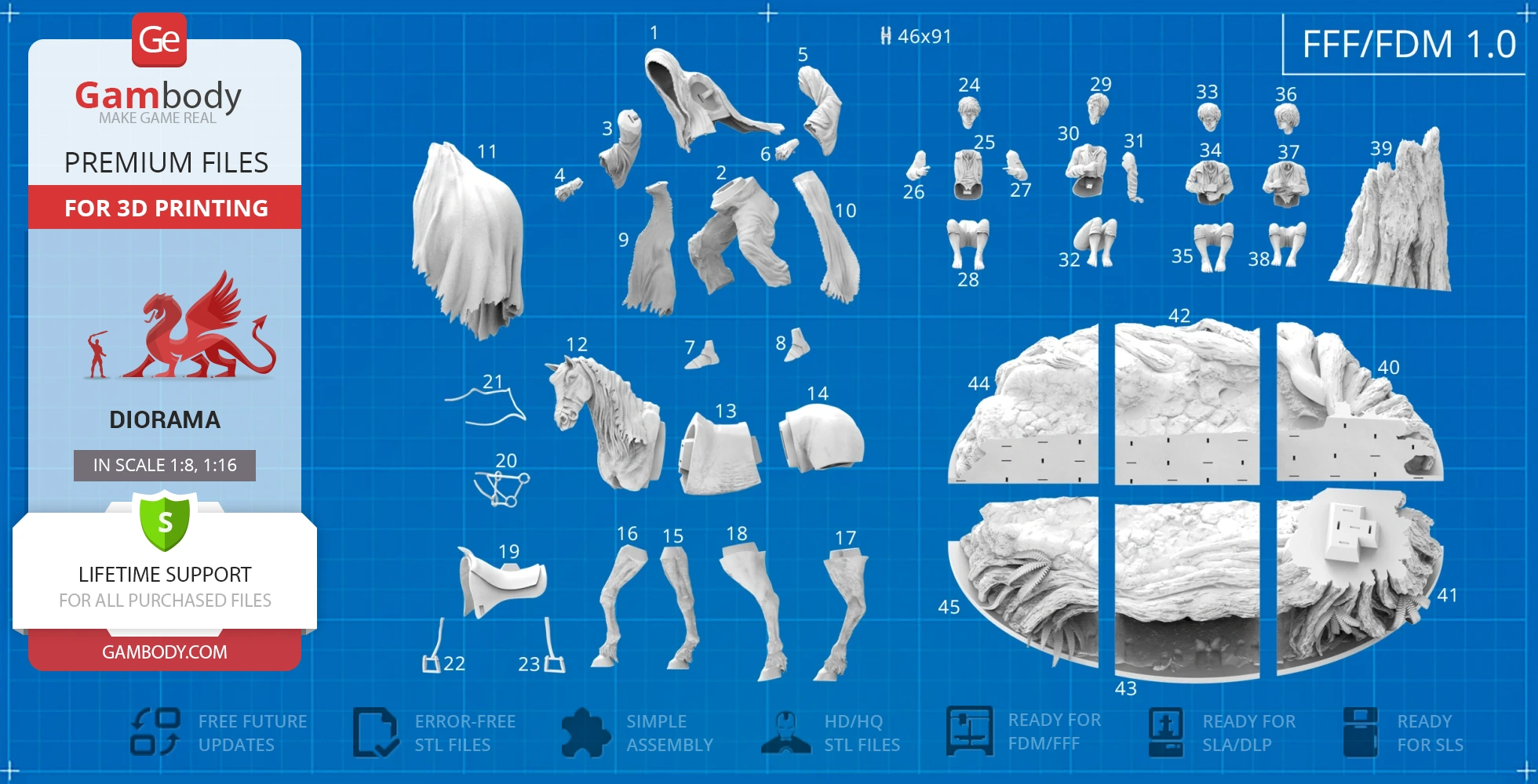
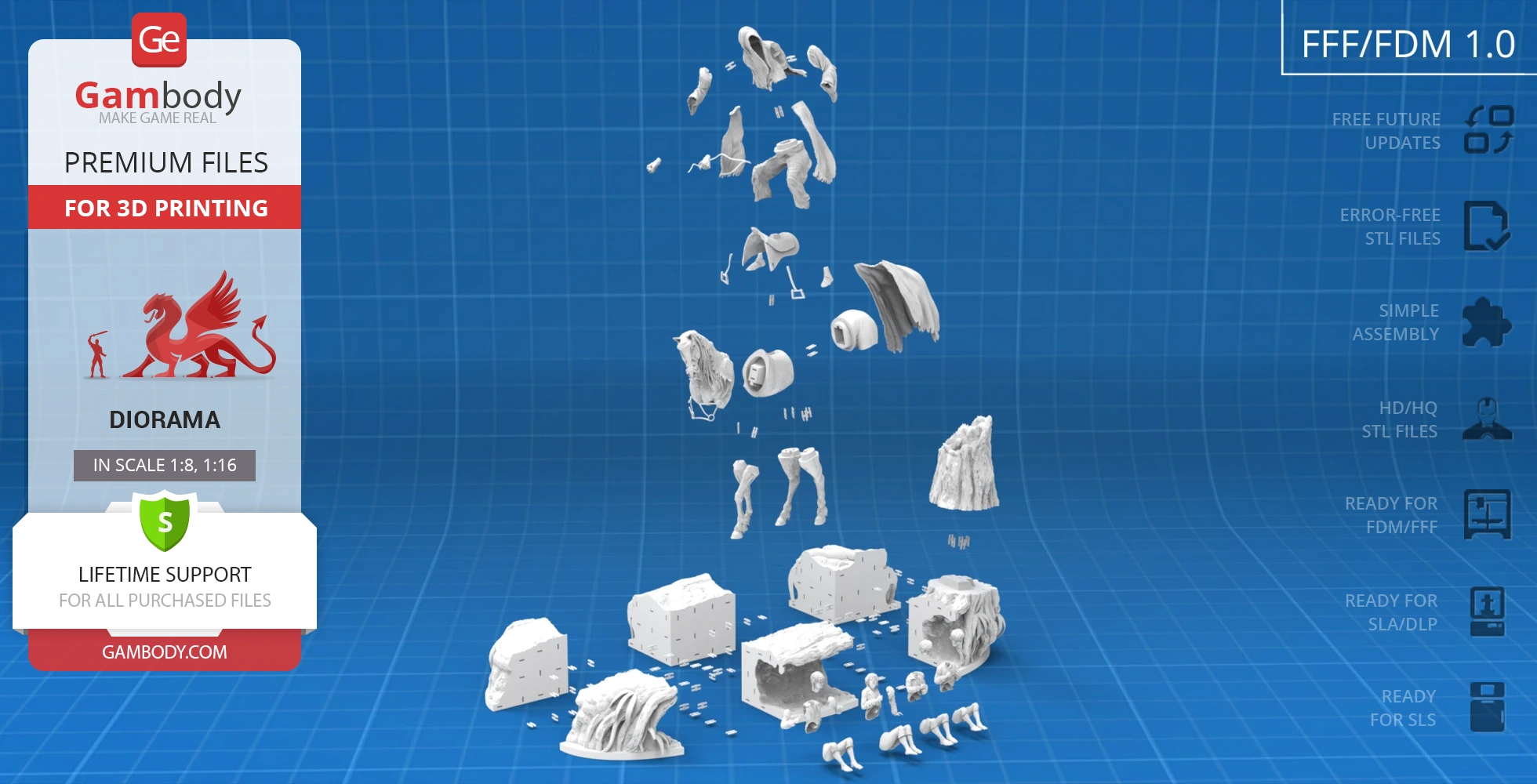
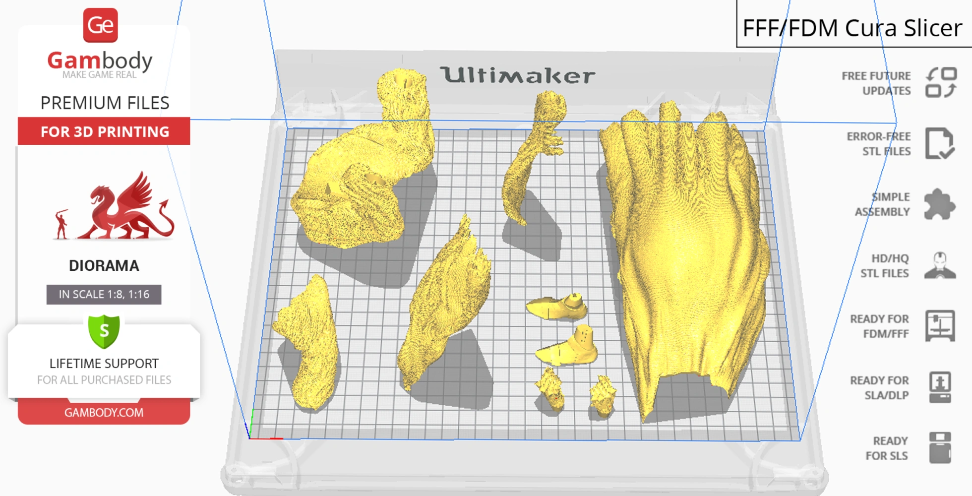
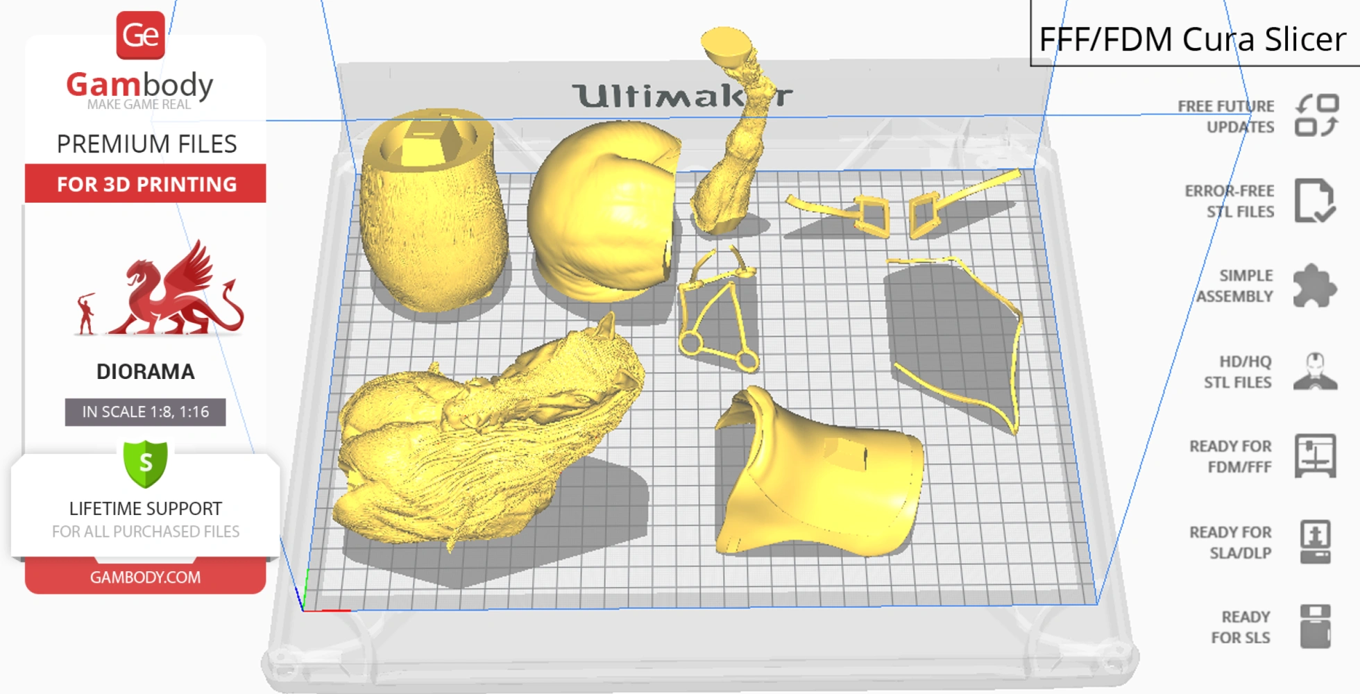
FFF/FDM
Assembly method
Connectors
Features
The assembly parts are connected using specially designed integrated connectors that fit securely into the corresponding slots;
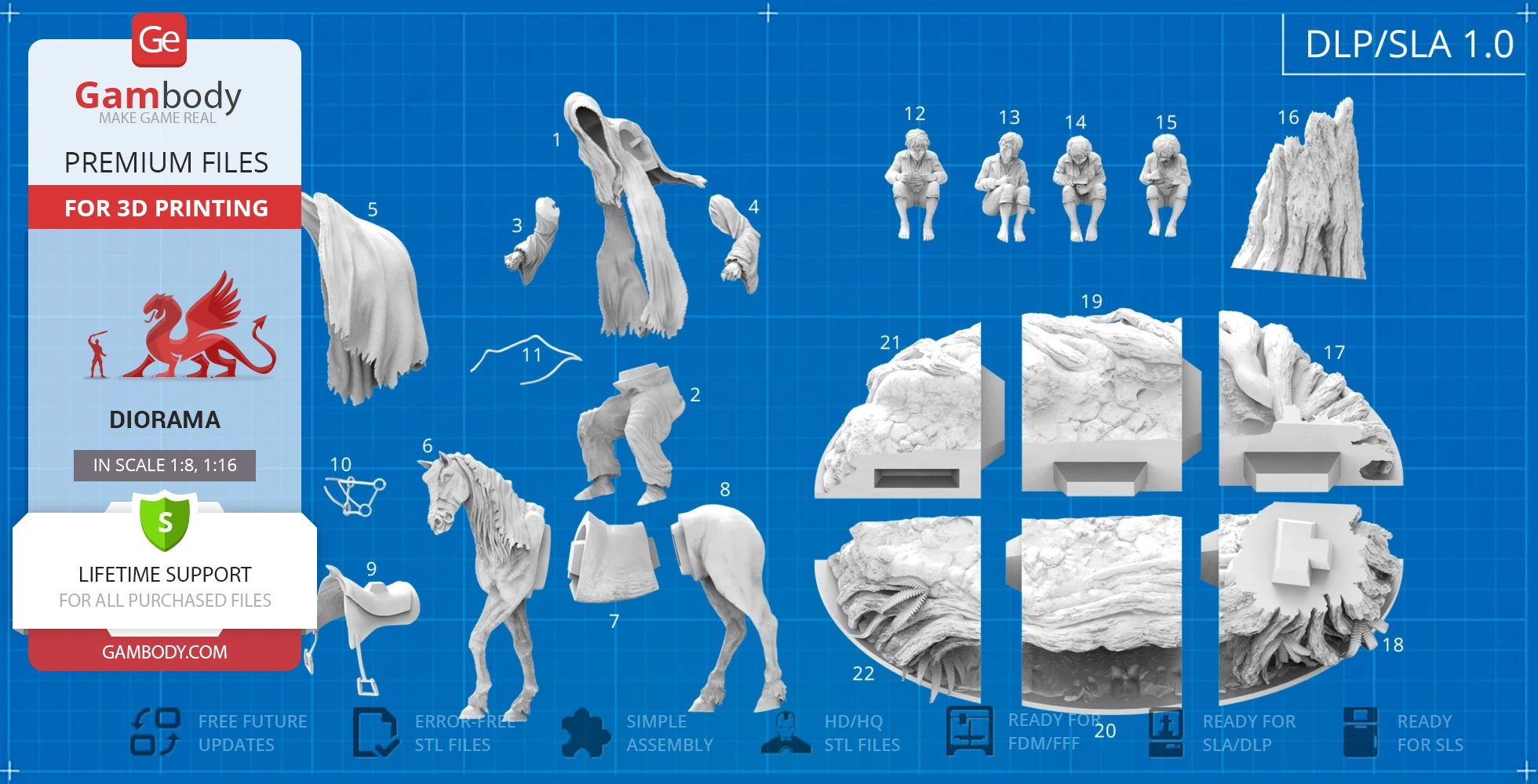
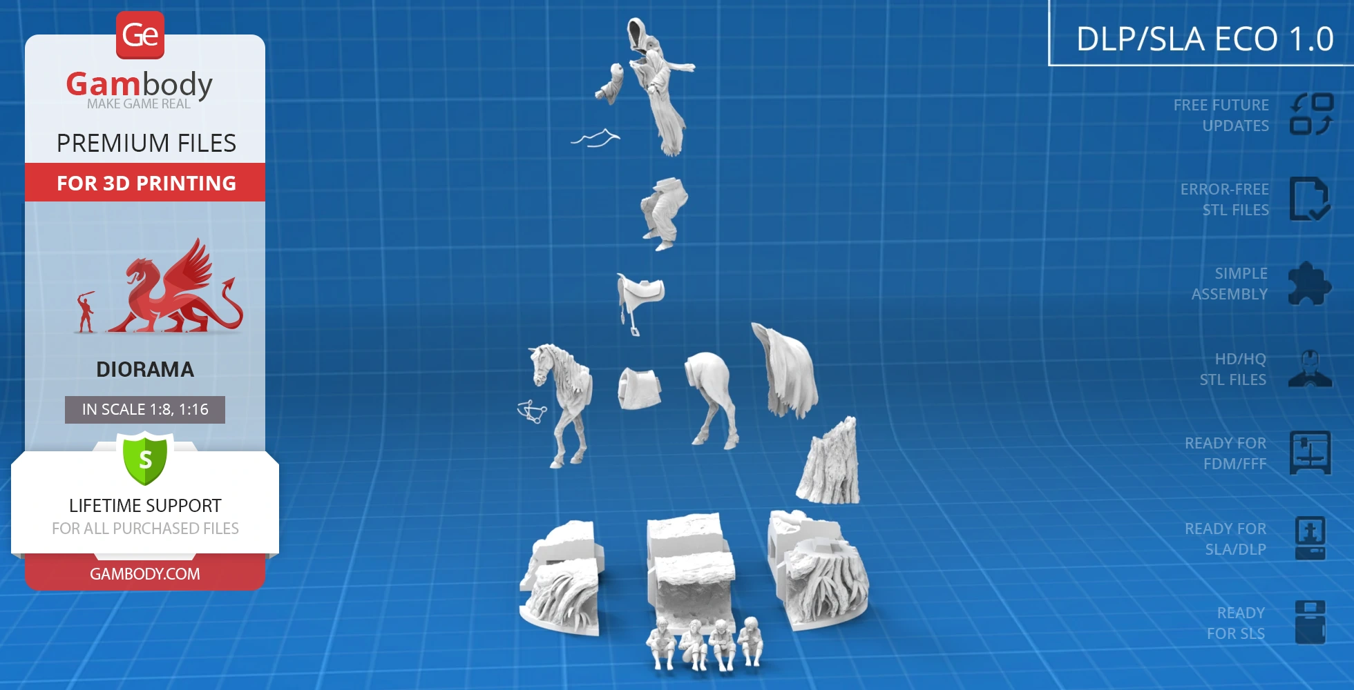
DLP/SLA
Eco parts
Assembly method
Connectors
Features
The assembly parts are connected using specially designed integrated connectors that fit securely into the corresponding slots. Optionally, for added strength and rigidity, the static assembly joints can be glued together;
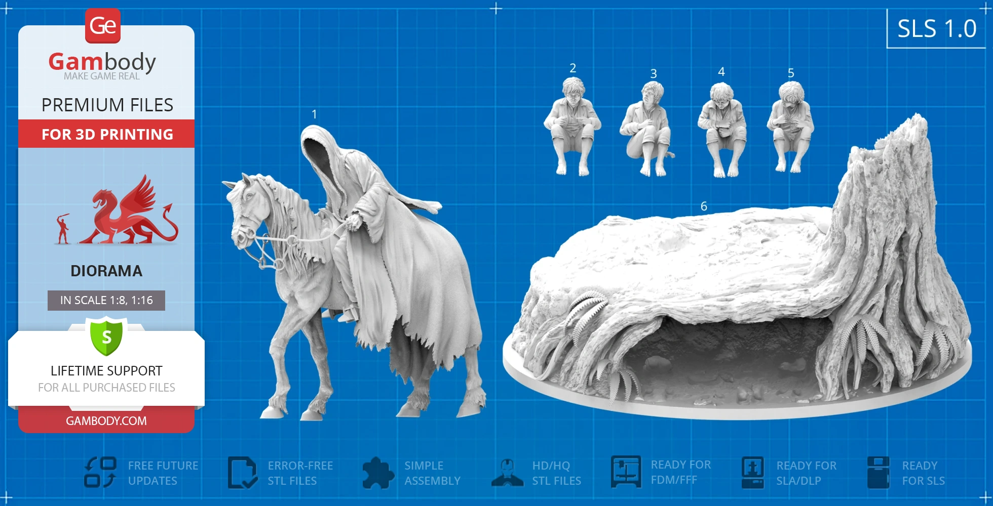
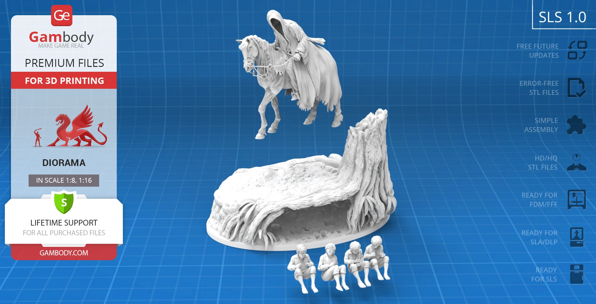
SLS
Assembly method
Connectors
Features
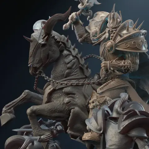
Contains 6 parts: solid Nazgul and Hobbits models separately from the base;
The assembly parts are connected using specially designed integrated connectors that fit securely into the corresponding slots. Optionally, for added strength and rigidity, the static assembly joints can be glued together;
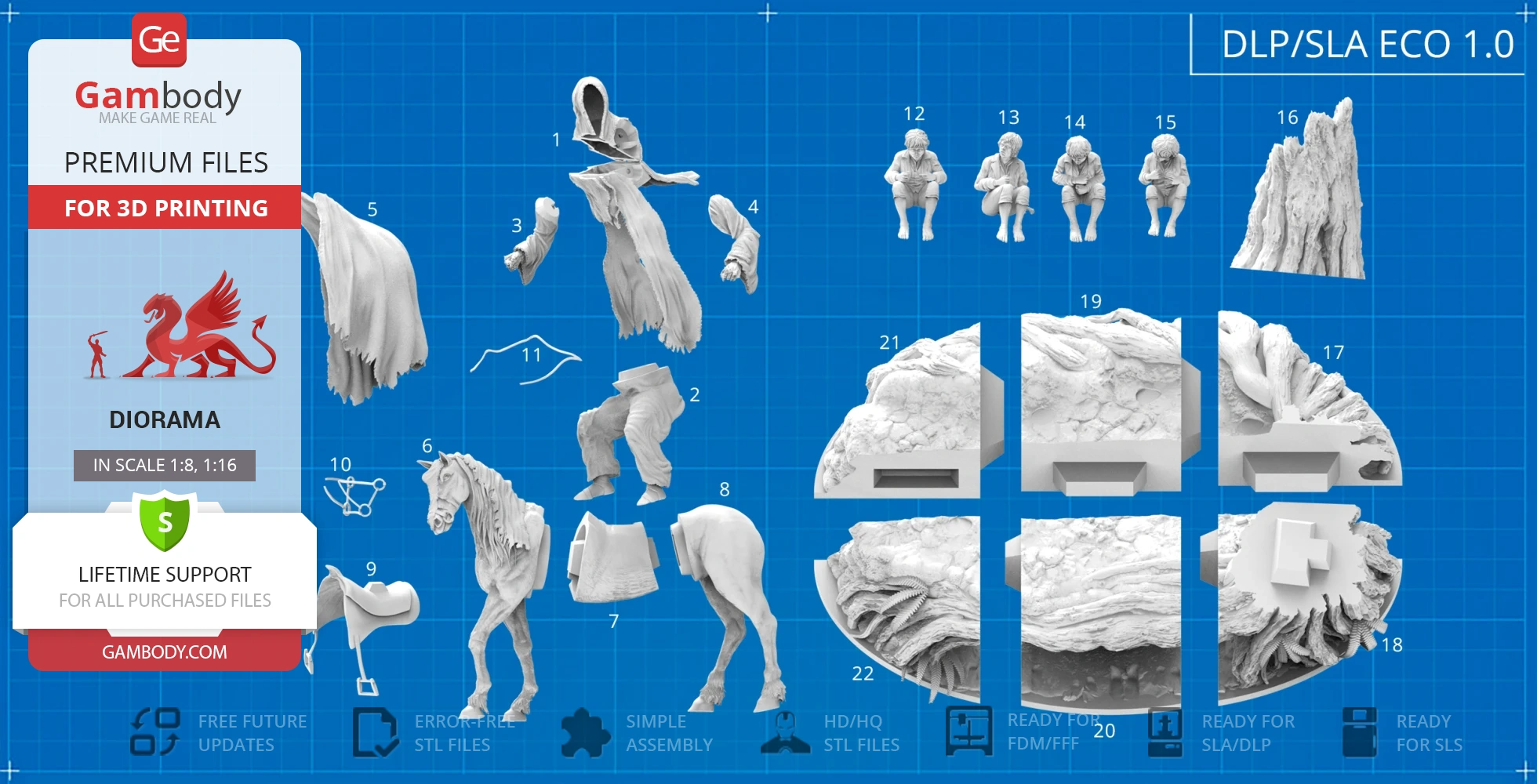
DLP/SLA
Eco parts
Assembly method
Connectors
Features
Contains some hollowed out parts to save resin;
The assembly parts are connected using specially designed integrated connectors that fit securely into the corresponding slots. Optionally, for added strength and rigidity, the static assembly joints can be glued together;
Additional details
Part of diorama
No
Special pack included
No
You can get the STL files of Nazgul & Hobbits Diorama for 3D Printing immediately after the purchase! Just click the green Buy button in the top-right corner of the model’s page. You can pay with PayPal or your credit card.
Watch the tutorial on how to assemble Nazgul & Hobbits 3D Printing Models in Diorama onGambody YouTube channel.
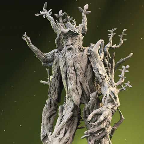
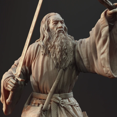
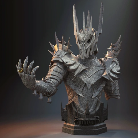
Also, you may like other Lord of the Rings 3D Printing Designs.
_______
FAQ:
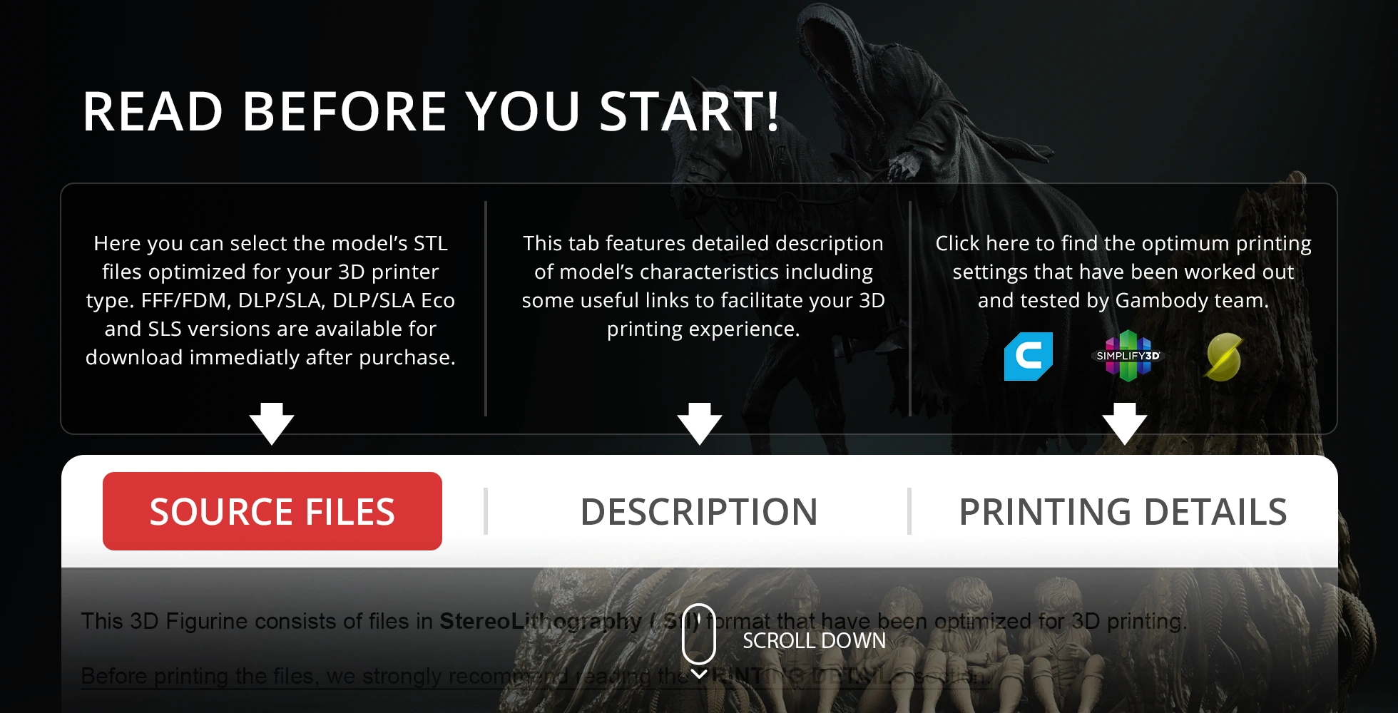
This 3D model comes with StereoLithography (.STL) files optimized for 3D printing. You'll get digital files, not a physical product
Before printing, take a look at Printing Details for recommended settings and tips to achieve better results.
Nazgul & Hobbits in Diorama 3D Printer Files | Assembly includes 3 version(s) for the supported 3D printer type(s): FFF/FDM, DLP/SLA, SLS. Files are available for download after purchase.
See the Description and Specifications sections for more details about this model.
3D model history
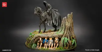
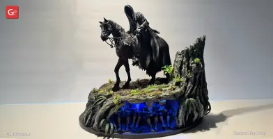
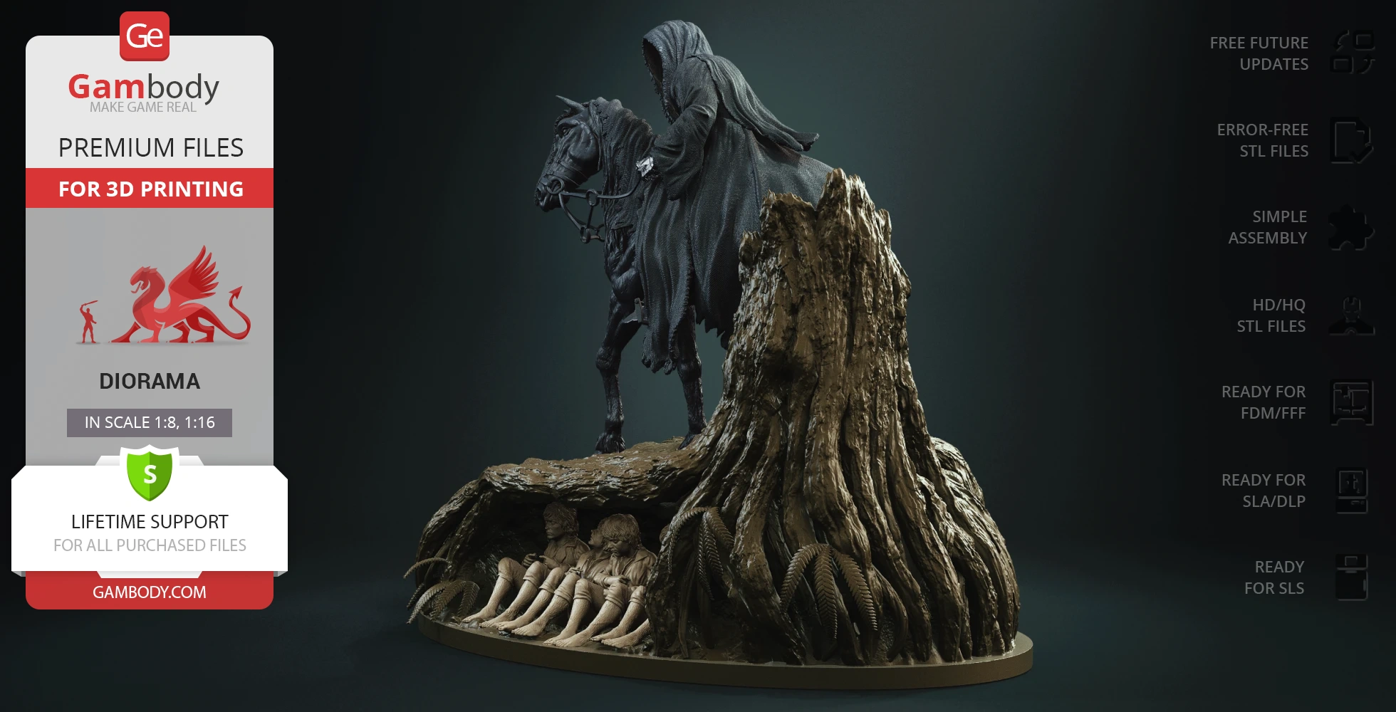
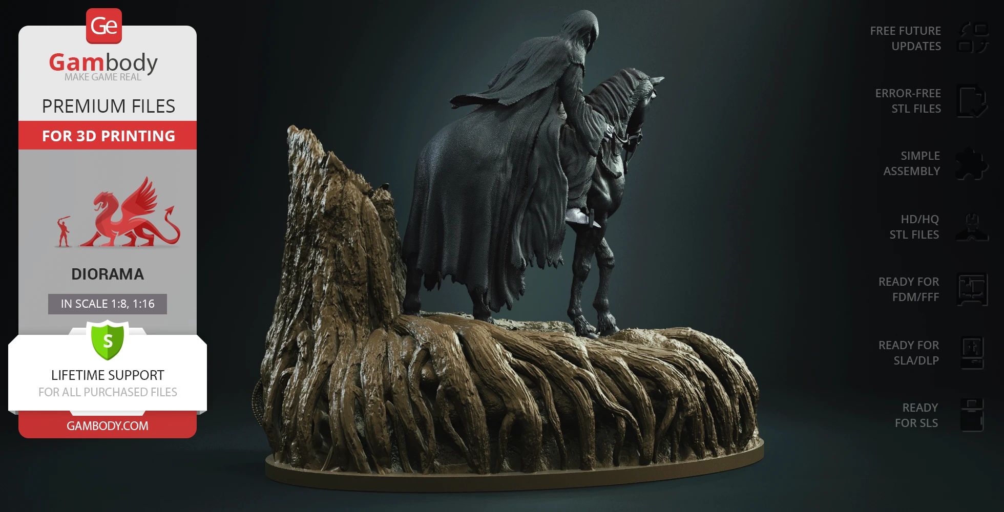
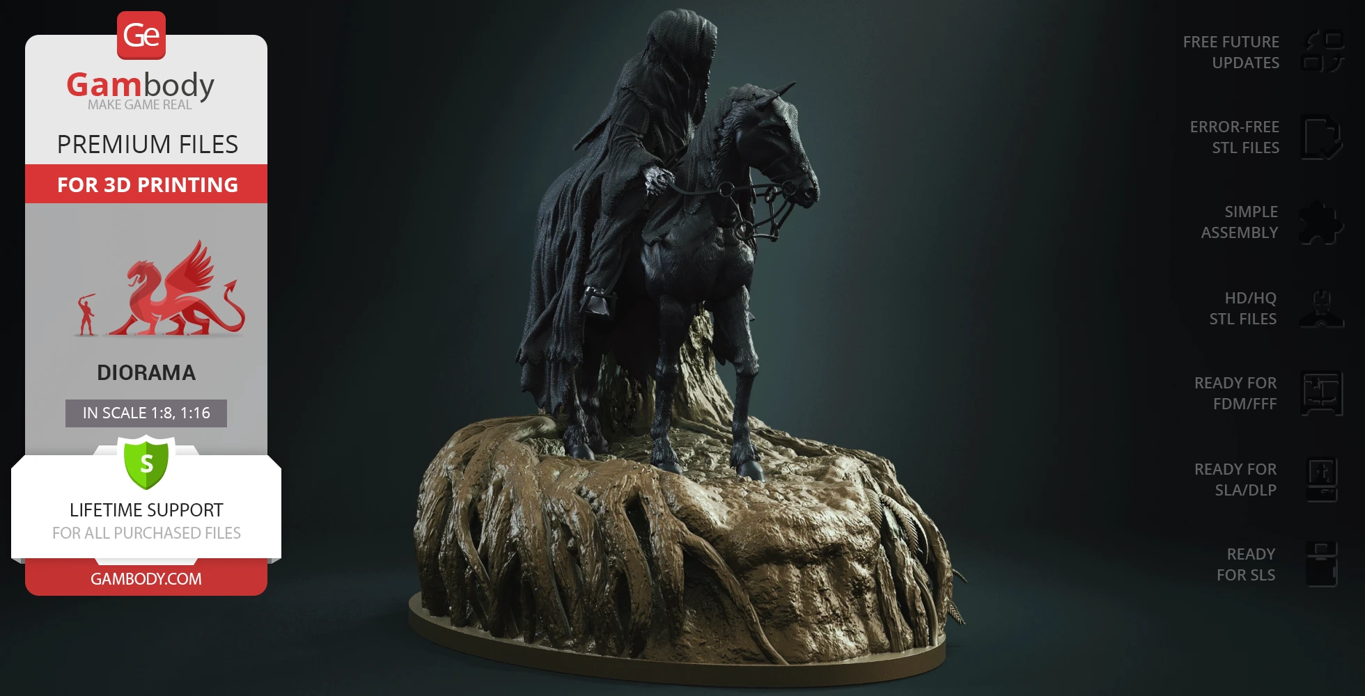
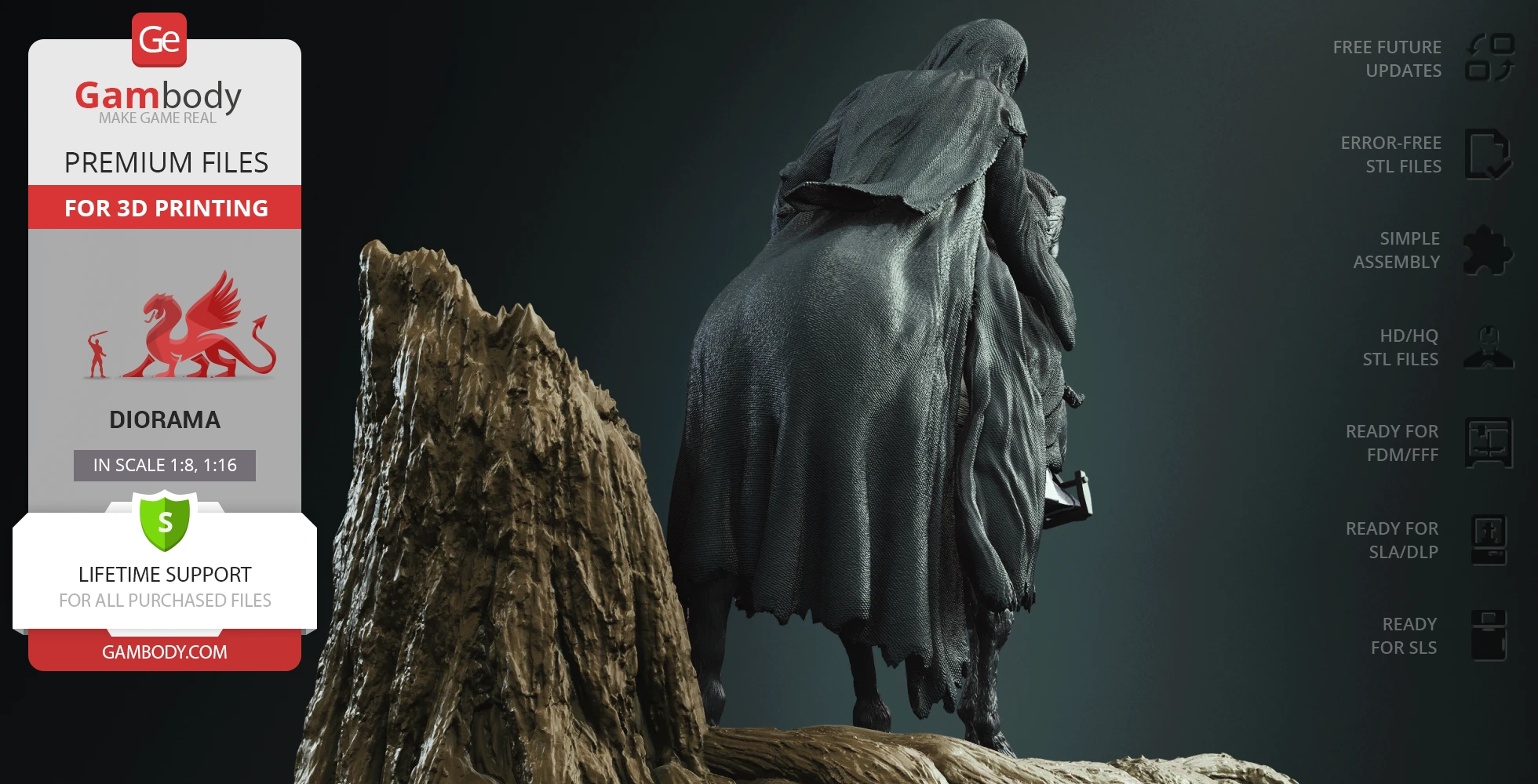
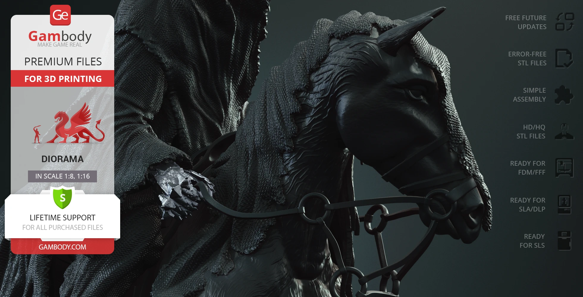
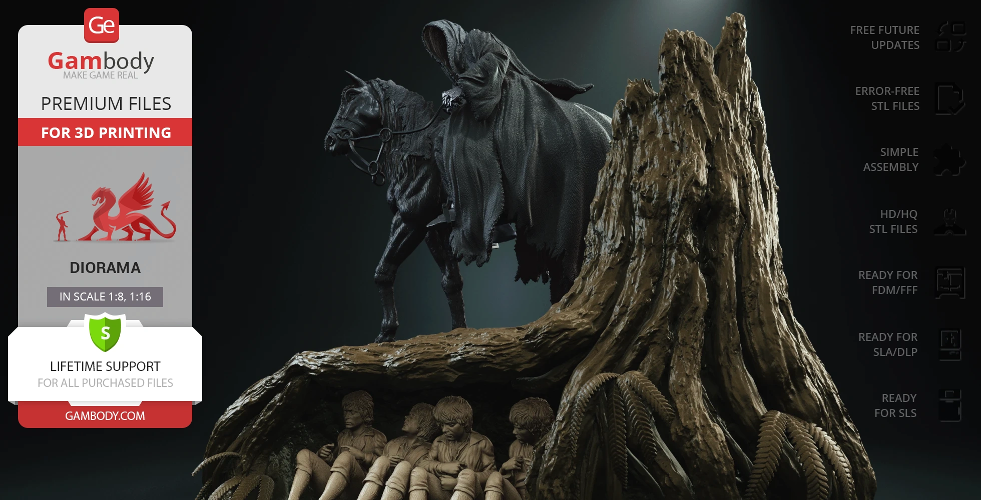
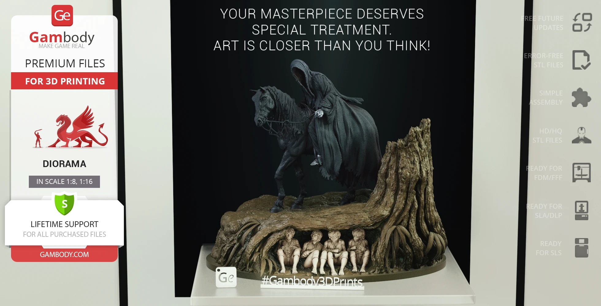
The Lord of the Rings trilogy is a classic of the fantasy genre and, probably, is the most-known film in the world. The adventures of Frodo Baggins and other Fellowship of the Ring members pursued by the nine Black Riders during the mission to destroy the One Ring are full of tense plot twists and vivid scenes. The episode which shows Nazgul chasing hobbits keeps the audience in suspense and makes everyone empathize with the heroes every minute.
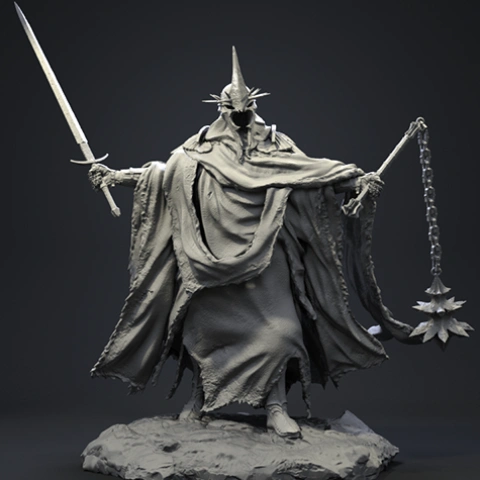
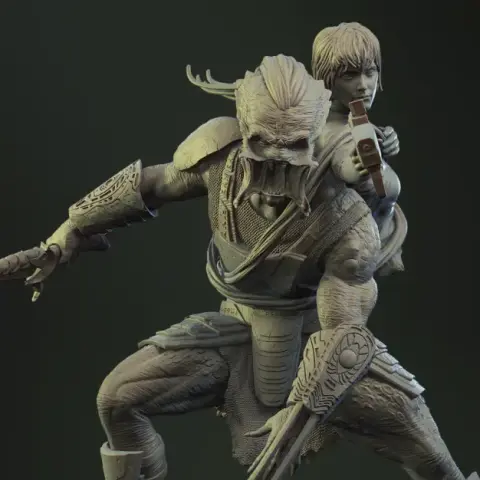
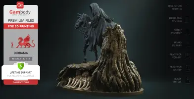
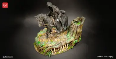
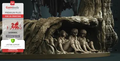
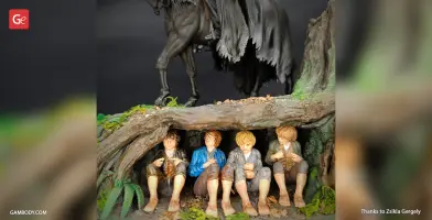
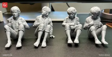
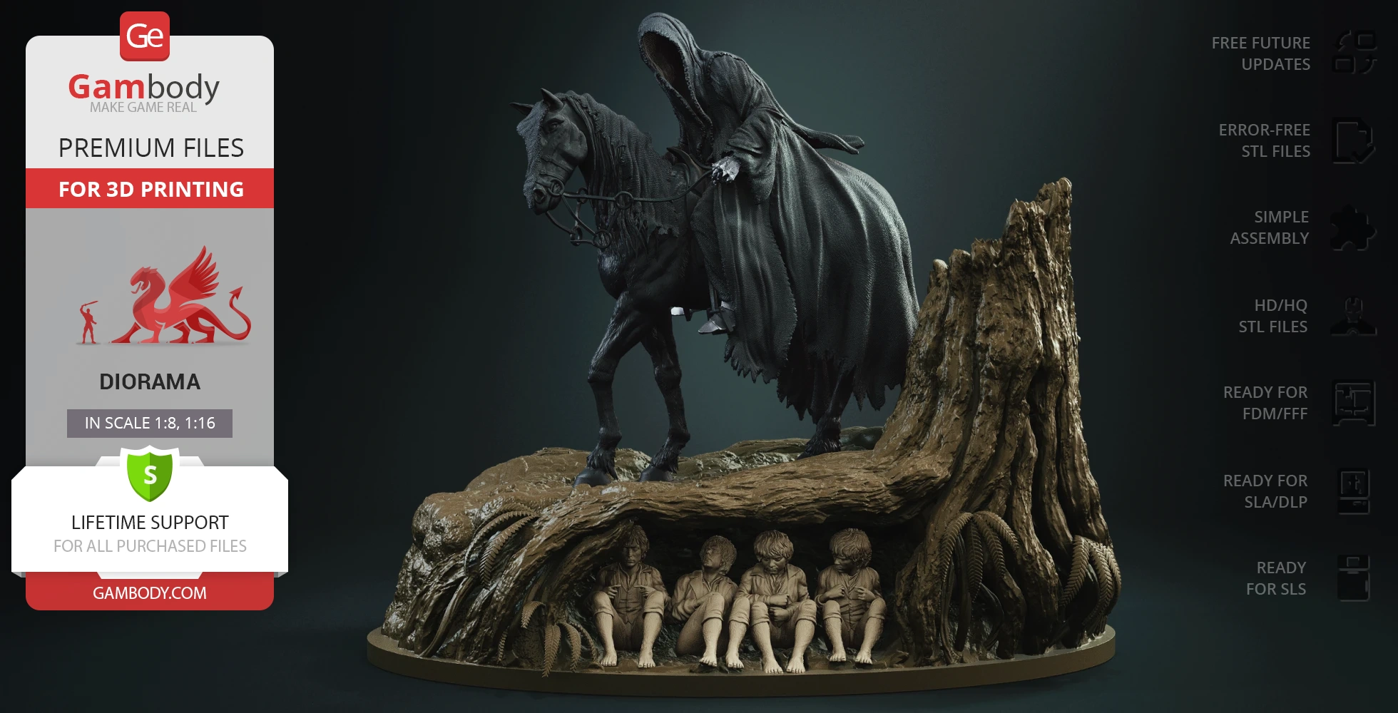
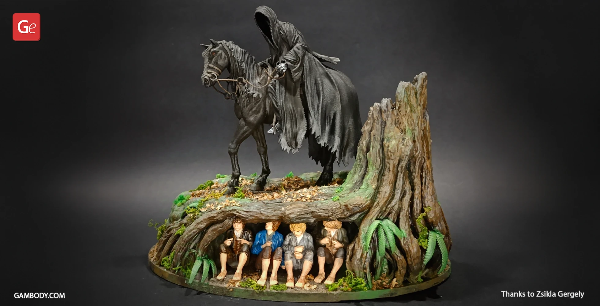
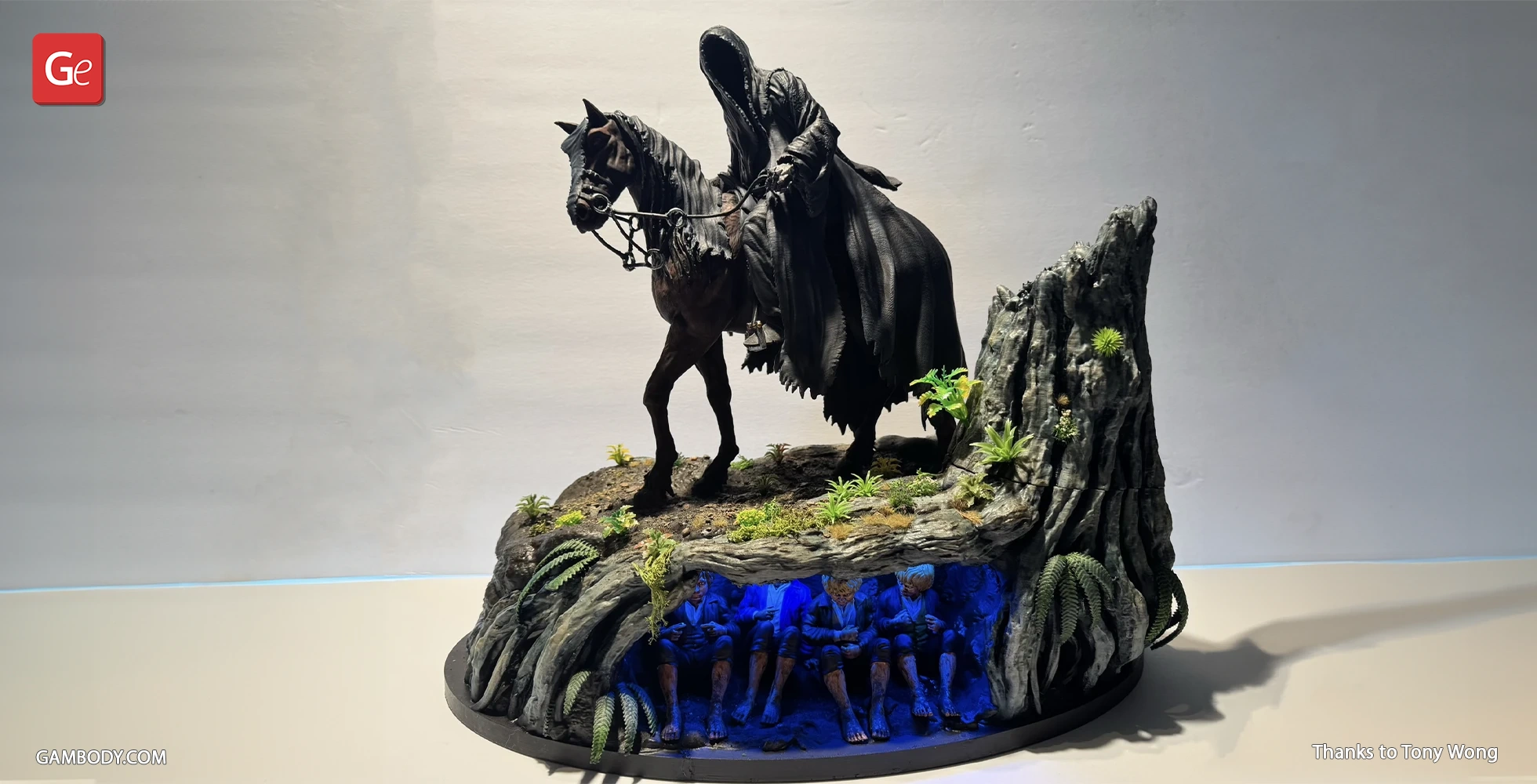
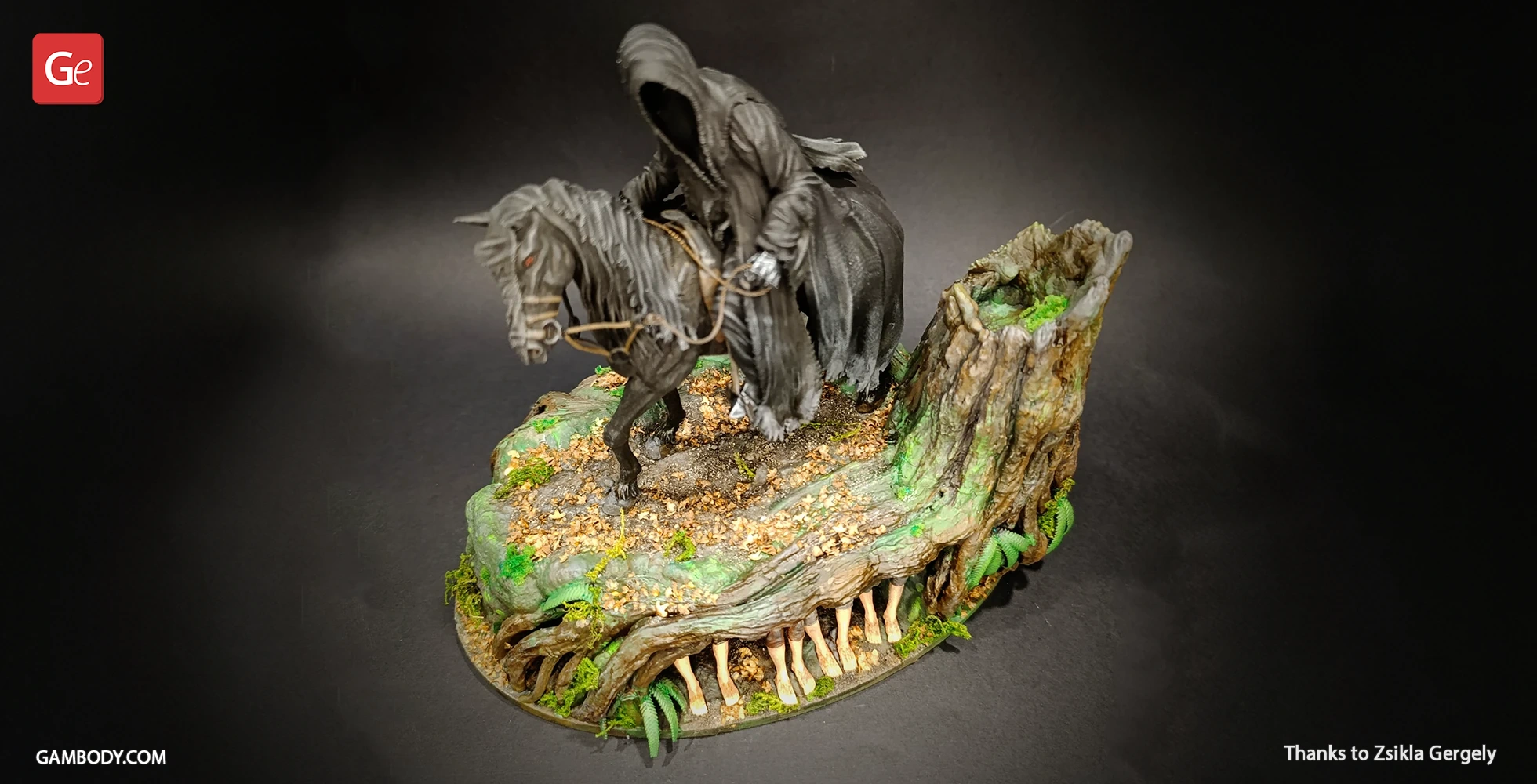
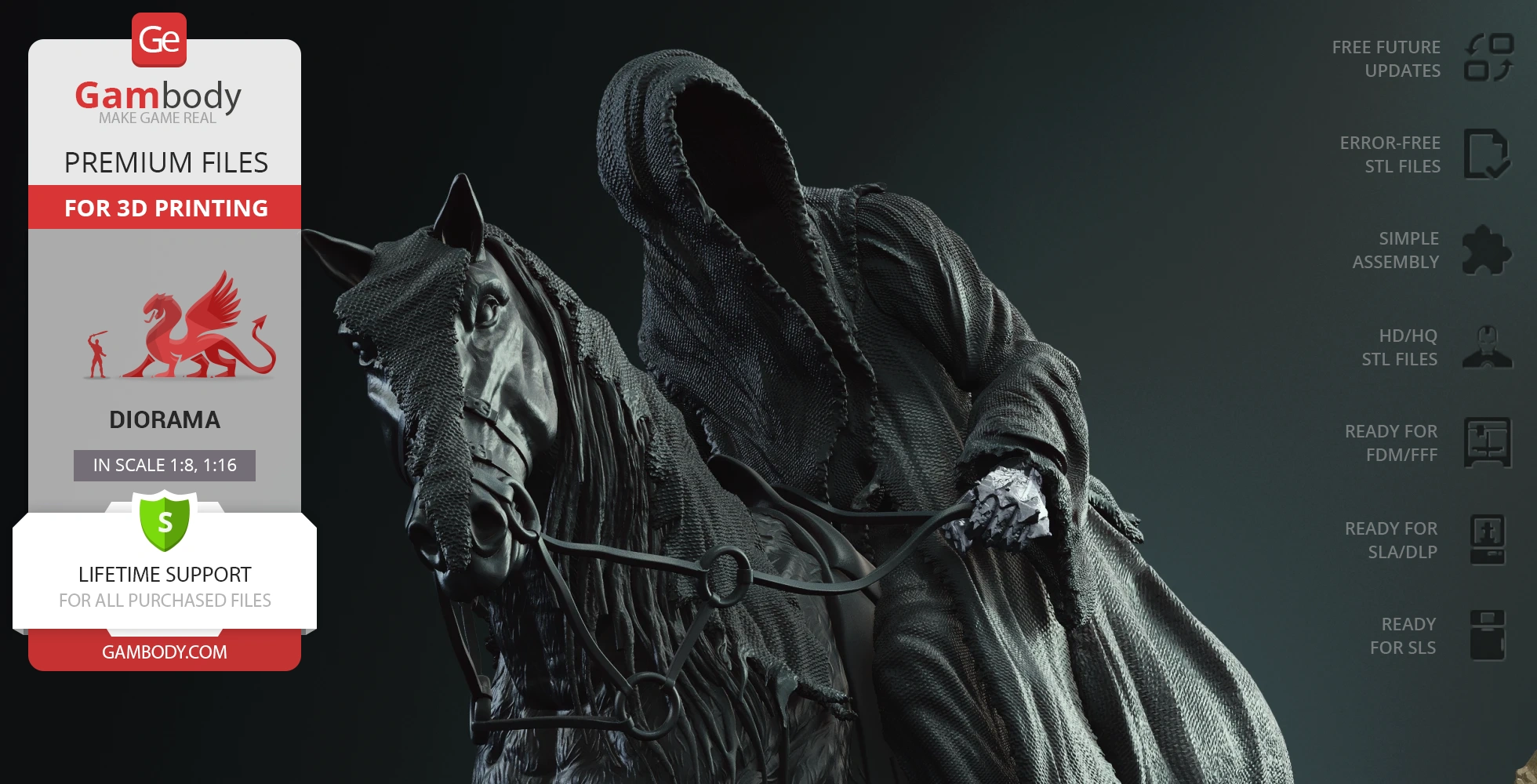
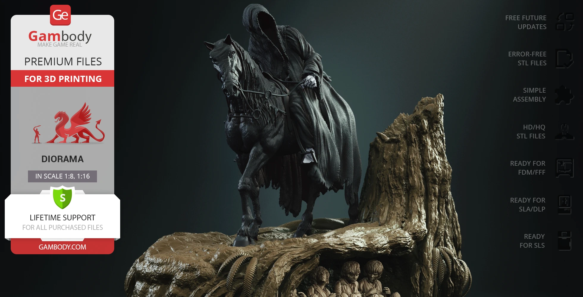
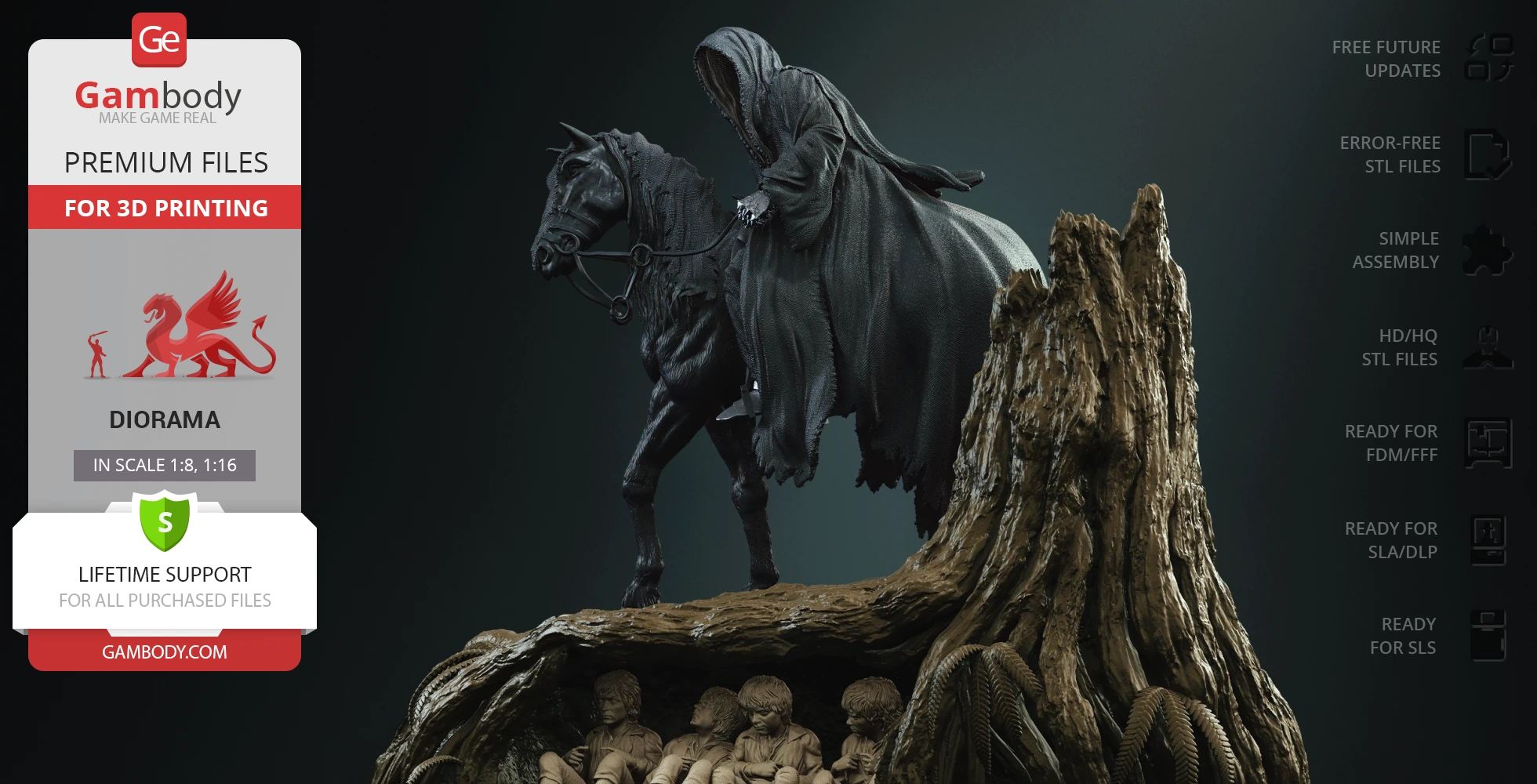
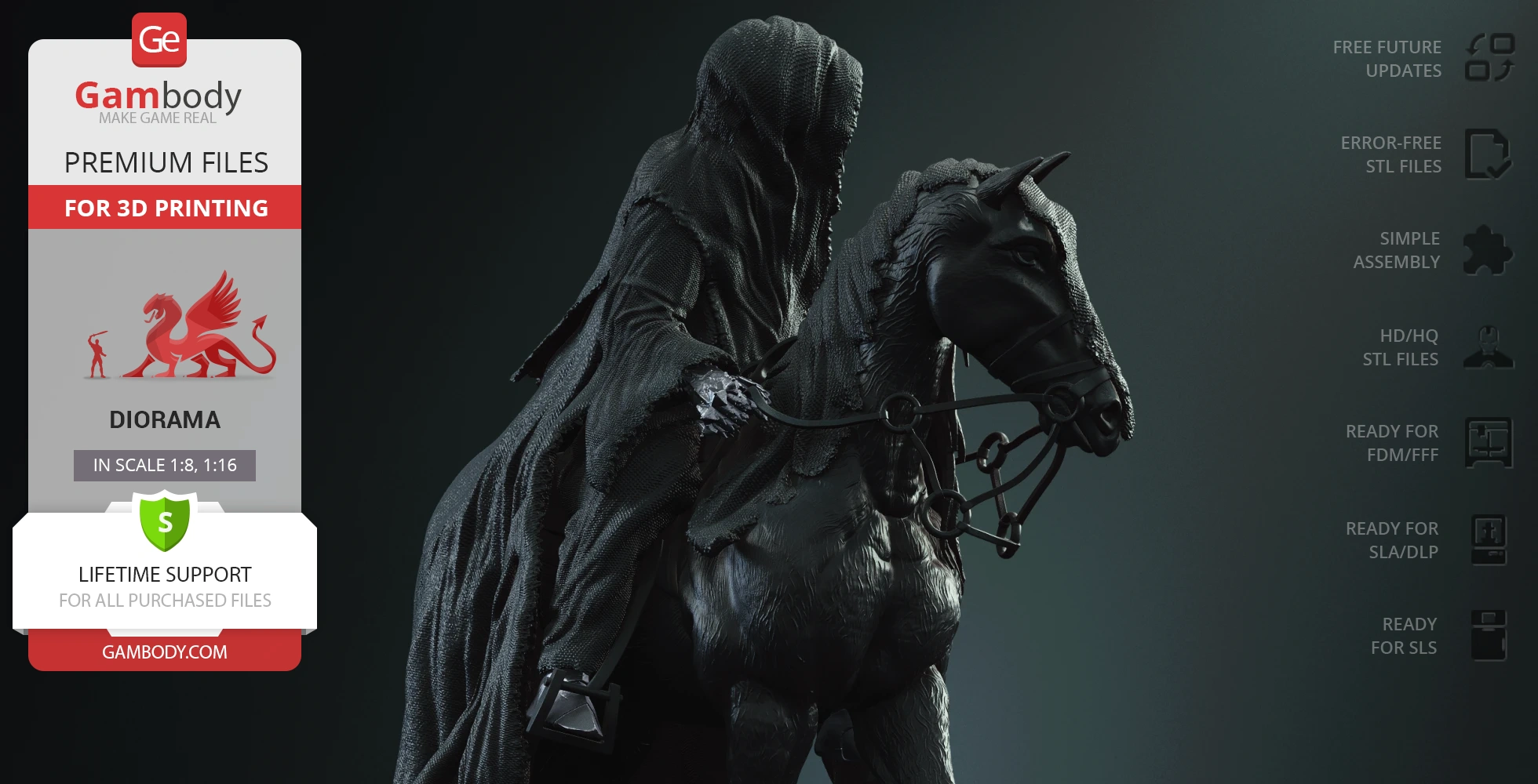
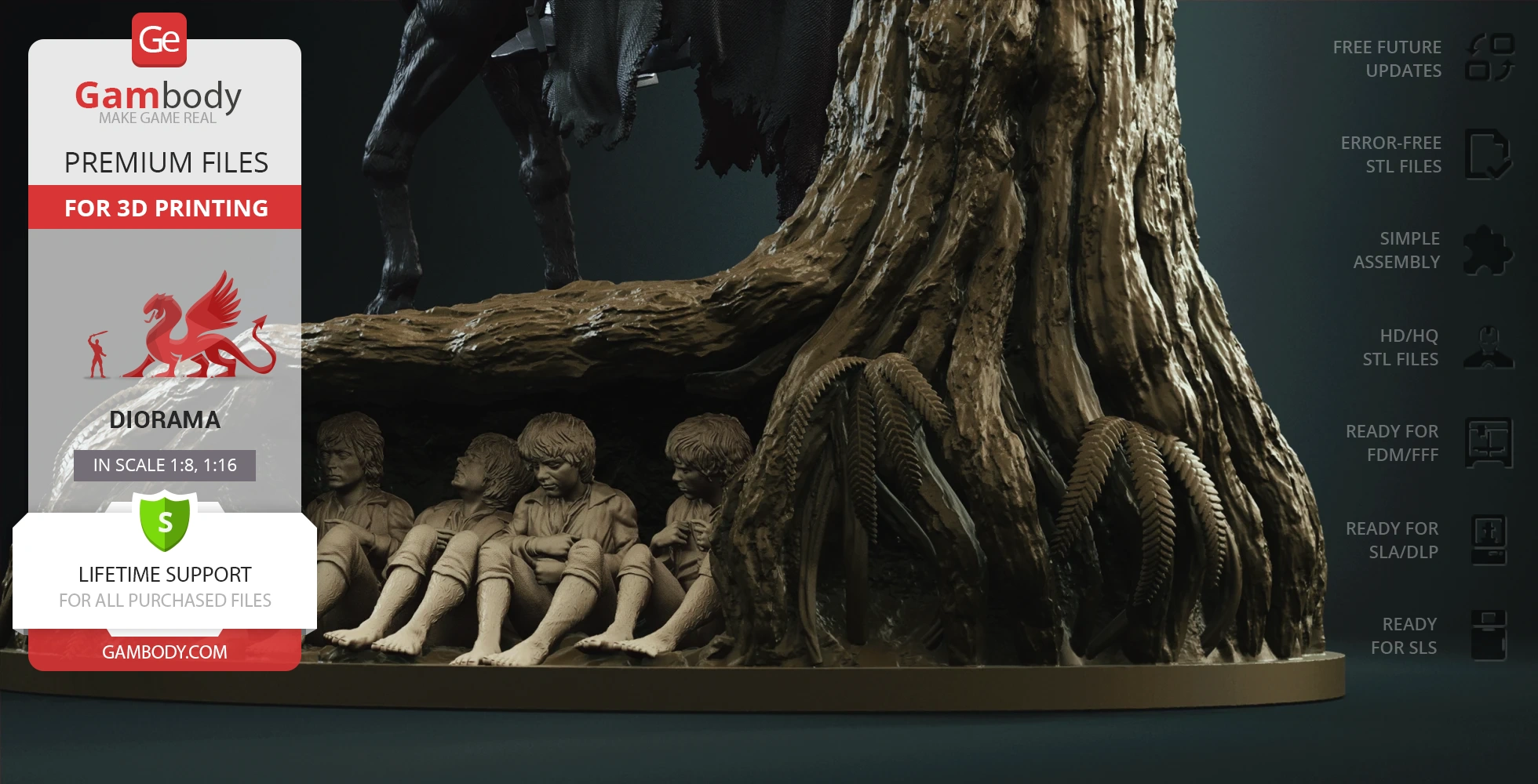
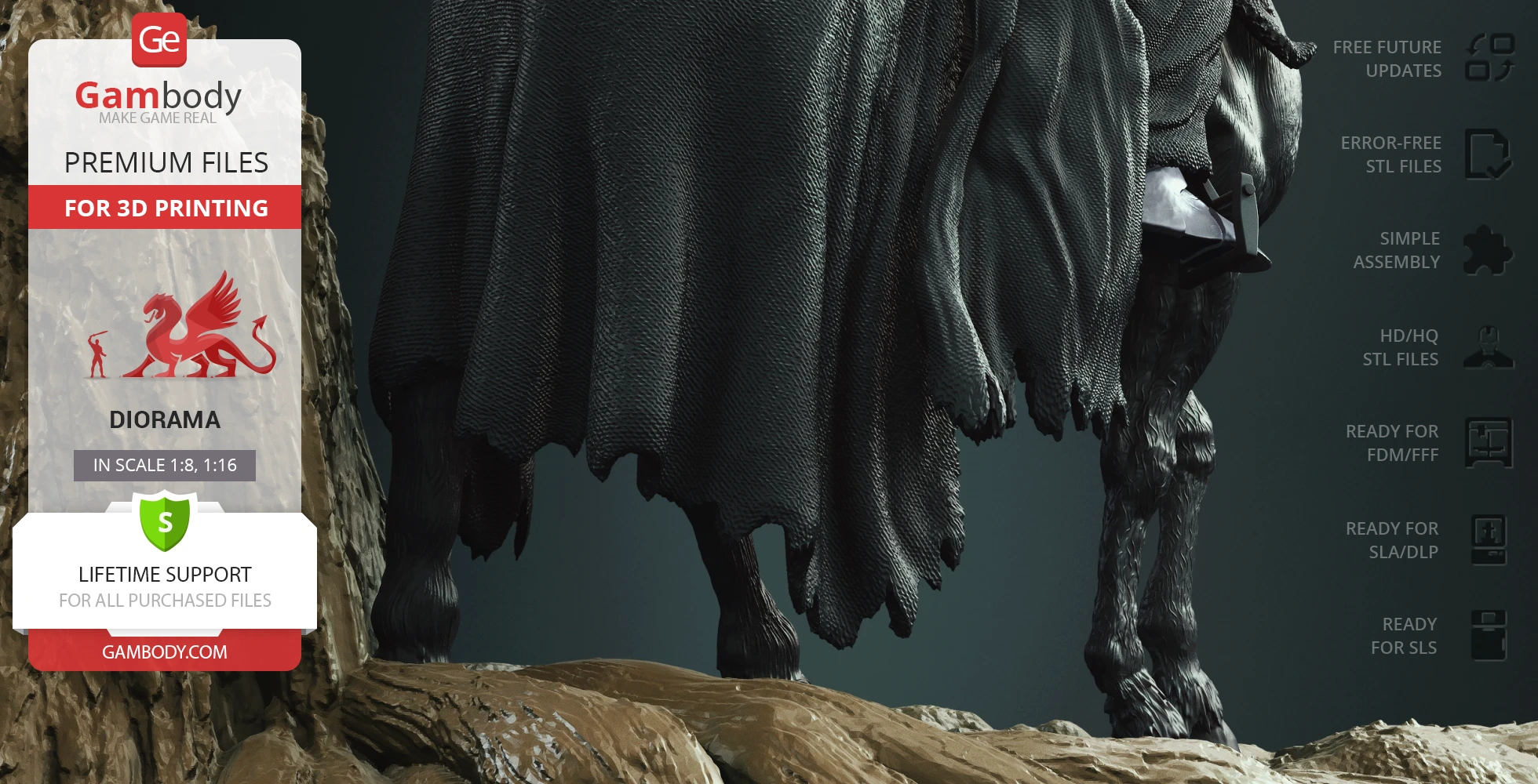
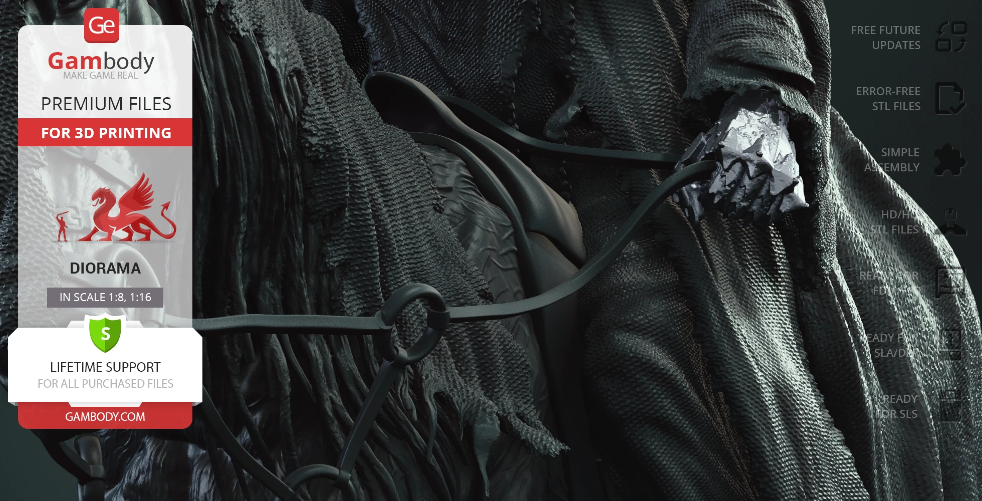
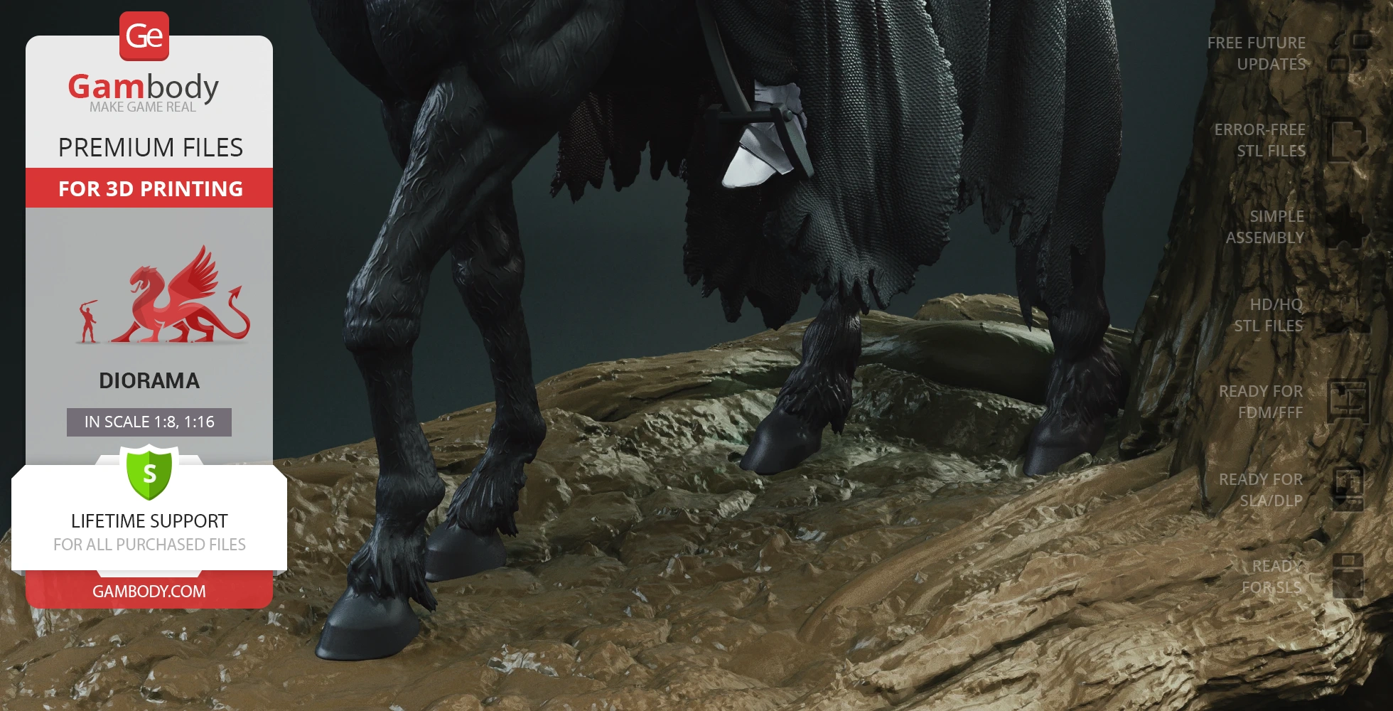
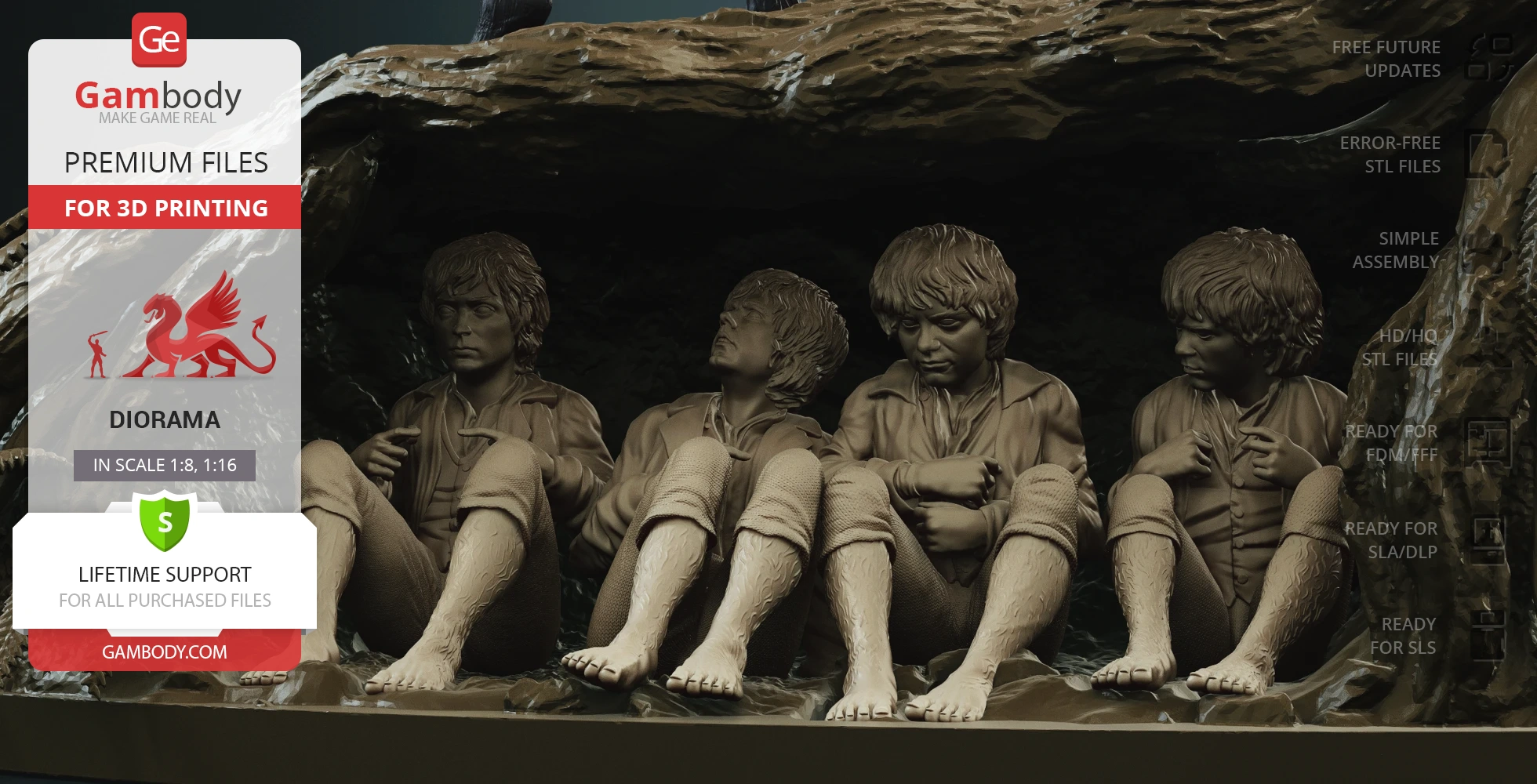
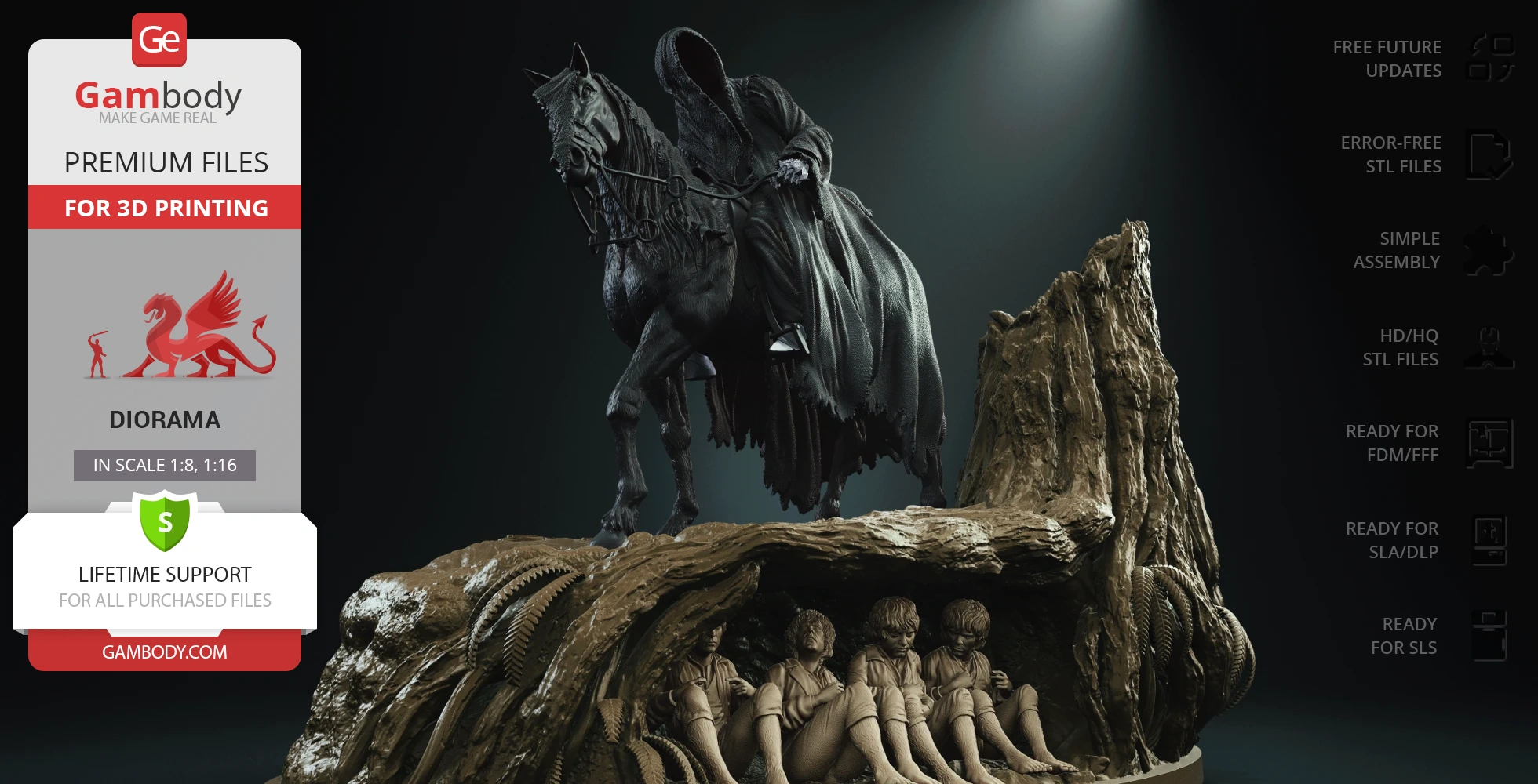
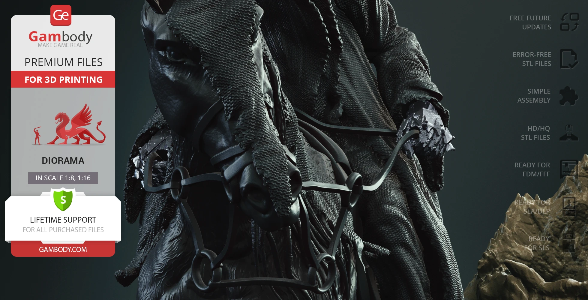
The author of the Nazgul & Hobbits diorama was particularly inspired by the scene of the chase in the Old Forest where hobbits were hiding from the black rider in the tree roots and embodied the moment in the form of a 3D model to print. The Nazgul silhouette is designed with great precision and looks very authentic in the chosen posture where the servant of Sauron is depicted holding the reins of his horse and peering into the forest thickets. The 3D models of the hobbits deserve special attention as they look very realistic and their facial expressions perfectly convey the emotions from happening. These STL files for 3D printing are the dream of every LOTR fan and you can already get them for yourself, don’t delay!
3D printing model features
Model-specific features:
- Captures a tense moment from The Lord of the Rings, depicting a Nazgul Black Rider chasing Hobbits, inspired by the Old Forest scene;
- Features a precisely designed Nazgul silhouette in a commanding posture, holding a horse reins and peering into the thicket, alongside highly realistic Hobbits with expressive facial features.
Printing & assembly details:
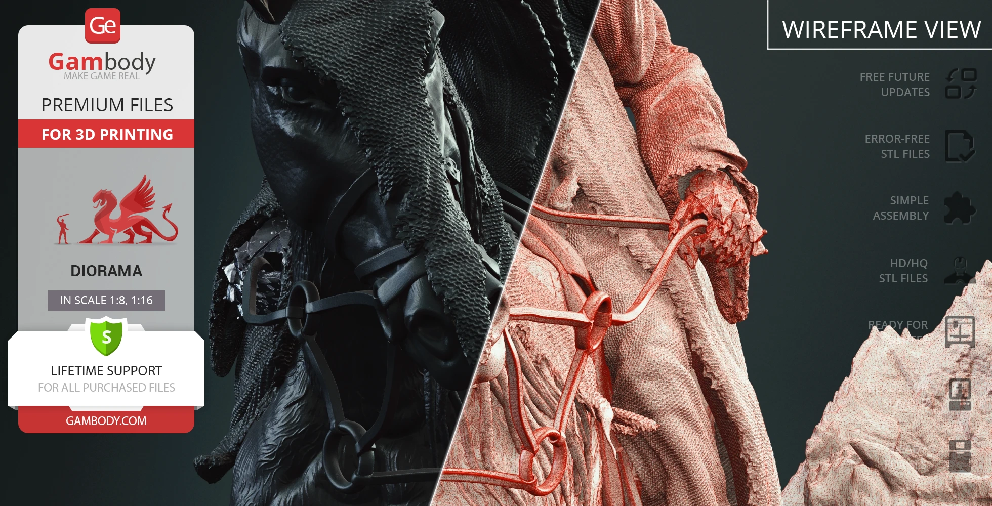
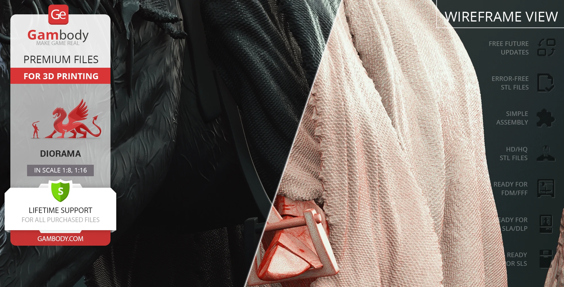
- Provided as error-free STL files compatible with most 3D printers;
- Optimized part division minimizes support material and ensures smooth surface detail;
- The assembly parts in the FFF/FDM version come in the recommended print orientations for easy bed placement;
- Assembly manual in PDF and video formats is included for both FFF/FDM and DLP/SLA versions;
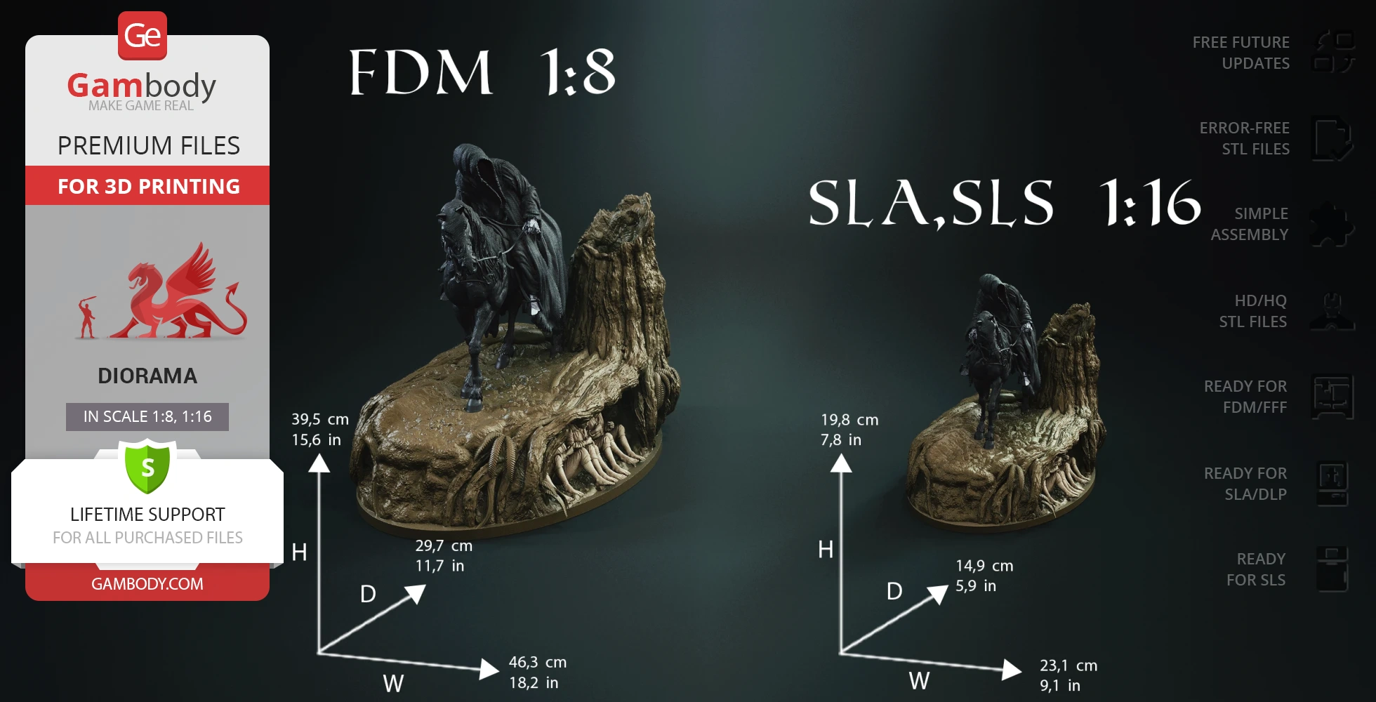
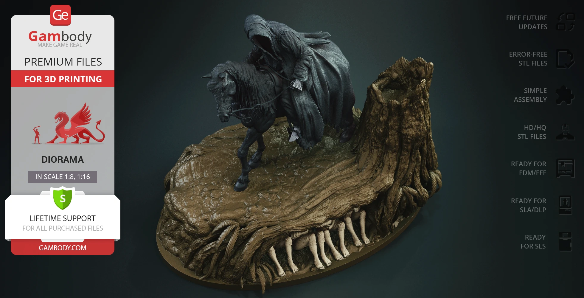
- The model is available in recommended scales of 1:8 for the FFF/FDM version and 1:16 for the DLP/SLA/SLS versions, based on the Nazgul's height.
What will you get after purchase?
- 4 versions of Nazgul & Hobbits STL files for FFF/FDM, DLP/SLA, DLP/SLA Eco, SLS - files for all versions are available for download after the purchase;
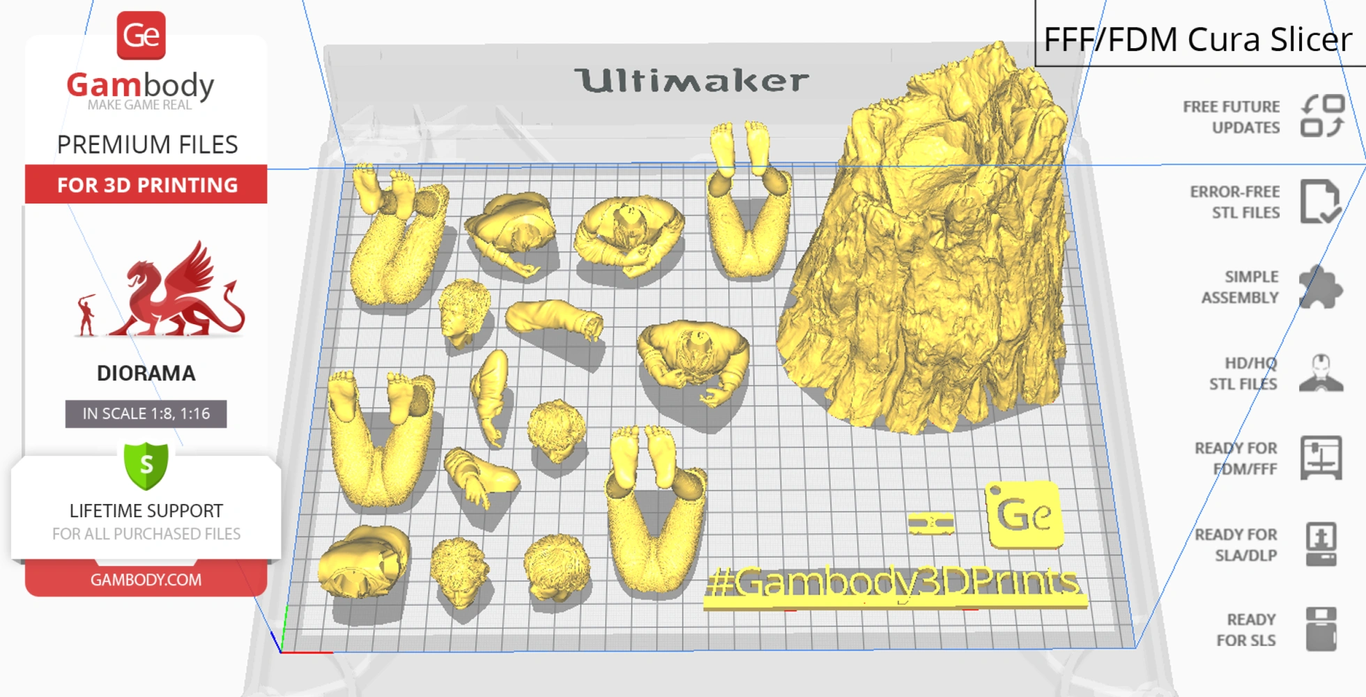
- STL files of high-poly Nazgul & Hobbits diorama for 3D printing consist of 96 files;
- Sizes for:
- FFF/FDM: 463 mm wide, 395 mm high, 297 mm deep;
- DLP/SLA/SLS: 231 mm wide, 198 mm high, 149 mm deep;
- Assembly Manual for FFF/FDM 1.0 and DLP/SLA 1.0 versions in PDF and video formats;
- Detailed settings that we provide as a recommendation for Bambu Studio, Cura, Orca Slicer, PrusaSlicer, Simplify3D, and Slic3r for the best print;
- Full technical support from the Gambody Support Team.
Average customer rating (12 reviews)
4.4
Ratings breakdown
Click a star rating to filter reviews
Overall experience
Level of detail in the model
4.4
Model cut quality and assembly guide
4.4
Clarity and accuracy of the model page
4.5
Level of detail in the model
3.1
Model cut quality and assembly guide
2.9
Clarity and accuracy of the model page
4
Modello Migliorabile, tutto sommato ne vale la pena
Regarding the joints: slight inconsistencies in fit can occur when printing with resin due to factors like shrinkage, exposure settings, or individual printer calibration. Even with high-resolution machines, small variations in curing can cause tighter connections, which is why some light sanding or minor adjustment may be needed during assembly.
We’re very happy to hear the result was worth the effort in the end, and your insights can be incredibly helpful to other makers. If you’d like, we warmly invite you to share your experience and photos in our Facebook Community, where many 3D enthusiasts enjoy exchanging tips and seeing how others approached the same model: https://www.facebook.com/groups/183216945475583/.
If you ever have questions, need printing advice, or want recommendations for future projects, please feel free to reach out. We’re always here to help!
Level of detail in the model
5
Model cut quality and assembly guide
5
Clarity and accuracy of the model page
5
Level of detail in the model
4
Model cut quality and assembly guide
4
Clarity and accuracy of the model page
4
Level of detail in the model
5
Model cut quality and assembly guide
5
Clarity and accuracy of the model page
5
Level of detail in the model
4
Model cut quality and assembly guide
4
Clarity and accuracy of the model page
4
Level of detail in the model
5
Model cut quality and assembly guide
5
Clarity and accuracy of the model page
5
Level of detail in the model
5
Model cut quality and assembly guide
5
Clarity and accuracy of the model page
5
Level of detail in the model
2
Model cut quality and assembly guide
2
Clarity and accuracy of the model page
2
Level of detail in the model
5
Model cut quality and assembly guide
5
Clarity and accuracy of the model page
5
Level of detail in the model
5
Model cut quality and assembly guide
5
Clarity and accuracy of the model page
5
Level of detail in the model
5
Model cut quality and assembly guide
5
Clarity and accuracy of the model page
5
Level of detail in the model
5
Model cut quality and assembly guide
5
Clarity and accuracy of the model page
5
Below you'll find detailed slicing settings for Bambu Studio 2.0+, Orca Slicer 2.0+, UltiMaker Cura 5.0+, PrusaSlicer 2.0+, Slic3r 1.3+, Simplify3D 5.0+ to help you get the best results when printing this model. These settings are optimized specifically for this 3D model, but please note they may need slight adjustments depending on your printer or filament. When in doubt, refer to your printer's user manual.
To avoid printing issues and achieve the best quality, we highly recommend applying the following settings:
For better quality use 0.12 mm layer height, for fast printing use 0.2 mm layer height. For pins and the Ge connectors, use 0.2 layer height.
120-150% of your Layer Height
But you can paint the seam if you want.
You have to calibrate this parameter
You have to calibrate this parameter
You have to calibrate this parameter
For pins and power elements of the structure, such as the vehicle frame, use 3 loop
Disabled for vehicles and enabled for characters
For 0,2 Layer Height
The parameters in this tab vary greatly, it all depends on the quality of your printer. For example, if you have a classic Ender3, stick to the minimum parameters, but if you have a newer printer, for example Anycubic cobra 3 v2, you can select the maximum recommended values
Settings for advanced users, change these parameters only if you have sufficient 3D printing expertise
Enable this parameter if your model requires supports
We also recommend placing and removing supports manually in some places using special button
1-2 loops for more thick support
Top Z distance = 1-1.3 layer Height. If the supports are hard to remove, try increasing this setting by 0.1-0,4 mm
Bottom Z distance = 1-1.3 layer Height. If the supports are hard to remove, try increasing this setting by 0.1-0,4 mm
You have to calibrate this parameter which one is better for your filament
Increase this parameter if the supports are hard to remove from walls
For PLA and PETG filament types
5-8 mm is optional for small prints that have bad adhesion to the build plate
You have to calibrate this parameter
Read the description on your filament roll
Read the description on your filament roll and increase this parameter for fast printers
Read the description on your filament roll and increase this parameter for fast printers
For better quality use 0.12 mm layer height, for fast printing use 0.2 mm layer height. For pins and the Ge connectors, use 0.2 layer height.
120-150% of your Layer Height
But you can paint the seam if you want.
0.01-0.05 You have to calibrate this parameter
0.01-0.05 You have to calibrate this parameter
0.1-0.2 You have to calibrate this parameter
For pins and power elements of the structure, such as the vehicle frame, use 3 loop
Disabled for vehicles and ships, enabled for characters
For 0,2 Layer Height
For 0,2 Layer Height
The parameters in this tab vary greatly, it all depends on the quality of your printer. For example, if you have a classic Ender3, stick to the minimum parameters, but if you have a newer printer, for example, Anycubic Kobra 3 Or Bambulab A1, you can select the maximum recommended values.
Settings for advanced users, change these parameters only if you have sufficient 3D printing expertise
Enable this parameter if your model requires supports
We also recommend placing and removing supports manually in some places using special button
Top Z distance = 1-1.3 layer Height. If the supports are hard to remove, try increasing this setting by 0.1-0,4 mm
Bottom Z distance = 1-1.3 layer Height. If the supports are hard to remove, try increasing this setting by 0.1-0,4 mm
Increase this parameter if the supports are hard to remove from walls
For PLA and PETG filament types
5-8 mm is optional for small prints that have bad adhesion to the build plate
Read the description on your filament roll
Read the description on your filament roll and increase this parameter for fast printers
You have to calibrate this parameter
Read the description on your filament roll and increase this parameter for fast printers
Read the description on your filament roll
This field is filled in according to your printer specifications when you add it to the slicer.
You can add custom G-code here for the start and end of the print. However, be careful - this is for advanced users only!
You have to calibrate your printer using Ge retraction test models
Retraction Length: For direct-drive setups use 0.5 mm to 2.5 mm; for Bowden extruders use 5 to 7 mm
This is how fast the filament is pulled back—40-60 mm/s for direct drive and 30-50 mm/s for Bowden setups.
You have to calibrate this parameter: Reduce it until the printer starts to hit the parts with the nozzle during printing, then increase it by 0.2.
For better quality use 0.12 mm layer height, for fast printing use 0.2 mm layer height. For pins and the Ge connectors, use 0.2 layer height.
120-150% of your Layer Height
To increase the strength of the print parts, use wall line count: 3
For pins and connectors use 50% Infill
These parameters are for standard PLA plastic. If you are using a different type of plastic, check the printing temperature recommended by the manufacturer. Also, read the description on your filament spool. For fast printers, add +30 °C to the current parameters.
The parameters in this tab vary greatly, it all depends on the quality of your printer. For example, if you have a classic Ender3, stick to the minimum parameters, but if you have a newer printer, for example Anycubic cobra 3 v3, you can select the maximum recommended values
Settings for advanced users, change these parameters only if you have sufficient 3D printing expertise.
You need to calibrate this parameter using Gambody test models. These values are average values for a Direct Drive extruder; for a Bowden extruder, the values should be increased.
You need to calibrate this parameter using Gambody test models. These values are average values for a Direct Drive extruder; for a Bowden extruder, the values should be increased.
Use this value other than 0 if your nozzle catches on the internal infill during travel moves. Try to keep this value as low as possible in height.
Use normal supports to support large, straight surfaces (most mechanical or technical parts).
You have to calibrate this parameter according to the capabilities of your printer and your filament, using a Gambody test models.
Use 1 instead of 0 if your supports are thin and tall. They will be harder to remove, but much stronger.
Top Z distance = 1-1.3 layer Height. If the supports are hard to remove, try increasing this setting by 0.1-0,4 mm
Increase this parameter if the supports are hard to remove from walls
Use tree supports to support complex objects, such as characters.
You have to calibrate this parameter according to the capabilities of your printer and your filament, using a Gambody test models.
Top Z distance = 1-1.3 layer Height. If the supports are hard to remove, try increasing this setting by 0.1-0,4 mm
Increase this parameter if the supports are hard to remove from walls
Use a skirt for all parts when printing on outdated printers.
Use a brim when printing thin but tall parts, as well as parts with a small bed adhesion area.
For better quality use 0.12 mm layer height, for fast printing use 0.2 mm layer height. For pins and the Ge connectors, use 0.2 layer height.
120-150% of your Layer Height
for 0.2 Layer Height
But you can paint the seam if you want.
(for PLA and PETG)
(5-8 mm is optional for small prints that have bad adhesion to the build plate)
Enable this parameter if your model requires supports
(45-50 degree)You have to calibrate this parameter according to the capabilities of your printer
and your filament, using a Gambody test models.
Top contact Z distance = 1-1.3 layer Height. If the supports are hard to remove, try
increasing this setting by 0.1-0,4 mm
Top contact Z distance = 1-1.3 layer Height. If the supports are hard to remove, try
increasing this setting by 0.1-0,4 mm
Increase this parameter if the supports are hard to remove from walls
The parameters in this tab vary greatly, it all depends on the quality of your printer. For example, if you have a classic Ender3, stick to the minimum parameters, but if you have a newer printer, for example Anycubic cobra 3 v3, you can select the maximum recommended values
Settings for advanced users, change these parameters only if you have sufficient 3D printing expertise. Use the minimum value for outdated printers without acceleration calibration, and the maximum value for modern printers if you need it.
These settings only work for 3D printers with multiple extruders
You can try setting all parameters in this section, except the First layer, to values between 0.75% of your nozzle diameter and 1.25% of your nozzle diameter. Adjusting them will help you work out the optimal parameters for the best quality for your print. As for the First layer, you can set it to 150% of the diameter of your nozzle for better adhesion to the build plate (for a nozzle with a diameter of 0.4 mm, the First layer extrusion width can be from 0.3 mm to 0.5 mm)
For better printing quality you have to calibrate this parameter using Gambody test model.
Check your filament manufacturer's temperature recommendations on the spool.
Cooling parameters depends on the material you use for printing.
*for PLA
For better quality use 0.12 mm layer height, for fast printing use 0.2 mm layer height. For pins and the Ge connectors, use 0.2 layer height.
120-150% of your Layer Height
For 0.12 Layer Height
For 0.12 Layer Height
For pins and connectors use 50% Infill
Use skirt for outdated 3d printers
(5-8 mm is optional for small prints that have bad adhesion to the build plate)
Enable this parameter if your model requires supports
(45-60 degree)You have to calibrate this parameter according to the capabilities of your printer and your filament, using a Gambody test models
Contact Z distance = 1-1.3 layer Height. If the supports are hard to remove, try increasing this setting by 0.1-0,4 mm
The parameters in this tab vary greatly, it all depends on the quality of your printer. For example, if you have a classic Ender3, stick to the minimum parameters, but if you have a newer printer, for example Anycubic cobra 3 v3, you can select the maximum recommended values
Settings for advanced users, change these parameters only if you have sufficient 3D printing expertise. Use the minimum value for outdated printers without acceleration calibration, and the maximum value for modern printers if you need it.
You have to calibrate this parameter from 0.9 to 1.1 according to the capabilities of your printer and your filament, using a Gambody test models.
Check your filament manufacturer's temperature recommendations on the spool.
Cooling parameters depends on the material you use for printing.
Calibrate this value if you need to reduce or improve the adhesion between the plastic and the heat bed
Your current nozzle diameter
You need to calibrate this parameter using Gambody test models. These values are average values for a Direct Drive extruder; for a Bowden extruder, the values should be increased.
Your current nozzle diameter
You have to calibrate this parameter using Gambody test models.
You need to calibrate this parameter using Gambody test models. These values are average values for a Direct Drive extruder; for a Bowden extruder, the values should be increased.
For better quality use 0.12 mm layer height, for fast printing use 0.2 mm layer height. For pins and the Ge connectors, use 0.2 layer height.
For 0,2 Layer Height
For 0,2 Layer Height
To increase the strength of the print parts, use Outline Perimeters: 3
You can enable this parameter to print rounded or spherical models, as well as character models.
Use this option only if your parts are too tight. but better calibrate your printer extrusion
Use this option only if your parts are too tight. but better calibrate your printer extrusion
Use 2 and more if you want to create skirt instead brim
1-2 for skirt and 10-20 for brim
Use for wipe nozzle if you need
Use For ABS filament
For pins and connectors use 50% Infill
Top Z distance = 1-1.3 layer Height. If the supports are hard to remove, try increasing this setting by 0.1-0,4 mm
Calibrate your filament and detect optimal temperature for it
Average temperature for PLA filament
The parameters in this tab vary greatly, it all depends on the quality of your printer. For example, if you have a classic Ender3, stick to the minimum parameters, but if you have a newer printer, for example Anycubic cobra 3 v3, you can select the maximum recommended values
Settings for advanced users, change these parameters only if you have sufficient 3D printing expertise.
SLS
Contains 6 parts: solid Nazgul and Hobbits models separately from the base;
The assembly parts are connected using specially designed integrated connectors that fit securely into the corresponding slots. Optionally, for added strength and rigidity, the static assembly joints can be glued together;
DLP/SLA
Contains some hollowed out parts to save resin;
The assembly parts are connected using specially designed integrated connectors that fit securely into the corresponding slots. Optionally, for added strength and rigidity, the static assembly joints can be glued together;
DLP/SLA
The assembly parts are connected using specially designed integrated connectors that fit securely into the corresponding slots. Optionally, for added strength and rigidity, the static assembly joints can be glued together;
FFF/FDM
The assembly parts are connected using specially designed integrated connectors that fit securely into the corresponding slots;