


Files
3D model format
Stereolithography (.stl)
Total files
Slicer settings
Mesh error check
not specified
Support
Lifetime support from Gambody team
Update requests
not specified
Model versions
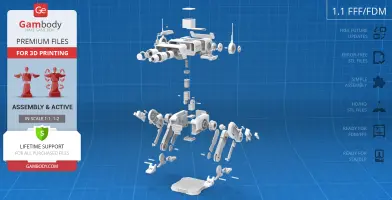
FFF/FDM
Assembly method
not specified
Features
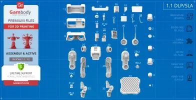
DLP/SLA
Assembly method
not specified
Features
FFF/FDM
Assembly method
not specified
Features
DLP/SLA
Assembly method
not specified
Features
Additional details
Part of diorama
No
Special pack included
No
You will get instant access to the STL files of BD-1 Droid 3D Printing Model | Assembly + Action after completing your purchase. Simply add the model to your cart and check out using PayPal, credit or debit card, Apple Pay, Google Pay, Alipay, or other available payment methods.
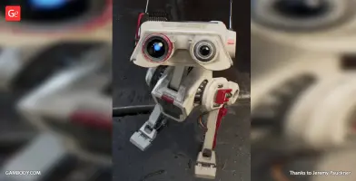
Watch the assembly video for BD-1 Droid 3D Printing Model | Assembly + Action, and explore more tutorials, behind-the-scenes content, 3D printing timelapses, and painting guides on the official Gambody YouTube channel.
This 3D printing design of BD-1 Droid from the Star Wars universe consists of files in StereoLithography (.Stl) format that is optimized for 3D printing.
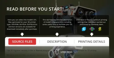
Before printing the files, we strongly recommend reading the PRINTING DETAILS section.
WHAT WILL YOU GET AFTER PURCHASE?
- 4 versions of BD-1 Droid STL files for FFF/FDM and DLP/SLA— files for all versions are available for download after the purchase;
- STL files of high-poly BD-1 Droid model for 3D printing consist of 211 files;
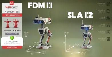
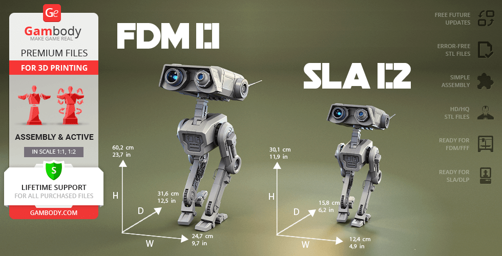
- Sizes for:
- FFF/FDM: 627 mm tall, 268 mm wide, 316 mm deep;
- DLP/SLA: 314 mm tall, 134 mm wide, 156 mm deep;
- Assembly Manual for 1.1 FFF/FDM and 1.1 DLP/SLA versions in PDF and video formats;
- Detailed settings that we provide as a recommendation for Cura, Bambu Studio, Simplify3D, Slic3r and PrusaSlicer for the best print;
- Full technical support from the Gambody Support Team.
Detailed information about these 3D printer STL files is available in the DESCRIPTION section.
Before printing, take a look at Printing Details for recommended settings and tips to achieve better results.
ABOUT THIS 3D MODEL
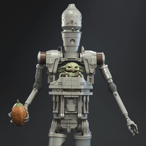
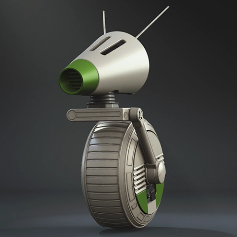
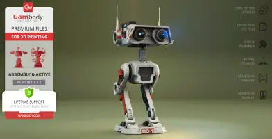
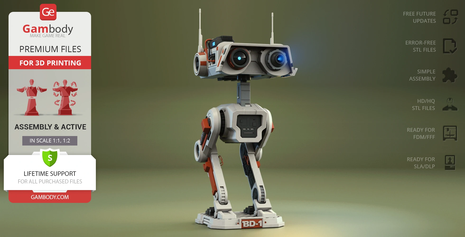
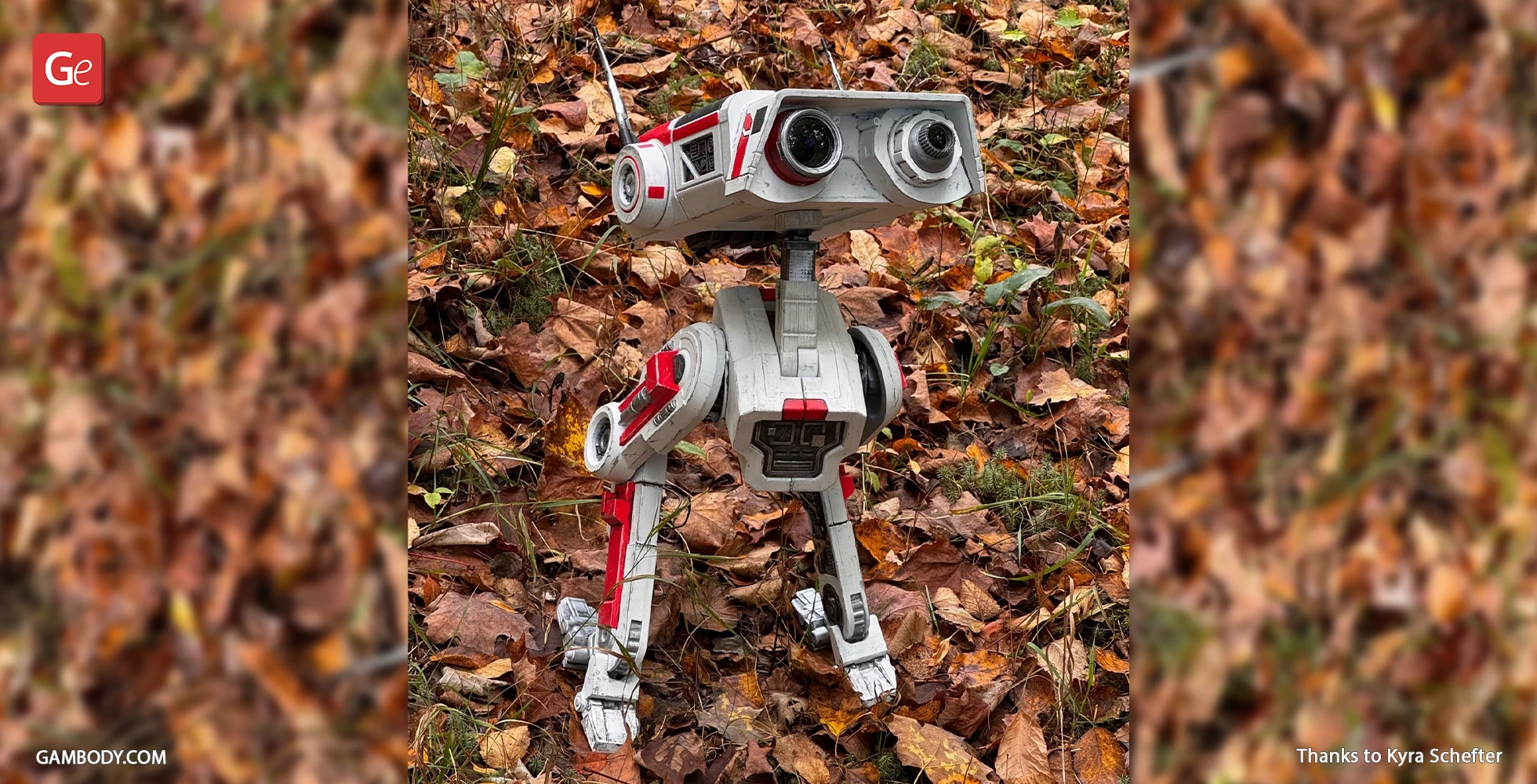
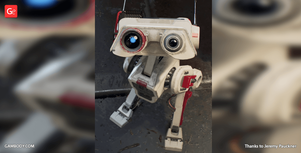
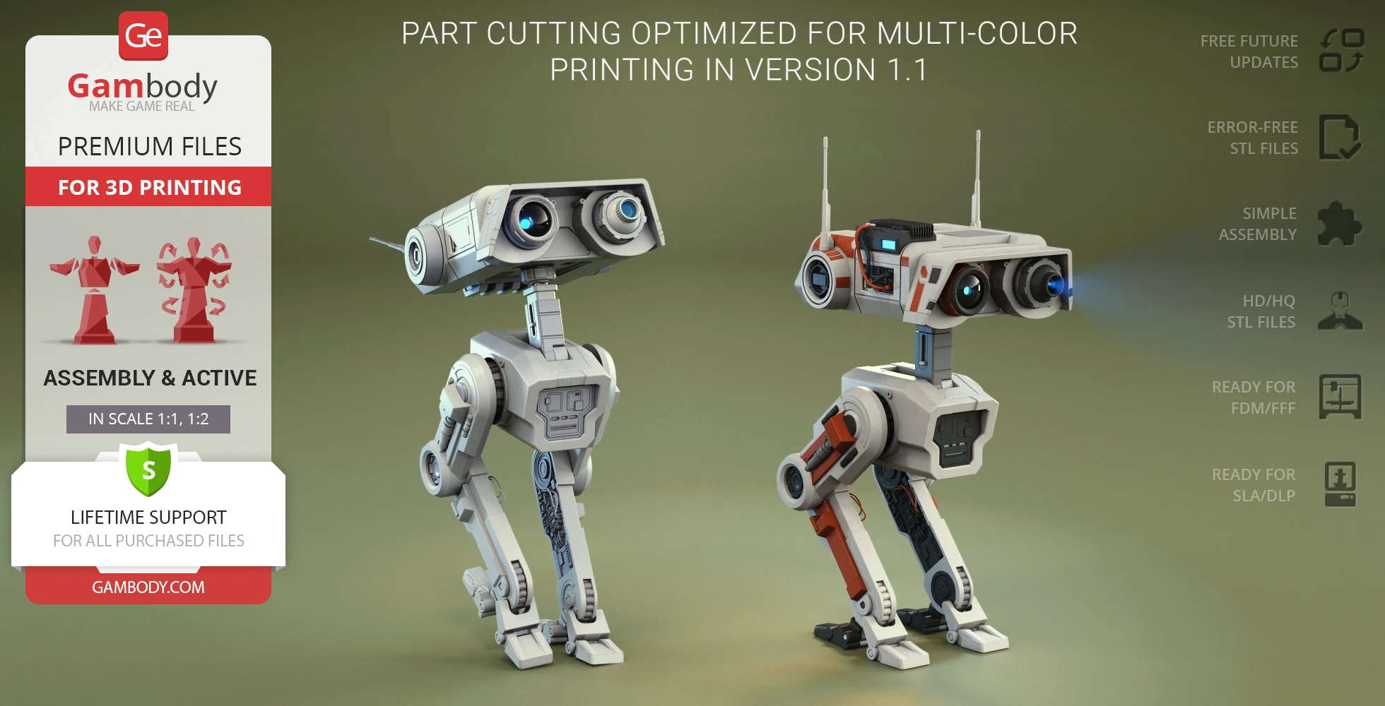
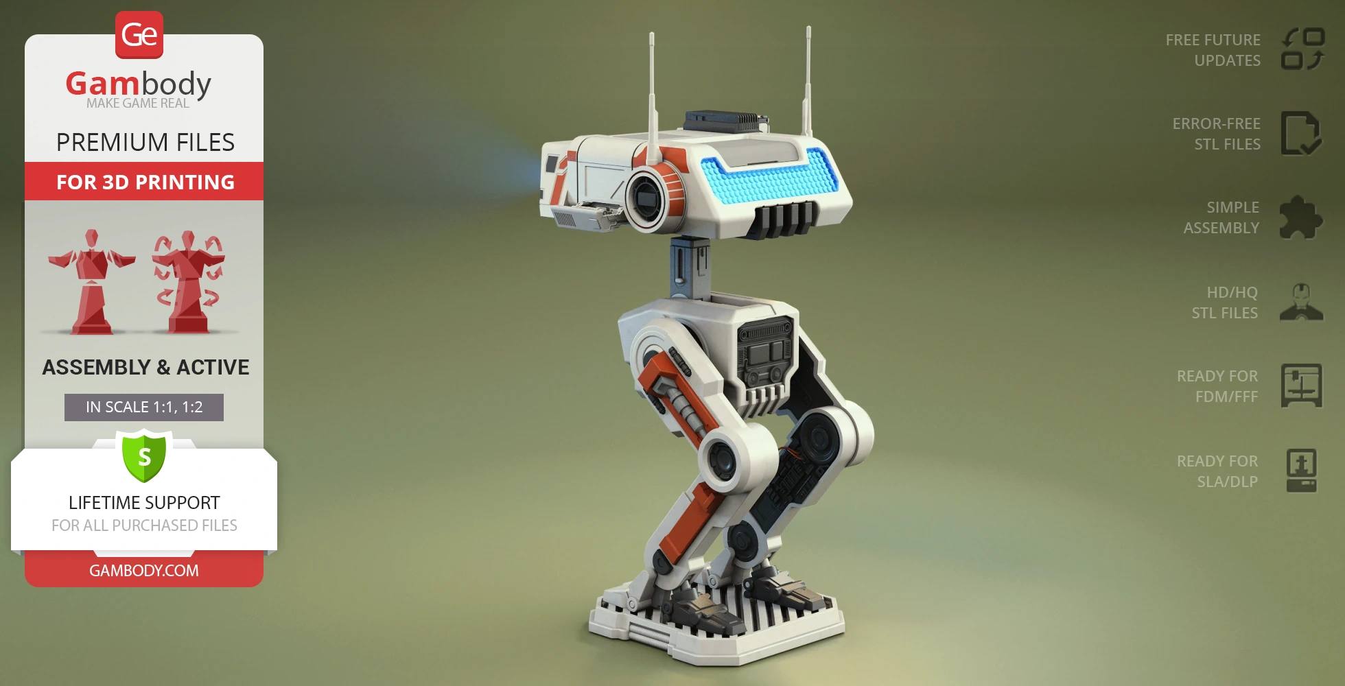
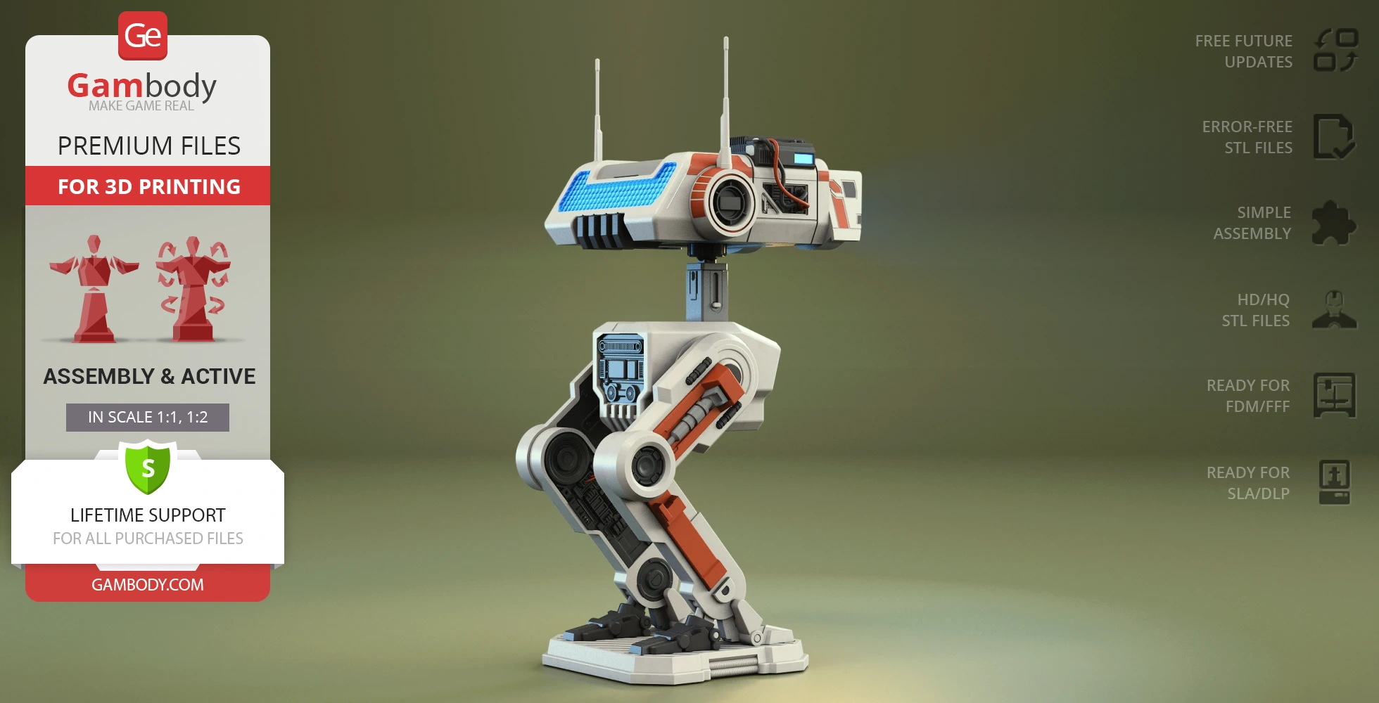
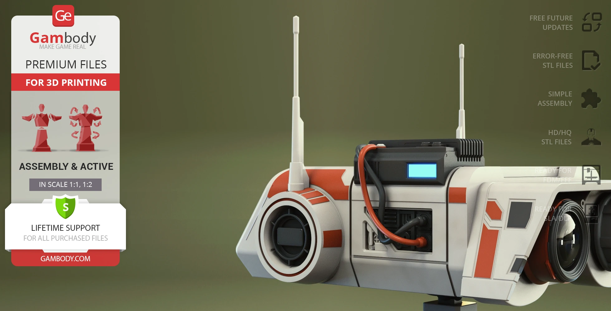
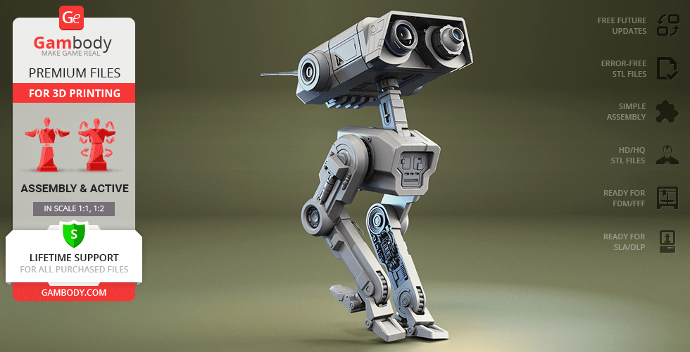
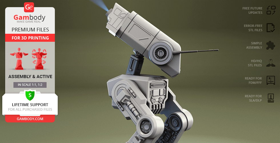
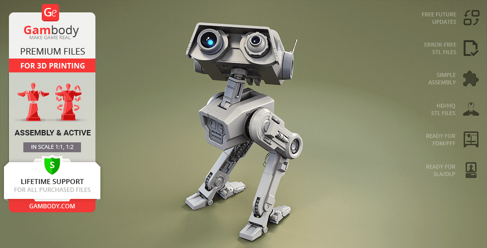
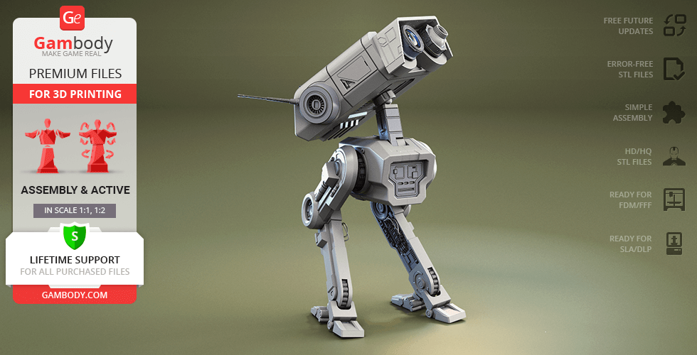
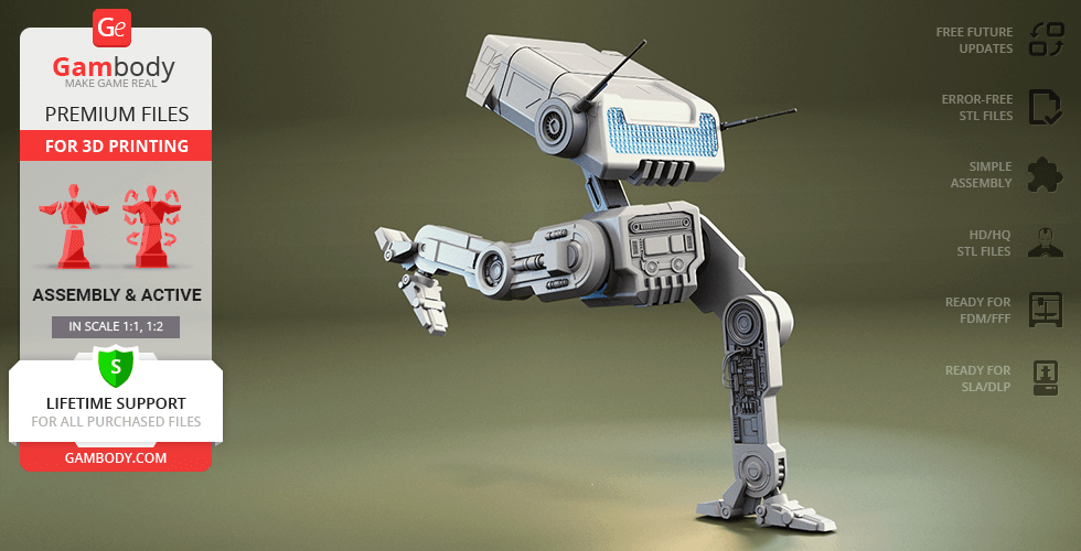
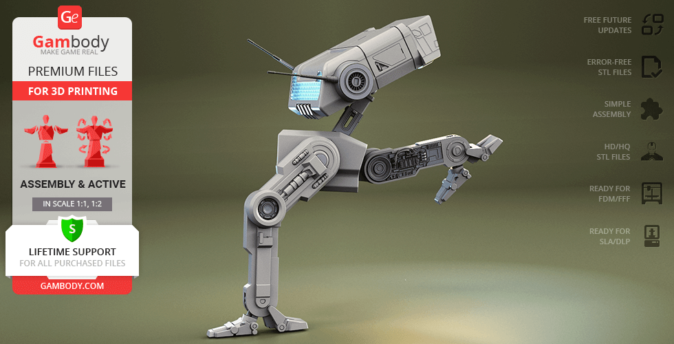
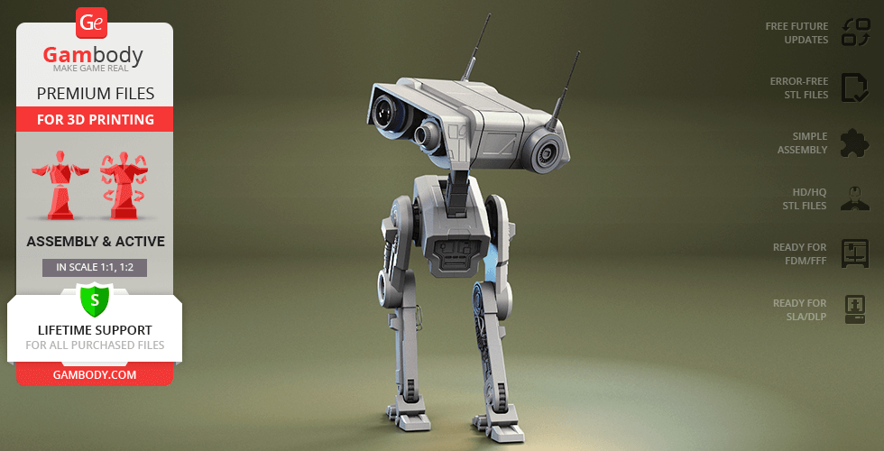
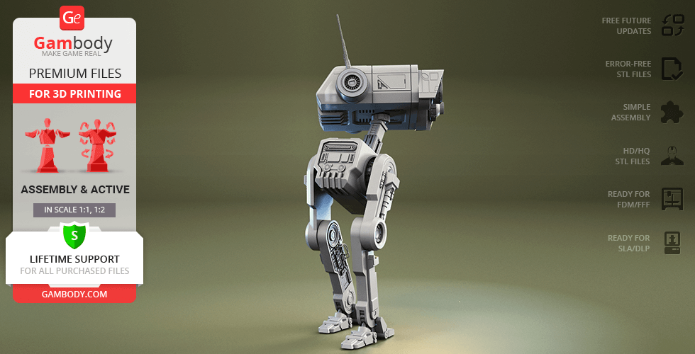
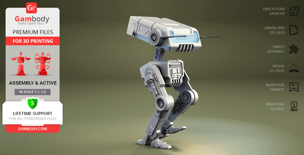
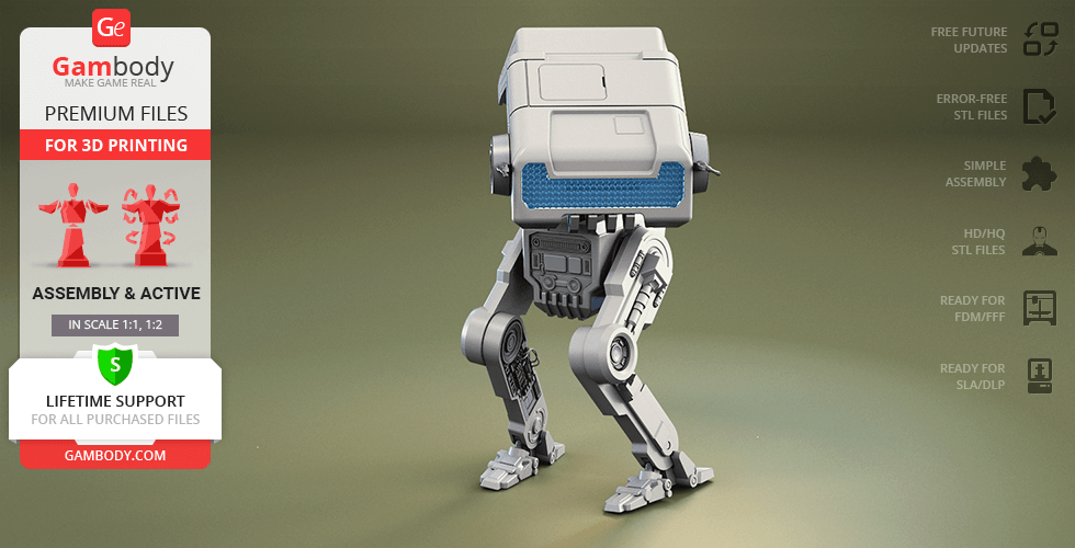
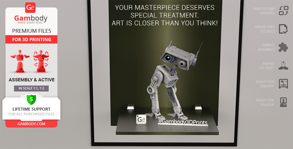
BD-1, the loyal explorer droid from Star Wars Jedi: Fallen Order, showed everyone that even a small companion can make a huge difference in the galaxy. Built to help with archaeology and equipped with a holoprojector, BD-1 accompanied Cal Kestis through old tombs and dangerous ruins. He quickly became a fan favorite with his chirps, scans, and loyal heart, charming audiences again in The Book of Boba Fett. Through his adventures, BD-1 has truly earned his spot among famous Star Wars droids, standing proudly alongside icons like R2-D2, BB-8, the reliable R5-D4, and even agile workers like the Pit Droid.
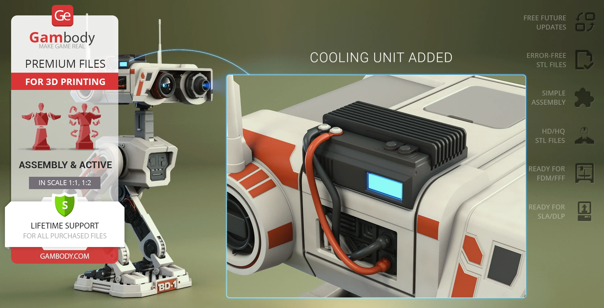
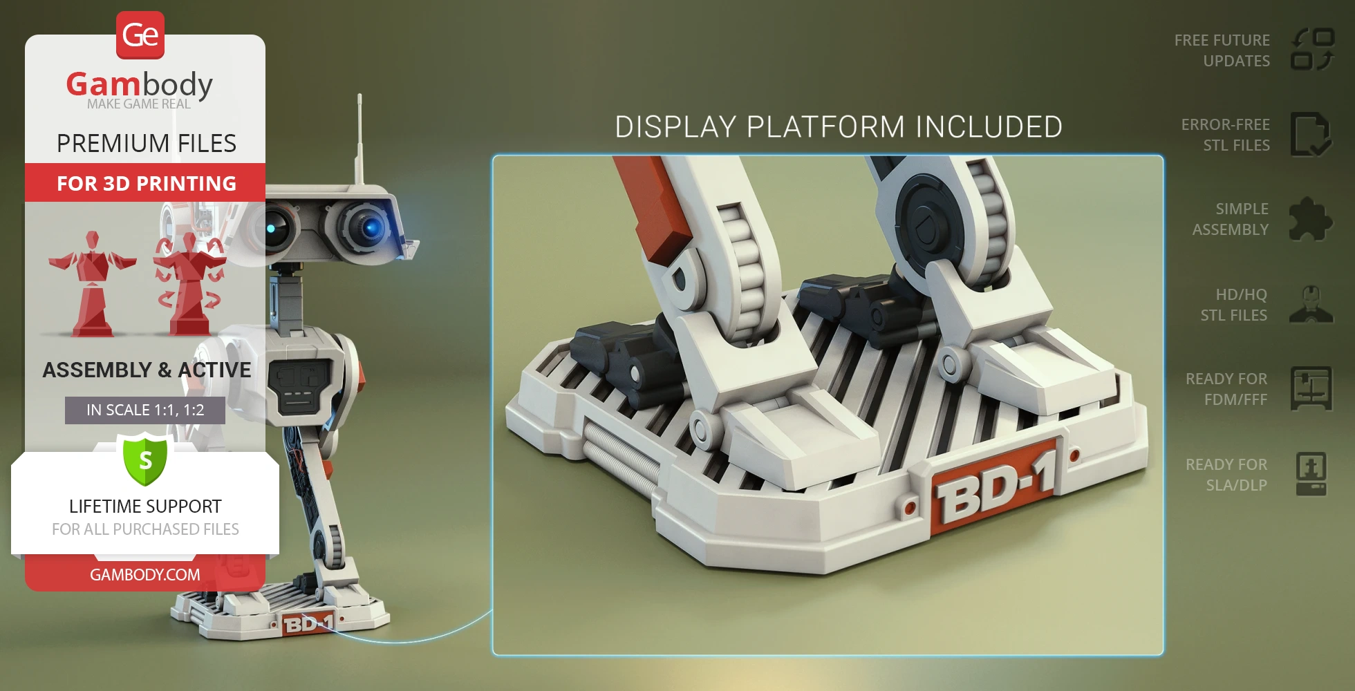
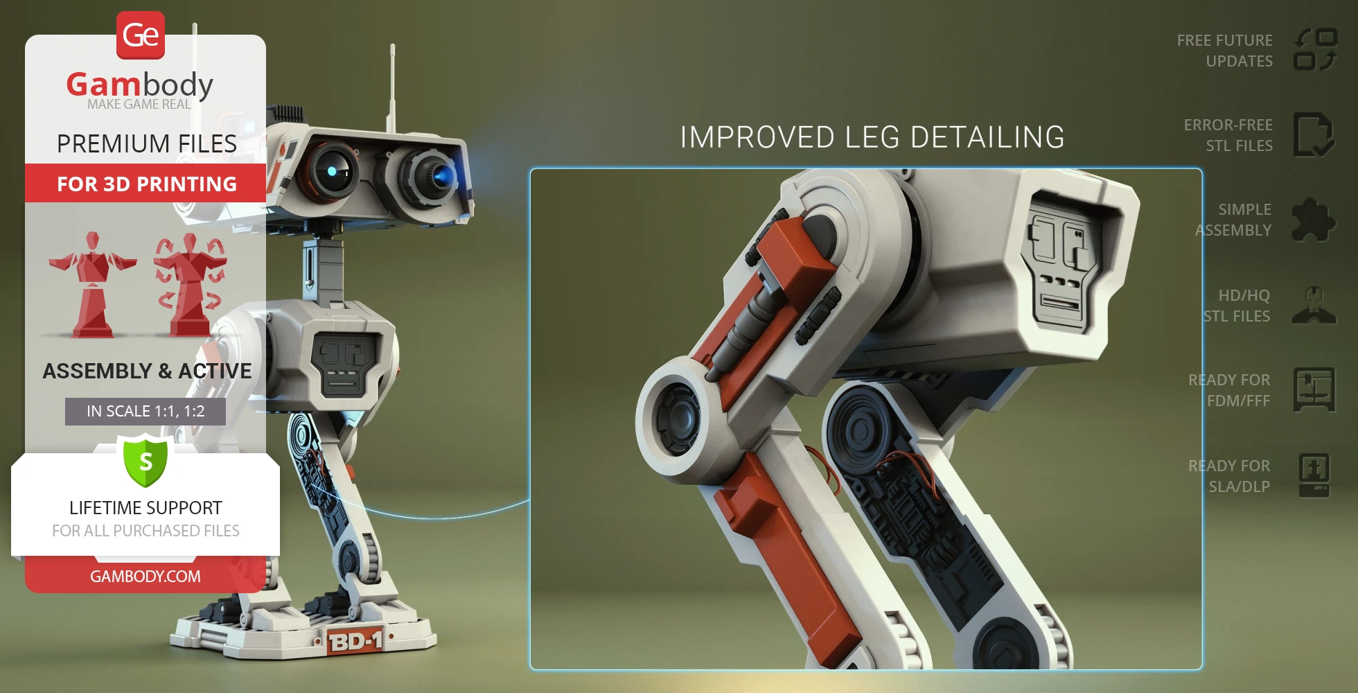
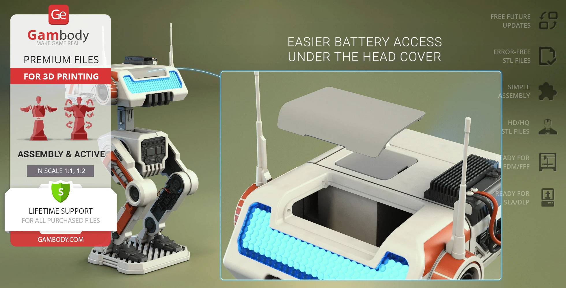
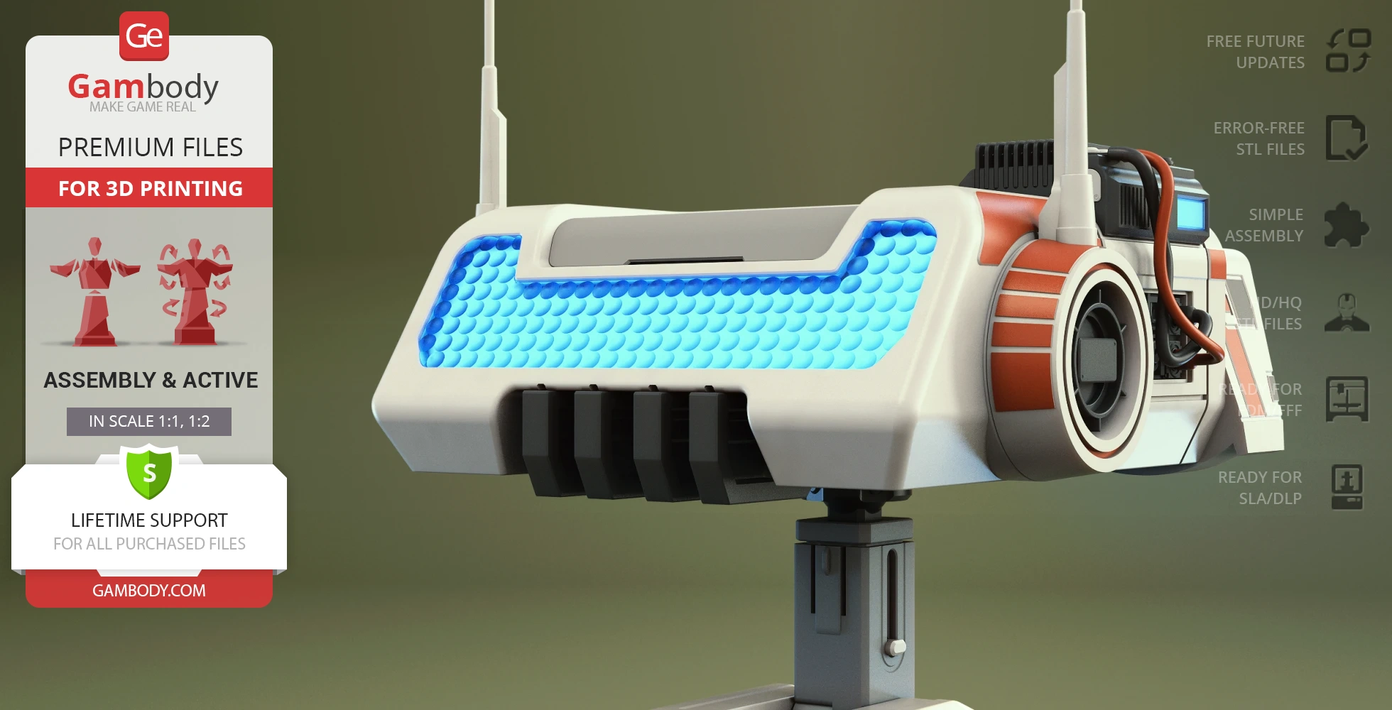
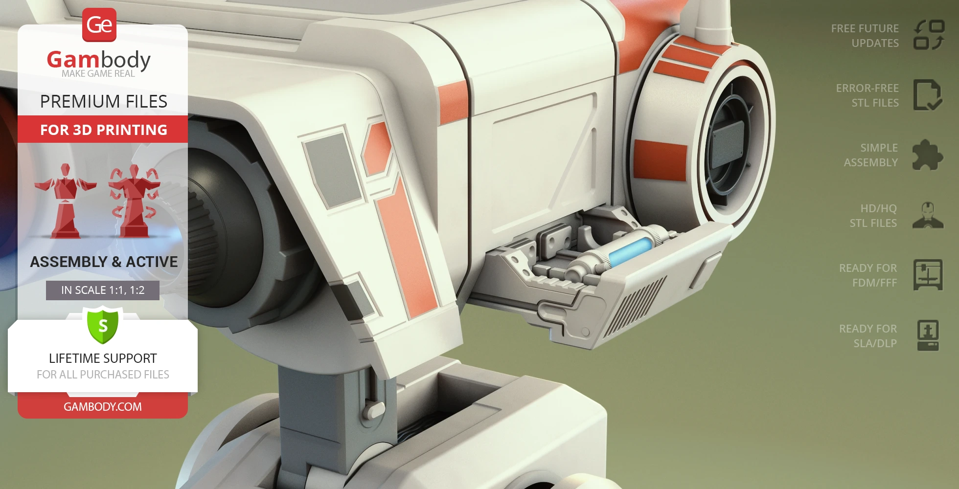
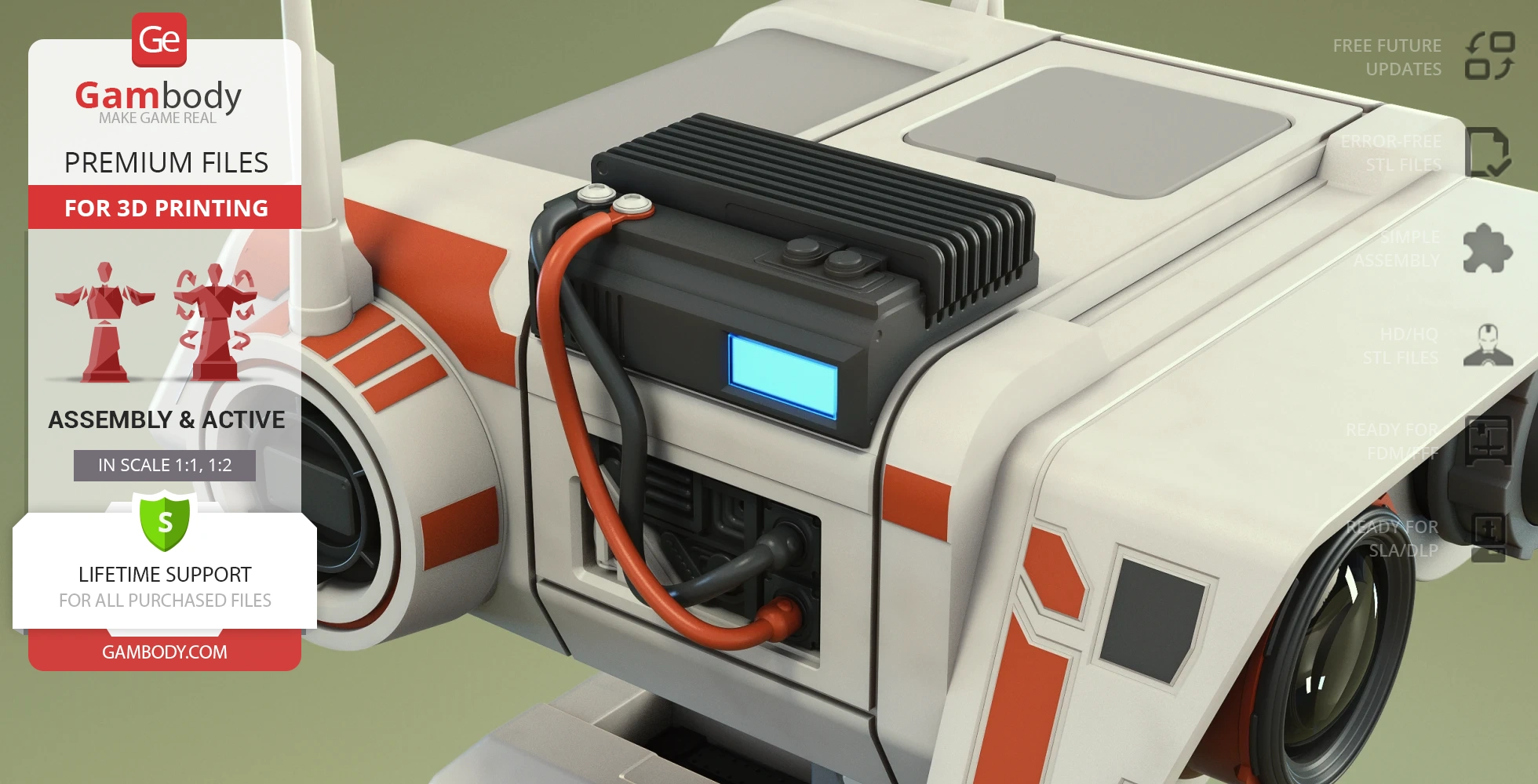
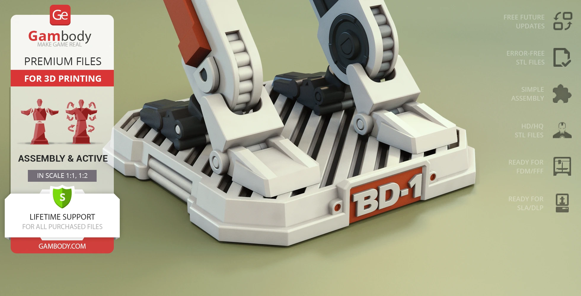
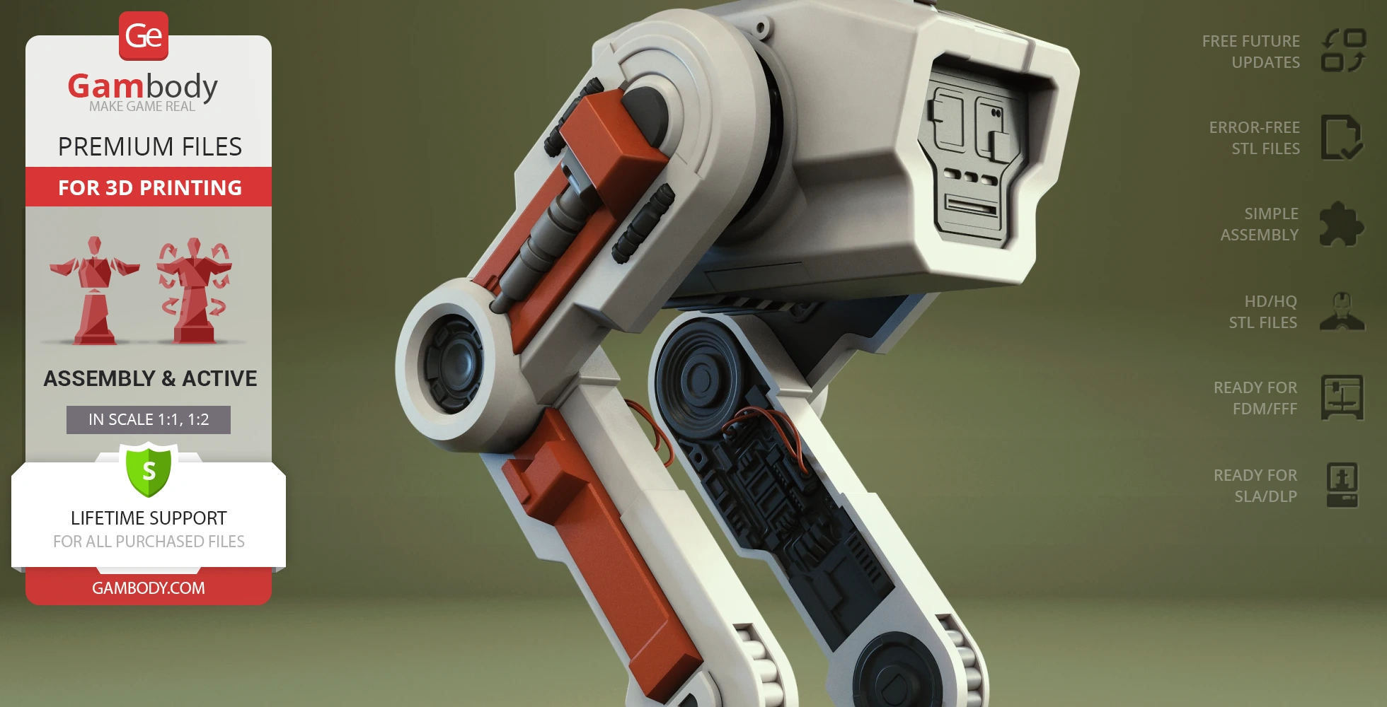
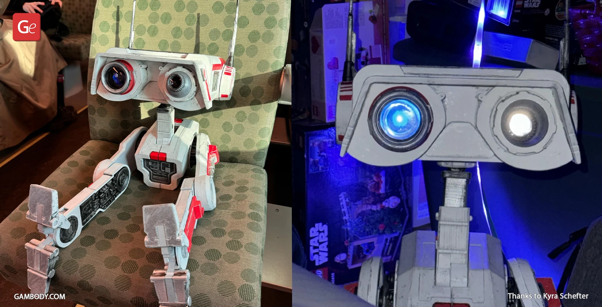
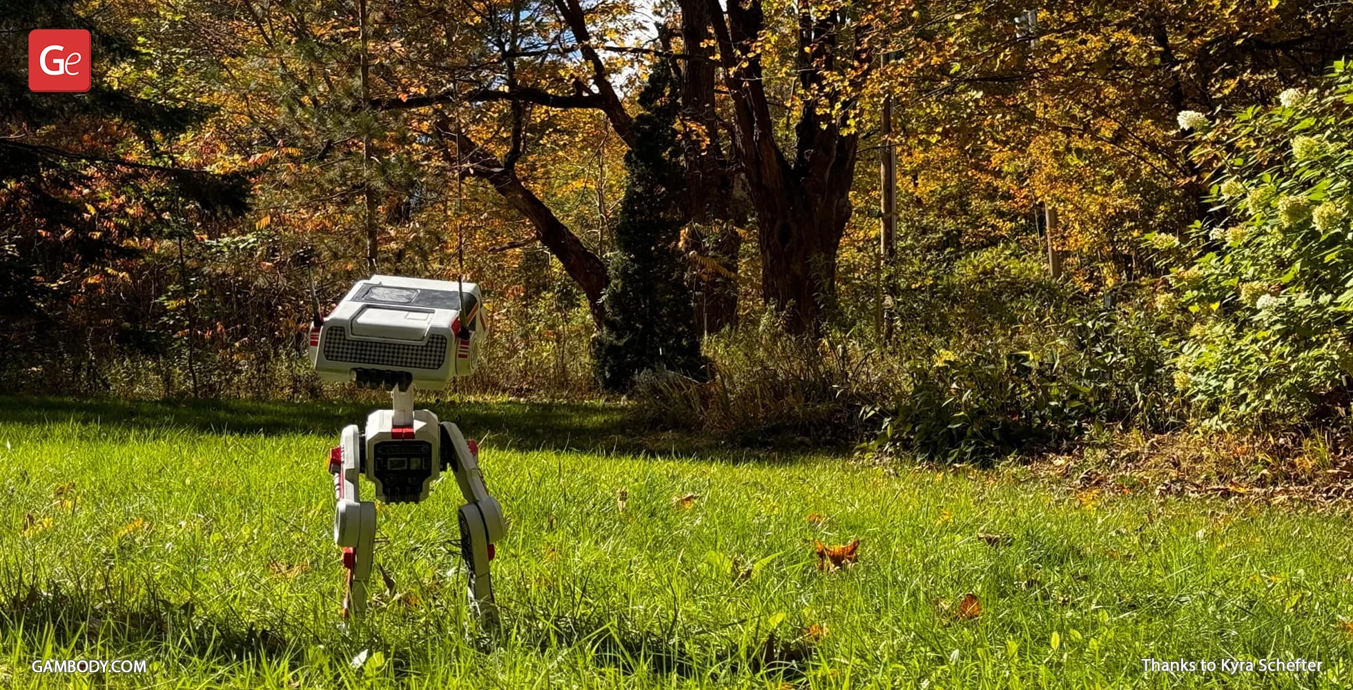
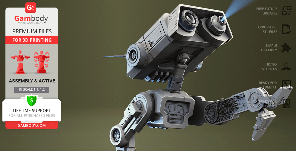
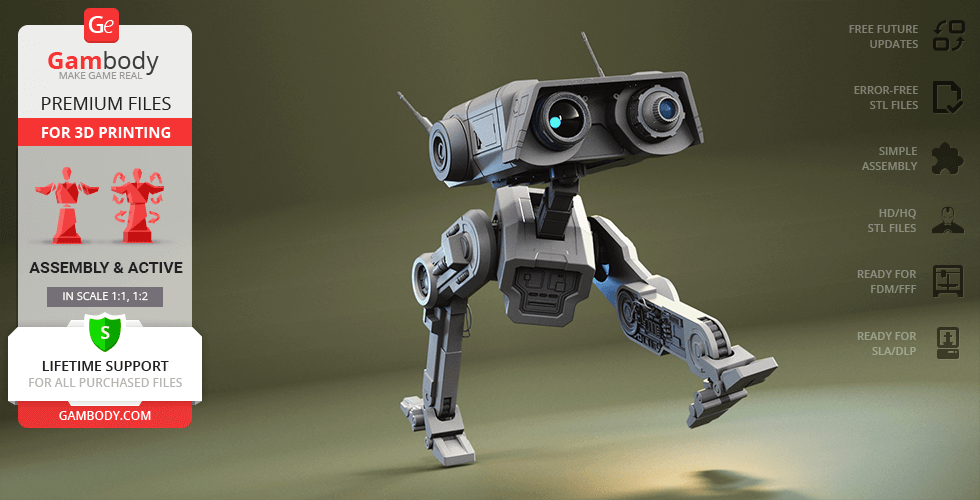
Adapted for flawless 3D printing, this BD-1 model features part cutting optimized for multicolor printing and authentic, screen-accurate details. This 3D print model includes canonical details like ear antennas and internal head components, and a subtle cooling unit. It also features articulated leg joints for improved poseability and a retractable battery compartment with easy access under the head cover for optional LED integration. With a sleek display platform, this BD-1 3D print has everything you need for a standout piece in your collection!
ADAPTATION FOR 3D PRINTING
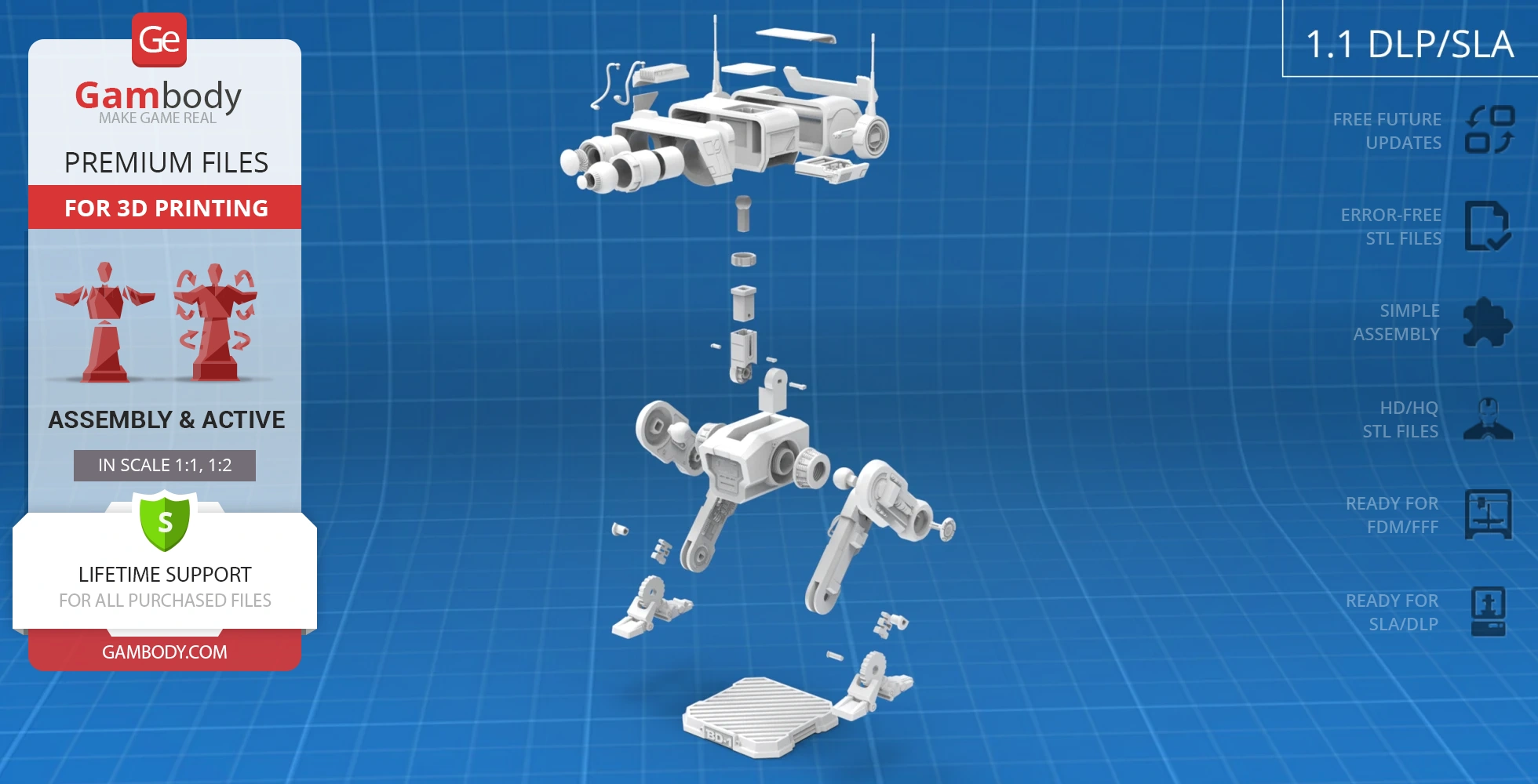
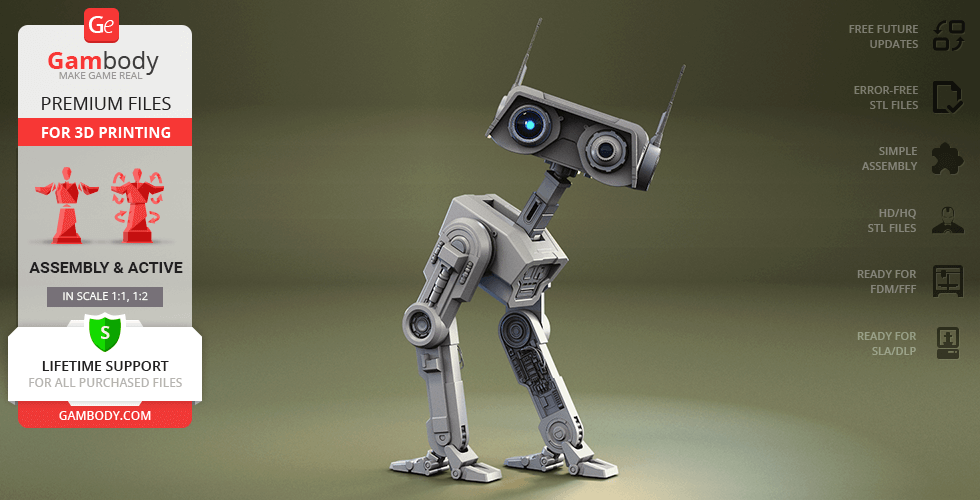
BD-1 Droid 3D printing design is an active assembly model and its moderation and adaptation for different types of 3D printers took the Gambody team 52 hours in total. For you to receive the cleanest 3D printing result possible and to minimize the amount of filament needed for generated support, the BD-1 Droid model was divided into many assembly parts. The model was made fully articulated and equipped with unique active joints that will make your droid companion come alive.
All assembly parts in the 1.0 FFF/FDM and 1.1 FFF/FDM versions are provided in STL files in recommended positions that were worked out in order to ensure the smoothness of the details’ surfaces after printing and that the 3D printing beginners won't face difficulties when placing the parts on a build plate. When downloading any model's file you will also receive "Assembly Manual" for 1.1 FFF/FDM and 1.1 DLP/SLA versions in PDF format. We highly recommend that you get acquainted with the "Assembly video" and "Assembly Manual" before getting down to the BD-01 model.
The 3D printing design is saved in STL files, a format supported by most 3D printers. All STL files for 3D printing have been checked in Netfabb and no errors were shown.
The model's scale was calculated from the approximate height of the droid which is 450 mm. The 3D printing design's chosen scales are 1:1 for the FFF/FDM version and 1:2 for the DLP/SLA version.
VERSIONS' SPECIFICATIONS
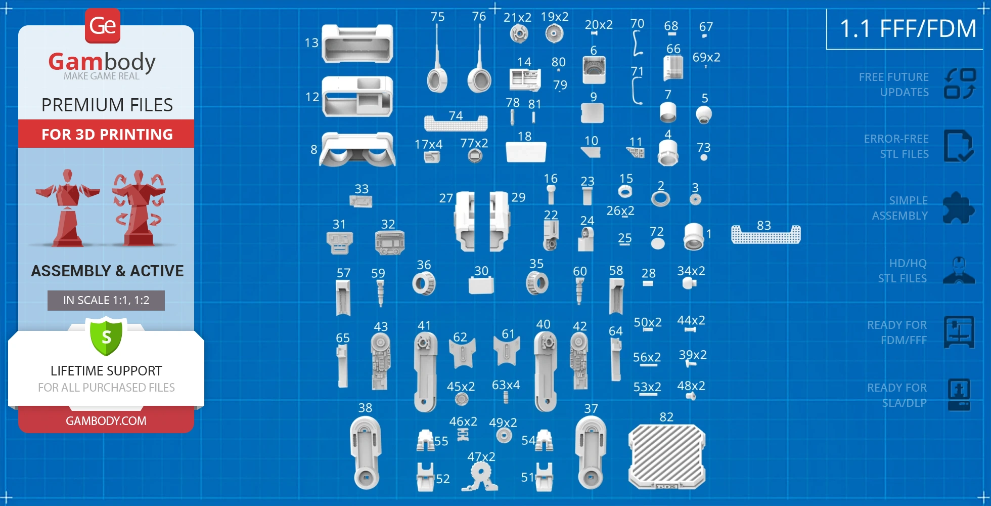
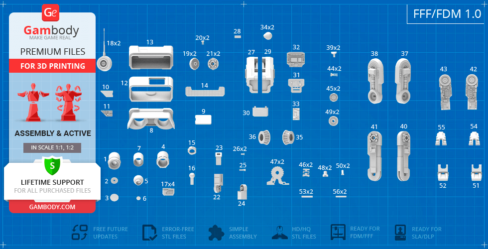
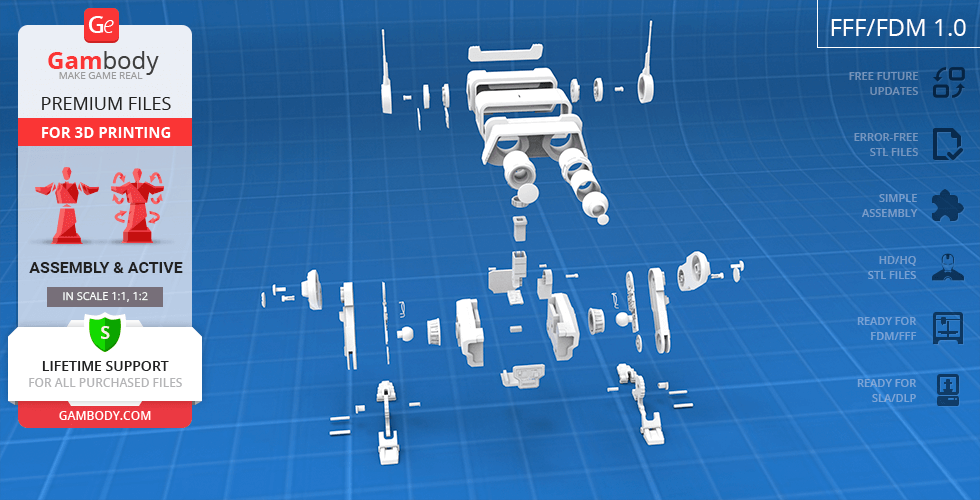
1.1 FFF/FDM version features:
- Contains 82 parts;
- A printed model is 627 mm tall, 268 mm wide, 316 mm deep;
- Improved version of the model;
- Part cutting is potimized for multi-color printing;
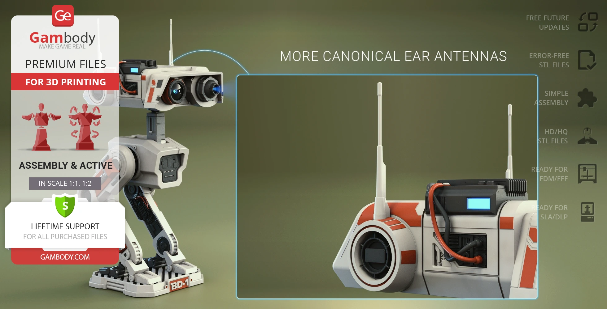
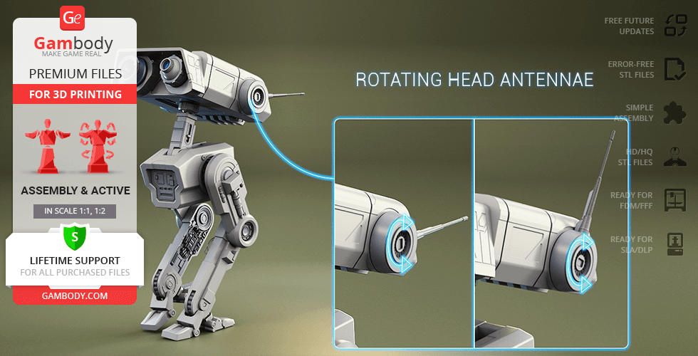
- More canonical ear antennas;
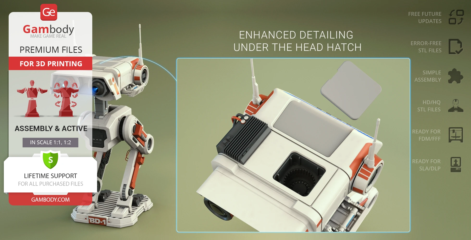
- Enhanced detailing under the head hatch;
- Cool unit added;
- Improved leg detailing;
- Display platform added;
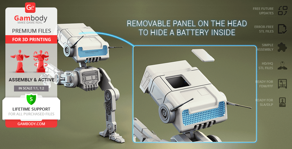
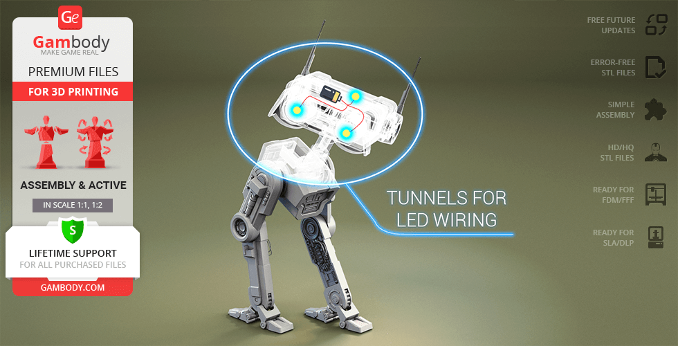
- Tunnels for LED wiring for the sensor, holoprojector, and head lights;removable panelon the head to hide a battery inside;
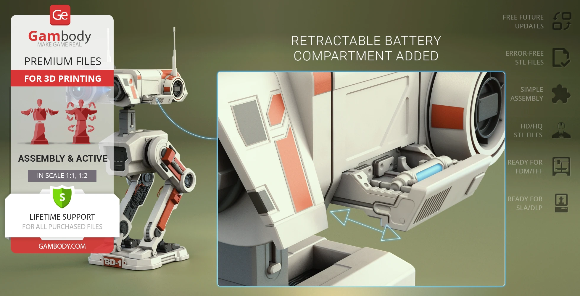
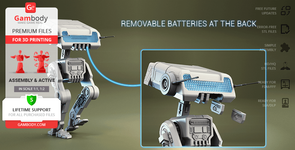
- Retractable battery compartment added;
- Easy battery access under the head cover;
- All parts are divided in such a way that you will print them with the smallest number of support structures.
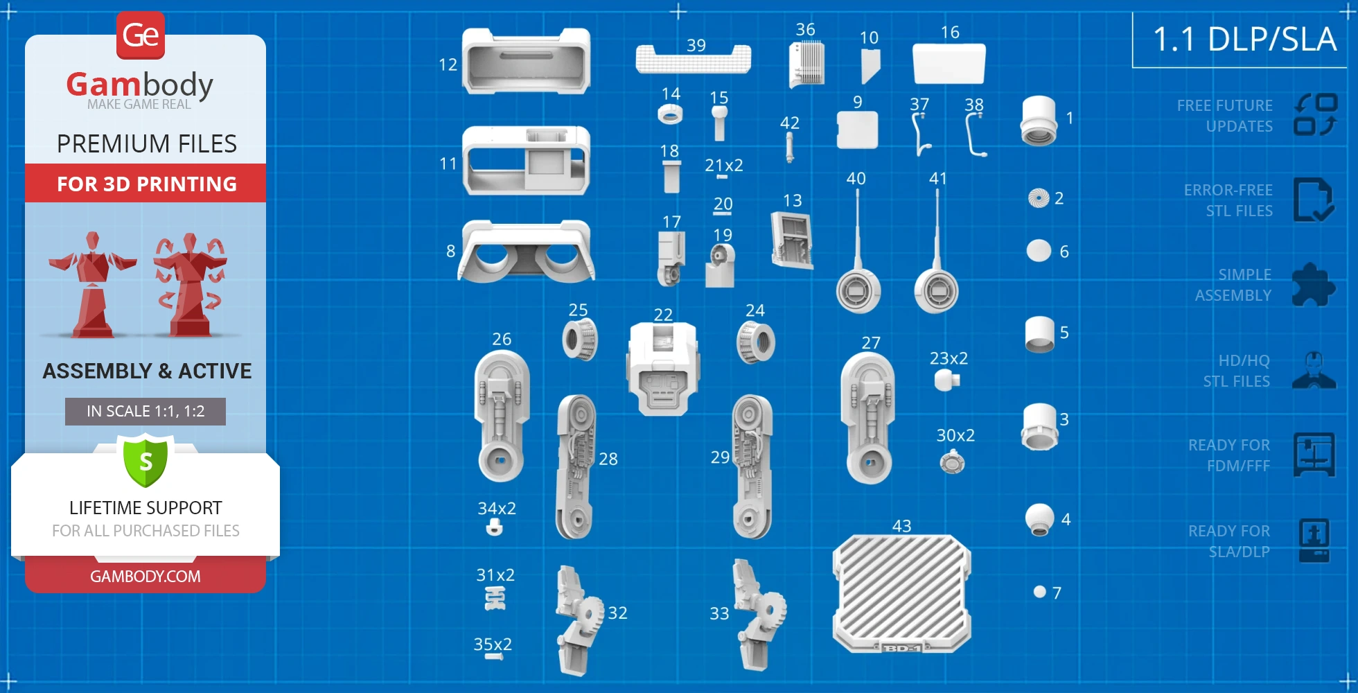
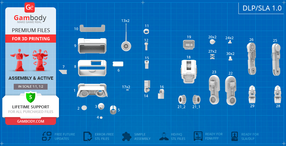
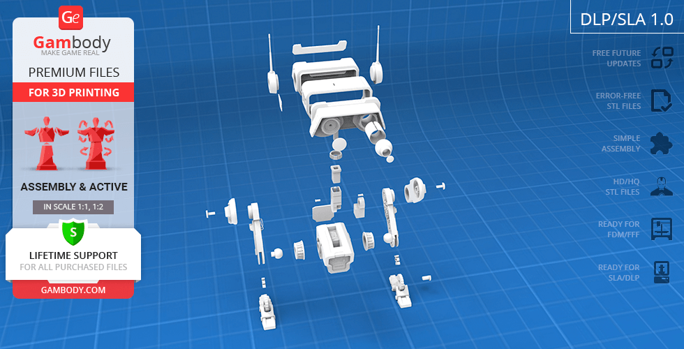
1.1 DLP/SLA version features:
- Contains 43 parts;
- A printed model is 314 mm tall, 134 mm wide, 156 mm deep;
- Improved version of the model;
- More canonical ear antennas;
- Enhanced detailing under the head hatch;
- Cool unit added;
- Improved leg detailing;
- Display platform added;
- Tunnels for LED wiring for the sensor, holoprojector, and head lights;removable panelon the head to hide a battery inside;
- Retractable battery compartment added;
- Easy battery access under the head cover;
- Tunnels for LED wiring for the sensor, holoprojector, and head lights;removable panelon the head to hide a battery inside;
- All parts are divided in such a way to fit the build plates and to ensure that support structures are generated where needed.
1.0 FFF/FDM version features:
- Contains 56 parts;
- A printed model is 602 mm tall, 247 mm wide, 316 mm deep;
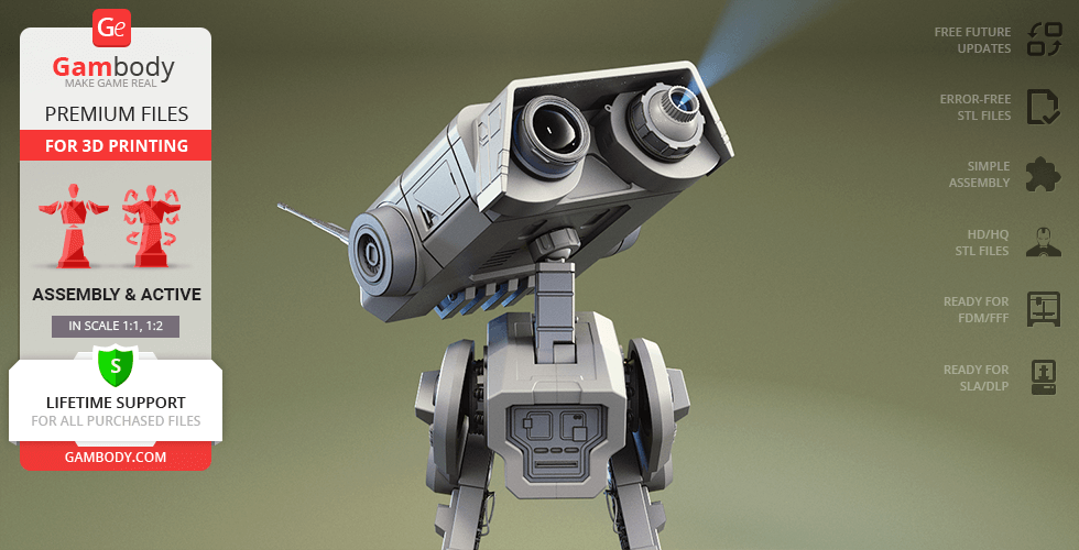
- Right sensor can be assembled with and without the lens;
- Rotating holoprojector;
- Ratchet mechanism allows the articulation of antennae;
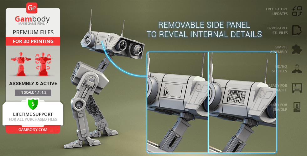
- Removable side panel to reveal internal details;
- The head rotates on a ball joint, the neck can be bentandextended;
- Removable batteries at the back of the head;
- Highly articulated hip and knee joints;
- Springing joint for the articulation of feet;
- The cables for the BD-1 Droid's legs are not provided in the STL files. You may use simple 1.75 mm filament to create the cables;
- Tunnels for LED wiring for the sensor, holoprojector, and head lights;removable panelon the head to hide a battery inside;
- All parts are divided in such a way that you will print them with the smallest number of support structures.
1.0 DLP/SLA version features:
- Contains 30 parts;
- A printed model is 301 mm tall, 124 mm wide, 158 mm deep;
- Right sensor can be assembled with and without the lens;
- Rotating holoprojector;
- Ratchet mechanism allows the articulation of antennae;
- Removable side panel to reveal internal details;
- The head rotates on a ball joint, the neck can be bentandextended;
- Removable batteries at the back of the head;
- Highly articulated hip and knee joints;
- Springing joint for the articulation of feet;
- The cables for the BD-1 Droid's legs are not provided in the STL files. You may use simple 1.75 mm filament to create the cables;
- Tunnels for LED wiring for the sensor, holoprojector, and head lights;removable panelon the head to hide a battery inside;
- All parts are divided in such a way to fit the build plates and to ensure that support structures are generated where needed.
You can get the STL Files of BD-1 Droid 3D Print Model immediately after the purchase! Just click the green Buy button in the top-right corner of the model’s page. You can pay with PayPal or your credit card.
Watch the tutorial on how to assemble the 3D Printed BD-1 Droid Model from the provided 3D Print Files at Gambody YouTube channel.
Also, you may like more Star Wars STL Files, as well as other Droids3D Print Models.
_______
FAQ:
Average customer rating (20 reviews)
4
Ratings breakdown
Click a star rating to filter reviews
Overall experience
Level of detail in the model
4
Model cut quality and assembly guide
4
Clarity and accuracy of the model page
4
Level of detail in the model
4
Model cut quality and assembly guide
3.8
Clarity and accuracy of the model page
4.6
This type of fitting issue can occur if the model was printed in a scale or version that differs from the recommended one — for example, using the DLP/SLA version on an FDM printer. Each version on the model page is prepared in its own optimized scale, with cuts and tolerances tailored specifically for the intended printing technology. Using the resin-optimized version on a filament printer or downscaling the model may lead to reduced detail, shrinkage, or loose joints. In such cases, we unfortunately cannot guarantee proper fit or stability.
For your current print, you may try placing a small piece of note paper inside the joint to tighten the connection and help balance the head more securely.
If you have any further questions or images to share about your BD-1 3D print or need additional assistance, feel free to reach out — we’re always happy to help!
Level of detail in the model
0.4
Model cut quality and assembly guide
0.3
Clarity and accuracy of the model page
1
But there is the 1.1 Minor Modification version of the droid, which includes more canonical ear antennas, enhanced detailing under the head hatch, a cool unit, improved leg detailing, and a display platform. There are 83 files in this version for FFF/FDM 3D printers.
To access these upgraded files, please select the latest version from the dropdown menu under the Source Files tab, as shown in the image below.
We truly hope you’ll give the model a second chance with the improved files. We also understand that your current rating may reflect unclear download instructions, and we’ll take that into account to make the process clearer for all users.
Level of detail in the model
1
Model cut quality and assembly guide
1
Clarity and accuracy of the model page
1
Level of detail in the model
5
Model cut quality and assembly guide
5
Clarity and accuracy of the model page
5
Level of detail in the model
5
Model cut quality and assembly guide
5
Clarity and accuracy of the model page
5
Level of detail in the model
5
Model cut quality and assembly guide
5
Clarity and accuracy of the model page
5
Level of detail in the model
5
Model cut quality and assembly guide
5
Clarity and accuracy of the model page
5
Level of detail in the model
5
Model cut quality and assembly guide
5
Clarity and accuracy of the model page
5
Level of detail in the model
5
Model cut quality and assembly guide
5
Clarity and accuracy of the model page
5
Level of detail in the model
5
Model cut quality and assembly guide
5
Clarity and accuracy of the model page
5
Level of detail in the model
5
Model cut quality and assembly guide
5
Clarity and accuracy of the model page
5
Level of detail in the model
2
Model cut quality and assembly guide
2
Clarity and accuracy of the model page
2
Level of detail in the model
4
Model cut quality and assembly guide
4
Clarity and accuracy of the model page
4
Level of detail in the model
3
Model cut quality and assembly guide
3
Clarity and accuracy of the model page
3
Level of detail in the model
5
Model cut quality and assembly guide
5
Clarity and accuracy of the model page
5
Level of detail in the model
4
Model cut quality and assembly guide
4
Clarity and accuracy of the model page
4
Level of detail in the model
5
Model cut quality and assembly guide
5
Clarity and accuracy of the model page
5
Level of detail in the model
1
Model cut quality and assembly guide
1
Clarity and accuracy of the model page
1
Level of detail in the model
5
Model cut quality and assembly guide
5
Clarity and accuracy of the model page
5
Level of detail in the model
5
Model cut quality and assembly guide
5
Clarity and accuracy of the model page
5
Below you'll find detailed slicing settings for Bambu Studio 2.0+, Orca Slicer 2.0+, UltiMaker Cura 5.0+, PrusaSlicer 2.0+, Slic3r 1.3+, Simplify3D 5.0+ to help you get the best results when printing this model. These settings are optimized specifically for this 3D model, but please note they may need slight adjustments depending on your printer or filament. When in doubt, refer to your printer's user manual.
To avoid printing issues and achieve the best quality, we highly recommend applying the following settings:
For better quality use 0.12 mm layer height, for fast printing use 0.2 mm layer height. For pins and the Ge connectors, use 0.2 layer height.
120-150% of your Layer Height
But you can paint the seam if you want.
You have to calibrate this parameter
You have to calibrate this parameter
You have to calibrate this parameter
For pins and power elements of the structure, such as the vehicle frame, use 3 loop
Disabled for vehicles and enabled for characters
For 0,2 Layer Height
The parameters in this tab vary greatly, it all depends on the quality of your printer. For example, if you have a classic Ender3, stick to the minimum parameters, but if you have a newer printer, for example Anycubic cobra 3 v2, you can select the maximum recommended values
Settings for advanced users, change these parameters only if you have sufficient 3D printing expertise
Enable this parameter if your model requires supports
We also recommend placing and removing supports manually in some places using special button
1-2 loops for more thick support
Top Z distance = 1-1.3 layer Height. If the supports are hard to remove, try increasing this setting by 0.1-0,4 mm
Bottom Z distance = 1-1.3 layer Height. If the supports are hard to remove, try increasing this setting by 0.1-0,4 mm
You have to calibrate this parameter which one is better for your filament
Increase this parameter if the supports are hard to remove from walls
For PLA and PETG filament types
5-8 mm is optional for small prints that have bad adhesion to the build plate
You have to calibrate this parameter
Read the description on your filament roll
Read the description on your filament roll and increase this parameter for fast printers
Read the description on your filament roll and increase this parameter for fast printers
For better quality use 0.12 mm layer height, for fast printing use 0.2 mm layer height. For pins and the Ge connectors, use 0.2 layer height.
120-150% of your Layer Height
But you can paint the seam if you want.
0.01-0.05 You have to calibrate this parameter
0.01-0.05 You have to calibrate this parameter
0.1-0.2 You have to calibrate this parameter
For pins and power elements of the structure, such as the vehicle frame, use 3 loop
Disabled for vehicles and ships, enabled for characters
For 0,2 Layer Height
For 0,2 Layer Height
The parameters in this tab vary greatly, it all depends on the quality of your printer. For example, if you have a classic Ender3, stick to the minimum parameters, but if you have a newer printer, for example, Anycubic Kobra 3 Or Bambulab A1, you can select the maximum recommended values.
Settings for advanced users, change these parameters only if you have sufficient 3D printing expertise
Enable this parameter if your model requires supports
We also recommend placing and removing supports manually in some places using special button
Top Z distance = 1-1.3 layer Height. If the supports are hard to remove, try increasing this setting by 0.1-0,4 mm
Bottom Z distance = 1-1.3 layer Height. If the supports are hard to remove, try increasing this setting by 0.1-0,4 mm
Increase this parameter if the supports are hard to remove from walls
For PLA and PETG filament types
5-8 mm is optional for small prints that have bad adhesion to the build plate
Read the description on your filament roll
Read the description on your filament roll and increase this parameter for fast printers
You have to calibrate this parameter
Read the description on your filament roll and increase this parameter for fast printers
Read the description on your filament roll
This field is filled in according to your printer specifications when you add it to the slicer.
You can add custom G-code here for the start and end of the print. However, be careful - this is for advanced users only!
You have to calibrate your printer using Ge retraction test models
Retraction Length: For direct-drive setups use 0.5 mm to 2.5 mm; for Bowden extruders use 5 to 7 mm
This is how fast the filament is pulled back—40-60 mm/s for direct drive and 30-50 mm/s for Bowden setups.
You have to calibrate this parameter: Reduce it until the printer starts to hit the parts with the nozzle during printing, then increase it by 0.2.
For better quality use 0.12 mm layer height, for fast printing use 0.2 mm layer height. For pins and the Ge connectors, use 0.2 layer height.
120-150% of your Layer Height
To increase the strength of the print parts, use wall line count: 3
For pins and connectors use 50% Infill
These parameters are for standard PLA plastic. If you are using a different type of plastic, check the printing temperature recommended by the manufacturer. Also, read the description on your filament spool. For fast printers, add +30 °C to the current parameters.
The parameters in this tab vary greatly, it all depends on the quality of your printer. For example, if you have a classic Ender3, stick to the minimum parameters, but if you have a newer printer, for example Anycubic cobra 3 v3, you can select the maximum recommended values
Settings for advanced users, change these parameters only if you have sufficient 3D printing expertise.
You need to calibrate this parameter using Gambody test models. These values are average values for a Direct Drive extruder; for a Bowden extruder, the values should be increased.
You need to calibrate this parameter using Gambody test models. These values are average values for a Direct Drive extruder; for a Bowden extruder, the values should be increased.
Use this value other than 0 if your nozzle catches on the internal infill during travel moves. Try to keep this value as low as possible in height.
Use normal supports to support large, straight surfaces (most mechanical or technical parts).
You have to calibrate this parameter according to the capabilities of your printer and your filament, using a Gambody test models.
Use 1 instead of 0 if your supports are thin and tall. They will be harder to remove, but much stronger.
Top Z distance = 1-1.3 layer Height. If the supports are hard to remove, try increasing this setting by 0.1-0,4 mm
Increase this parameter if the supports are hard to remove from walls
Use tree supports to support complex objects, such as characters.
You have to calibrate this parameter according to the capabilities of your printer and your filament, using a Gambody test models.
Top Z distance = 1-1.3 layer Height. If the supports are hard to remove, try increasing this setting by 0.1-0,4 mm
Increase this parameter if the supports are hard to remove from walls
Use a skirt for all parts when printing on outdated printers.
Use a brim when printing thin but tall parts, as well as parts with a small bed adhesion area.
For better quality use 0.12 mm layer height, for fast printing use 0.2 mm layer height. For pins and the Ge connectors, use 0.2 layer height.
120-150% of your Layer Height
for 0.2 Layer Height
But you can paint the seam if you want.
(for PLA and PETG)
(5-8 mm is optional for small prints that have bad adhesion to the build plate)
Enable this parameter if your model requires supports
(45-50 degree)You have to calibrate this parameter according to the capabilities of your printer
and your filament, using a Gambody test models.
Top contact Z distance = 1-1.3 layer Height. If the supports are hard to remove, try
increasing this setting by 0.1-0,4 mm
Top contact Z distance = 1-1.3 layer Height. If the supports are hard to remove, try
increasing this setting by 0.1-0,4 mm
Increase this parameter if the supports are hard to remove from walls
The parameters in this tab vary greatly, it all depends on the quality of your printer. For example, if you have a classic Ender3, stick to the minimum parameters, but if you have a newer printer, for example Anycubic cobra 3 v3, you can select the maximum recommended values
Settings for advanced users, change these parameters only if you have sufficient 3D printing expertise. Use the minimum value for outdated printers without acceleration calibration, and the maximum value for modern printers if you need it.
These settings only work for 3D printers with multiple extruders
You can try setting all parameters in this section, except the First layer, to values between 0.75% of your nozzle diameter and 1.25% of your nozzle diameter. Adjusting them will help you work out the optimal parameters for the best quality for your print. As for the First layer, you can set it to 150% of the diameter of your nozzle for better adhesion to the build plate (for a nozzle with a diameter of 0.4 mm, the First layer extrusion width can be from 0.3 mm to 0.5 mm)
For better printing quality you have to calibrate this parameter using Gambody test model.
Check your filament manufacturer's temperature recommendations on the spool.
Cooling parameters depends on the material you use for printing.
*for PLA
For better quality use 0.12 mm layer height, for fast printing use 0.2 mm layer height. For pins and the Ge connectors, use 0.2 layer height.
120-150% of your Layer Height
For 0.12 Layer Height
For 0.12 Layer Height
For pins and connectors use 50% Infill
Use skirt for outdated 3d printers
(5-8 mm is optional for small prints that have bad adhesion to the build plate)
Enable this parameter if your model requires supports
(45-60 degree)You have to calibrate this parameter according to the capabilities of your printer and your filament, using a Gambody test models
Contact Z distance = 1-1.3 layer Height. If the supports are hard to remove, try increasing this setting by 0.1-0,4 mm
The parameters in this tab vary greatly, it all depends on the quality of your printer. For example, if you have a classic Ender3, stick to the minimum parameters, but if you have a newer printer, for example Anycubic cobra 3 v3, you can select the maximum recommended values
Settings for advanced users, change these parameters only if you have sufficient 3D printing expertise. Use the minimum value for outdated printers without acceleration calibration, and the maximum value for modern printers if you need it.
You have to calibrate this parameter from 0.9 to 1.1 according to the capabilities of your printer and your filament, using a Gambody test models.
Check your filament manufacturer's temperature recommendations on the spool.
Cooling parameters depends on the material you use for printing.
Calibrate this value if you need to reduce or improve the adhesion between the plastic and the heat bed
Your current nozzle diameter
You need to calibrate this parameter using Gambody test models. These values are average values for a Direct Drive extruder; for a Bowden extruder, the values should be increased.
Your current nozzle diameter
You have to calibrate this parameter using Gambody test models.
You need to calibrate this parameter using Gambody test models. These values are average values for a Direct Drive extruder; for a Bowden extruder, the values should be increased.
For better quality use 0.12 mm layer height, for fast printing use 0.2 mm layer height. For pins and the Ge connectors, use 0.2 layer height.
For 0,2 Layer Height
For 0,2 Layer Height
To increase the strength of the print parts, use Outline Perimeters: 3
You can enable this parameter to print rounded or spherical models, as well as character models.
Use this option only if your parts are too tight. but better calibrate your printer extrusion
Use this option only if your parts are too tight. but better calibrate your printer extrusion
Use 2 and more if you want to create skirt instead brim
1-2 for skirt and 10-20 for brim
Use for wipe nozzle if you need
Use For ABS filament
For pins and connectors use 50% Infill
Top Z distance = 1-1.3 layer Height. If the supports are hard to remove, try increasing this setting by 0.1-0,4 mm
Calibrate your filament and detect optimal temperature for it
Average temperature for PLA filament
The parameters in this tab vary greatly, it all depends on the quality of your printer. For example, if you have a classic Ender3, stick to the minimum parameters, but if you have a newer printer, for example Anycubic cobra 3 v3, you can select the maximum recommended values
Settings for advanced users, change these parameters only if you have sufficient 3D printing expertise.