


Files
3D model format
Stereolithography (.stl)
Total files
Slicer settings
Mesh error check
Netfabb
Support
Lifetime support from Gambody team
Update requests
Available to verified buyers
Model complexity
Advanced: may require tuning print settings or support placement, plus precise fitting, gluing, or sanding.
Model versions
FFF/FDM
Assembly method
not specified
Features
DLP/SLA
Assembly method
not specified
Features
Additional details
Part of diorama
No
Special pack included
No
You will get instant access to the STL files of Stargate 3D Printing Model | Assembly after completing your purchase. Simply add the model to your cart and check out using PayPal, credit or debit card, Apple Pay, Google Pay, Alipay, or other available payment methods.
Watch the assembly video for Stargate 3D Printing Model | Assembly, and explore more tutorials, behind-the-scenes content, 3D printing timelapses, and painting guides on the official Gambody YouTube channel.
This 3D model of Stargate consists of files in StereoLithography (.Stl) format that is optimized for 3D printing.
Before printing the files, we strongly recommend reading the PRINTING DETAILS section.
WHAT WILL YOU GET AFTER PURCHASE?
- 2 versions of Stargate STL files for FFF/FDM and DLP/SLA — files for all versions are available for download after the purchase;
- STL files of high-poly Stargate Model for 3D printing consist of 100 files;
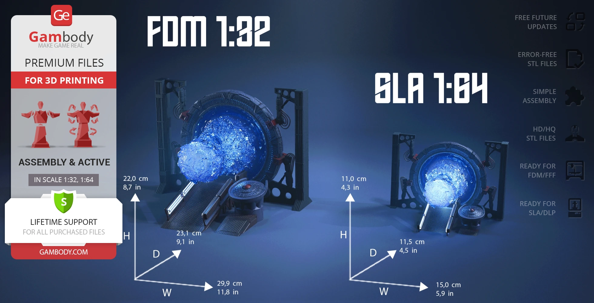
- Sizes for:
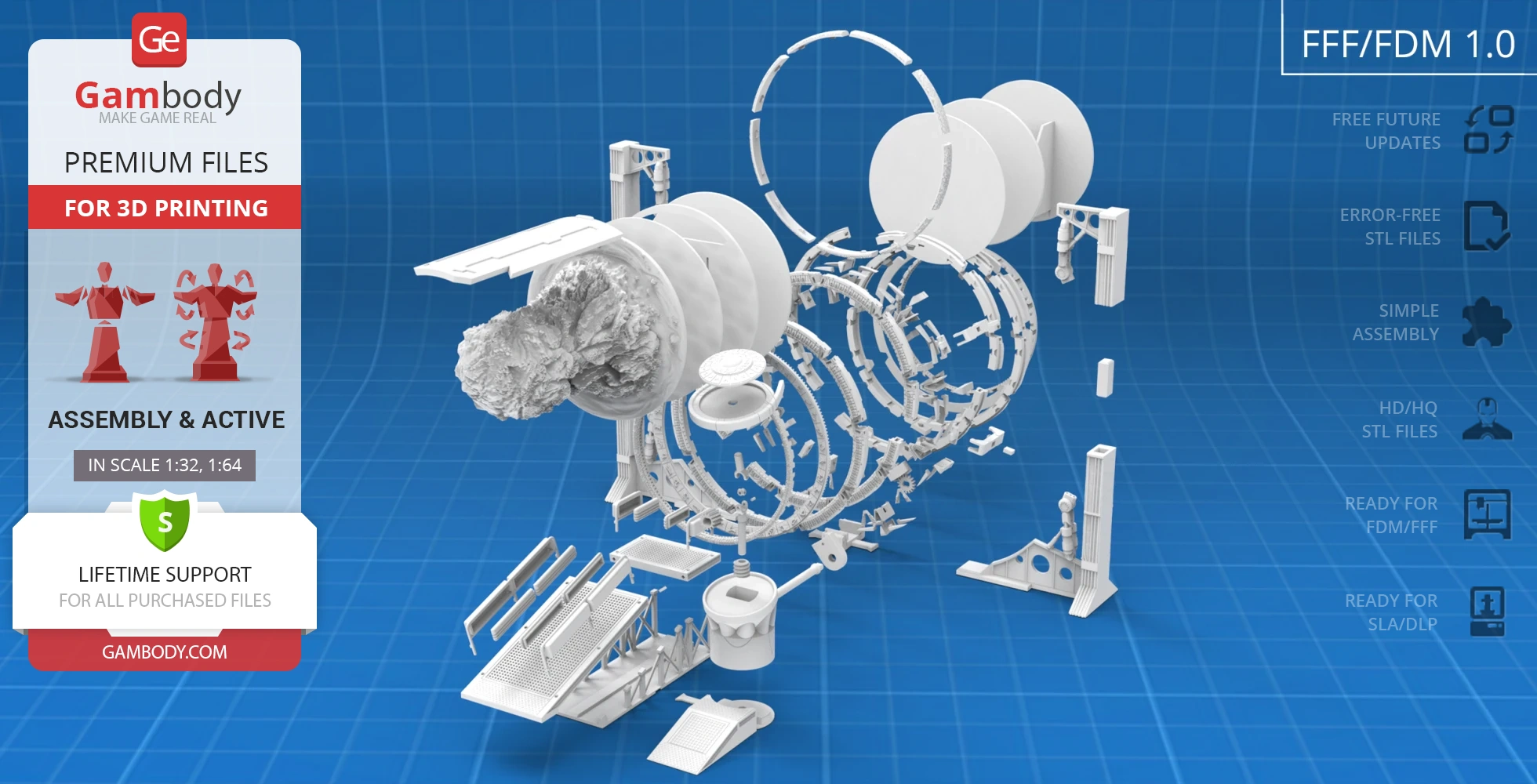
- FFF/FDM: 220 mm tall, 299 mm wide, 231 mm deep;
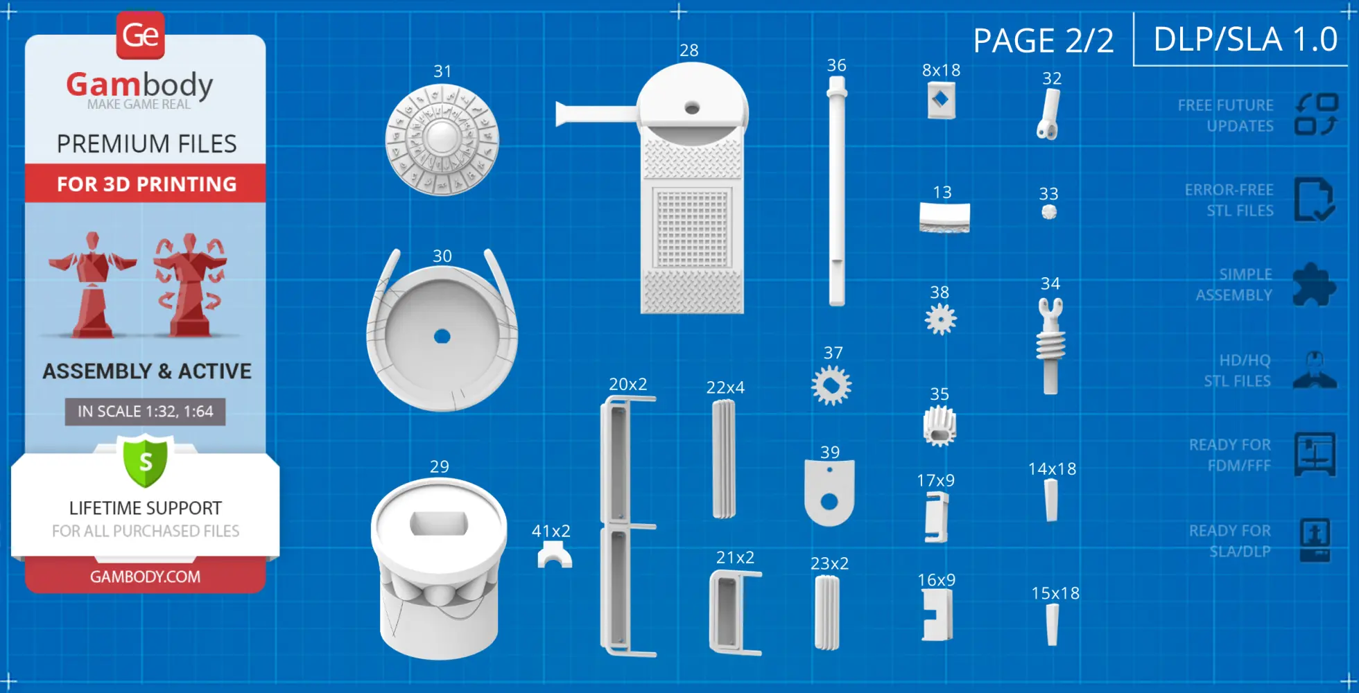
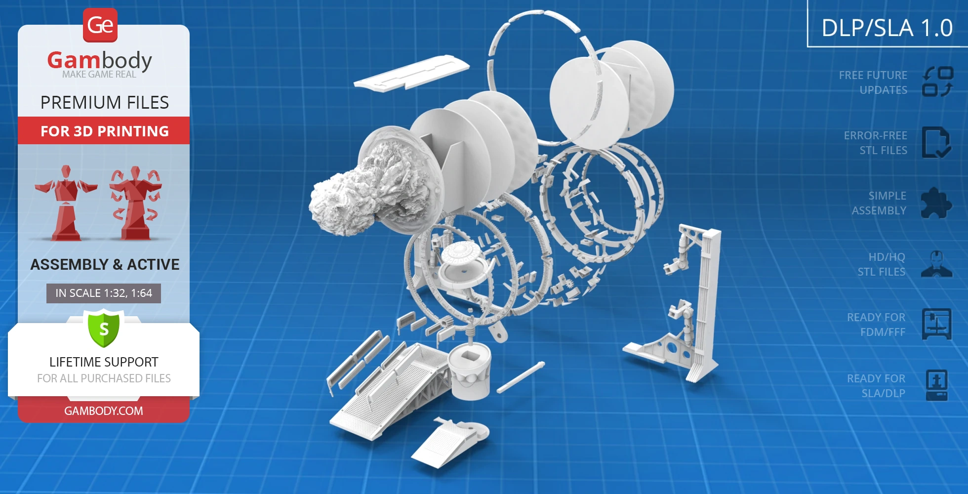
- DLP/SLA: 110 mm tall, 150 mm wide, 115 mm deep;
- Assembly Manual for FFF/FDM 1.0 and DLP/SLA 1.0 versions in PDF and video formats;
- Detailed settings that we provide as a recommendation for Cura, Bambu Studio, Simplify3D, Slic3r and PrusaSlicer for the best print;
- Full technical support from the Gambody Support Team.
Detailed information about this 3D printing model is available in the DESCRIPTION section.
Before printing, take a look at Printing Details for recommended settings and tips to achieve better results.
ABOUT THIS 3D MODEL
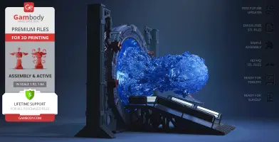
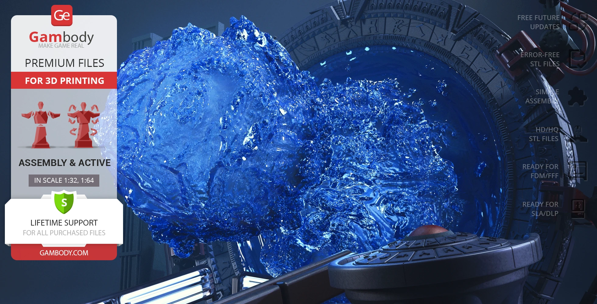
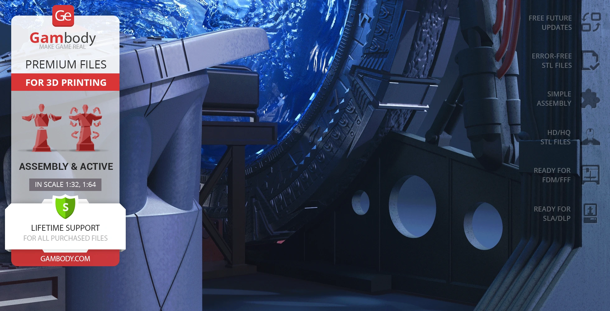
The plot of the sci-fi television series Stargate SG-1 revolves around the powerful portal devices called stargates. Stargate is a mechanism consisting of hyper-advanced large rings that allow intergalactic travel; it is operated with the help of a special dialing system which allows to set the coordinates of a specific space location and generates a stable wormhole for the space journey. Being under the constant threat from the hostile Goa'uld race, the earthlings establish secret military teams, with SG-1 as a flagship team, to carry out exploration missions through the stargate to find methods of resistance to the Goa'uld.
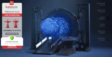
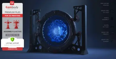
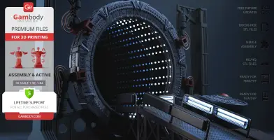
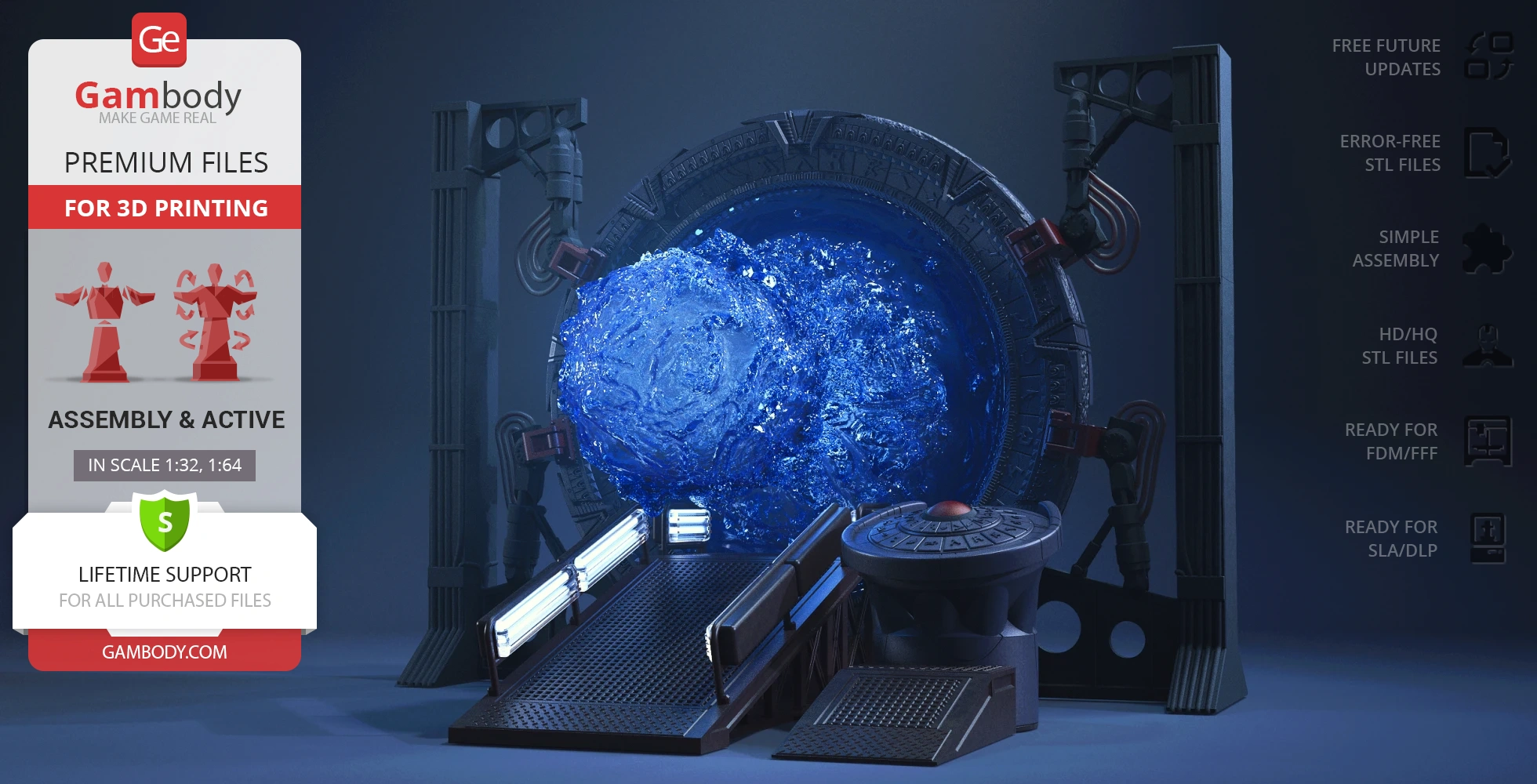
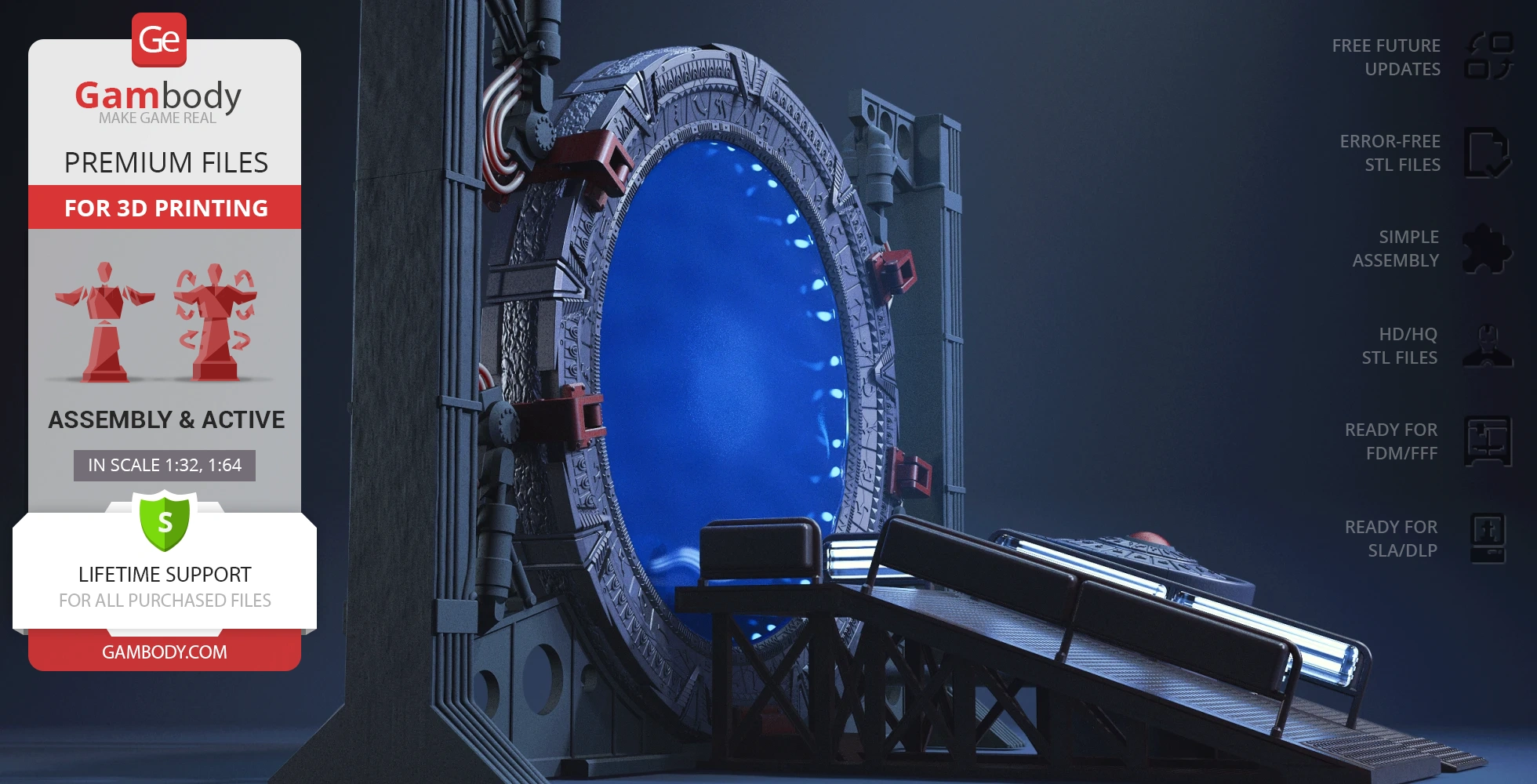
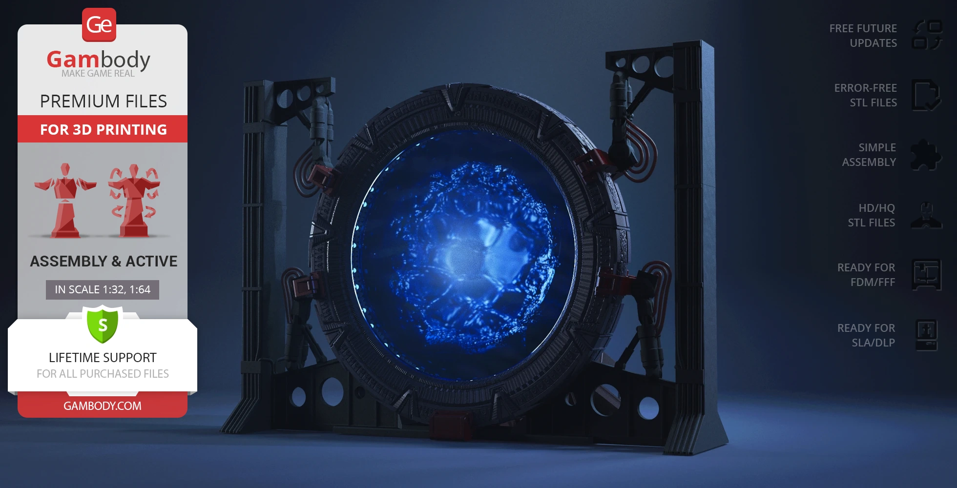
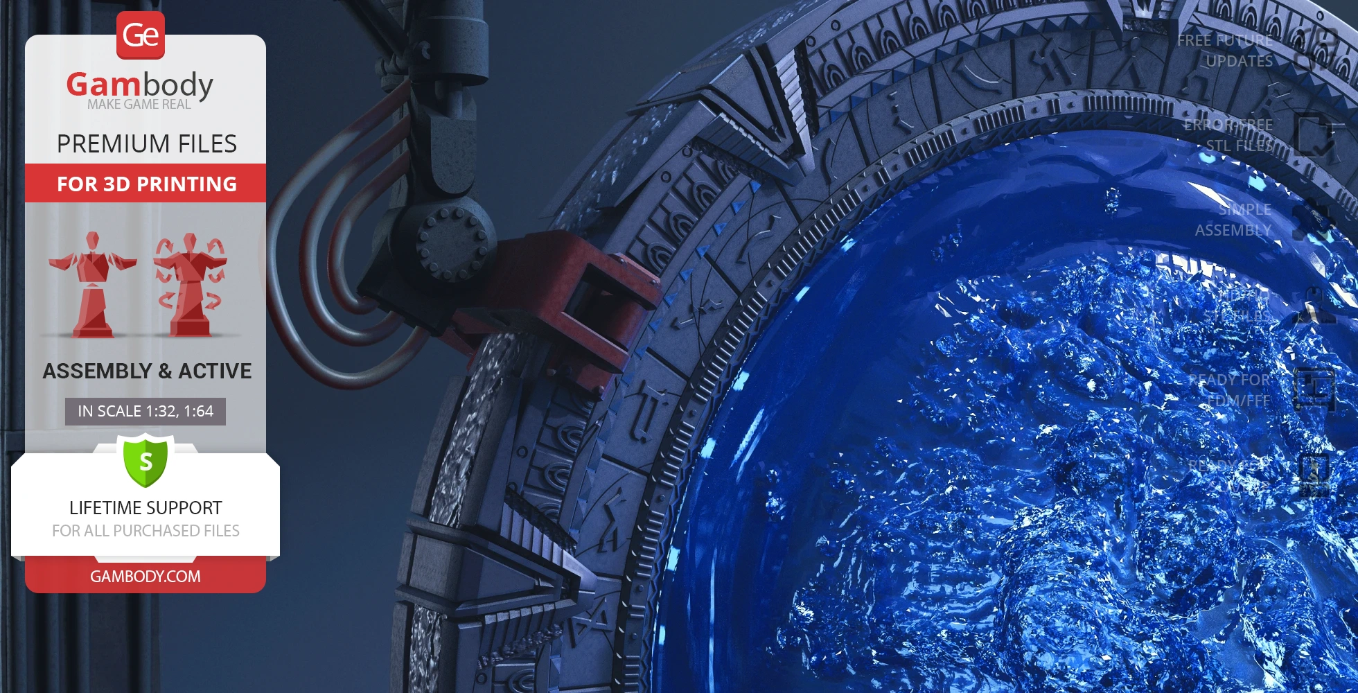
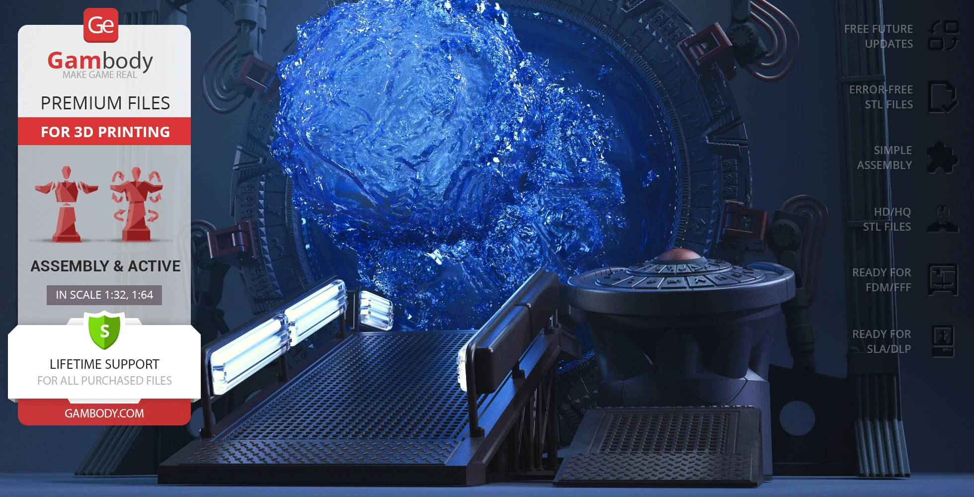
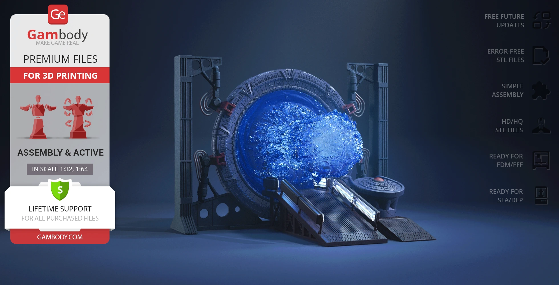
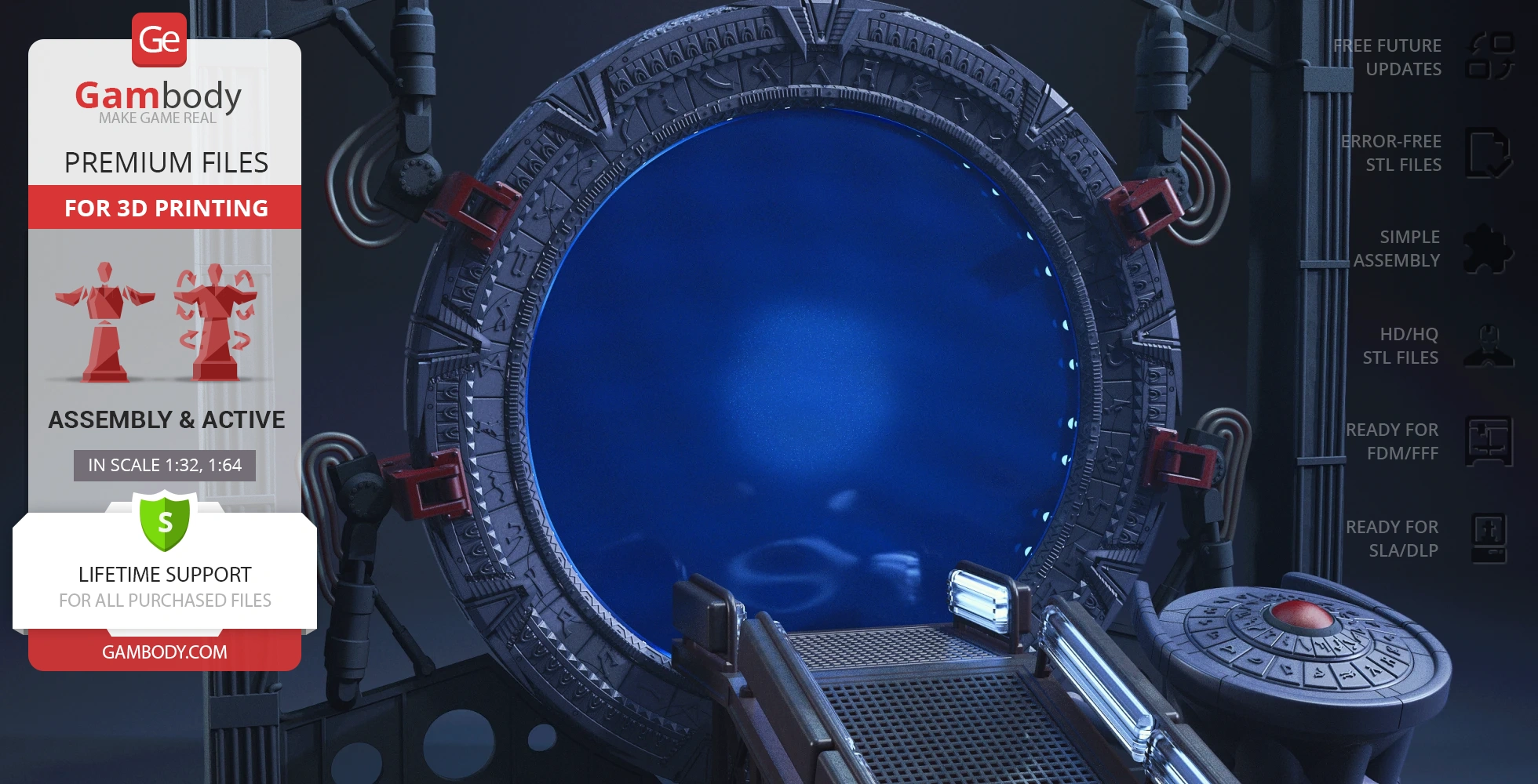
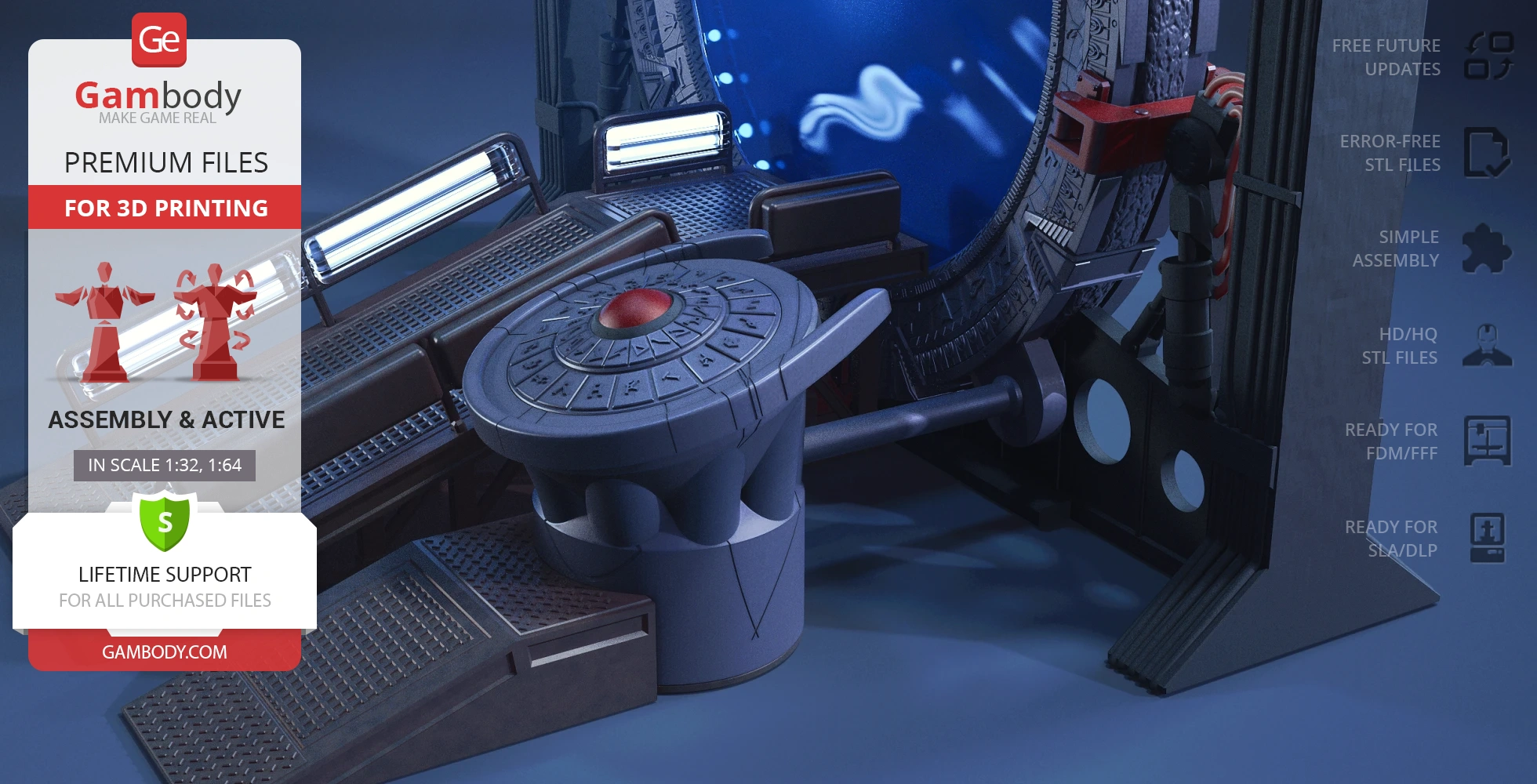
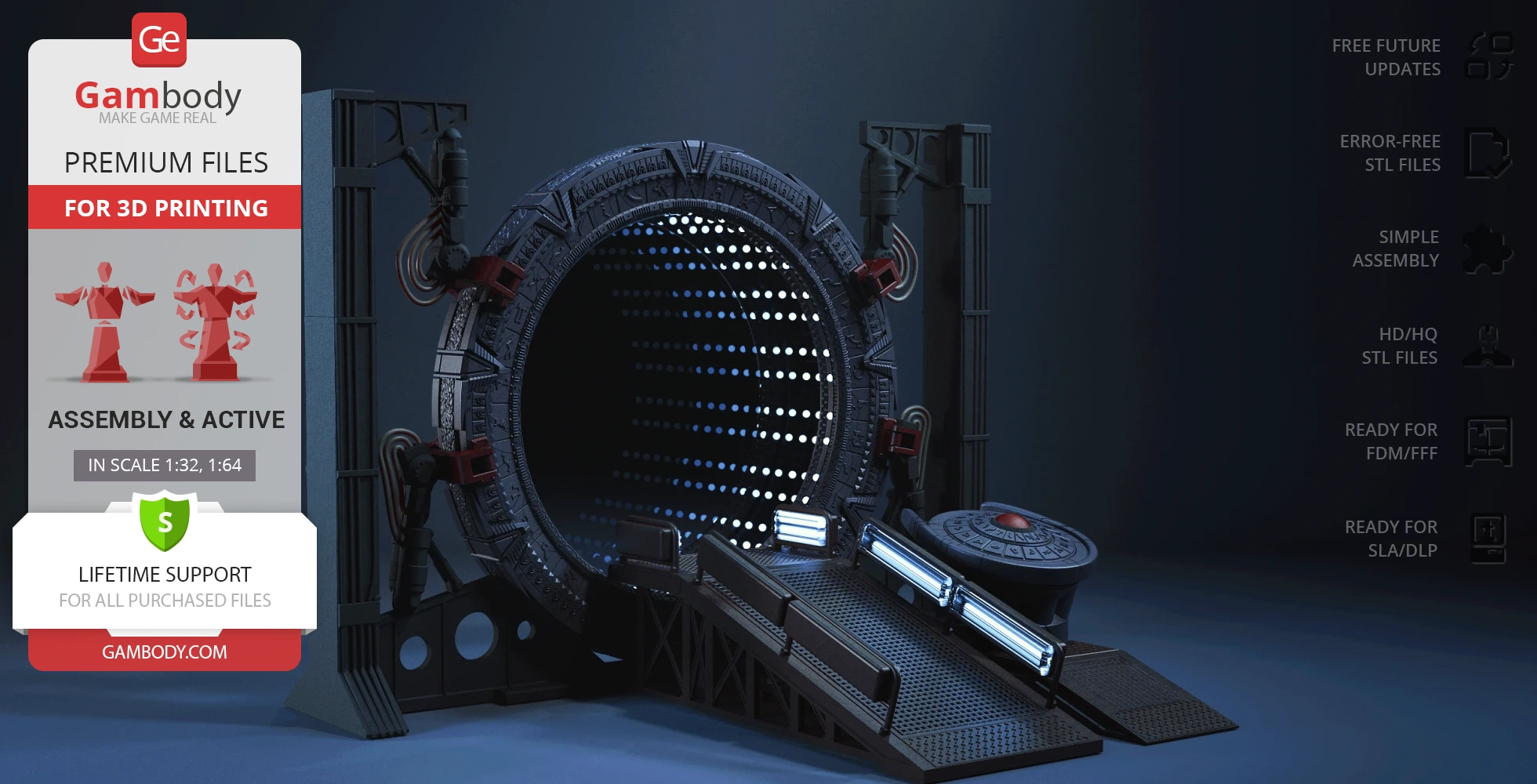
The Stargate 3D printing model from our contributor is an example of meticulous and skillful work. The 3D artist managed to recreate the portal device with great precision, and, besides the thought-out model building, you can see such details as alternative wormhole designs, ring engravings, and active control panel articulation mechanisms, among others. And our Team of moderators made sure that the STLs are top-quality so the model is perfectly adapted for 3D printing. Watch your printing dream become reality with the legendary Stargate!
ADAPTATION FOR 3D PRINTING
The Stargate model for 3D printing is an active assembly model and its moderation and adaptation for different types of 3D printers took the Gambody team 109 hours in total.
For you to receive the cleanest 3D printing result possible, minimize the amount of filament needed for generated support, and make use of the active elements designed by Gambody Engineers, the device was divided into convenient assembly parts.
All assembly parts in the FFF/FDM 1.0 version are provided in STL files in recommended positions that were worked out in order to ensure the smoothness of the details’ surfaces after printing and that the 3D printing beginners won’t face difficulties when placing the parts on a build plate. When downloading any model’s file you will also receive “Assembly Manual” for FFF/FDM 1.0 and DLP/SLA 1.0 versions in PDF and video formats. We highly recommend that you get acquainted with the “Assembly Video” and “Assembly Manual” before getting down to the Stargate 3D printing model.
The model is saved in STL files, a format supported by most 3D printers. All STL files for 3D printing have been checked in Netfabb and no errors were shown.
The model’s scale was calculated from the diameter of the Stargate. The 3D printing model’s chosen scales are 1:32 for the FFF/FDM version and 1:64 for the DLP/SLA version.
VERSIONS’ SPECIFICATIONS
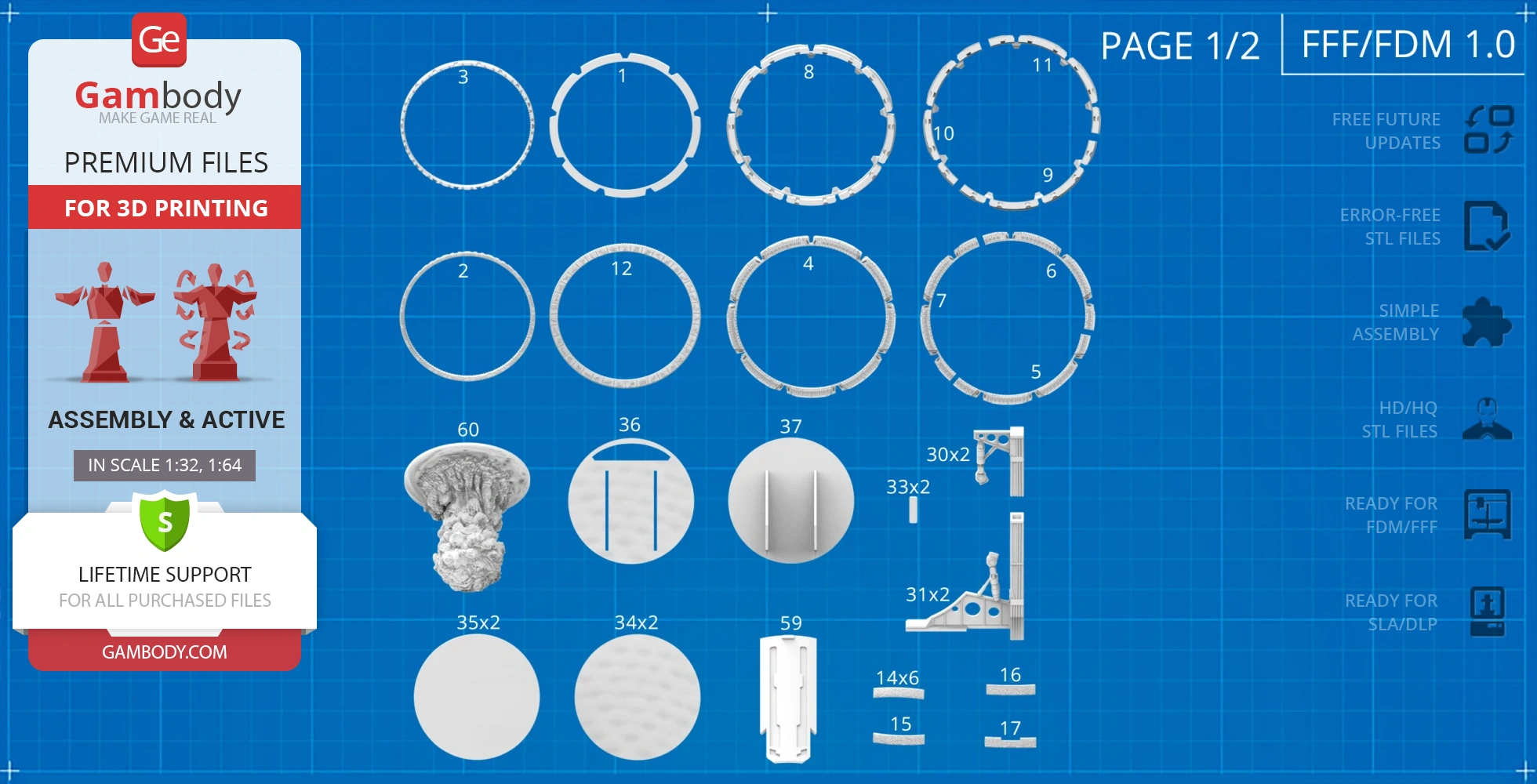
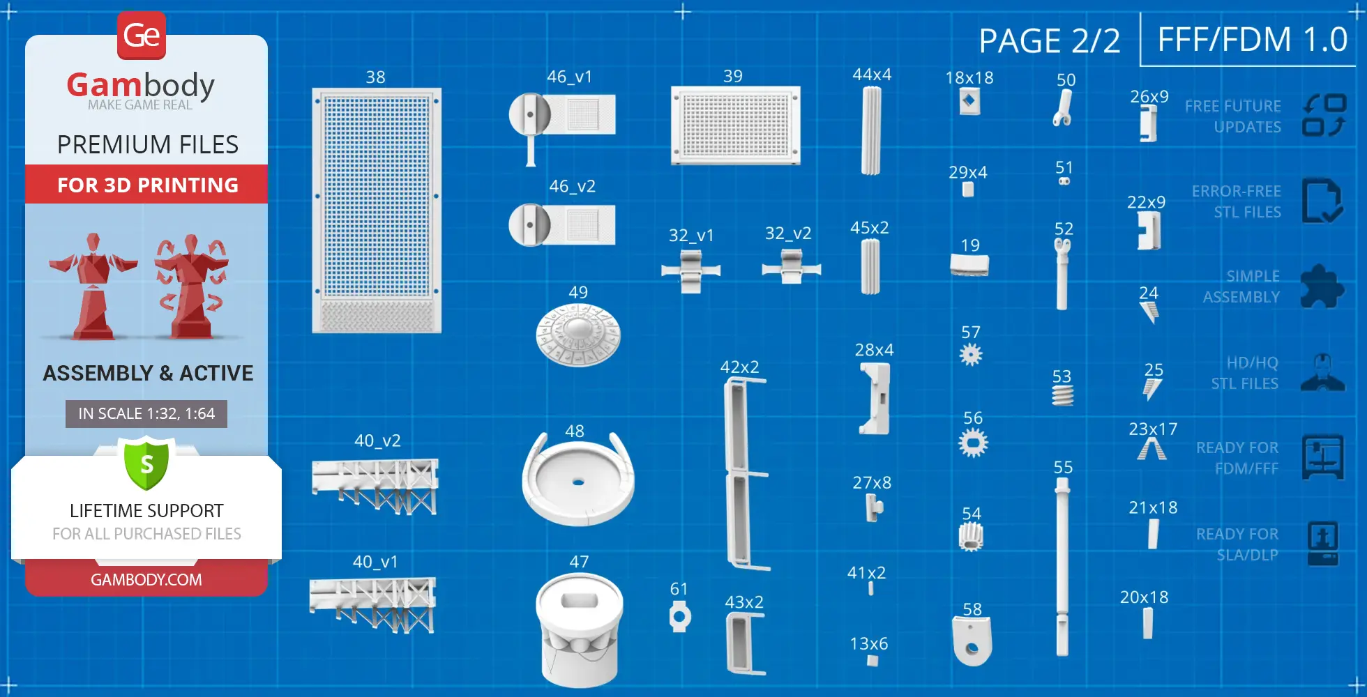
FFF/FDM 1.0 version features:
- Contains 60 parts;
- A printed model is 220 mm tall, 299 mm wide, 231 mm deep;
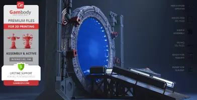
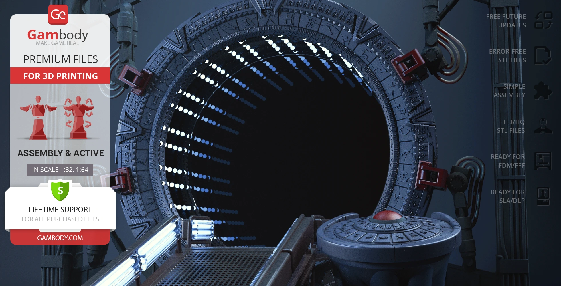
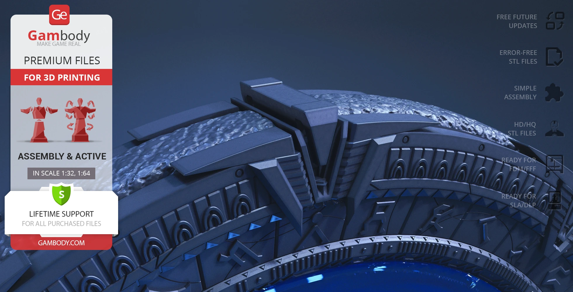
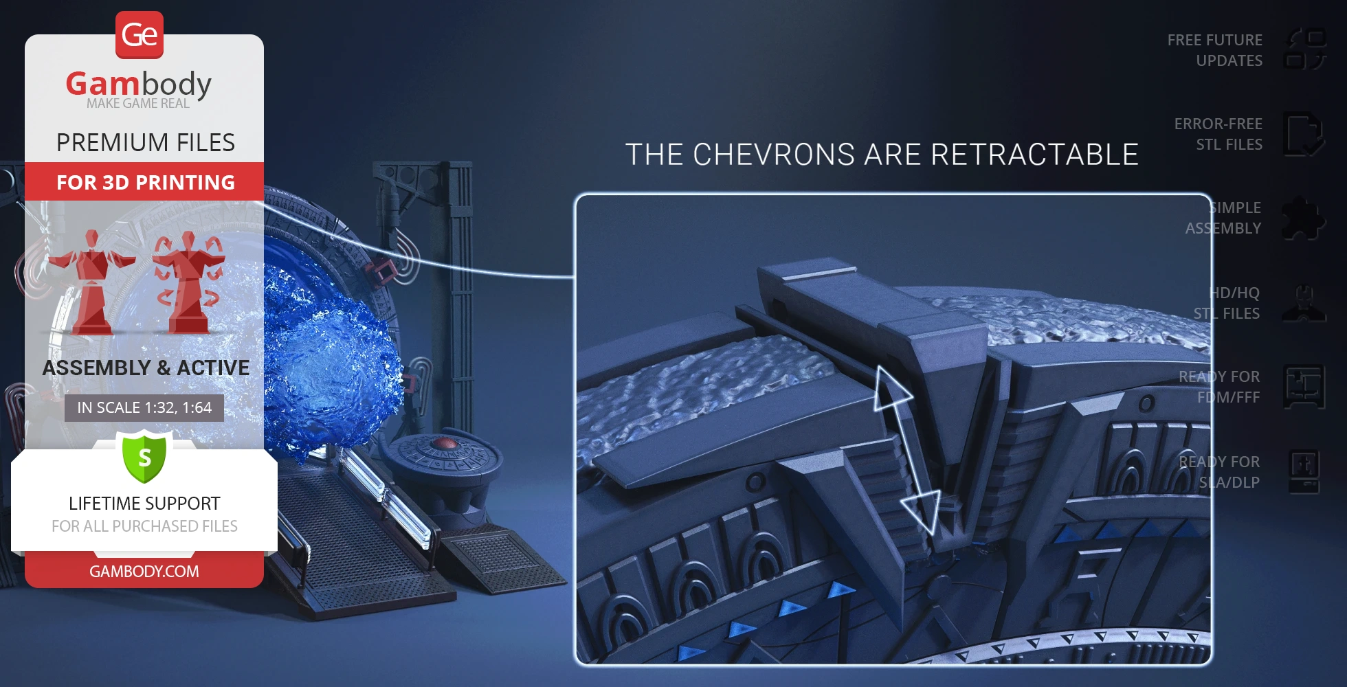
- Retractable chevrons;
- 2 variants of the ring: solid and comprised of 3 parts;
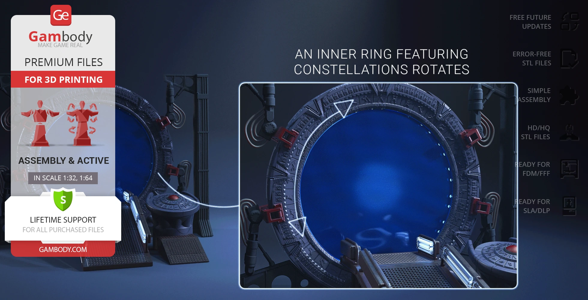
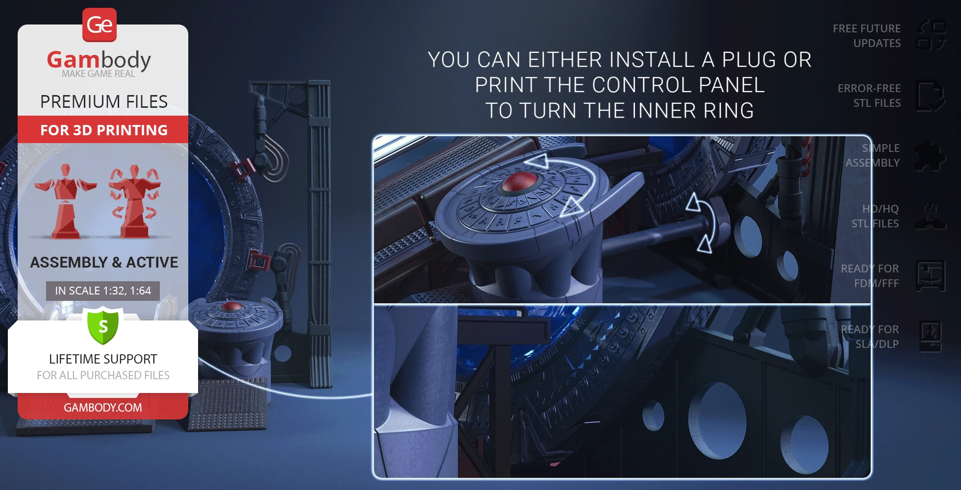
- An inner ring featuring constellations rotates;
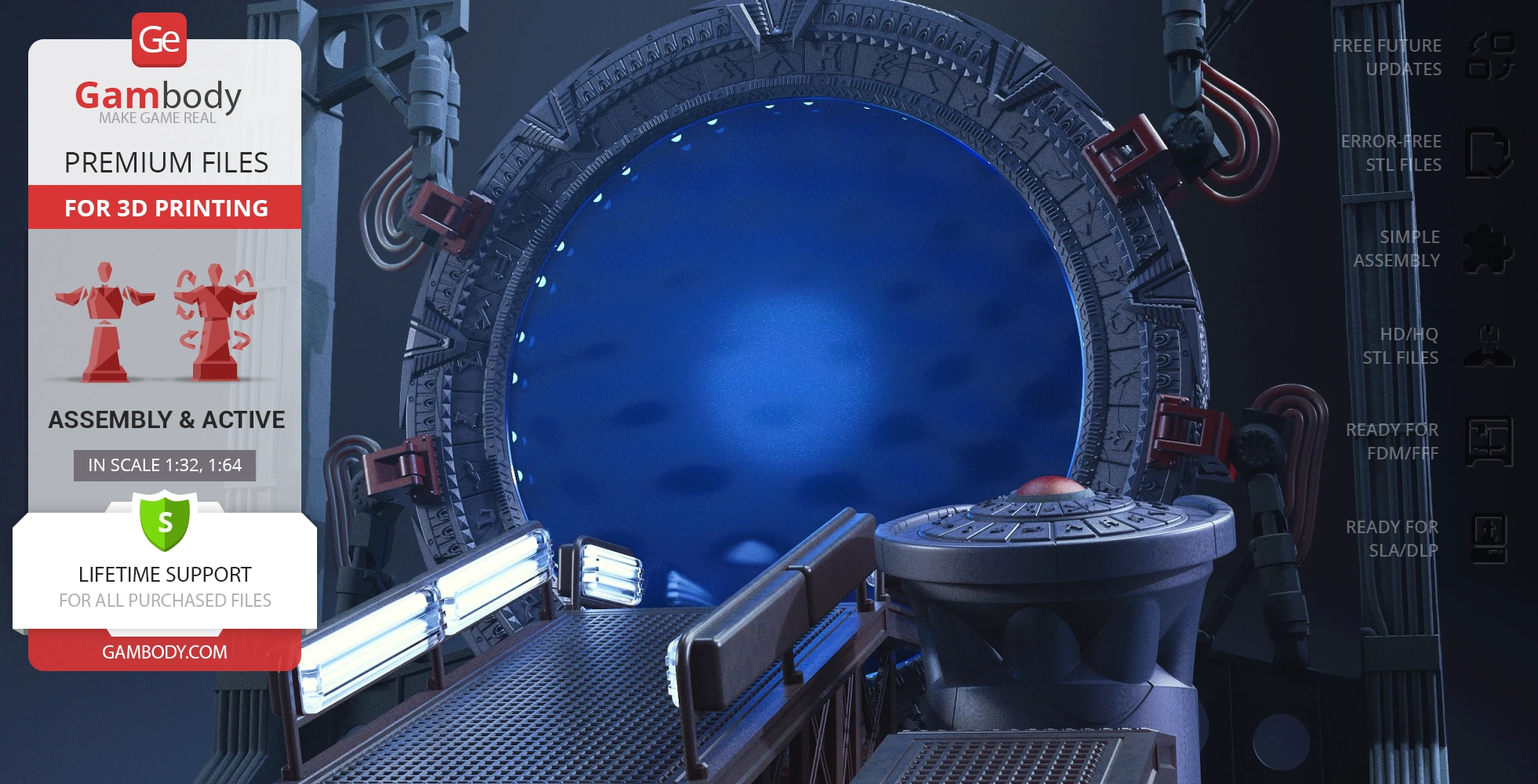
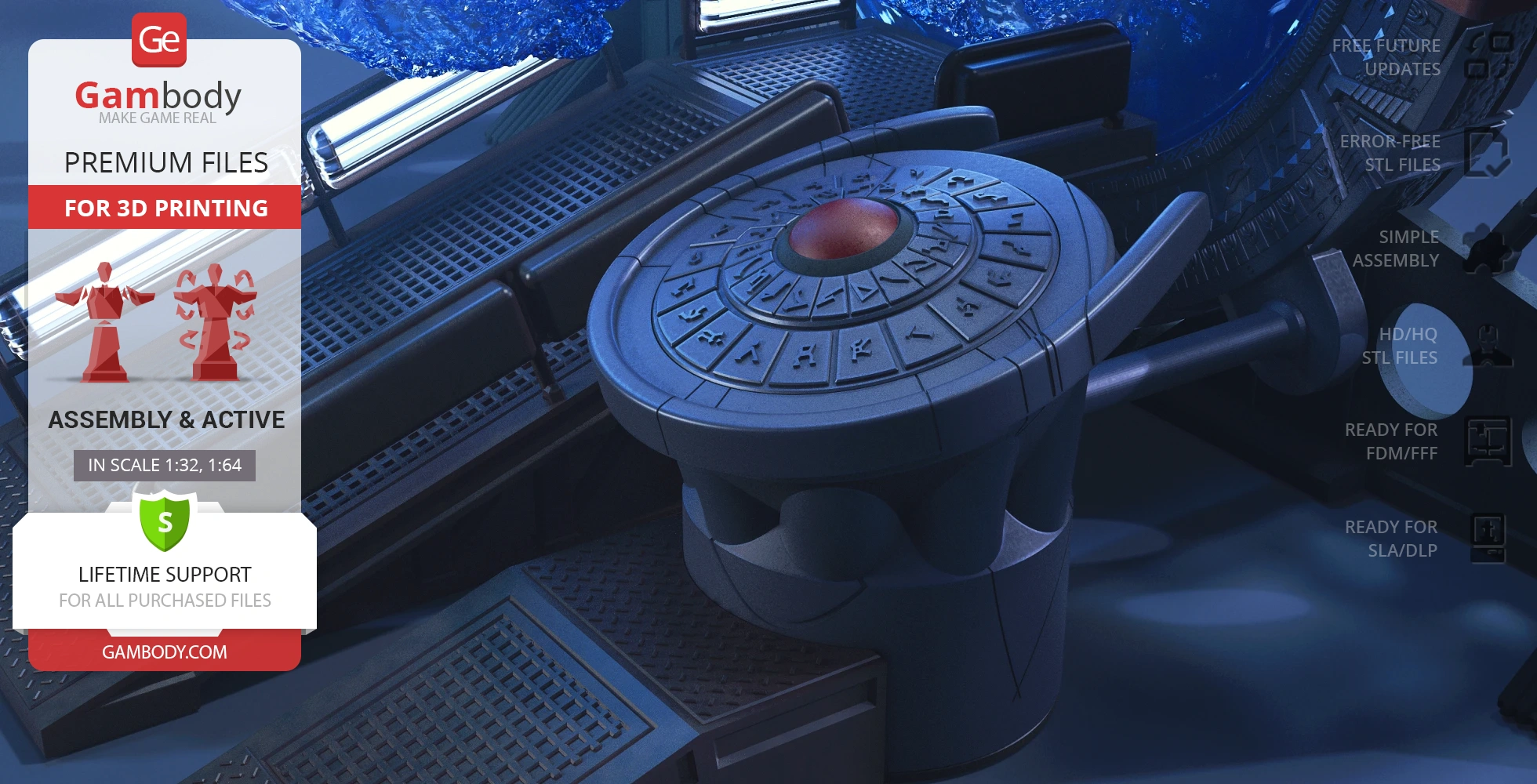
- You can optionally install the Stargate Atlantis control panel to have the opportunity to rotate the portal;
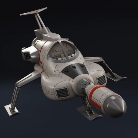
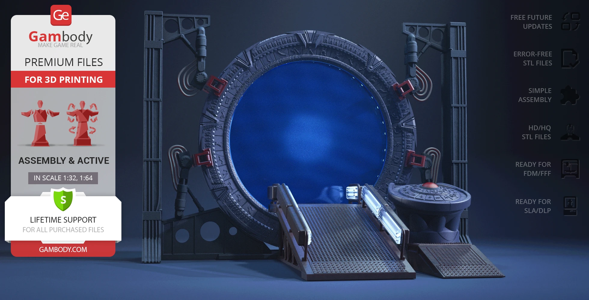
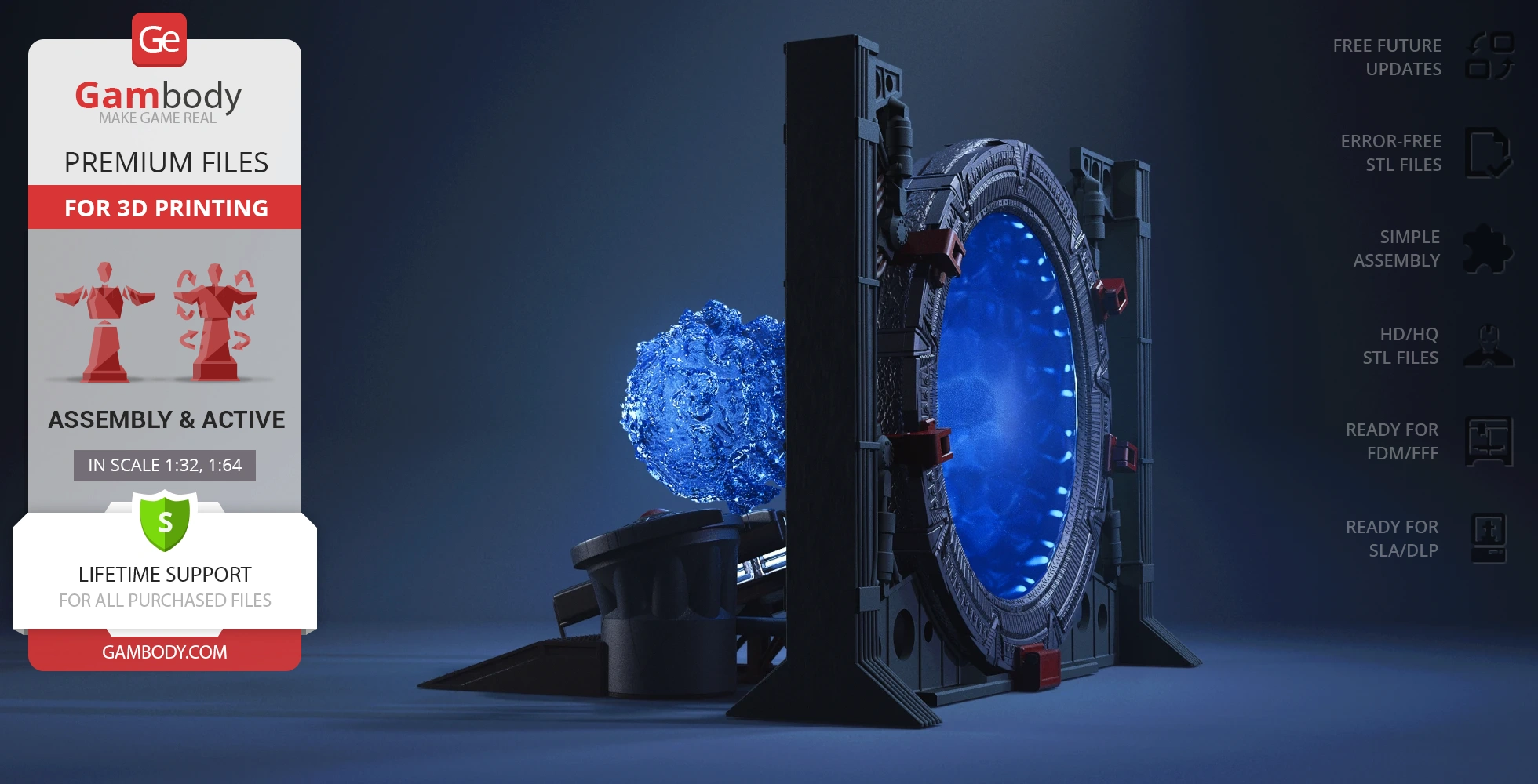
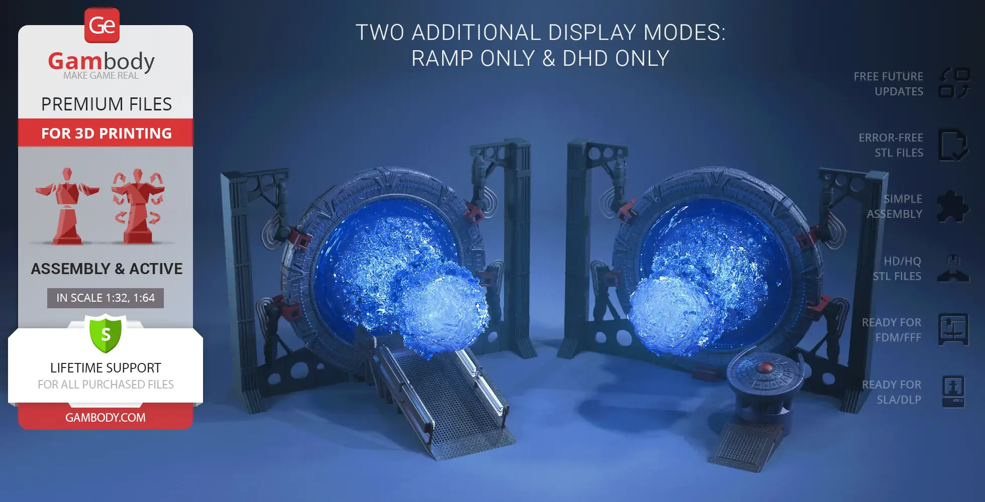
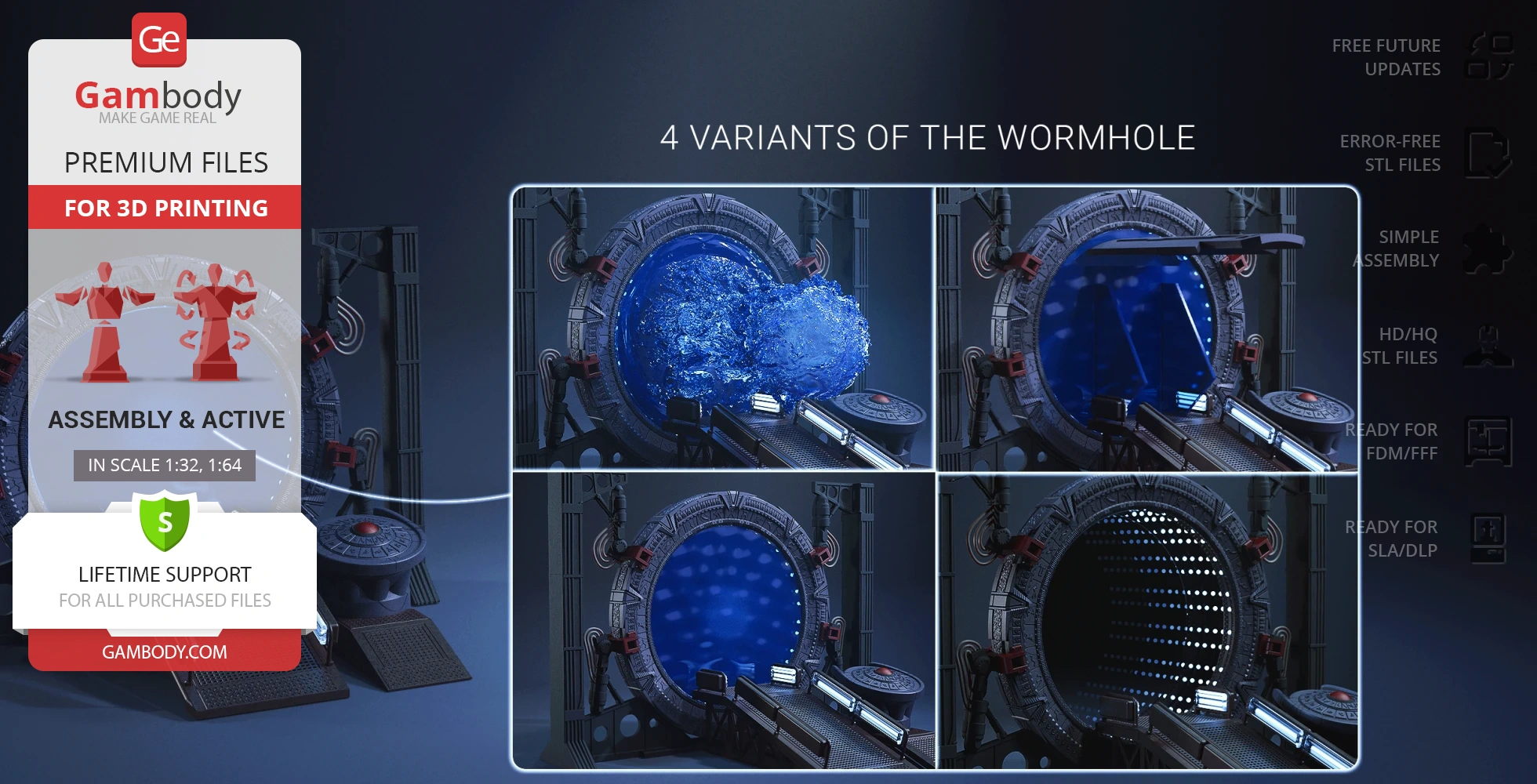
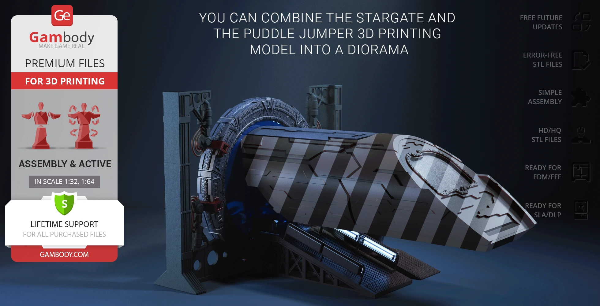
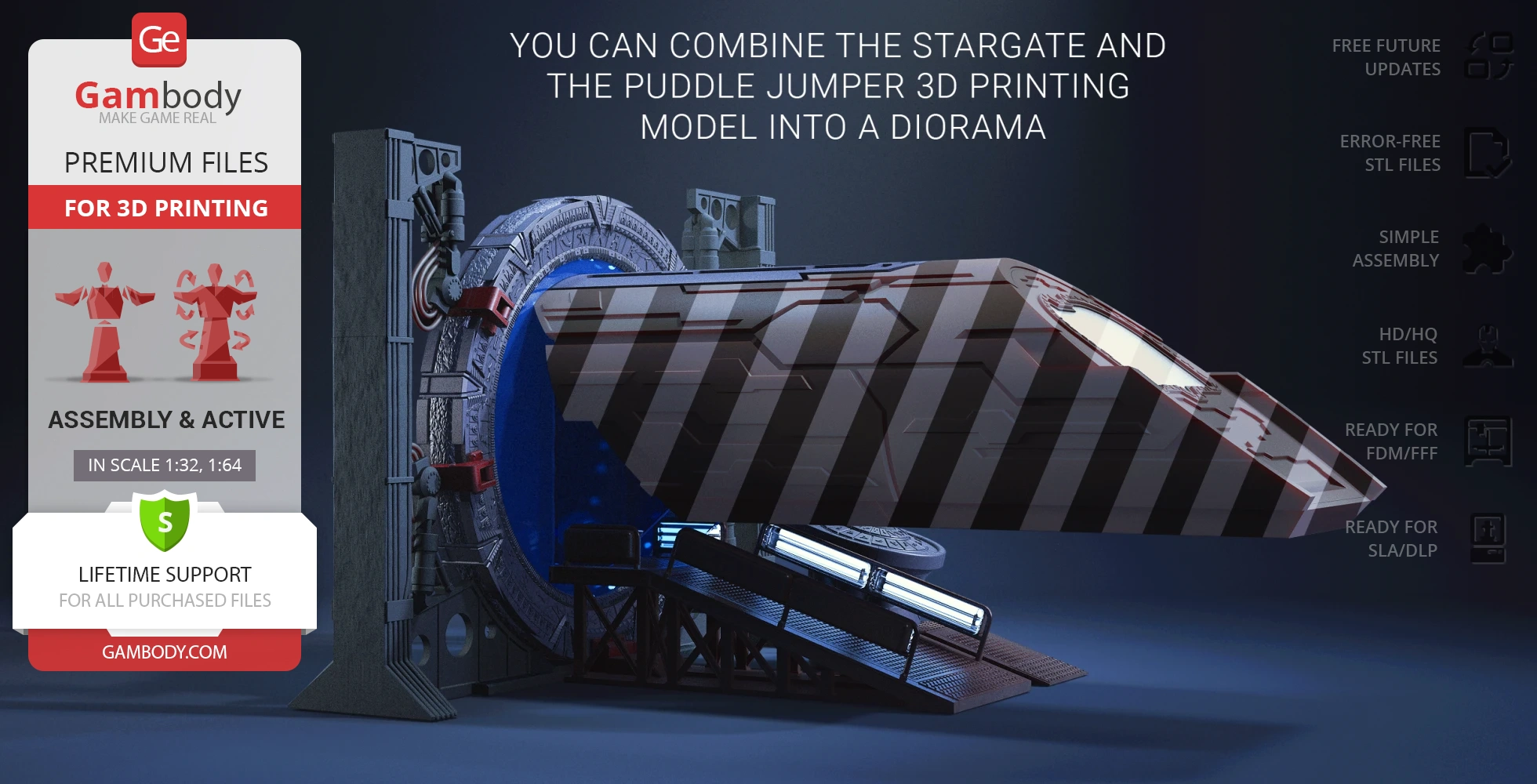
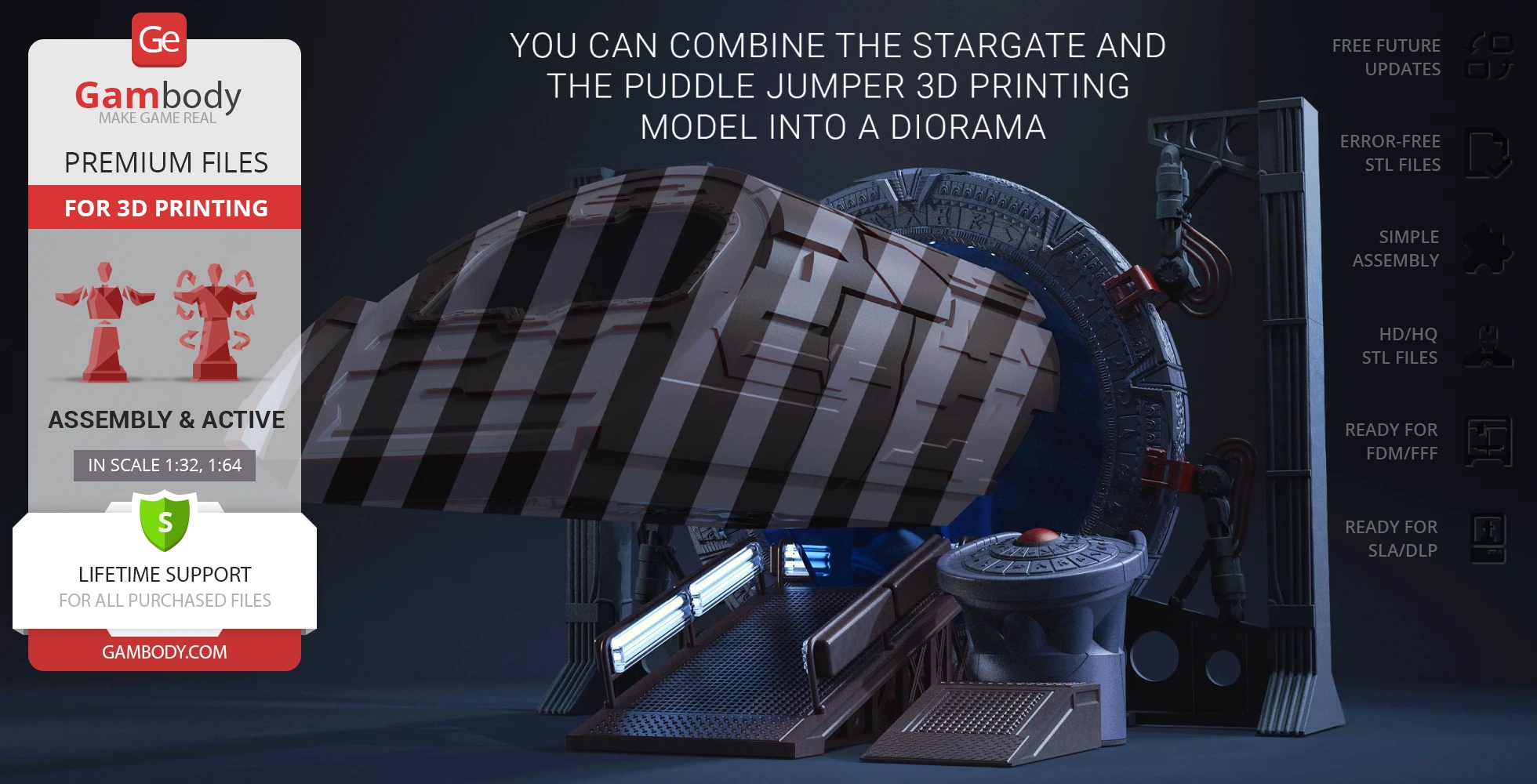
- 4 variants of the wormhole: a smooth part, a part with a ripple effect, a part with a vortex effect, and a part designed to combine the Stargate andPuddle Jumper into a diorama. Puddle Jumper can be purchased as a separate item;
- The PLA wires can be replaced with standard wires;
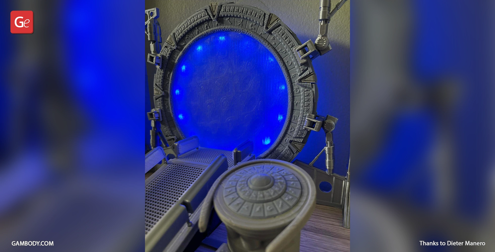
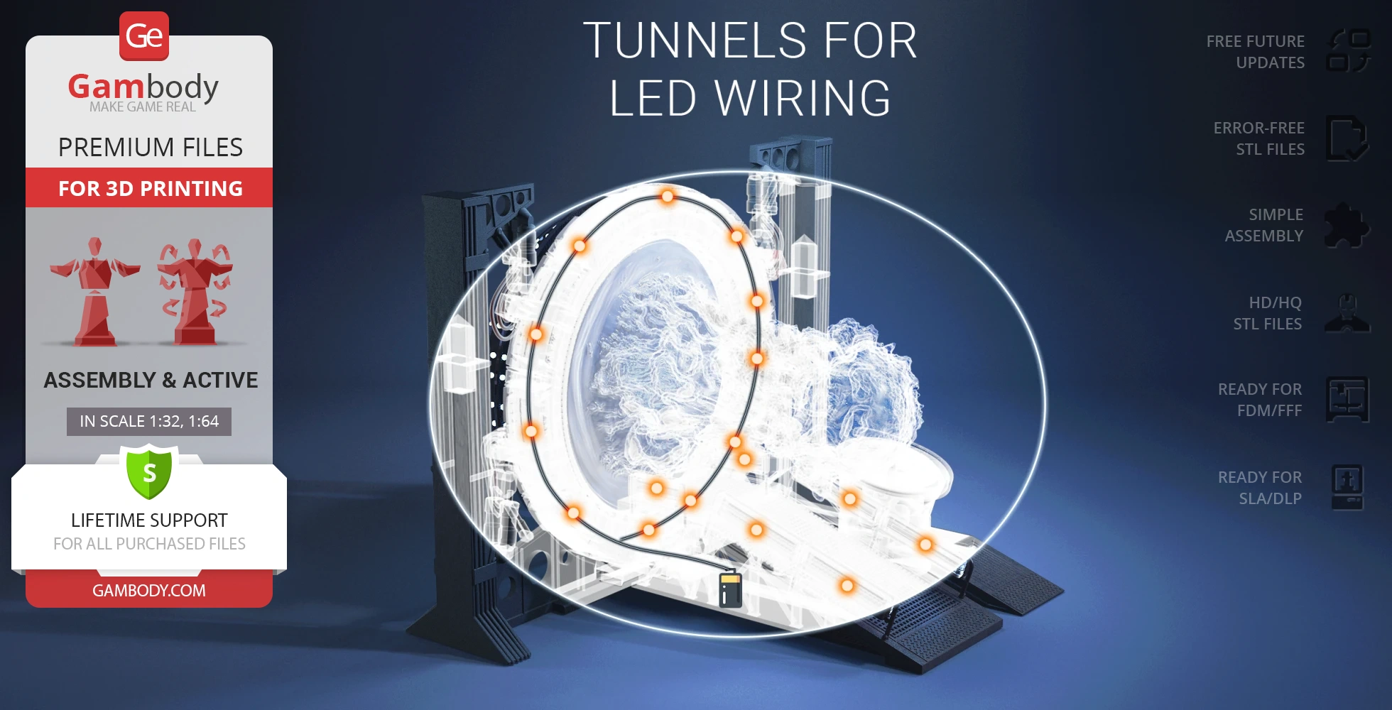
- There are tunnels for LED wiring to light up the ring inside and handrails;
- All parts are divided in such a way that you will print them with the smallest number of support structures.
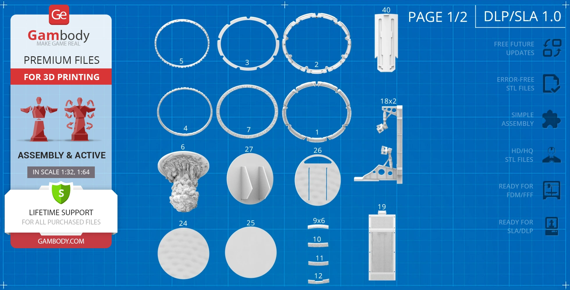
DLP/SLA 1.0 version features:
- Contains 40 parts;
- A printed model is 110 mm tall, 150 mm wide, 115 mm deep;
- Retractable chevrons;
- 2 variants of the ring: solid and comprised of 3 parts;
- An inner ring featuring constellations rotates;
- You can optionally install the Stargate Atlantis control panel to have the opportunity to rotate the portal;
- 4 variants of the wormhole: a smooth part, a part with a ripple effect, a part with a vortex effect, and a part designed to combine the Stargate and Puddle Jumper into a diorama;
- The PLA wires can be replaced with standard wires;
- There are tunnels for LED wiring to light up the ring inside and handrails;
- All parts are divided in such a way to fit the build plates and to ensure that support structures are generated where needed.
You can get the Stargate model for 3D printing immediately after the purchase! Just click the green Buy button in the top-right corner of the model’s page. You can pay with PayPal or your credit card.
Watch the tutorial on how to assemble a Stargate 3D Printing Model onGambody YouTube channel.
Also, you may like Puddle Jumper3D Printing Model and other Sci-Fi3D Printing Models.
________
FAQ:
Average customer rating (14 reviews)
4.2
Ratings breakdown
Click a star rating to filter reviews
Overall experience
Level of detail in the model
4.3
Model cut quality and assembly guide
4.1
Clarity and accuracy of the model page
4.2
Level of detail in the model
4.5
Model cut quality and assembly guide
4.6
Clarity and accuracy of the model page
4.7
Level of detail in the model
5
Model cut quality and assembly guide
4
Clarity and accuracy of the model page
4
Your Stargate project turned out amazing, and it's even hard to believe that this is your first 3D printed build! Keep up the great job:)
As for the tighter fitment in some areas, some connections are intentionally made a bit tighter for more secure assembly, although depending on printer calibration, a bit of sanding or cleanup may occasionally be needed. If a part feels excessively tight, we also generally recommend slightly scaling down the connecting part by around 1%, which usually helps.
We also really appreciate your feedback regarding the instructions. In the specific case you mentioned with the first gate ring, both versions are intended for the exact same assembly and functionality. The ring is divided into three parts simply as an alternative option for those who decide to scale the model up and use printers with smaller print beds, so the larger ring can still fit for printing.
Whenever there are different assembly options specifically related to functionality or different build scenarios, we always try to clearly mention that in the instructions. But if you have any specific pages or examples where something felt unclear or could use a better explanation, we’d really appreciate it if you could send them to us at support@gambody.com.
Your feedback is genuinely very important for us, and we always review it carefully to continue improving both the models and the instructions.
And by the way, you’re very welcome to share your Stargate build in our 3D printing community on Facebook as well: https://www.facebook.com/groups/183216945475583.
There are already quite a lot of Stargate fans and makers there sharing both their finished builds and work-in-progress photos, so we’re sure many people in the community would really enjoy seeing your result too :)
Thank you for choosing Gambody, and good luck with your next project!
Level of detail in the model
4.5
Model cut quality and assembly guide
4.5
Clarity and accuracy of the model page
4.5
Level of detail in the model
3.5
Model cut quality and assembly guide
2.4
Clarity and accuracy of the model page
4
Chevrons mechanism
The chevrons are designed to be movable and include two fixation positions: open and closed. However, at the standard scale and when printed in FDM, the lifting mechanism may not perform exactly as intended due to the relative softness of filament materials. Better results can be achieved by printing these parts in high-quality resin or at a larger scale.
At the standard scale, we recommend deciding in advance whether you’d like the chevrons displayed in the open or closed position and fixing them in place with glue. Please also note that for proper internal lighting, the chevrons should remain closed.
Regarding screen accuracy, you are correct that the small size of the parts does not allow for a fully illuminated chevron design identical to the TV series. Additionally, it’s worth noting that in the feature film — unlike the series — the chevrons are not illuminated at all.
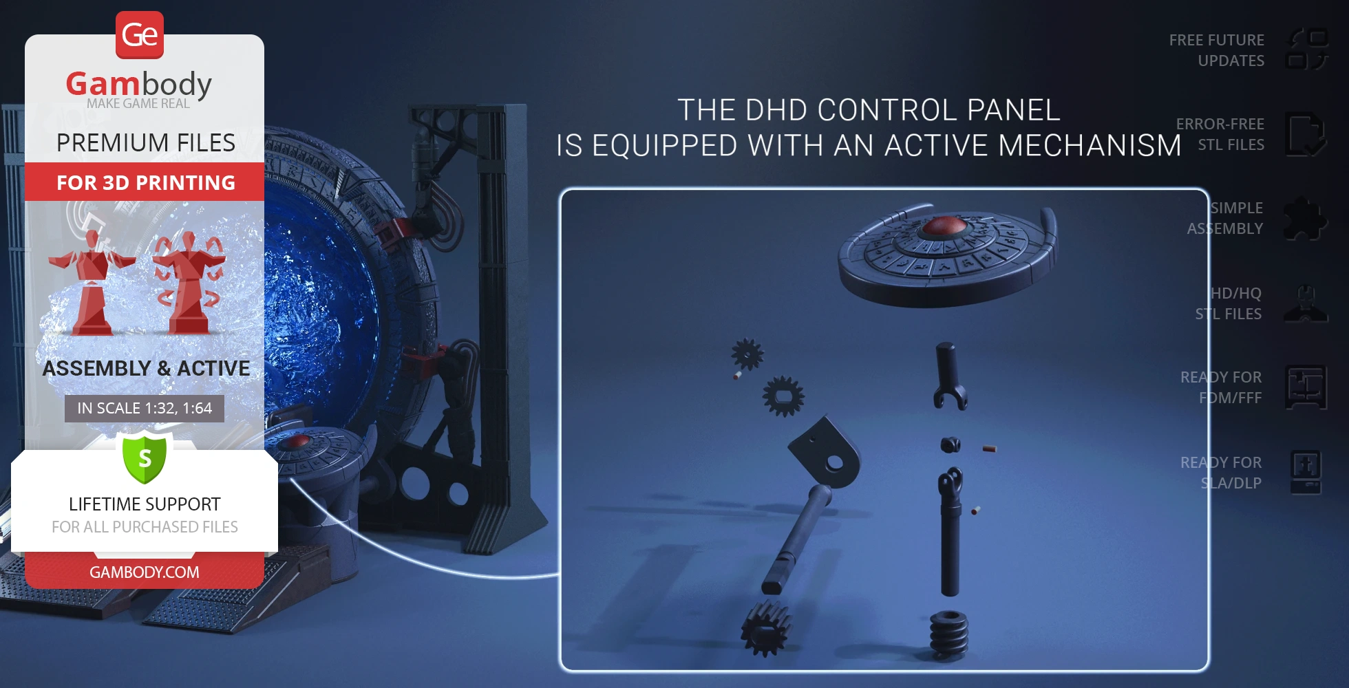
DHD turning mechanism
This is a precision mechanism that requires careful assembly. For best results, we recommend the following:
- Shafts and gears should rotate freely with light manual force
- Shafts should be printed with at least 50% infill and 3 outer walls
- Gears should be glued to their corresponding shafts (#53 to #52 and #54 to #55) to eliminate excess movement
- A small amount of play may still remain in parts #50–53; to reduce it further, short pieces of filament can be glued into the holes
- Using silicone lubricant is also recommended
If difficulties persist, our team can assemble and demonstrate the mechanism to help clarify how it works.
That said, to further improve the DHD mechanism, its design has already been updated:
- For FFF/FDM, part #47 was modified and a new locking part #61 was added
- For SLA, part #29 was modified and part #41 was added
Parts #4 and #8 alignment
These parts do align correctly, as confirmed by the author (see images 1–3). In most cases, the issue is related to orientation. We recommend rotating one part relative to the other by 90° or 180° to find the correct position.
For example, when parts #4 and #8 are in an incorrect orientation and rotated 90° relative to each other, they appear as shown in image 4.
If alignment issues persist after testing different orientations, this may indicate printer calibration or dimensional accuracy issues, in which case reprinting the parts after checking printer kinematics would be advised.
We hope this helps clarify the design intent and assembly details. If you need any further assistance, we’re always happy to help you achieve the best possible result with your build.
Level of detail in the model
5
Model cut quality and assembly guide
5
Clarity and accuracy of the model page
5
Level of detail in the model
4
Model cut quality and assembly guide
4
Clarity and accuracy of the model page
4
Level of detail in the model
1
Model cut quality and assembly guide
1
Clarity and accuracy of the model page
1
Level of detail in the model
3
Model cut quality and assembly guide
3
Clarity and accuracy of the model page
3
Level of detail in the model
4
Model cut quality and assembly guide
4
Clarity and accuracy of the model page
4
Level of detail in the model
5
Model cut quality and assembly guide
5
Clarity and accuracy of the model page
5
Level of detail in the model
5
Model cut quality and assembly guide
5
Clarity and accuracy of the model page
5
Level of detail in the model
5
Model cut quality and assembly guide
5
Clarity and accuracy of the model page
5
Level of detail in the model
5
Model cut quality and assembly guide
5
Clarity and accuracy of the model page
5
Level of detail in the model
5
Model cut quality and assembly guide
5
Clarity and accuracy of the model page
5
Below you'll find detailed slicing settings for Bambu Studio 2.0+, Orca Slicer 2.0+, UltiMaker Cura 5.0+, PrusaSlicer 2.0+, Slic3r 1.3+, Simplify3D 5.0+ to help you get the best results when printing this model. These settings are optimized specifically for this 3D model, but please note they may need slight adjustments depending on your printer or filament. When in doubt, refer to your printer's user manual.
To avoid printing issues and achieve the best quality, we highly recommend applying the following settings:
For better quality use 0.12 mm layer height, for fast printing use 0.2 mm layer height. For pins and the Ge connectors, use 0.2 layer height.
120-150% of your Layer Height
But you can paint the seam if you want.
You have to calibrate this parameter
You have to calibrate this parameter
You have to calibrate this parameter
For pins and power elements of the structure, such as the vehicle frame, use 3 loop
Disabled for vehicles and enabled for characters
For 0,2 Layer Height
The parameters in this tab vary greatly, it all depends on the quality of your printer. For example, if you have a classic Ender3, stick to the minimum parameters, but if you have a newer printer, for example Anycubic cobra 3 v2, you can select the maximum recommended values
Settings for advanced users, change these parameters only if you have sufficient 3D printing expertise
Enable this parameter if your model requires supports
We also recommend placing and removing supports manually in some places using special button
1-2 loops for more thick support
Top Z distance = 1-1.3 layer Height. If the supports are hard to remove, try increasing this setting by 0.1-0,4 mm
Bottom Z distance = 1-1.3 layer Height. If the supports are hard to remove, try increasing this setting by 0.1-0,4 mm
You have to calibrate this parameter which one is better for your filament
Increase this parameter if the supports are hard to remove from walls
For PLA and PETG filament types
5-8 mm is optional for small prints that have bad adhesion to the build plate
You have to calibrate this parameter
Read the description on your filament roll
Read the description on your filament roll and increase this parameter for fast printers
Read the description on your filament roll and increase this parameter for fast printers
For better quality use 0.12 mm layer height, for fast printing use 0.2 mm layer height. For pins and the Ge connectors, use 0.2 layer height.
120-150% of your Layer Height
But you can paint the seam if you want.
0.01-0.05 You have to calibrate this parameter
0.01-0.05 You have to calibrate this parameter
0.1-0.2 You have to calibrate this parameter
For pins and power elements of the structure, such as the vehicle frame, use 3 loop
Disabled for vehicles and ships, enabled for characters
For 0,2 Layer Height
For 0,2 Layer Height
The parameters in this tab vary greatly, it all depends on the quality of your printer. For example, if you have a classic Ender3, stick to the minimum parameters, but if you have a newer printer, for example, Anycubic Kobra 3 Or Bambulab A1, you can select the maximum recommended values.
Settings for advanced users, change these parameters only if you have sufficient 3D printing expertise
Enable this parameter if your model requires supports
We also recommend placing and removing supports manually in some places using special button
Top Z distance = 1-1.3 layer Height. If the supports are hard to remove, try increasing this setting by 0.1-0,4 mm
Bottom Z distance = 1-1.3 layer Height. If the supports are hard to remove, try increasing this setting by 0.1-0,4 mm
Increase this parameter if the supports are hard to remove from walls
For PLA and PETG filament types
5-8 mm is optional for small prints that have bad adhesion to the build plate
Read the description on your filament roll
Read the description on your filament roll and increase this parameter for fast printers
You have to calibrate this parameter
Read the description on your filament roll and increase this parameter for fast printers
Read the description on your filament roll
This field is filled in according to your printer specifications when you add it to the slicer.
You can add custom G-code here for the start and end of the print. However, be careful - this is for advanced users only!
You have to calibrate your printer using Ge retraction test models
Retraction Length: For direct-drive setups use 0.5 mm to 2.5 mm; for Bowden extruders use 5 to 7 mm
This is how fast the filament is pulled back—40-60 mm/s for direct drive and 30-50 mm/s for Bowden setups.
You have to calibrate this parameter: Reduce it until the printer starts to hit the parts with the nozzle during printing, then increase it by 0.2.
For better quality use 0.12 mm layer height, for fast printing use 0.2 mm layer height. For pins and the Ge connectors, use 0.2 layer height.
120-150% of your Layer Height
To increase the strength of the print parts, use wall line count: 3
For pins and connectors use 50% Infill
These parameters are for standard PLA plastic. If you are using a different type of plastic, check the printing temperature recommended by the manufacturer. Also, read the description on your filament spool. For fast printers, add +30 °C to the current parameters.
The parameters in this tab vary greatly, it all depends on the quality of your printer. For example, if you have a classic Ender3, stick to the minimum parameters, but if you have a newer printer, for example Anycubic cobra 3 v3, you can select the maximum recommended values
Settings for advanced users, change these parameters only if you have sufficient 3D printing expertise.
You need to calibrate this parameter using Gambody test models. These values are average values for a Direct Drive extruder; for a Bowden extruder, the values should be increased.
You need to calibrate this parameter using Gambody test models. These values are average values for a Direct Drive extruder; for a Bowden extruder, the values should be increased.
Use this value other than 0 if your nozzle catches on the internal infill during travel moves. Try to keep this value as low as possible in height.
Use normal supports to support large, straight surfaces (most mechanical or technical parts).
You have to calibrate this parameter according to the capabilities of your printer and your filament, using a Gambody test models.
Use 1 instead of 0 if your supports are thin and tall. They will be harder to remove, but much stronger.
Top Z distance = 1-1.3 layer Height. If the supports are hard to remove, try increasing this setting by 0.1-0,4 mm
Increase this parameter if the supports are hard to remove from walls
Use tree supports to support complex objects, such as characters.
You have to calibrate this parameter according to the capabilities of your printer and your filament, using a Gambody test models.
Top Z distance = 1-1.3 layer Height. If the supports are hard to remove, try increasing this setting by 0.1-0,4 mm
Increase this parameter if the supports are hard to remove from walls
Use a skirt for all parts when printing on outdated printers.
Use a brim when printing thin but tall parts, as well as parts with a small bed adhesion area.
For better quality use 0.12 mm layer height, for fast printing use 0.2 mm layer height. For pins and the Ge connectors, use 0.2 layer height.
120-150% of your Layer Height
for 0.2 Layer Height
But you can paint the seam if you want.
(for PLA and PETG)
(5-8 mm is optional for small prints that have bad adhesion to the build plate)
Enable this parameter if your model requires supports
(45-50 degree)You have to calibrate this parameter according to the capabilities of your printer
and your filament, using a Gambody test models.
Top contact Z distance = 1-1.3 layer Height. If the supports are hard to remove, try
increasing this setting by 0.1-0,4 mm
Top contact Z distance = 1-1.3 layer Height. If the supports are hard to remove, try
increasing this setting by 0.1-0,4 mm
Increase this parameter if the supports are hard to remove from walls
The parameters in this tab vary greatly, it all depends on the quality of your printer. For example, if you have a classic Ender3, stick to the minimum parameters, but if you have a newer printer, for example Anycubic cobra 3 v3, you can select the maximum recommended values
Settings for advanced users, change these parameters only if you have sufficient 3D printing expertise. Use the minimum value for outdated printers without acceleration calibration, and the maximum value for modern printers if you need it.
These settings only work for 3D printers with multiple extruders
You can try setting all parameters in this section, except the First layer, to values between 0.75% of your nozzle diameter and 1.25% of your nozzle diameter. Adjusting them will help you work out the optimal parameters for the best quality for your print. As for the First layer, you can set it to 150% of the diameter of your nozzle for better adhesion to the build plate (for a nozzle with a diameter of 0.4 mm, the First layer extrusion width can be from 0.3 mm to 0.5 mm)
For better printing quality you have to calibrate this parameter using Gambody test model.
Check your filament manufacturer's temperature recommendations on the spool.
Cooling parameters depends on the material you use for printing.
*for PLA
For better quality use 0.12 mm layer height, for fast printing use 0.2 mm layer height. For pins and the Ge connectors, use 0.2 layer height.
120-150% of your Layer Height
For 0.12 Layer Height
For 0.12 Layer Height
For pins and connectors use 50% Infill
Use skirt for outdated 3d printers
(5-8 mm is optional for small prints that have bad adhesion to the build plate)
Enable this parameter if your model requires supports
(45-60 degree)You have to calibrate this parameter according to the capabilities of your printer and your filament, using a Gambody test models
Contact Z distance = 1-1.3 layer Height. If the supports are hard to remove, try increasing this setting by 0.1-0,4 mm
The parameters in this tab vary greatly, it all depends on the quality of your printer. For example, if you have a classic Ender3, stick to the minimum parameters, but if you have a newer printer, for example Anycubic cobra 3 v3, you can select the maximum recommended values
Settings for advanced users, change these parameters only if you have sufficient 3D printing expertise. Use the minimum value for outdated printers without acceleration calibration, and the maximum value for modern printers if you need it.
You have to calibrate this parameter from 0.9 to 1.1 according to the capabilities of your printer and your filament, using a Gambody test models.
Check your filament manufacturer's temperature recommendations on the spool.
Cooling parameters depends on the material you use for printing.
Calibrate this value if you need to reduce or improve the adhesion between the plastic and the heat bed
Your current nozzle diameter
You need to calibrate this parameter using Gambody test models. These values are average values for a Direct Drive extruder; for a Bowden extruder, the values should be increased.
Your current nozzle diameter
You have to calibrate this parameter using Gambody test models.
You need to calibrate this parameter using Gambody test models. These values are average values for a Direct Drive extruder; for a Bowden extruder, the values should be increased.
For better quality use 0.12 mm layer height, for fast printing use 0.2 mm layer height. For pins and the Ge connectors, use 0.2 layer height.
For 0,2 Layer Height
For 0,2 Layer Height
To increase the strength of the print parts, use Outline Perimeters: 3
You can enable this parameter to print rounded or spherical models, as well as character models.
Use this option only if your parts are too tight. but better calibrate your printer extrusion
Use this option only if your parts are too tight. but better calibrate your printer extrusion
Use 2 and more if you want to create skirt instead brim
1-2 for skirt and 10-20 for brim
Use for wipe nozzle if you need
Use For ABS filament
For pins and connectors use 50% Infill
Top Z distance = 1-1.3 layer Height. If the supports are hard to remove, try increasing this setting by 0.1-0,4 mm
Calibrate your filament and detect optimal temperature for it
Average temperature for PLA filament
The parameters in this tab vary greatly, it all depends on the quality of your printer. For example, if you have a classic Ender3, stick to the minimum parameters, but if you have a newer printer, for example Anycubic cobra 3 v3, you can select the maximum recommended values
Settings for advanced users, change these parameters only if you have sufficient 3D printing expertise.