The total number of 3D model files available across all versions and updates of this model, including variants optimized for different types of 3D printers.
You will get instant access to the STL files of Tiger I Tank 3D Printing Model | Assembly after completing your purchase. Simply add the model to your cart and check out using PayPal, credit or debit card, Apple Pay, Google Pay, Alipay, or other available payment methods.
Watch the assembly video for Tiger I Tank 3D Printing Model | Assembly, and explore more tutorials, behind-the-scenes content, 3D printing timelapses, and painting guides on the official Gambody YouTube channel.
Source Files
This 3D model consists of files in StereoLithography (.Stl) format that have been optimized for 3D printing.
Before printing the files, we strongly recommend reading the PRINTING DETAILS section.
Important
Before printing, take a look at Printing Details for recommended settings and tips to achieve better results.
--Select printer type--
FFF/FDM
Selected
The model is optimized for 3D printing on FFF/FDM printers using filament as the amount of support structures during printing and to ensure that each part fits on an average-sized print bed.
View update history
--Select model version--
1.0
Selected
Initial
File name
Size (mm | in)
Size(mb)
Printing Time / Filament
T54,T55 Connector.stl 5 x 8 x 3 mm | 0.2 x 0.31 x 0.12 in
Size: 5 x 8 x 3 mm | 0.2 x 0.31 x 0.12 in
File size: 0.11 mb
Printing Time / Filament: 2 min / <1 m
T53 Toolbox cover left.stl 14 x 11 x 2 mm | 0.55 x 0.43 x 0.08 in
Size: 14 x 11 x 2 mm | 0.55 x 0.43 x 0.08 in
File size: 0.00 mb
Printing Time / Filament: 4 min / <1 m
T52 Toolbox cover right.stl 14 x 11 x 2 mm | 0.55 x 0.43 x 0.08 in
Size: 14 x 11 x 2 mm | 0.55 x 0.43 x 0.08 in
File size: 0.00 mb
Printing Time / Filament: 3 min / <1 m
T51 Toolbox.stl 41 x 17 x 19 mm | 1.61 x 0.67 x 0.75 in
Size: 41 x 17 x 19 mm | 1.61 x 0.67 x 0.75 in
File size: 0.21 mb
Printing Time / Filament: 1 h 4 min / 1 m
T50 Captain door axis.stl 3 x 12 x 7 mm | 0.12 x 0.47 x 0.28 in
Size: 3 x 12 x 7 mm | 0.12 x 0.47 x 0.28 in
File size: 0.02 mb
Printing Time / Filament: 2 min / <1 m
T49 Captain door.stl 13 x 13 x 4 mm | 0.51 x 0.51 x 0.16 in
Size: 13 x 13 x 4 mm | 0.51 x 0.51 x 0.16 in
File size: 0.14 mb
Printing Time / Filament: 5 min / <1 m
T48 Captain observation hole.stl 24 x 24 x 9 mm | 0.94 x 0.94 x 0.35 in
Size: 24 x 24 x 9 mm | 0.94 x 0.94 x 0.35 in
File size: 0.16 mb
Printing Time / Filament: 23 min / <1 m
T47 Loading hand door.stl 15 x 13 x 2 mm | 0.59 x 0.51 x 0.08 in
Size: 15 x 13 x 2 mm | 0.59 x 0.51 x 0.08 in
File size: 0.09 mb
Printing Time / Filament: 3 min / <1 m
T46 exhaust vent.stl 9 x 9 x 4 mm | 0.35 x 0.35 x 0.16 in
Size: 9 x 9 x 4 mm | 0.35 x 0.35 x 0.16 in
File size: 0.07 mb
Printing Time / Filament: 3 min / <1 m
T45 Bevel top cover.stl 61 x 22 x 7 mm | 2.4 x 0.87 x 0.28 in
Size: 61 x 22 x 7 mm | 2.4 x 0.87 x 0.28 in
File size: 0.02 mb
Printing Time / Filament: 37 min / <1 m
T44 Loading the hand observation mirror.stl 9 x 7 x 6 mm | 0.35 x 0.28 x 0.24 in
Size: 9 x 7 x 6 mm | 0.35 x 0.28 x 0.24 in
File size: 0.01 mb
Printing Time / Filament: 5 min / <1 m
T43 Top cover.stl 65 x 45 x 3 mm | 2.56 x 1.77 x 0.12 in
Size: 65 x 45 x 3 mm | 2.56 x 1.77 x 0.12 in
File size: 0.11 mb
Printing Time / Filament: 36 min / <1 m
T42 Main gun mouth welding joints upper.stl 49 x 4 x 3 mm | 1.93 x 0.16 x 0.12 in
Size: 49 x 4 x 3 mm | 1.93 x 0.16 x 0.12 in
File size: 0.00 mb
Printing Time / Filament: 5 min / <1 m
T41 Gunner observation hole.stl 11 x 7 x 5 mm | 0.43 x 0.28 x 0.2 in
Size: 11 x 7 x 5 mm | 0.43 x 0.28 x 0.2 in
File size: 0.10 mb
Printing Time / Filament: 5 min / <1 m
T40 Loading the hand to observe the hole.stl 11 x 7 x 5 mm | 0.43 x 0.28 x 0.2 in
Size: 11 x 7 x 5 mm | 0.43 x 0.28 x 0.2 in
File size: 0.10 mb
Printing Time / Filament: 5 min / <1 m
T39 Gunner turret turning hand wheel.stl 18 x 9 x 3 mm | 0.71 x 0.35 x 0.12 in
Size: 18 x 9 x 3 mm | 0.71 x 0.35 x 0.12 in
File size: 0.20 mb
Printing Time / Filament: 4 min / <1 m
T38 Turret direction instrument.stl 6 x 10 x 3 mm | 0.24 x 0.39 x 0.12 in
Size: 6 x 10 x 3 mm | 0.24 x 0.39 x 0.12 in
File size: 0.06 mb
Printing Time / Filament: 2 min / <1 m
T37 Turret turn the hand wheel base.stl 8 x 7 x 8 mm | 0.31 x 0.28 x 0.31 in
Size: 8 x 7 x 8 mm | 0.31 x 0.28 x 0.31 in
File size: 0.08 mb
Printing Time / Filament: 7 min / <1 m
T36 Turret turn hand wheel.stl 5 x 5 x 6 mm | 0.2 x 0.2 x 0.24 in
Size: 5 x 5 x 6 mm | 0.2 x 0.2 x 0.24 in
File size: 0.17 mb
Printing Time / Filament: 2 min / <1 m
T35 Captain seat back.stl 8 x 9 x 3 mm | 0.31 x 0.35 x 0.12 in
Size: 8 x 9 x 3 mm | 0.31 x 0.35 x 0.12 in
File size: 0.01 mb
Printing Time / Filament: 2 min / <1 m
T34 Captain seat.stl 10 x 14 x 2 mm | 0.39 x 0.55 x 0.08 in
Size: 10 x 14 x 2 mm | 0.39 x 0.55 x 0.08 in
File size: 0.09 mb
Printing Time / Filament: 3 min / <1 m
T33 Captain seat coupler.stl 6 x 13 x 6 mm | 0.24 x 0.51 x 0.24 in
Size: 6 x 13 x 6 mm | 0.24 x 0.51 x 0.24 in
File size: 0.00 mb
Printing Time / Filament: 6 min / <1 m
T32 Emergency door shaft.stl 6 x 6 x 9 mm | 0.24 x 0.24 x 0.35 in
Size: 6 x 6 x 9 mm | 0.24 x 0.24 x 0.35 in
File size: 0.01 mb
Printing Time / Filament: 4 min / <1 m
T31 Emergency escape door.stl 14 x 14 x 4 mm | 0.55 x 0.55 x 0.16 in
Size: 14 x 14 x 4 mm | 0.55 x 0.55 x 0.16 in
File size: 0.17 mb
Printing Time / Filament: 8 min / <1 m
T30 Main gun mouth welding joints lower.stl 49 x 4 x 3 mm | 1.93 x 0.16 x 0.12 in
Size: 49 x 4 x 3 mm | 1.93 x 0.16 x 0.12 in
File size: 0.00 mb
Printing Time / Filament: 5 min / <1 m
T29 Base small connector right.stl 5 x 3 x 4 mm | 0.2 x 0.12 x 0.16 in
Size: 5 x 3 x 4 mm | 0.2 x 0.12 x 0.16 in
File size: 0.01 mb
Printing Time / Filament: 2 min / <1 m
T28 Base small connector left.stl 5 x 3 x 4 mm | 0.2 x 0.12 x 0.16 in
Size: 5 x 3 x 4 mm | 0.2 x 0.12 x 0.16 in
File size: 0.01 mb
Printing Time / Filament: 2 min / <1 m
T27 Main gun base left.stl 29 x 20 x 13 mm | 1.14 x 0.79 x 0.51 in
Size: 29 x 20 x 13 mm | 1.14 x 0.79 x 0.51 in
File size: 0.03 mb
Printing Time / Filament: 37 min / <1 m
T26 Main gun base right.stl 29 x 20 x 12 mm | 1.14 x 0.79 x 0.47 in
Size: 29 x 20 x 12 mm | 1.14 x 0.79 x 0.47 in
File size: 0.03 mb
Printing Time / Filament: 37 min / <1 m
T25 Semi-circular wall.stl 66 x 43 x 20 mm | 2.6 x 1.69 x 0.79 in
Size: 66 x 43 x 20 mm | 2.6 x 1.69 x 0.79 in
File size: 0.04 mb
Printing Time / Filament: 52 min / 1 m
T24 Hanging basket floor cover.stl 14 x 25 x 1 mm | 0.55 x 0.98 x 0.04 in
Size: 14 x 25 x 1 mm | 0.55 x 0.98 x 0.04 in
File size: 0.01 mb
Printing Time / Filament: 6 min / <1 m
T23 Hanging basket floor.stl 41 x 43 x 4 mm | 1.61 x 1.69 x 0.16 in
Size: 41 x 43 x 4 mm | 1.61 x 1.69 x 0.16 in
File size: 0.25 mb
Printing Time / Filament: 27 min / <1 m
T22 Base connector.stl 8 x 8 x 5 mm | 0.31 x 0.31 x 0.2 in
Size: 8 x 8 x 5 mm | 0.31 x 0.31 x 0.2 in
File size: 0.00 mb
Printing Time / Filament: 4 min / <1 m
T21 Basket Column ago rear.stl 11 x 30 x 2 mm | 0.43 x 1.18 x 0.08 in
Size: 11 x 30 x 2 mm | 0.43 x 1.18 x 0.08 in
File size: 0.13 mb
Printing Time / Filament: 3 min / <1 m
T20 Loading the hand seat.stl 11 x 9 x 3 mm | 0.43 x 0.35 x 0.12 in
Size: 11 x 9 x 3 mm | 0.43 x 0.35 x 0.12 in
File size: 0.16 mb
Printing Time / Filament: 3 min / <1 m
T19 Loading the hand seat link.stl 10 x 9 x 2 mm | 0.39 x 0.35 x 0.08 in
Size: 10 x 9 x 2 mm | 0.39 x 0.35 x 0.08 in
File size: 0.08 mb
Printing Time / Filament: 2 min / <1 m
T18 Loading the seat backrest.stl 9 x 5 x 4 mm | 0.35 x 0.2 x 0.16 in
Size: 9 x 5 x 4 mm | 0.35 x 0.2 x 0.16 in
File size: 0.15 mb
Printing Time / Filament: 3 min / <1 m
T17 Loading the hand seat connector.stl 3 x 3 x 4 mm | 0.12 x 0.12 x 0.16 in
Size: 3 x 3 x 4 mm | 0.12 x 0.12 x 0.16 in
File size: 0.02 mb
Printing Time / Filament: 1 min / <1 m
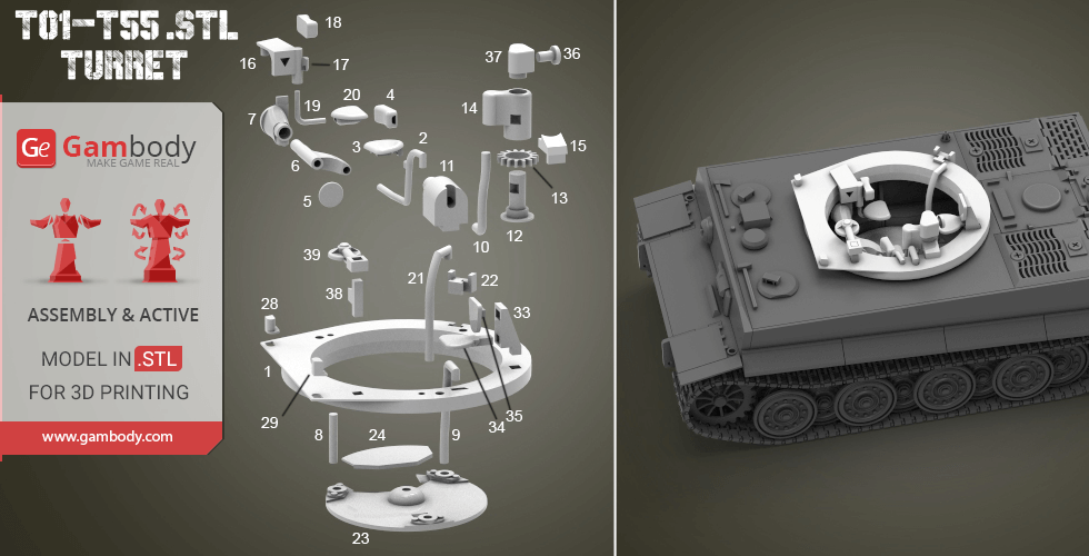
T16 Main gun angle adjustment device.stl 14 x 10 x 10 mm | 0.55 x 0.39 x 0.39 in
Size: 14 x 10 x 10 mm | 0.55 x 0.39 x 0.39 in
File size: 0.10 mb
Printing Time / Filament: 7 min / <1 m
T15 Turret rotating machine base.stl 8 x 6 x 5 mm | 0.31 x 0.24 x 0.2 in
Size: 8 x 6 x 5 mm | 0.31 x 0.24 x 0.2 in
File size: 0.01 mb
Printing Time / Filament: 3 min / <1 m
T14 Turret rotator.stl 7 x 12 x 12 mm | 0.28 x 0.47 x 0.47 in
Size: 7 x 12 x 12 mm | 0.28 x 0.47 x 0.47 in
File size: 0.19 mb
Printing Time / Filament: 12 min / <1 m
T13 Turret Rotor Gear.stl 10 x 11 x 2 mm | 0.39 x 0.43 x 0.08 in
Size: 10 x 11 x 2 mm | 0.39 x 0.43 x 0.08 in
File size: 0.12 mb
Printing Time / Filament: 2 min / <1 m
T12 Turret rotor shaft.stl 9 x 9 x 12 mm | 0.35 x 0.35 x 0.47 in
Size: 9 x 9 x 12 mm | 0.35 x 0.35 x 0.47 in
File size: 0.03 mb
Printing Time / Filament: 6 min / <1 m
T11 Turret power drive.stl 12 x 9 x 19 mm | 0.47 x 0.35 x 0.75 in
Size: 12 x 9 x 19 mm | 0.47 x 0.35 x 0.75 in
File size: 0.15 mb
Printing Time / Filament: 15 min / <1 m
T10 Turret power transmission rod.stl 27 x 10 x 2 mm | 1.06 x 0.39 x 0.08 in
Size: 27 x 10 x 2 mm | 1.06 x 0.39 x 0.08 in
File size: 0.22 mb
Printing Time / Filament: 3 min / <1 m
T09 Basket Column left.stl 12 x 30 x 2 mm | 0.47 x 1.18 x 0.08 in
Size: 12 x 30 x 2 mm | 0.47 x 1.18 x 0.08 in
File size: 0.09 mb
Printing Time / Filament: 3 min / <1 m
T08 Basket Column ago.stl 2 x 2 x 14 mm | 0.08 x 0.08 x 0.55 in
Size: 2 x 2 x 14 mm | 0.08 x 0.08 x 0.55 in
File size: 0.01 mb
Printing Time / Filament: 3 min / <1 m
T07 Main gun angle adjustment device connector1.stl 8 x 12 x 10 mm | 0.31 x 0.47 x 0.39 in
Size: 8 x 12 x 10 mm | 0.31 x 0.47 x 0.39 in
File size: 0.21 mb
Printing Time / Filament: 7 min / <1 m
T06 Main gun angle adjustment device connector2.stl 12 x 4 x 19 mm | 0.47 x 0.16 x 0.75 in
Size: 12 x 4 x 19 mm | 0.47 x 0.16 x 0.75 in
File size: 0.18 mb
Printing Time / Filament: 10 min / <1 m
T05 Main gun angle hand wheel and firing trigger.stl 7 x 7 x 4 mm | 0.28 x 0.28 x 0.16 in
Size: 7 x 7 x 4 mm | 0.28 x 0.28 x 0.16 in
File size: 0.26 mb
Printing Time / Filament: 2 min / <1 m
T04 Gunner seat backrest.stl 9 x 5 x 3 mm | 0.35 x 0.2 x 0.12 in
Size: 9 x 5 x 3 mm | 0.35 x 0.2 x 0.12 in
File size: 0.17 mb
Printing Time / Filament: 3 min / <1 m
T03 Gunner seat.stl 11 x 3 x 9 mm | 0.43 x 0.12 x 0.35 in
Size: 11 x 3 x 9 mm | 0.43 x 0.12 x 0.35 in
File size: 0.11 mb
Printing Time / Filament: 5 min / <1 m
T02 Gunner seat support rod.stl 25 x 20 x 2 mm | 0.98 x 0.79 x 0.08 in
Size: 25 x 20 x 2 mm | 0.98 x 0.79 x 0.08 in
File size: 0.20 mb
Printing Time / Filament: 3 min / <1 m
T01 Base.stl 66 x 67 x 7 mm | 2.6 x 2.64 x 0.28 in
Size: 66 x 67 x 7 mm | 2.6 x 2.64 x 0.28 in
File size: 0.11 mb
Printing Time / Filament: 59 min / 1 m
H292 Connector.stl 63 x 63 x 3 mm | 2.48 x 2.48 x 0.12 in
Size: 63 x 63 x 3 mm | 2.48 x 2.48 x 0.12 in
File size: 0.72 mb
Printing Time / Filament: 41 min / <1 m
H288-H291 Garment cover.stl 5 x 5 x 2 mm | 0.2 x 0.2 x 0.08 in
Size: 5 x 5 x 2 mm | 0.2 x 0.2 x 0.08 in
File size: 0.13 mb
Printing Time / Filament: 2 min / <1 m
H287 Diving Ventilation Cover Seal Cover.stl 13 x 8 x 3 mm | 0.51 x 0.31 x 0.12 in
Size: 13 x 8 x 3 mm | 0.51 x 0.31 x 0.12 in
File size: 0.13 mb
Printing Time / Filament: 3 min / <1 m
H286 Diving Ventilation Cover Seal Cover1.stl 5 x 5 x 2 mm | 0.2 x 0.2 x 0.08 in
Size: 5 x 5 x 2 mm | 0.2 x 0.2 x 0.08 in
File size: 0.13 mb
Printing Time / Filament: 2 min / <1 m
H285 Engine cover cover.stl 14 x 14 x 2 mm | 0.55 x 0.55 x 0.08 in
Size: 14 x 14 x 2 mm | 0.55 x 0.55 x 0.08 in
File size: 0.11 mb
Printing Time / Filament: 5 min / <1 m
H284 Left tank cover.stl 29 x 3 x 33 mm | 1.14 x 0.12 x 1.3 in
Size: 29 x 3 x 33 mm | 1.14 x 0.12 x 1.3 in
File size: 0.17 mb
Printing Time / Filament: 48 min / <1 m
H283 Engine cover.stl 33 x 32 x 3 mm | 1.3 x 1.26 x 0.12 in
Size: 33 x 32 x 3 mm | 1.3 x 1.26 x 0.12 in
File size: 0.04 mb
Printing Time / Filament: 20 min / <1 m
H282 Right tank cover.stl 29 x 3 x 33 mm | 1.14 x 0.12 x 1.3 in
Size: 29 x 3 x 33 mm | 1.14 x 0.12 x 1.3 in
File size: 0.17 mb
Printing Time / Filament: 48 min / <1 m
H280 Diving ventilation cover.stl 30 x 13 x 4 mm | 1.18 x 0.51 x 0.16 in
Size: 30 x 13 x 4 mm | 1.18 x 0.51 x 0.16 in
File size: 0.08 mb
Printing Time / Filament: 12 min / <1 m
H279,H281 Fan grille cover.stl 29 x 2 x 15 mm | 1.14 x 0.08 x 0.59 in
Size: 29 x 2 x 15 mm | 1.14 x 0.08 x 0.59 in
File size: 0.12 mb
Printing Time / Filament: 21 min / <1 m
H278 artisan.stl 2 x 23 x 5 mm | 0.08 x 0.91 x 0.2 in
Size: 2 x 23 x 5 mm | 0.08 x 0.91 x 0.2 in
File size: 0.01 mb
Printing Time / Filament: 3 min / <1 m
H277 hatchet.stl 20 x 6 x 1 mm | 0.79 x 0.24 x 0.04 in
Size: 20 x 6 x 1 mm | 0.79 x 0.24 x 0.04 in
File size: 0.01 mb
Printing Time / Filament: 1 min / <1 m
H276 Air vent cover.stl 9 x 9 x 3 mm | 0.35 x 0.35 x 0.12 in
Size: 9 x 9 x 3 mm | 0.35 x 0.35 x 0.12 in
File size: 0.04 mb
Printing Time / Filament: 3 min / <1 m
H275 The driver_s door.stl 13 x 14 x 5 mm | 0.51 x 0.55 x 0.2 in
Size: 13 x 14 x 5 mm | 0.51 x 0.55 x 0.2 in
File size: 0.05 mb
Printing Time / Filament: 7 min / <1 m
H274 Correspondent door.stl 13 x 14 x 5 mm | 0.51 x 0.55 x 0.2 in
Size: 13 x 14 x 5 mm | 0.51 x 0.55 x 0.2 in
File size: 0.05 mb
Printing Time / Filament: 7 min / <1 m
H273 Correspondent door next to the toolbox cover.stl 10 x 9 x 2 mm | 0.39 x 0.35 x 0.08 in
Size: 10 x 9 x 2 mm | 0.39 x 0.35 x 0.08 in
File size: 0.00 mb
Printing Time / Filament: 3 min / <1 m
H272 Correspondent door next to the toolbox.stl 10 x 9 x 3 mm | 0.39 x 0.35 x 0.12 in
Size: 10 x 9 x 3 mm | 0.39 x 0.35 x 0.12 in
File size: 0.00 mb
Printing Time / Filament: 3 min / <1 m
H271 Fuel tank right.stl 27 x 23 x 16 mm | 1.06 x 0.91 x 0.63 in
Size: 27 x 23 x 16 mm | 1.06 x 0.91 x 0.63 in
File size: 0.03 mb
Printing Time / Filament: 52 min / 1 m
H270 Fuel tank left.stl 27 x 23 x 16 mm | 1.06 x 0.91 x 0.63 in
Size: 27 x 23 x 16 mm | 1.06 x 0.91 x 0.63 in
File size: 0.03 mb
Printing Time / Filament: 52 min / 1 m
H268,H269 Fan leaves.stl 10 x 10 x 4 mm | 0.39 x 0.39 x 0.16 in
Size: 10 x 10 x 4 mm | 0.39 x 0.39 x 0.16 in
File size: 0.08 mb
Printing Time / Filament: 4 min / <1 m
H267 Fan left.stl 27 x 15 x 17 mm | 1.06 x 0.59 x 0.67 in
Size: 27 x 15 x 17 mm | 1.06 x 0.59 x 0.67 in
File size: 0.31 mb
Printing Time / Filament: 43 min / <1 m
H266 Fan partition.stl 27 x 1 x 12 mm | 1.06 x 0.04 x 0.47 in
Size: 27 x 1 x 12 mm | 1.06 x 0.04 x 0.47 in
File size: 0.00 mb
Printing Time / Filament: 11 min / <1 m
H265,H260 radiator.stl 27 x 6 x 15 mm | 1.06 x 0.24 x 0.59 in
Size: 27 x 6 x 15 mm | 1.06 x 0.24 x 0.59 in
File size: 0.02 mb
Printing Time / Filament: 24 min / <1 m
H263,H264 Fan leaves.stl 9 x 9 x 4 mm | 0.35 x 0.35 x 0.16 in
Size: 9 x 9 x 4 mm | 0.35 x 0.35 x 0.16 in
File size: 0.08 mb
Printing Time / Filament: 3 min / <1 m
H262 Fan right.stl 27 x 15 x 17 mm | 1.06 x 0.59 x 0.67 in
Size: 27 x 15 x 17 mm | 1.06 x 0.59 x 0.67 in
File size: 0.31 mb
Printing Time / Filament: 43 min / <1 m
H261 Fan partition.stl 27 x 12 x 1 mm | 1.06 x 0.47 x 0.04 in
Size: 27 x 12 x 1 mm | 1.06 x 0.47 x 0.04 in
File size: 0.00 mb
Printing Time / Filament: 8 min / <1 m
H259 Upper panel.stl 88 x 95 x 4 mm | 3.46 x 3.74 x 0.16 in
Size: 88 x 95 x 4 mm | 3.46 x 3.74 x 0.16 in
File size: 0.22 mb
Printing Time / Filament: 1 h 54 min / 1 m
H258 Side fender right (front).stl 9 x 35 x 6 mm | 0.35 x 1.38 x 0.24 in
Size: 9 x 35 x 6 mm | 0.35 x 1.38 x 0.24 in
File size: 0.02 mb
Printing Time / Filament: 12 min / <1 m
H256,H257 Side fender right (middle).stl 9 x 36 x 6 mm | 0.35 x 1.42 x 0.24 in
Size: 9 x 36 x 6 mm | 0.35 x 1.42 x 0.24 in
File size: 0.02 mb
Printing Time / Filament: 12 min / <1 m
H255 Side fender right (behind).stl 9 x 35 x 6 mm | 0.35 x 1.38 x 0.24 in
Size: 9 x 35 x 6 mm | 0.35 x 1.38 x 0.24 in
File size: 0.02 mb
Printing Time / Filament: 12 min / <1 m
H254 Front fender (right).stl 24 x 3 x 22 mm | 0.94 x 0.12 x 0.87 in
Size: 24 x 3 x 22 mm | 0.94 x 0.12 x 0.87 in
File size: 0.01 mb
Printing Time / Filament: 18 min / <1 m
H253 Rear fender (right).stl 22 x 20 x 4 mm | 0.87 x 0.79 x 0.16 in
Size: 22 x 20 x 4 mm | 0.87 x 0.79 x 0.16 in
File size: 0.01 mb
Printing Time / Filament: 12 min / <1 m
H252 Rear fender base (right).stl 17 x 8 x 1 mm | 0.67 x 0.31 x 0.04 in
Size: 17 x 8 x 1 mm | 0.67 x 0.31 x 0.04 in
File size: 0.01 mb
Printing Time / Filament: 2 min / <1 m
H251 Front fender (left).stl 24 x 3 x 22 mm | 0.94 x 0.12 x 0.87 in
Size: 24 x 3 x 22 mm | 0.94 x 0.12 x 0.87 in
File size: 0.01 mb
Printing Time / Filament: 20 min / <1 m
H250 Side fender left (front).stl 9 x 35 x 6 mm | 0.35 x 1.38 x 0.24 in
Size: 9 x 35 x 6 mm | 0.35 x 1.38 x 0.24 in
File size: 0.02 mb
Printing Time / Filament: 12 min / <1 m
H248,H249 Side fender left (middle).stl 9 x 36 x 6 mm | 0.35 x 1.42 x 0.24 in
Size: 9 x 36 x 6 mm | 0.35 x 1.42 x 0.24 in
File size: 0.02 mb
Printing Time / Filament: 12 min / <1 m
H247 Side fender left (behind).stl 9 x 35 x 6 mm | 0.35 x 1.38 x 0.24 in
Size: 9 x 35 x 6 mm | 0.35 x 1.38 x 0.24 in
File size: 0.02 mb
Printing Time / Filament: 12 min / <1 m
H246 Rear fender (left).stl 22 x 20 x 4 mm | 0.87 x 0.79 x 0.16 in
Size: 22 x 20 x 4 mm | 0.87 x 0.79 x 0.16 in
File size: 0.01 mb
Printing Time / Filament: 12 min / <1 m
H245 Rear fender base (left).stl 17 x 8 x 1 mm | 0.67 x 0.31 x 0.04 in
Size: 17 x 8 x 1 mm | 0.67 x 0.31 x 0.04 in
File size: 0.01 mb
Printing Time / Filament: 2 min / <1 m
H240,H244 Rear exhaust pipe outside cover.stl 16 x 13 x 13 mm | 0.63 x 0.51 x 0.51 in
Size: 16 x 13 x 13 mm | 0.63 x 0.51 x 0.51 in
File size: 0.03 mb
Printing Time / Filament: 14 min / <1 m
H239,H243 Rear exhaust pipe cover.stl 7 x 7 x 6 mm | 0.28 x 0.28 x 0.24 in
Size: 7 x 7 x 6 mm | 0.28 x 0.28 x 0.24 in
File size: 0.08 mb
Printing Time / Filament: 6 min / <1 m
H238,H242Rear exhaust pipe.stl 7 x 7 x 26 mm | 0.28 x 0.28 x 1.02 in
Size: 7 x 7 x 26 mm | 0.28 x 0.28 x 1.02 in
File size: 0.03 mb
Printing Time / Filament: 20 min / <1 m
H237,H241 The air area behind the engine link.stl 3 x 3 x 9 mm | 0.12 x 0.12 x 0.35 in
Size: 3 x 3 x 9 mm | 0.12 x 0.12 x 0.35 in
File size: 0.02 mb
Printing Time / Filament: 3 min / <1 m
H236 Shake the adapter.stl 6 x 11 x 5 mm | 0.24 x 0.43 x 0.2 in
Size: 6 x 11 x 5 mm | 0.24 x 0.43 x 0.2 in
File size: 0.11 mb
Printing Time / Filament: 4 min / <1 m
H234,H235 Track control device.stl 5 x 9 x 4 mm | 0.2 x 0.35 x 0.16 in
Size: 5 x 9 x 4 mm | 0.2 x 0.35 x 0.16 in
File size: 0.10 mb
Printing Time / Filament: 3 min / <1 m
H233 Shake the handle the hole cover.stl 6 x 6 x 4 mm | 0.24 x 0.24 x 0.16 in
Size: 6 x 6 x 4 mm | 0.24 x 0.24 x 0.16 in
File size: 0.15 mb
Printing Time / Filament: 2 min / <1 m
H232 Deposit bomb right bulkhead1.stl 18 x 31 x 1 mm | 0.71 x 1.22 x 0.04 in
Size: 18 x 31 x 1 mm | 0.71 x 1.22 x 0.04 in
File size: 0.00 mb
Printing Time / Filament: 9 min / <1 m
H231 Deposit bomb right bulkhead2.stl 16 x 31 x 1 mm | 0.63 x 1.22 x 0.04 in
Size: 16 x 31 x 1 mm | 0.63 x 1.22 x 0.04 in
File size: 0.00 mb
Printing Time / Filament: 9 min / <1 m
H230 Deposit bomb left bulkhead2.stl 16 x 31 x 1 mm | 0.63 x 1.22 x 0.04 in
Size: 16 x 31 x 1 mm | 0.63 x 1.22 x 0.04 in
File size: 0.00 mb
Printing Time / Filament: 9 min / <1 m
H229 Deposit bomb left bulkhead1.stl 18 x 31 x 1 mm | 0.71 x 1.22 x 0.04 in
Size: 18 x 31 x 1 mm | 0.71 x 1.22 x 0.04 in
File size: 0.00 mb
Printing Time / Filament: 9 min / <1 m
H228 First baffle front.stl 86 x 21 x 2 mm | 3.39 x 0.83 x 0.08 in
Size: 86 x 21 x 2 mm | 3.39 x 0.83 x 0.08 in
File size: 0.11 mb
Printing Time / Filament: 18 min / <1 m
H227 First baffle after.stl 86 x 21 x 2 mm | 3.39 x 0.83 x 0.08 in
Size: 86 x 21 x 2 mm | 3.39 x 0.83 x 0.08 in
File size: 0.11 mb
Printing Time / Filament: 14 min / <1 m
H226 Right sideboard.stl 144 x 22 x 2 mm | 5.67 x 0.87 x 0.08 in
Size: 144 x 22 x 2 mm | 5.67 x 0.87 x 0.08 in
File size: 0.09 mb
Printing Time / Filament: 1 h 10 min / 1 m
H225 Left sideboard.stl 144 x 22 x 2 mm | 5.67 x 0.87 x 0.08 in
Size: 144 x 22 x 2 mm | 5.67 x 0.87 x 0.08 in
File size: 0.09 mb
Printing Time / Filament: 1 h 11 min / 1 m
H224 Spherical machine gun cap(inside active).stl 10 x 10 x 6 mm | 0.39 x 0.39 x 0.24 in
Size: 10 x 10 x 6 mm | 0.39 x 0.39 x 0.24 in
File size: 1.05 mb
Printing Time / Filament: 6 min / <1 m
H223 Driver observation hole3.stl 4 x 5 x 9 mm | 0.16 x 0.2 x 0.35 in
Size: 4 x 5 x 9 mm | 0.16 x 0.2 x 0.35 in
File size: 0.01 mb
Printing Time / Filament: 3 min / <1 m
H222 Driver observation hole2.stl 10 x 5 x 3 mm | 0.39 x 0.2 x 0.12 in
Size: 10 x 5 x 3 mm | 0.39 x 0.2 x 0.12 in
File size: 0.01 mb
Printing Time / Filament: 2 min / <1 m
H221 Driver observation hole1.stl 10 x 6 x 4 mm | 0.39 x 0.24 x 0.16 in
Size: 10 x 6 x 4 mm | 0.39 x 0.24 x 0.16 in
File size: 0.03 mb
Printing Time / Filament: 3 min / <1 m
H220 Driver observation hole4.stl 4 x 5 x 9 mm | 0.16 x 0.2 x 0.35 in
Size: 4 x 5 x 9 mm | 0.16 x 0.2 x 0.35 in
File size: 0.01 mb
Printing Time / Filament: 3 min / <1 m
H219 Front vertical plate.stl 91 x 16 x 5 mm | 3.58 x 0.63 x 0.2 in
Size: 91 x 16 x 5 mm | 3.58 x 0.63 x 0.2 in
File size: 0.06 mb
Printing Time / Filament: 1 h / 1 m
H218 Front cover.stl 91 x 20 x 4 mm | 3.58 x 0.79 x 0.16 in
Size: 91 x 20 x 4 mm | 3.58 x 0.79 x 0.16 in
File size: 0.04 mb
Printing Time / Filament: 35 min / <1 m
H216,H217 Turret under the partition cover.stl 13 x 10 x 1 mm | 0.51 x 0.39 x 0.04 in
Size: 13 x 10 x 1 mm | 0.51 x 0.39 x 0.04 in
File size: 0.00 mb
Printing Time / Filament: 3 min / <1 m
H215 Turret under the partition.stl 40 x 23 x 1 mm | 1.57 x 0.91 x 0.04 in
Size: 40 x 23 x 1 mm | 1.57 x 0.91 x 0.04 in
File size: 0.01 mb
Printing Time / Filament: 8 min / <1 m
H214 Above the battery plate cover.stl 32 x 12 x 1 mm | 1.26 x 0.47 x 0.04 in
Size: 32 x 12 x 1 mm | 1.26 x 0.47 x 0.04 in
File size: 0.01 mb
Printing Time / Filament: 5 min / <1 m
H213 Above the battery plate.stl 40 x 19 x 1 mm | 1.57 x 0.75 x 0.04 in
Size: 40 x 19 x 1 mm | 1.57 x 0.75 x 0.04 in
File size: 0.01 mb
Printing Time / Filament: 5 min / <1 m
H212 Left rear storage box cover.stl 5 x 29 x 2 mm | 0.2 x 1.14 x 0.08 in
Size: 5 x 29 x 2 mm | 0.2 x 1.14 x 0.08 in
File size: 0.00 mb
Printing Time / Filament: 3 min / <1 m
H211 left front storage box cover.stl 5 x 29 x 2 mm | 0.2 x 1.14 x 0.08 in
Size: 5 x 29 x 2 mm | 0.2 x 1.14 x 0.08 in
File size: 0.00 mb
Printing Time / Filament: 3 min / <1 m
H210 Left rear storage box.stl 5 x 29 x 15 mm | 0.2 x 1.14 x 0.59 in
Size: 5 x 29 x 15 mm | 0.2 x 1.14 x 0.59 in
File size: 0.00 mb
Printing Time / Filament: 15 min / <1 m
H209 Left front storage box.stl 5 x 29 x 15 mm | 0.2 x 1.14 x 0.59 in
Size: 5 x 29 x 15 mm | 0.2 x 1.14 x 0.59 in
File size: 0.00 mb
Printing Time / Filament: 15 min / <1 m
H208 Battery left.stl 9 x 9 x 14 mm | 0.35 x 0.35 x 0.55 in
Size: 9 x 9 x 14 mm | 0.35 x 0.35 x 0.55 in
File size: 0.06 mb
Printing Time / Filament: 14 min / <1 m
H207 Battery right.stl 9 x 9 x 14 mm | 0.35 x 0.35 x 0.55 in
Size: 9 x 9 x 14 mm | 0.35 x 0.35 x 0.55 in
File size: 0.06 mb
Printing Time / Filament: 14 min / <1 m
H206 Turret under the storage box left.stl 12 x 36 x 8 mm | 0.47 x 1.42 x 0.31 in
Size: 12 x 36 x 8 mm | 0.47 x 1.42 x 0.31 in
File size: 0.00 mb
Printing Time / Filament: 12 min / <1 m
H205 Turret under the storage box right.stl 12 x 36 x 8 mm | 0.47 x 1.42 x 0.31 in
Size: 12 x 36 x 8 mm | 0.47 x 1.42 x 0.31 in
File size: 0.00 mb
Printing Time / Filament: 12 min / <1 m
H204 Left storage box partition.stl 11 x 59 x 1 mm | 0.43 x 2.32 x 0.04 in
Size: 11 x 59 x 1 mm | 0.43 x 2.32 x 0.04 in
File size: 0.00 mb
Printing Time / Filament: 12 min / <1 m
H203 transmission shaft2.stl 3 x 27 x 3 mm | 0.12 x 1.06 x 0.12 in
Size: 3 x 27 x 3 mm | 0.12 x 1.06 x 0.12 in
File size: 0.01 mb
Printing Time / Filament: 4 min / <1 m
H202 Hydraulic pump.stl 10 x 9 x 10 mm | 0.39 x 0.35 x 0.39 in
Size: 10 x 9 x 10 mm | 0.39 x 0.35 x 0.39 in
File size: 0.22 mb
Printing Time / Filament: 12 min / <1 m
H201 Hydraulic pump base connector.stl 2 x 5 x 2 mm | 0.08 x 0.2 x 0.08 in
Size: 2 x 5 x 2 mm | 0.08 x 0.2 x 0.08 in
File size: 0.01 mb
Printing Time / Filament: 1 min / <1 m
H200 Hydraulic pump base.stl 9 x 18 x 3 mm | 0.35 x 0.71 x 0.12 in
Size: 9 x 18 x 3 mm | 0.35 x 0.71 x 0.12 in
File size: 0.01 mb
Printing Time / Filament: 6 min / <1 m
H199 transmission shaft1.stl 3 x 34 x 3 mm | 0.12 x 1.34 x 0.12 in
Size: 3 x 34 x 3 mm | 0.12 x 1.34 x 0.12 in
File size: 0.01 mb
Printing Time / Filament: 4 min / <1 m
H197,H198 The driver manually operates the lever.stl 7 x 2 x 8 mm | 0.28 x 0.08 x 0.31 in
Size: 7 x 2 x 8 mm | 0.28 x 0.08 x 0.31 in
File size: 0.08 mb
Printing Time / Filament: 3 min / <1 m
H196 Driver seat link.stl 6 x 2 x 2 mm | 0.24 x 0.08 x 0.08 in
Size: 6 x 2 x 2 mm | 0.24 x 0.08 x 0.08 in
File size: 0.01 mb
Printing Time / Filament: 1 min / <1 m
H195 Driver seat back.stl 11 x 12 x 9 mm | 0.43 x 0.47 x 0.35 in
Size: 11 x 12 x 9 mm | 0.43 x 0.47 x 0.35 in
File size: 0.09 mb
Printing Time / Filament: 8 min / <1 m
H194 Driver seat.stl 11 x 6 x 14 mm | 0.43 x 0.24 x 0.55 in
Size: 11 x 6 x 14 mm | 0.43 x 0.24 x 0.55 in
File size: 0.07 mb
Printing Time / Filament: 14 min / <1 m
H193 Engine intake fan right.stl 10 x 6 x 8 mm | 0.39 x 0.24 x 0.31 in
Size: 10 x 6 x 8 mm | 0.39 x 0.24 x 0.31 in
File size: 0.01 mb
Printing Time / Filament: 3 min / <1 m
H192 Engine intake fan left.stl 7 x 10 x 8 mm | 0.28 x 0.39 x 0.31 in
Size: 7 x 10 x 8 mm | 0.28 x 0.39 x 0.31 in
File size: 0.02 mb
Printing Time / Filament: 3 min / <1 m
H191 Engine intake fan.stl 10 x 16 x 5 mm | 0.39 x 0.63 x 0.2 in
Size: 10 x 16 x 5 mm | 0.39 x 0.63 x 0.2 in
File size: 0.02 mb
Printing Time / Filament: 6 min / <1 m
H190 Middle bulkhead left.stl 24 x 31 x 1 mm | 0.94 x 1.22 x 0.04 in
Size: 24 x 31 x 1 mm | 0.94 x 1.22 x 0.04 in
File size: 0.01 mb
Printing Time / Filament: 7 min / <1 m
H189 Right front storage box cover.stl 5 x 29 x 2 mm | 0.2 x 1.14 x 0.08 in
Size: 5 x 29 x 2 mm | 0.2 x 1.14 x 0.08 in
File size: 0.00 mb
Printing Time / Filament: 3 min / <1 m
H188 Right rear storage box cover.stl 5 x 29 x 2 mm | 0.2 x 1.14 x 0.08 in
Size: 5 x 29 x 2 mm | 0.2 x 1.14 x 0.08 in
File size: 0.00 mb
Printing Time / Filament: 3 min / <1 m
H187 Right front storage box.stl 29 x 15 x 5 mm | 1.14 x 0.59 x 0.2 in
Size: 29 x 15 x 5 mm | 1.14 x 0.59 x 0.2 in
File size: 0.00 mb
Printing Time / Filament: 17 min / <1 m
H186 Right rear storage box.stl 29 x 15 x 5 mm | 1.14 x 0.59 x 0.2 in
Size: 29 x 15 x 5 mm | 1.14 x 0.59 x 0.2 in
File size: 0.00 mb
Printing Time / Filament: 17 min / <1 m
H185 Right storage box partition.stl 59 x 11 x 1 mm | 2.32 x 0.43 x 0.04 in
Size: 59 x 11 x 1 mm | 2.32 x 0.43 x 0.04 in
File size: 0.00 mb
Printing Time / Filament: 12 min / <1 m
H184 Middle bulkhead right.stl 24 x 31 x 1 mm | 0.94 x 1.22 x 0.04 in
Size: 24 x 31 x 1 mm | 0.94 x 1.22 x 0.04 in
File size: 0.01 mb
Printing Time / Filament: 7 min / <1 m
H183 Vice tank on board left.stl 28 x 32 x 1 mm | 1.1 x 1.26 x 0.04 in
Size: 28 x 32 x 1 mm | 1.1 x 1.26 x 0.04 in
File size: 0.00 mb
Printing Time / Filament: 16 min / <1 m
H182 Engine compartment bulkhead left.stl 48 x 31 x 2 mm | 1.89 x 1.22 x 0.08 in
Size: 48 x 31 x 2 mm | 1.89 x 1.22 x 0.08 in
File size: 0.01 mb
Printing Time / Filament: 27 min / <1 m
H181 Vice tank on board right.stl 28 x 32 x 1 mm | 1.1 x 1.26 x 0.04 in
Size: 28 x 32 x 1 mm | 1.1 x 1.26 x 0.04 in
File size: 0.00 mb
Printing Time / Filament: 16 min / <1 m
H180 Engine compartment bulkhead right.stl 48 x 31 x 2 mm | 1.89 x 1.22 x 0.08 in
Size: 48 x 31 x 2 mm | 1.89 x 1.22 x 0.08 in
File size: 0.01 mb
Printing Time / Filament: 38 min / <1 m
H178,H179 Fan drive link.stl 2 x 2 x 14 mm | 0.08 x 0.08 x 0.55 in
Size: 2 x 2 x 14 mm | 0.08 x 0.08 x 0.55 in
File size: 0.01 mb
Printing Time / Filament: 3 min / <1 m
H177 Third baffle.stl 86 x 31 x 3 mm | 3.39 x 1.22 x 0.12 in
Size: 86 x 31 x 3 mm | 3.39 x 1.22 x 0.12 in
File size: 0.05 mb
Printing Time / Filament: 41 min / <1 m
H176 auxiliary tank right.stl 29 x 14 x 9 mm | 1.14 x 0.55 x 0.35 in
Size: 29 x 14 x 9 mm | 1.14 x 0.55 x 0.35 in
File size: 0.06 mb
Printing Time / Filament: 25 min / <1 m
H175 auxiliary tank left.stl 29 x 14 x 10 mm | 1.14 x 0.55 x 0.39 in
Size: 29 x 14 x 10 mm | 1.14 x 0.55 x 0.39 in
File size: 0.05 mb
Printing Time / Filament: 25 min / <1 m
H174 Correspondent seat back connector.stl 5 x 3 x 2 mm | 0.2 x 0.12 x 0.08 in
Size: 5 x 3 x 2 mm | 0.2 x 0.12 x 0.08 in
File size: 0.01 mb
Printing Time / Filament: 2 min / <1 m
H173 Correspondent seat back.stl 9 x 3 x 4 mm | 0.35 x 0.12 x 0.16 in
Size: 9 x 3 x 4 mm | 0.35 x 0.12 x 0.16 in
File size: 0.07 mb
Printing Time / Filament: 3 min / <1 m
H172 Correspondent seat back link.stl 9 x 1 x 4 mm | 0.35 x 0.04 x 0.16 in
Size: 9 x 1 x 4 mm | 0.35 x 0.04 x 0.16 in
File size: 0.15 mb
Printing Time / Filament: 2 min / <1 m
H171 Correspondent seat.stl 11 x 9 x 3 mm | 0.43 x 0.35 x 0.12 in
Size: 11 x 9 x 3 mm | 0.43 x 0.35 x 0.12 in
File size: 0.07 mb
Printing Time / Filament: 3 min / <1 m
H170 Correspondent seat base.stl 18 x 17 x 9 mm | 0.71 x 0.67 x 0.35 in
Size: 18 x 17 x 9 mm | 0.71 x 0.67 x 0.35 in
File size: 0.01 mb
Printing Time / Filament: 12 min / <1 m
H168 transmission - Right brake-2.stl 16 x 16 x 3 mm | 0.63 x 0.63 x 0.12 in
Size: 16 x 16 x 3 mm | 0.63 x 0.63 x 0.12 in
File size: 0.16 mb
Printing Time / Filament: 7 min / <1 m
H167 transmission - Left brake-2.stl 16 x 16 x 5 mm | 0.63 x 0.63 x 0.2 in
Size: 16 x 16 x 5 mm | 0.63 x 0.63 x 0.2 in
File size: 0.16 mb
Printing Time / Filament: 9 min / <1 m
H164 transmission - Gear box cover.stl 10 x 14 x 2 mm | 0.39 x 0.55 x 0.08 in
Size: 10 x 14 x 2 mm | 0.39 x 0.55 x 0.08 in
File size: 0.00 mb
Printing Time / Filament: 4 min / <1 m
H163,H169 transmission - Handbrake.stl 9 x 12 x 1 mm | 0.35 x 0.47 x 0.04 in
Size: 9 x 12 x 1 mm | 0.35 x 0.47 x 0.04 in
File size: 0.02 mb
Printing Time / Filament: 2 min / <1 m
H162 transmission - Right brake-1.stl 16 x 16 x 3 mm | 0.63 x 0.63 x 0.12 in
Size: 16 x 16 x 3 mm | 0.63 x 0.63 x 0.12 in
File size: 0.16 mb
Printing Time / Filament: 7 min / <1 m
H161,H166 transmission - Brake joint.stl 7 x 7 x 4 mm | 0.28 x 0.28 x 0.16 in
Size: 7 x 7 x 4 mm | 0.28 x 0.28 x 0.16 in
File size: 0.03 mb
Printing Time / Filament: 3 min / <1 m
H160 transmission - Left brake-1.stl 16 x 16 x 5 mm | 0.63 x 0.63 x 0.2 in
Size: 16 x 16 x 5 mm | 0.63 x 0.63 x 0.2 in
File size: 0.16 mb
Printing Time / Filament: 8 min / <1 m
H159,H165 transmission - drive bar.stl 2 x 2 x 17 mm | 0.08 x 0.08 x 0.67 in
Size: 2 x 2 x 17 mm | 0.08 x 0.08 x 0.67 in
File size: 0.01 mb
Printing Time / Filament: 3 min / <1 m
H158 transmission - steering wheel.stl 9 x 9 x 2 mm | 0.35 x 0.35 x 0.08 in
Size: 9 x 9 x 2 mm | 0.35 x 0.35 x 0.08 in
File size: 0.76 mb
Printing Time / Filament: 2 min / <1 m
H157 transmission - Steering wheel connecting rod.stl 1 x 3 x 11 mm | 0.04 x 0.12 x 0.43 in
Size: 1 x 3 x 11 mm | 0.04 x 0.12 x 0.43 in
File size: 0.01 mb
Printing Time / Filament: 1 min / <1 m
H156 transmission - Direction bar.stl 4 x 5 x 13 mm | 0.16 x 0.2 x 0.51 in
Size: 4 x 5 x 13 mm | 0.16 x 0.2 x 0.51 in
File size: 0.03 mb
Printing Time / Filament: 3 min / <1 m
H155 transmission - Direction bar joint-1.stl 12 x 6 x 5 mm | 0.47 x 0.24 x 0.2 in
Size: 12 x 6 x 5 mm | 0.47 x 0.24 x 0.2 in
File size: 0.01 mb
Printing Time / Filament: 5 min / <1 m
H153,H154 transmission - Base.stl 21 x 5 x 3 mm | 0.83 x 0.2 x 0.12 in
Size: 21 x 5 x 3 mm | 0.83 x 0.2 x 0.12 in
File size: 0.00 mb
Printing Time / Filament: 4 min / <1 m
H152 transmission - Drive gear box right.stl 22 x 15 x 16 mm | 0.87 x 0.59 x 0.63 in
Size: 22 x 15 x 16 mm | 0.87 x 0.59 x 0.63 in
File size: 0.20 mb
Printing Time / Filament: 20 min / <1 m
H151 Transmission gear box connector.stl 7 x 7 x 5 mm | 0.28 x 0.28 x 0.2 in
Size: 7 x 7 x 5 mm | 0.28 x 0.28 x 0.2 in
File size: 0.03 mb
Printing Time / Filament: 4 min / <1 m
H150 transmission - Drive gear box left.stl 22 x 15 x 16 mm | 0.87 x 0.59 x 0.63 in
Size: 22 x 15 x 16 mm | 0.87 x 0.59 x 0.63 in
File size: 0.20 mb
Printing Time / Filament: 20 min / <1 m
H149 transmission - Power gear.stl 6 x 6 x 7 mm | 0.24 x 0.24 x 0.28 in
Size: 6 x 6 x 7 mm | 0.24 x 0.24 x 0.28 in
File size: 0.25 mb
Printing Time / Filament: 2 min / <1 m
H148 transmission - Shift lever.stl 5 x 7 x 3 mm | 0.2 x 0.28 x 0.12 in
Size: 5 x 7 x 3 mm | 0.2 x 0.28 x 0.12 in
File size: 0.12 mb
Printing Time / Filament: 2 min / <1 m
H147 transmission - Front and rear direction bars.stl 5 x 6 x 3 mm | 0.2 x 0.24 x 0.12 in
Size: 5 x 6 x 3 mm | 0.2 x 0.24 x 0.12 in
File size: 0.07 mb
Printing Time / Filament: 1 min / <1 m
H146 transmission - Gear box.stl 13 x 30 x 12 mm | 0.51 x 1.18 x 0.47 in
Size: 13 x 30 x 12 mm | 0.51 x 1.18 x 0.47 in
File size: 0.51 mb
Printing Time / Filament: 39 min / <1 m
H145 tr l f.stl 93 x 37 x 21 mm | 3.66 x 1.46 x 0.83 in
Size: 93 x 37 x 21 mm | 3.66 x 1.46 x 0.83 in
File size: 7.78 mb
Printing Time / Filament: 5 h 2 min / 1 m
H144 tr l r.stl 84 x 29 x 21 mm | 3.31 x 1.14 x 0.83 in
Size: 84 x 29 x 21 mm | 3.31 x 1.14 x 0.83 in
File size: 6.85 mb
Printing Time / Filament: 4 h 29 min / 1 m
H142,H073 Driving wheel outside.stl 26 x 26 x 11 mm | 1.02 x 1.02 x 0.43 in
Size: 26 x 26 x 11 mm | 1.02 x 1.02 x 0.43 in
File size: 0.38 mb
Printing Time / Filament: 39 min / <1 m
H141,H070 Driving wheel inside.stl 26 x 26 x 8 mm | 1.02 x 1.02 x 0.31 in
Size: 26 x 26 x 8 mm | 1.02 x 1.02 x 0.31 in
File size: 0.30 mb
Printing Time / Filament: 26 min / <1 m
H140,H069 Driving wheel connector.stl 9 x 9 x 5 mm | 0.35 x 0.35 x 0.2 in
Size: 9 x 9 x 5 mm | 0.35 x 0.35 x 0.2 in
File size: 0.02 mb
Printing Time / Filament: 5 min / <1 m
H076b tr r r.stl 83 x 29 x 21 mm | 3.27 x 1.14 x 0.83 in
Size: 83 x 29 x 21 mm | 3.27 x 1.14 x 0.83 in
File size: 7.02 mb
Printing Time / Filament: 4 h 45 min / 1 m
H076a tr r f.stl 88 x 37 x 21 mm | 3.46 x 1.46 x 0.83 in
Size: 88 x 37 x 21 mm | 3.46 x 1.46 x 0.83 in
File size: 7.64 mb
Printing Time / Filament: 5 h 8 min / 2 m
H075,H143 Driving wheel connecting rod.stl 5 x 5 x 18 mm | 0.2 x 0.2 x 0.71 in
Size: 5 x 5 x 18 mm | 0.2 x 0.2 x 0.71 in
File size: 0.07 mb
Printing Time / Filament: 5 min / <1 m
H074,H099 Idler shaft cover.stl 10 x 10 x 4 mm | 0.39 x 0.39 x 0.16 in
Size: 10 x 10 x 4 mm | 0.39 x 0.39 x 0.16 in
File size: 0.15 mb
Printing Time / Filament: 4 min / <1 m
H072,H098 Idler inner shaft.stl 6 x 6 x 10 mm | 0.24 x 0.24 x 0.39 in
Size: 6 x 6 x 10 mm | 0.24 x 0.24 x 0.39 in
File size: 0.02 mb
Printing Time / Filament: 3 min / <1 m
H071,H097 Idler1.stl 20 x 20 x 4 mm | 0.79 x 0.79 x 0.16 in
Size: 20 x 20 x 4 mm | 0.79 x 0.79 x 0.16 in
File size: 0.07 mb
Printing Time / Filament: 10 min / <1 m
H068,H096 Idler2.stl 20 x 20 x 3 mm | 0.79 x 0.79 x 0.12 in
Size: 20 x 20 x 3 mm | 0.79 x 0.79 x 0.12 in
File size: 0.06 mb
Printing Time / Filament: 10 min / <1 m
H067,H095 Idler shaft.stl 4 x 4 x 6 mm | 0.16 x 0.16 x 0.24 in
Size: 4 x 4 x 6 mm | 0.16 x 0.16 x 0.24 in
File size: 0.02 mb
Printing Time / Filament: 3 min / <1 m
H066,H094 Ldler wheel Connecting rod connector.stl 10 x 7 x 4 mm | 0.39 x 0.28 x 0.16 in
Size: 10 x 7 x 4 mm | 0.39 x 0.28 x 0.16 in
File size: 0.23 mb
Printing Time / Filament: 4 min / <1 m
H065,H093 Ldler wheel linK.stl 3 x 3 x 19 mm | 0.12 x 0.12 x 0.75 in
Size: 3 x 3 x 19 mm | 0.12 x 0.12 x 0.75 in
File size: 0.01 mb
Printing Time / Filament: 6 min / <1 m
H061-H064,H132-H135 Joint link length.stl 2 x 2 x 23 mm | 0.08 x 0.08 x 0.91 in
Size: 2 x 2 x 23 mm | 0.08 x 0.08 x 0.91 in
File size: 0.01 mb
Printing Time / Filament: 3 min / <1 m
H057-H060,H136-H139 Joint link short.stl 2 x 2 x 20 mm | 0.08 x 0.08 x 0.79 in
Size: 2 x 2 x 20 mm | 0.08 x 0.08 x 0.79 in
File size: 0.01 mb
Printing Time / Filament: 3 min / <1 m
H053-H056,H104-H107 Load wheel axle length.stl 4 x 4 x 20 mm | 0.16 x 0.16 x 0.79 in
Size: 4 x 4 x 20 mm | 0.16 x 0.16 x 0.79 in
File size: 0.01 mb
Printing Time / Filament: 7 min / <1 m
H049-H052,H100-H103 Load wheel axle short.stl 4 x 4 x 17 mm | 0.16 x 0.16 x 0.67 in
Size: 4 x 4 x 17 mm | 0.16 x 0.16 x 0.67 in
File size: 0.01 mb
Printing Time / Filament: 6 min / <1 m
H025-H048,H108-H131 Load wheel.stl 23 x 23 x 2 mm | 0.91 x 0.91 x 0.08 in
Size: 23 x 23 x 2 mm | 0.91 x 0.91 x 0.08 in
File size: 0.59 mb
Printing Time / Filament: 10 min / <1 m
H017-H024,H077-H084 Torsion bar.stl 57 x 2 x 2 mm | 2.24 x 0.08 x 0.08 in
Size: 57 x 2 x 2 mm | 2.24 x 0.08 x 0.08 in
File size: 0.01 mb
Printing Time / Filament: 3 min / <1 m
H009-H016,H085-H092 Torsion bar connector.stl 14 x 3 x 15 mm | 0.55 x 0.12 x 0.59 in
Size: 14 x 3 x 15 mm | 0.55 x 0.12 x 0.59 in
File size: 0.03 mb
Printing Time / Filament: 6 min / <1 m
H008 Right panel.stl 170 x 40 x 17 mm | 6.69 x 1.57 x 0.67 in
Size: 170 x 40 x 17 mm | 6.69 x 1.57 x 0.67 in
File size: 0.30 mb
Printing Time / Filament: 2 h 27 min / 1 m
H007 Front middle plate.stl 54 x 18 x 3 mm | 2.13 x 0.71 x 0.12 in
Size: 54 x 18 x 3 mm | 2.13 x 0.71 x 0.12 in
File size: 0.01 mb
Printing Time / Filament: 29 min / <1 m
H006 Under the turret under the partition.stl 54 x 13 x 11 mm | 2.13 x 0.51 x 0.43 in
Size: 54 x 13 x 11 mm | 2.13 x 0.51 x 0.43 in
File size: 0.02 mb
Printing Time / Filament: 20 min / <1 m
H005 Back plate.stl 91 x 37 x 3 mm | 3.58 x 1.46 x 0.12 in
Size: 91 x 37 x 3 mm | 3.58 x 1.46 x 0.12 in
File size: 0.08 mb
Printing Time / Filament: 1 h 11 min / 1 m
H004 Front lower plate.stl 54 x 12 x 2 mm | 2.13 x 0.47 x 0.08 in
Size: 54 x 12 x 2 mm | 2.13 x 0.47 x 0.08 in
File size: 0.00 mb
Printing Time / Filament: 17 min / <1 m
H003 Behind the board.stl 54 x 4 x 2 mm | 2.13 x 0.16 x 0.08 in
Size: 54 x 4 x 2 mm | 2.13 x 0.16 x 0.08 in
File size: 0.00 mb
Printing Time / Filament: 8 min / <1 m
H002 Floor.stl 53 x 146 x 12 mm | 2.09 x 5.75 x 0.47 in
Size: 53 x 146 x 12 mm | 2.09 x 5.75 x 0.47 in
File size: 0.47 mb
Printing Time / Filament: 4 h 52 min / 2 m
H001 Left panel.stl 170 x 40 x 17 mm | 6.69 x 1.57 x 0.67 in
Size: 170 x 40 x 17 mm | 6.69 x 1.57 x 0.67 in
File size: 0.29 mb
Printing Time / Filament: 2 h 27 min / 1 m
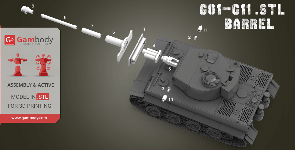
G10,G11 Main gun fixed joint left.stl 5 x 5 x 8 mm | 0.2 x 0.2 x 0.31 in
Size: 5 x 5 x 8 mm | 0.2 x 0.2 x 0.31 in
File size: 0.05 mb
Printing Time / Filament: 4 min / <1 m
G09 Brake device.stl 10 x 10 x 16 mm | 0.39 x 0.39 x 0.63 in
Size: 10 x 10 x 16 mm | 0.39 x 0.39 x 0.63 in
File size: 0.39 mb
Printing Time / Filament: 17 min / <1 m
G08 Barrel2.stl 5 x 5 x 53 mm | 0.2 x 0.2 x 2.09 in
Size: 5 x 5 x 53 mm | 0.2 x 0.2 x 2.09 in
File size: 0.19 mb
Printing Time / Filament: 28 min / <1 m
G07 Barrel1.stl 7 x 7 x 27 mm | 0.28 x 0.28 x 1.06 in
Size: 7 x 7 x 27 mm | 0.28 x 0.28 x 1.06 in
File size: 0.05 mb
Printing Time / Filament: 22 min / <1 m
G06 Main gun substrate1.stl 46 x 16 x 29 mm | 1.81 x 0.63 x 1.14 in
Size: 46 x 16 x 29 mm | 1.81 x 0.63 x 1.14 in
File size: 0.12 mb
Printing Time / Filament: 46 min / <1 m
G05 Loading device.stl 9 x 23 x 7 mm | 0.35 x 0.91 x 0.28 in
Size: 9 x 23 x 7 mm | 0.35 x 0.91 x 0.28 in
File size: 0.07 mb
Printing Time / Filament: 13 min / <1 m
G04 Main gun joints.stl 17 x 9 x 23 mm | 0.67 x 0.35 x 0.91 in
Size: 17 x 9 x 23 mm | 0.67 x 0.35 x 0.91 in
File size: 0.17 mb
Printing Time / Filament: 24 min / <1 m
G03 Trunnion right.stl 5 x 3 x 5 mm | 0.2 x 0.12 x 0.2 in
Size: 5 x 3 x 5 mm | 0.2 x 0.12 x 0.2 in
File size: 0.12 mb
Printing Time / Filament: 1 min / <1 m
G02 Trunnion left.stl 5 x 3 x 5 mm | 0.2 x 0.12 x 0.2 in
Size: 5 x 3 x 5 mm | 0.2 x 0.12 x 0.2 in
File size: 0.12 mb
Printing Time / Filament: 1 min / <1 m
G01 Main gun substrate2.stl 46 x 16 x 7 mm | 1.81 x 0.63 x 0.28 in
Size: 46 x 16 x 7 mm | 1.81 x 0.63 x 0.28 in
File size: 0.39 mb
Printing Time / Filament: 25 min / <1 m
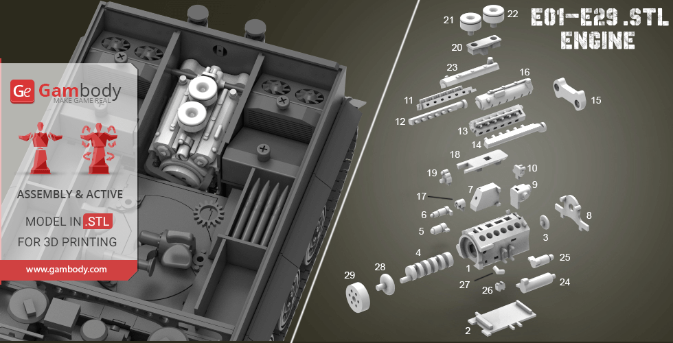
E29 Front flywheel cover.stl 14 x 14 x 5 mm | 0.55 x 0.55 x 0.2 in
Size: 14 x 14 x 5 mm | 0.55 x 0.55 x 0.2 in
File size: 0.09 mb
Printing Time / Filament: 6 min / <1 m
E28 Front flywheel.stl 11 x 11 x 7 mm | 0.43 x 0.43 x 0.28 in
Size: 11 x 11 x 7 mm | 0.43 x 0.43 x 0.28 in
File size: 0.21 mb
Printing Time / Filament: 5 min / <1 m
E27 Oil filter.stl 5 x 4 x 5 mm | 0.2 x 0.16 x 0.2 in
Size: 5 x 4 x 5 mm | 0.2 x 0.16 x 0.2 in
File size: 0.10 mb
Printing Time / Filament: 1 min / <1 m
E26 Fuel pump.stl 5 x 4 x 4 mm | 0.2 x 0.16 x 0.16 in
Size: 5 x 4 x 4 mm | 0.2 x 0.16 x 0.16 in
File size: 0.01 mb
Printing Time / Filament: 2 min / <1 m
E25 generator.stl 7 x 5 x 12 mm | 0.28 x 0.2 x 0.47 in
Size: 7 x 5 x 12 mm | 0.28 x 0.2 x 0.47 in
File size: 0.16 mb
Printing Time / Filament: 5 min / <1 m
E24 Oil cooler.stl 8 x 7 x 19 mm | 0.31 x 0.28 x 0.75 in
Size: 8 x 7 x 19 mm | 0.31 x 0.28 x 0.75 in
File size: 0.09 mb
Printing Time / Filament: 10 min / <1 m
E23 Engine Ignition Set Cover left.stl 7 x 8 x 30 mm | 0.28 x 0.31 x 1.18 in
Size: 7 x 8 x 30 mm | 0.28 x 0.31 x 1.18 in
File size: 0.31 mb
Printing Time / Filament: 28 min / <1 m
E21,E22 Air intake cover.stl 10 x 10 x 9 mm | 0.39 x 0.39 x 0.35 in
Size: 10 x 10 x 9 mm | 0.39 x 0.39 x 0.35 in
File size: 0.57 mb
Printing Time / Filament: 7 min / <1 m
E20 air filter.stl 6 x 17 x 7 mm | 0.24 x 0.67 x 0.28 in
Size: 6 x 17 x 7 mm | 0.24 x 0.67 x 0.28 in
File size: 0.14 mb
Printing Time / Filament: 7 min / <1 m
E19 After connecting the drive.stl 5 x 8 x 5 mm | 0.2 x 0.31 x 0.2 in
Size: 5 x 8 x 5 mm | 0.2 x 0.31 x 0.2 in
File size: 0.07 mb
Printing Time / Filament: 3 min / <1 m
E18 Upper cover.stl 8 x 26 x 5 mm | 0.31 x 1.02 x 0.2 in
Size: 8 x 26 x 5 mm | 0.31 x 1.02 x 0.2 in
File size: 0.02 mb
Printing Time / Filament: 7 min / <1 m
E17 Connector.stl 4 x 6 x 4 mm | 0.16 x 0.24 x 0.16 in
Size: 4 x 6 x 4 mm | 0.16 x 0.24 x 0.16 in
File size: 0.18 mb
Printing Time / Filament: 3 min / <1 m
E16 Engine Ignition Set Cover right.stl 7 x 8 x 30 mm | 0.28 x 0.31 x 1.18 in
Size: 7 x 8 x 30 mm | 0.28 x 0.31 x 1.18 in
File size: 0.26 mb
Printing Time / Filament: 27 min / <1 m
E15 The air area behind the engine.stl 28 x 12 x 5 mm | 1.1 x 0.47 x 0.2 in
Size: 28 x 12 x 5 mm | 1.1 x 0.47 x 0.2 in
File size: 0.05 mb
Printing Time / Filament: 10 min / <1 m
E14 Exhaust pipe right.stl 6 x 5 x 35 mm | 0.24 x 0.2 x 1.38 in
Size: 6 x 5 x 35 mm | 0.24 x 0.2 x 1.38 in
File size: 0.06 mb
Printing Time / Filament: 15 min / <1 m
E13 Engine ignition group right.stl 7 x 7 x 33 mm | 0.28 x 0.28 x 1.3 in
Size: 7 x 7 x 33 mm | 0.28 x 0.28 x 1.3 in
File size: 0.28 mb
Printing Time / Filament: 28 min / <1 m
E12 Left exhaust pipe.stl 6 x 6 x 35 mm | 0.24 x 0.24 x 1.38 in
Size: 6 x 6 x 35 mm | 0.24 x 0.24 x 1.38 in
File size: 0.12 mb
Printing Time / Filament: 16 min / <1 m
E11 Engine ignition group left.stl 7 x 7 x 33 mm | 0.28 x 0.28 x 1.3 in
Size: 7 x 7 x 33 mm | 0.28 x 0.28 x 1.3 in
File size: 0.28 mb
Printing Time / Filament: 29 min / <1 m
E10 Magnetic motor.stl 7 x 7 x 4 mm | 0.28 x 0.28 x 0.16 in
Size: 7 x 7 x 4 mm | 0.28 x 0.28 x 0.16 in
File size: 0.03 mb
Printing Time / Filament: 3 min / <1 m
E09 Generator fan.stl 10 x 10 x 9 mm | 0.39 x 0.39 x 0.35 in
Size: 10 x 10 x 9 mm | 0.39 x 0.39 x 0.35 in
File size: 0.27 mb
Printing Time / Filament: 8 min / <1 m
E08 Engine back cover.stl 27 x 16 x 3 mm | 1.06 x 0.63 x 0.12 in
Size: 27 x 16 x 3 mm | 1.06 x 0.63 x 0.12 in
File size: 0.04 mb
Printing Time / Filament: 5 min / <1 m
E07 Fuel tank.stl 7 x 10 x 14 mm | 0.28 x 0.39 x 0.55 in
Size: 7 x 10 x 14 mm | 0.28 x 0.39 x 0.55 in
File size: 0.16 mb
Printing Time / Filament: 16 min / <1 m
E06 Inertia starter.stl 6 x 4 x 11 mm | 0.24 x 0.16 x 0.43 in
Size: 6 x 4 x 11 mm | 0.24 x 0.16 x 0.43 in
File size: 0.07 mb
Printing Time / Filament: 3 min / <1 m
E05 Electric starter.stl 7 x 5 x 9 mm | 0.28 x 0.2 x 0.35 in
Size: 7 x 5 x 9 mm | 0.28 x 0.2 x 0.35 in
File size: 0.22 mb
Printing Time / Filament: 4 min / <1 m
E04 Cam.stl 7 x 7 x 30 mm | 0.28 x 0.28 x 1.18 in
Size: 7 x 7 x 30 mm | 0.28 x 0.28 x 1.18 in
File size: 0.09 mb
Printing Time / Filament: 25 min / <1 m
E03 Rear flywheel.stl 7 x 7 x 3 mm | 0.28 x 0.28 x 0.12 in
Size: 7 x 7 x 3 mm | 0.28 x 0.28 x 0.12 in
File size: 0.17 mb
Printing Time / Filament: 2 min / <1 m
E02 Lower cover.stl 23 x 31 x 3 mm | 0.91 x 1.22 x 0.12 in
Size: 23 x 31 x 3 mm | 0.91 x 1.22 x 0.12 in
File size: 0.01 mb
Printing Time / Filament: 12 min / <1 m
E01 Engine cavity.stl 23 x 31 x 17 mm | 0.91 x 1.22 x 0.67 in
Size: 23 x 31 x 17 mm | 0.91 x 1.22 x 0.67 in
File size: 0.35 mb
Printing Time / Filament: 1 h 33 min / 1 m
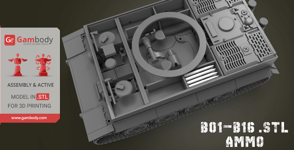
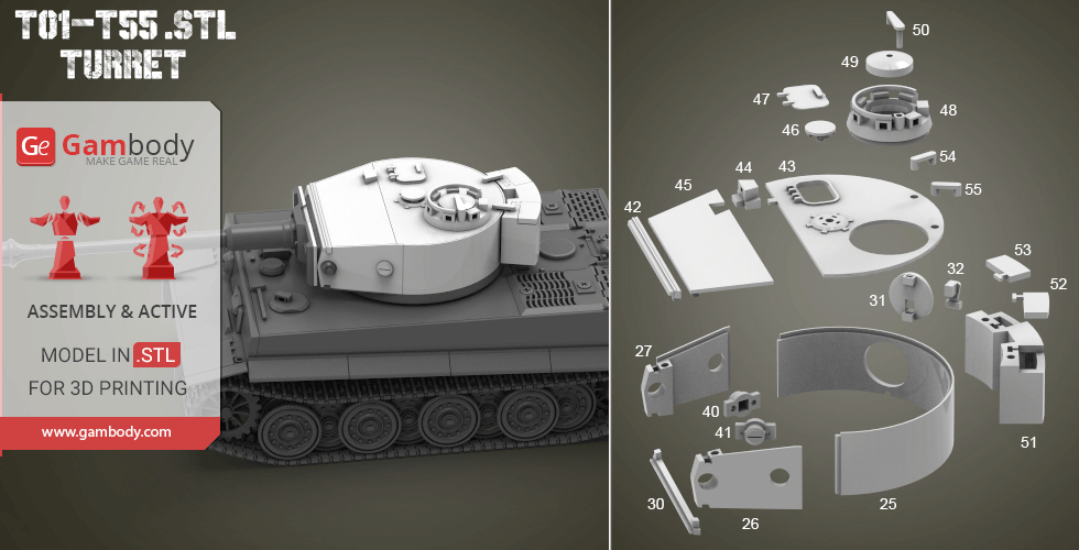
B1-B16 High explosive shells(TIGER have 92s, you can find where storage boxs _).stl 3 x 3 x 27 mm | 0.12 x 0.12 x 1.06 in
Size: 3 x 3 x 27 mm | 0.12 x 0.12 x 1.06 in
File size: 0.18 mb
Printing Time / Filament: 6 min / <1 m
Keychain (repaired).stl 29.68 x 29.69 x 2.42 mm | 1.17 x 1.17 x 0.1 in
Size: 29.68 x 29.69 x 2.42 mm | 1.17 x 1.17 x 0.1 in
File size: 0.37 mb
Printing Time / Filament: 23 min / <1 m
Tag (repaired).stl 150.15 x 18.16 x 4.59 mm | 5.91 x 0.71 x 0.18 in
Size: 150.15 x 18.16 x 4.59 mm | 5.91 x 0.71 x 0.18 in
File size: 1.78 mb
Printing Time / Filament: 1 h 18 min / 1 m
Models are regularly enhanced with updates and adjustments based on customer feedback. View update history
Description
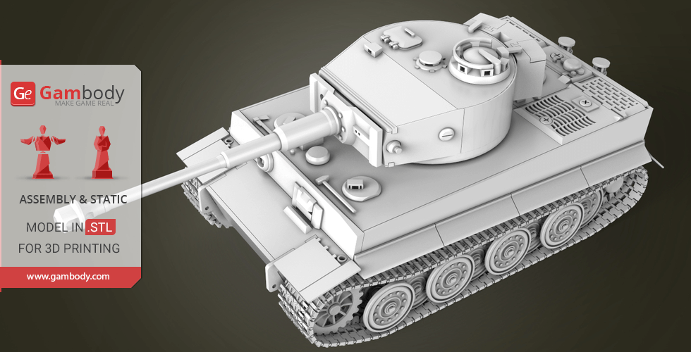
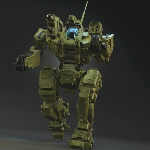
HISTORY OF THE TIGER I TANK
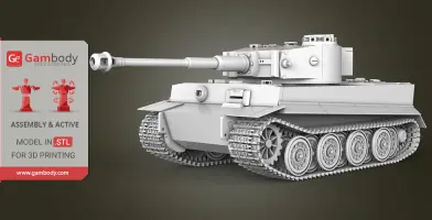
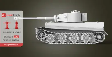
The heavy tank of the Second World War, the prototype of which was the VK4501 (H) tank, developed in 1942 by the firm "Henschel" under the direction of Erwin Aders. For the first time tanks "Tiger" went into battle on August 29, 1942, near the station Mga in Leningrad. Massively began to be used for the battle and capture of cities in February-March 1943, were used by the Wehrmacht and SS troops until the end of World War II. The total number of produced vehicles is 1354 units. The cost of producing one Tiger tank was twice expensive as any tank of that time. The inspiration for the creation this Tank was books and it was spent a lot of time to repeat all the details of the Tank as in real life.
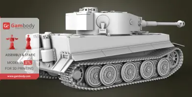
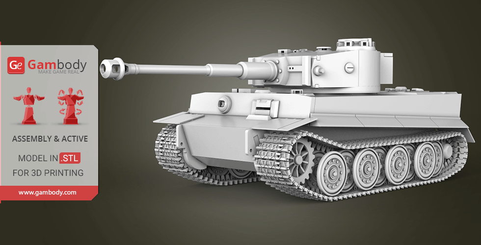
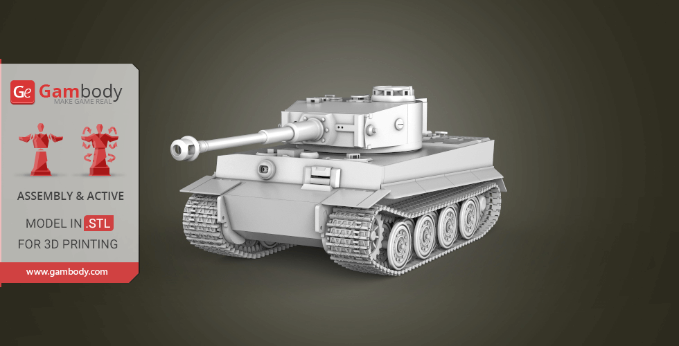
ABOUT THIS 3D MODEL KIT
The model is saved in STL files, a format supported by most 3D printers.
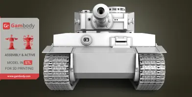
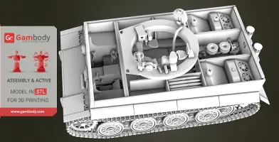
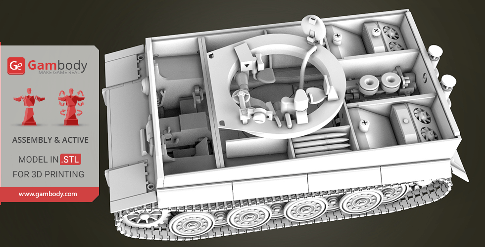
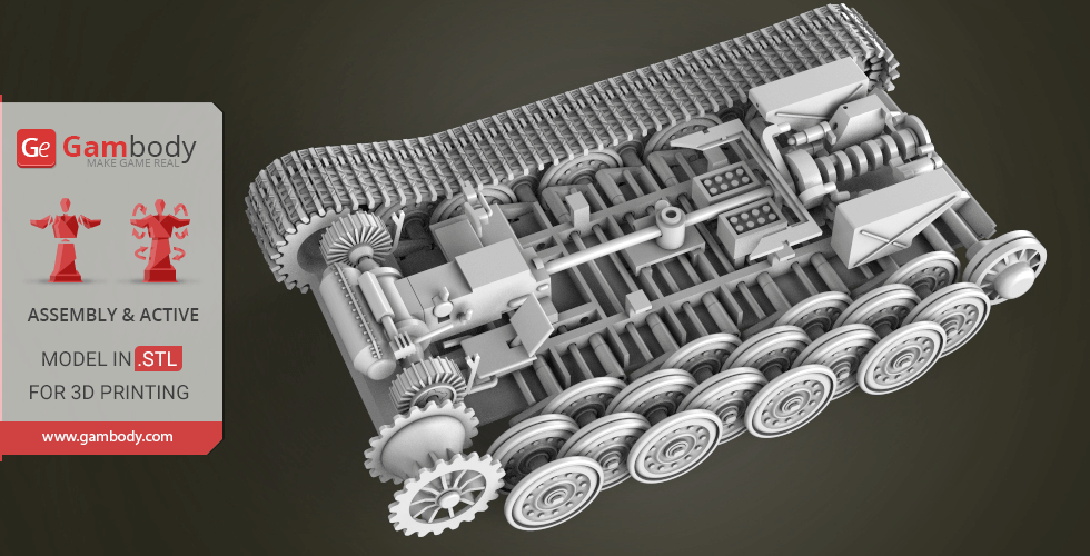
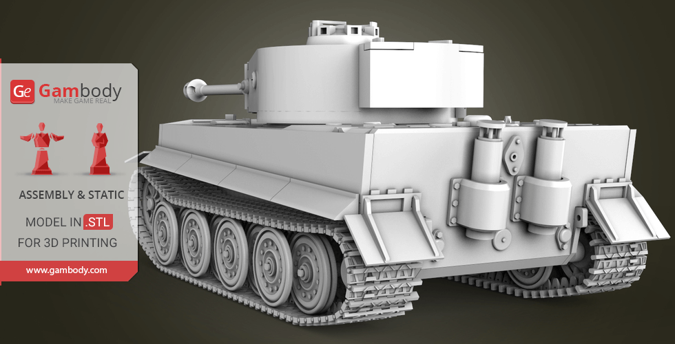
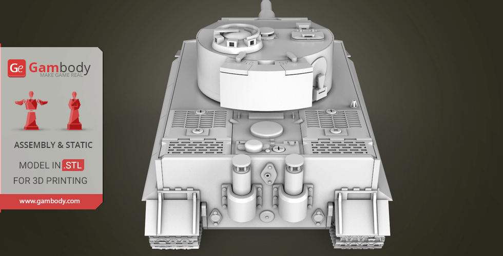
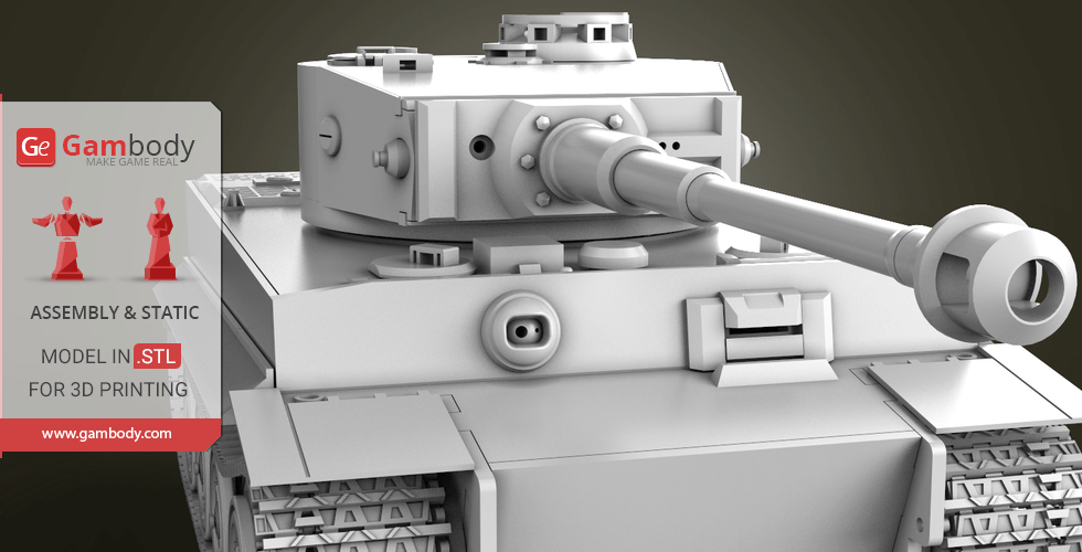
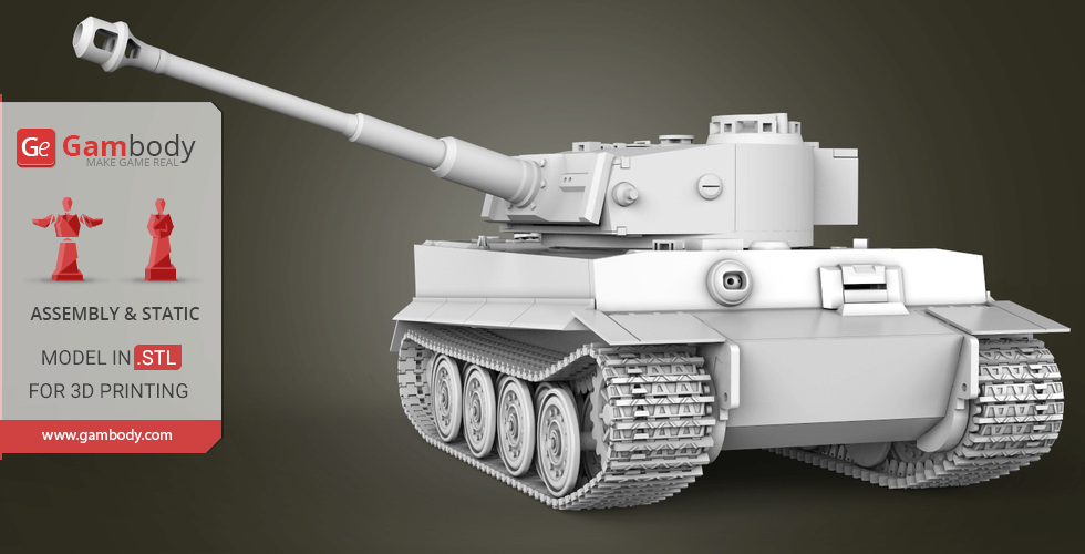
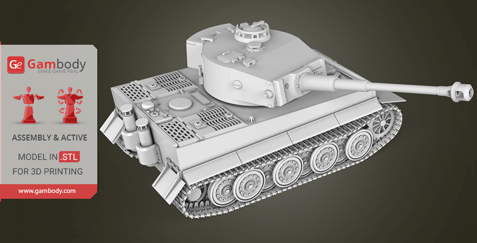
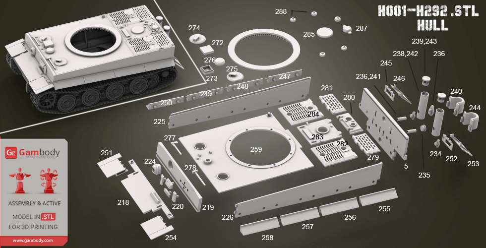
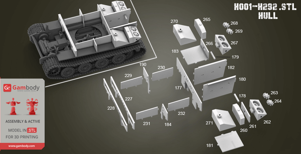
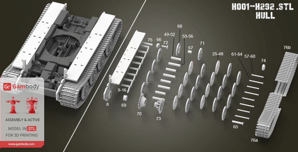
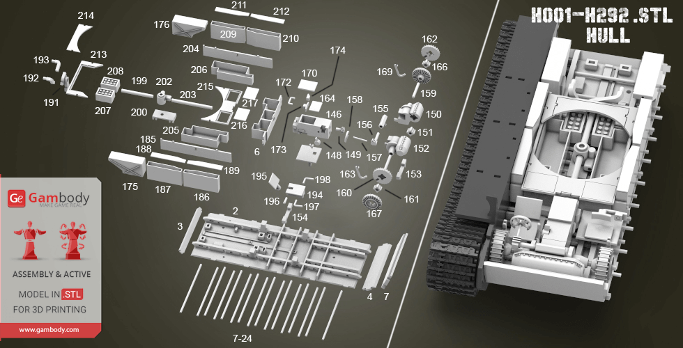
Features of this model: - Almost without glue when assembling the model; - Contains 249 stl files and 404 details; - Made as 1/35 scale; - All parts accurately repeats the parts of the prototype; - Ammo B01-B16 parts; - Barrel G01-G11 parts; - Engine E01-E29 parts; - Turret T01-T55 parts; - Hull H001-H292 parts; - All parts in this model are divided in a special way so that they will print with minimal use of support material;
All STL files for 3D printing have been checked in Netfabb and no errors were shown.
Note: Some parts of this model you need to print few times;
Before starting 3D printing the model, read the Printing Details for CURA 3.1.0 software.
This Tank contains 404 parts in 249 stl files. All small parts should be printed at 100% infill.
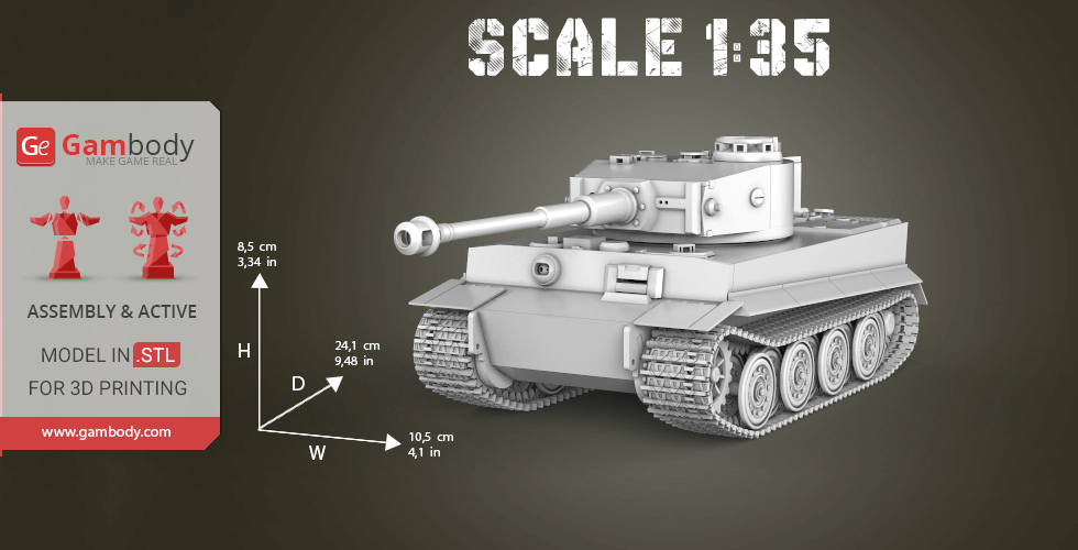
Scale: Its length in real life is 8435 mm. Model made as 1/35 scale.
Dimensions: - After being printed will stand: 85 mm tall, 105 mm wide, 241 mm deep; - Small parts should be printed at 100% infill to make them solid.
WHAT WILL YOU GET AFTER PURCHASE?
- STL files of Tiger I Tank for printing which consists of 249 stl files. - All parts accurately repeats the parts of the prototype; - Made in scale 1/35 of Its real size; - All parts are divided in such way that you will print them with the smallest amount of supports; - Detailed settings that we provide for Cura 3.1.0. for the best print; - Full technical support from the Gambody Support Team.
You can get Tiger I Tank Model for 3D Printing right now! Just click the green Buy button in the top-right corner of the model’s page. You can pay with PayPal or your credit card.
Quick rating from the old site version (no comment)
Reviewed on April 04, 2025
Overall experience
Level of detail in the model
4
Model cut quality and assembly guide
4
Clarity and accuracy of the model page
4
User ID: 88848
Verified purchase
Quick rating from the old site version (no comment)
Reviewed on November 21, 2024
Overall experience
Level of detail in the model
4
Model cut quality and assembly guide
4
Clarity and accuracy of the model page
4
User ID: 73067
This feedback is from a user who hasn't purchased this model
Quick rating from the old site version (no comment)
Reviewed on March 20, 2022
Overall experience
Level of detail in the model
5
Model cut quality and assembly guide
5
Clarity and accuracy of the model page
5
Blondytw
This feedback is from a user who hasn't purchased this model
Quick rating from the old site version (no comment)
Reviewed on October 23, 2019
Overall experience
Level of detail in the model
5
Model cut quality and assembly guide
5
Clarity and accuracy of the model page
5
User ID: 14948
Verified purchase
Quick rating from the old site version (no comment)
Reviewed on July 27, 2019
Overall experience
Level of detail in the model
5
Model cut quality and assembly guide
5
Clarity and accuracy of the model page
5
User ID: 13416
Verified purchase
Quick rating from the old site version (no comment)
Reviewed on May 11, 2019
Overall experience
Level of detail in the model
5
Model cut quality and assembly guide
5
Clarity and accuracy of the model page
5
User ID: 8507
This feedback is from a user who hasn't purchased this model
Quick rating from the old site version (no comment)
Reviewed on October 03, 2018
Overall experience
Level of detail in the model
5
Model cut quality and assembly guide
5
Clarity and accuracy of the model page
5
User ID: 3694
This feedback is from a user who hasn't purchased this model
Quick rating from the old site version (no comment)
Reviewed on April 30, 2018
Overall experience
Level of detail in the model
5
Model cut quality and assembly guide
5
Clarity and accuracy of the model page
5
kangkang
3D Artist (Author of this model)
Quick rating from the old site version (no comment)
Reviewed in China on January 31, 2018
Overall experience
Level of detail in the model
5
Model cut quality and assembly guide
5
Clarity and accuracy of the model page
5
D.S.
This feedback is from a user who hasn't purchased this model
Quick rating from the old site version (no comment)
Reviewed on January 30, 2018
Overall experience
Level of detail in the model
5
Model cut quality and assembly guide
5
Clarity and accuracy of the model page
5
Aleksandr I.
This feedback is from a user who hasn't purchased this model
Quick rating from the old site version (no comment)
Reviewed in United Kingdom of Great Britain and Northern Ireland on January 30, 2018
Overall experience
Level of detail in the model
5
Model cut quality and assembly guide
5
Clarity and accuracy of the model page
5
Model rating
Overall experience
Level of detail in the model
Model cut quality and assembly guide
Clarity and accuracy of the model page
Enter for new line | Ctrl+Enter to submit text
Printing Details
Below you'll find detailed slicing settings for Bambu Studio 2.0+, Orca Slicer 2.0+, UltiMaker Cura 5.0+, PrusaSlicer 2.0+, Slic3r 1.3+, Simplify3D 5.0+ to help you get the best results when printing this model. These settings are optimized specifically for this 3D model, but please note they may need slight adjustments depending on your printer or filament. When in doubt, refer to your printer's user manual.
Important
To avoid printing issues and achieve the best quality, we highly recommend applying the following settings:
Bambu Studio 2.0+
Settings name
Option
Quality Tab
Layer height
Layer Height
0.12 - 0.20 mm
For better quality use 0.12 mm layer height, for fast printing use 0.2 mm layer height. For pins and the Ge connectors, use 0.2 layer height.
First layer height
0.20 - 0.28 mm
120-150% of your Layer Height
Line width
Default:
0.42 mm
Initial Layer
0.50 - 0.60 mm
Outer wall
0.40 mm
Inner wall
0.45 mm
Top surface
0.45 mm
Sparse infill
0.45 mm
Internal solid infill
0.42 mm
Support
0.42 mm
Seam
Seam position
Aligned
But you can paint the seam if you want.
Smart scarf seam application
✔
Scarf application angle threshold
155.0 °
Scarf steps
10.0
Scarf joint for inner walls
✔
Role-based wipe speed
✔
Precision
Slice gap closing radius
0.0490 mm
Resolution
0.0120 mm
Arc fitting
✔
X-Y hole compensation
0.010 - 0.050 mm
You have to calibrate this parameter
X-Y contour compensation
0.010 - 0.050 mm
You have to calibrate this parameter
Elephant foot compensation
0.10 - 0.20 mm
You have to calibrate this parameter
Wall generator
Wall generator
Classic
Wall transitioning threshold angle
10.0 °
Wall transitioning filter margin
25.0 %
Wall transition length
100.0 %
Minimum wall width
85.0 %
Minimum feature size
25.0 %
Advanced
Order of walls
inner/outer
Bridge flow
0.85
Only one wall on top surfaces
Top surfaces
Smooth speed discontinuity area
✔
Smooth coefficient
80.0
Strength
Walls
Wall loops
2 - 3
For pins and power elements of the structure, such as the vehicle frame, use 3 loop
Detect thin wall
Disabled for vehicles and enabled for characters
Top/bottom shells
Top surface pattern
Monotonic
Top shell layers
5
For 0,2 Layer Height
Top shell thickness
1.00 mm
Top paint penetration layers
5
Bottom surface pattern
Monotonic
Bottom shell layers
5
Bottom shell thickness
1.00 mm
Bottom paint penetration layers
5
Internal solid infill pattern
Rectilinear
Sparse infill
Sparse infill density
6.0 %
Sparse infill pattern
Triangles
Length of sparse infill anchor
400.0 %
Maximum length of sparse infill anchor
20.0 mm
Advanced
Infill/Wall overlap
15.0 - 25.0 %
Infill direction
45.0 °
Bridge direction
0.0 °
Minimum sparse infill threshold
10.0 mm²
Detect narrow internal solid infill
✔
Ensure vertical shell thickness
Enabled
Detect floating vertical shells
✔
Speed
The parameters in this tab vary greatly, it all depends on the quality of your printer. For example, if you have a classic Ender3, stick to the minimum parameters, but if you have a newer printer, for example Anycubic cobra 3 v2, you can select the maximum recommended values
Initial layer speed
Initial layer
15.0 - 45.0 mm/sec
Initial layer infill
35.0 - 75.0 mm/sec
Other layers speed
Outer wall
30.0 - 150.0 mm/sec
Inner wall
30.0 - 250.0 mm/sec
Small perimeters
50.0 %
Small perimeter threshold
0.1 mm
Sparse infill
50.0 - 250.0 mm/sec
Internal solid infill
50.0 - 200.0 mm/sec
Vertical shell speed
80.0 %
Top surface
25.0 - 150.0 mm/sec
Slow down for overhangs
✔
Overhang speed
Overhang speed 10%
0.0 mm/sec
Overhang speed 25%
40.0 mm/sec
Overhang speed 50%
20.0 mm/sec
Overhang speed 75%
10.0 mm/sec
Overhang speed 100%
10.0 mm/sec
Bridge
20.0 - 40.0 mm/sec
Gap infill
30.0 - 150.0 mm/sec
Support
30.0 - 100.0 mm/sec
Support interface
30.0 - 60.0 mm/sec
Travel speed
Travel
80.0 - 350.0 mm/sec
Acceleration
Settings for advanced users, change these parameters only if you have sufficient 3D printing expertise
Normal printing
2,500.0 - 4,000.0 mm/sec²
Travel
2,000.0 - 7,000.0 mm/sec²
Initial layer travel
700.0 - 5,000.0 mm/sec²
Initial layer
300.0 - 500.0 mm/sec²
Outer wall
500.0 - 3,000.0 mm/sec²
Inner wall
500.0 - 4,000.0 mm/sec²
Top surface
500.0 - 2,500.0 mm/sec²
Sparse infill
100.0 - 100.0 %
Support
Support
Enable support
✔
Enable this parameter if your model requires supports
Type
Tree (auto)
Style
Default
Threshold angle
10.0 - 60.0 °
We also recommend placing and removing supports manually in some places using special button
Remove small overhangs
✔
Raft
Raft layers
0 layers
Advanced
Initial layer density
90.0 %
Initial layer expansion
-1.0 mm
Support wall loops
-1 - 2
1-2 loops for more thick support
Top Z distance
0.20 - 0.25 mm
Top Z distance = 1-1.3 layer Height. If the supports are hard to remove, try increasing this setting by 0.1-0,4 mm
Bottom Z distance
Bottom Z distance = 1-1.3 layer Height. If the supports are hard to remove, try increasing this setting by 0.1-0,4 mm
Base pattern
Rectilinear
Base pattern spacing
2.50 mm
Pattern angle
0.0 °
Top interface layers
2 - 3 layers
Interface pattern
Concentric
Top interface spacing
0.00 - 0.50 mm
You have to calibrate this parameter which one is better for your filament
Normal Support expansion
0.00 mm
Support/object xy distance
0.35 - 0.80 mm
Increase this parameter if the supports are hard to remove from walls
Support/object first layer gap
0.35 mm
Max bridge length (only for tree supports)
1.0 mm
Independent support layer height
✔
Tree Support (only for tree supports)
Branch distance
5.0 mm
Branch diameter
2.0 mm
Branch angle
45.0 °
Branch diameter angle
5.0 °
Others
Bed adhesion
Skirt loops
0
Skirt height
1 layers
For PLA and PETG filament types
Brim type
Outer and inner brim
Brim width
5.00 mm
5-8 mm is optional for small prints that have bad adhesion to the build plate
Brim-object gap
0.01 - 0.12 mm
Prime tower
Enable
✔
Skip points
✔
Width
35.0 mm
Max speed
90.0 mm/sec
Brim width
3.0 mm
Infill gap
150.0 %
Rib wall
✔
Rib width
8.0 mm
Fillet wall
✔
Flush options
Flush into objects support
✔
Special mode
Slicing Mode
Regular
Print sequence
By layer
Timelapse
Traditional
G-code output
Reduce infill retraction
✔
Filament settings
Filament
Type
PLA
Filament ramming length
10.0 mm
Filament prime volume
45.0 mm³
Diameter
1.75 mm
Flow ratio
0.90 - 1.10
You have to calibrate this parameter
Shrinkage
100.0 %
Velocity Adaptation Factor
1.0
Softening temperature
45.0 - 80.0 ⁰C
Read the description on your filament roll
Travel time after ramming
0.0 sec
Precooling target temperature
0.0 ⁰C
Recommended nozzle temperature
190.0 - 270.0 ⁰C
Read the description on your filament roll and increase this parameter for fast printers
Print temperature
Cool Plate SuperTack
45.0 - 45.0 ⁰C
Cool Plate
35.0 - 35.0 ⁰C
Engineering Plate
0.0 - 0.0 ⁰C
Smooth PEI Plate / High
65.0 - 65.0 ⁰C
Temp Plate
65.0 - 65.0 ⁰C
Textured PEl Plate
65.0 - 65.0 ⁰C
Nozzle
220.0 - 270,200.0 ⁰C
Read the description on your filament roll and increase this parameter for fast printers
Volumetric speed limitation
Max volumetric speed
12.0 mm/sec
Ramming volumetric speed
-1.0 mm/sec
Filament scarf seam settings
Scarf start height
10.0 %
Scarf length
10.0 mm
Cooling
Cooling for specific layer
1 layers
No cooling for the first
1 layers
Part cooling fan
Min fan speed threshold
Fan speed
60.0 %
Layer time
90.0 sec
Max fan speed threshold
Fan speed
80.0 %
Layer time
8.0 sec
Keep fan always on
✔
Slow printing down for better layer cooling
✔
Min print speed
10.0 mm/sec
Force cooling for overhangs and bridges
✔
Cooling overhang threshold
50.0 %
Overhang threshold for participating cooling
100.0 %
Fan speed for overhangs
100.0 %
Pre start fan time
0.0 sec
Auxiliary part cooling fan
Fan speed
70.0 %
Printer Settings Tab
Motion ability
Jerk limitation
Maximum jerk X
7.0 mm/sec
Maximum jerk Y
7.0 mm/sec
Maximum jerk Z
0.4 mm/sec
Maximum jerk E
5.0 mm/sec
Extruder
Basic information
Type
Direct drive extruder
Nozzle diameter
0.40 mm
Nozzle volume
0.0 mm³
Layer height limits
Min
0.08 mm
Max
0.35 mm
Retraction
Length
0.70 mm
Z hop when retract
0.3 mm
Z hop lower boundary
0.0 mm
Z Hop Type
Normal
Retraction Speed
30.0 mm/sec
Deretraction Speed
30.0 mm/sec
Travel distance threshold
1.0 mm
Retract when change layer
✔
Wipe while retracting
✔
Wipe Distance
2.0 mm
Retract amount before wipe
70.0 %
Orca Slicer 2.0+
Settings name
Option
Quality Tab
Layer height
Layer Height
0.12 - 0.20 mm
For better quality use 0.12 mm layer height, for fast printing use 0.2 mm layer height. For pins and the Ge connectors, use 0.2 layer height.
For pins and power elements of the structure, such as the vehicle frame, use 3 loop
Detect thin walls
Disabled for vehicles and ships, enabled for characters
Top/bottom shells
Top shell layers
5 layers
For 0,2 Layer Height
Top shell thickness
1.00 mm
Top surface density
100 %
Top surface pattern
Monotonic line
Bottom shell layers
5 layers
For 0,2 Layer Height
Bottom shell thickness
1.00 mm
Bottom surface density
100.0 %
Bottom surface pattern
Monotonic
Top/Bottom solid infill/wall overlap
25.0 %
Infill
Sparse infill density
5.0 %
Fill Multiline
1.00
Sparse infill pattern
Triangles
Sparse infill direction
45.0 °
Maximum length of the infill anchor
20.0 mm
Sparse infill anchor length
400.0 %
Internal solid infill pattern
Monotonic
Solid infill direction
45.0 °
Apply gap fill
Nowhere
Filter out tiny gaps
0.00 mm
Infill/wall overlap
10.0 - 25.0 %
Advanced
External bridge infill direction
0.0 °
Internal bridge infill direction
0.0 °
Minimum sparse infill threshold
15.0 mm²
Detect narrow internal solid infill
✔
Ensure vertical shell thickness
All
Speed
The parameters in this tab vary greatly, it all depends on the quality of your printer. For example, if you have a classic Ender3, stick to the minimum parameters, but if you have a newer printer, for example, Anycubic Kobra 3 Or Bambulab A1, you can select the maximum recommended values.
First layer speed
First layer
15.0 - 45.0 mm/sec
First layer infill
35.0 - 75.0 mm/sec
Initial layer travel speed
50.0 %
Number of slow layers
2 layers
Other layers speed
Outer wall
30.0 - 150.0 mm/sec
Inner wall
30.0 - 250.0 mm/sec
Small perimeters
50.0 %
Small perimeter threshold
0.1 mm
Sparse infill
50.0 - 250.0 mm/sec
Internal solid infill
50.0 - 250.0 mm/sec
Top surface
30.0 - 150.0 mm/sec
Gap infill
30.0 - 200.0 mm/sec
Slow down by height
✘
Overhang speed
Slow down for overhangs
✔
Slow down for curled perimeters
✔
Overhang speed 10%, 25%
0.0 mm/sec
Overhang speed 25%, 50%
50.0 mm/sec
Overhang speed 50%, 75%
30.0 mm/sec
Overhang speed 75%, 100%
10.0 mm/sec
Bridge external
20.0 - 40.0 mm/sec
Bridge internal
30.0 mm/sec
Travel speed
Travel
100.0 - 300.0 mm/sec
Acceleration
Settings for advanced users, change these parameters only if you have sufficient 3D printing expertise
Normal printing
5,000.0 mm/sec²
Outer wall
3,000.0 mm/sec²
Inner wall
3,000.0 mm/sec²
Bridge
50.0 %
Sparse infill
100.0 %
Internal solid infill
100.0 %
First layer
300.0 mm/sec²
Top surface
3,000.0 mm/sec²
Travel
5,000.0 mm/sec²
accel to decel
50.0 %
Jerk(XY)
Default
9.0 mm/sec
Outer wall
7.0 mm/sec
Inner wall
7.0 mm/sec
Infill
10.0 mm/sec
Top surface
7.0 mm/sec
First layer
9.0 mm/sec
Travel
12.0 mm/sec
Support
Support
Enable support
✔
Enable this parameter if your model requires supports
Type
Tree (auto)
Style
Default
Threshold angle
60.0 °
We also recommend placing and removing supports manually in some places using special button
Threshold overlap
50.0 %
First layer density
90.0 %
First layer expansion
2.0 mm
Remove small overhangs
✔
Raft
Raft layers
0 layers
Advanced
Top Z distance
0.20 - 0.25 mm
Top Z distance = 1-1.3 layer Height. If the supports are hard to remove, try increasing this setting by 0.1-0,4 mm
Bottom Z distance
0.20 - 0.25 mm
Bottom Z distance = 1-1.3 layer Height. If the supports are hard to remove, try increasing this setting by 0.1-0,4 mm
Support wall loops
0
Base pattern
Rectilinear
Base pattern spacing
2.50 mm
Pattern angle
0.0 °
Top interface layers
2 layers
Bottom interface layers
2 layers
Interface pattern
Rectilinear
Top interface spacing
0.00 mm
Bottom interface spacing
0.00 mm
Normal Support expansion
0.00 mm
Support/object xy distance
0.40 mm
Increase this parameter if the supports are hard to remove from walls
Support/object first layer gap
0.35 mm
Independent support layer height
✔
Tree Support (only for tree supports)
Tip Diameter
0.80 mm
Tree support branch distance
1.00 mm
Branch Density
30.0 %
Tree support branch diameter
2.0 mm
Branch Diameter Angle
5.0 °
Tree support branch angle
40.0 °
Preferred Branch
25.0 °
Others
Skirt
Skirt loops
0
Skirt type
Combined
Skirt minimum extrusion length
0.00 mm
Skirt distance
2.00 mm
Skirt start point
-135.0 °
Skirt speed
50.0 mm/sec
Skirt height
1.0 layers
For PLA and PETG filament types
Draft shield
Disabled
Brim
Brim type
Outer and inner brim
Brim width
5.0 mm
5-8 mm is optional for small prints that have bad adhesion to the build plate
Brim-object gap
0.01 - 0.12 mm
Special mode
Slicing Mode
Regular
Print sequence
By layer
Intra-layer order
Default
G-code output
Label objects
✔
Filename format
{input _filename_ base}_{print_time}.gcode
Filament Tab
Filament
Basic information
Type
PLA
Shrinkage (XY)
100.0 %
Shrinkage (Z)
100.0 %
Softening temperature
60.0 ⁰C
Read the description on your filament roll
Idle temperature
0.0 ⁰C
Recommended nozzle temperature
190.0 - 270.0 ⁰C
Read the description on your filament roll and increase this parameter for fast printers
Flow ratio and Pressure Advance
Flow ratio
0.90 - 1.10
You have to calibrate this parameter
Print chamber temperature
Chamber temperature
0.0 ⁰C
Print temperature
Nozzle
Read the description on your filament roll and increase this parameter for fast printers
First layer
190.0 - 270.0 ⁰C
Other layers
190.0 - 270.0 ⁰C
Bed temperature
Read the description on your filament roll
Cool Plate (SuperTack)
First layer
45.0 ⁰C
Other layers
45.0 ⁰C
Cool Plate
First layer
35.0 ⁰C
Other layers
35.0 ⁰C
Textured Cool Plate
First layer
40.0 ⁰C
Other layers
40.0 ⁰C
Engineering Plate
First layer
0.0 ⁰C
Other layers
0.0 ⁰C
Smooth PEI Plate / High Temp Plate
First layer
55.0 ⁰C
Other layers
55.0 ⁰C
Textured PEI Plate
First layer
55.0 ⁰C
Other layers
55.0 ⁰C
Volumetric speed limitation
Max volumetric speed
21.0 mm/sec
Cooling
Cooling for specific layer
No cooling for the first
1.0 layers
Full fan speed at layer
3.0 layers
Part cooling fan
Min fan speed threshold
Fan speed
70.0 %
Layer time
80.0 sec
Max fan speed threshold
Fan speed
80.0 %
Layer time
6.0 sec
Keep fan always on
✔
Slow printing down for better layer cooling
✔
Min print speed
9 mm/sec
Force cooling for overhangs and bridges
✔
Overhang cooling activation threshold
50.0 %
Overhangs and external bridges fan speed
100.0 %
Internal bridges fan speed
-1.0 %
Support interface fan speed
-1.0 %
Ironing fan speed
-1.0 %
Auxiliary part cooling fan
Fan speed
70.0 %
Exhaust fan
During print
69.9 %
Complete print
70.0 %
Printer Settings Tab
Basic information
This field is filled in according to your printer specifications when you add it to the slicer.
Machine G-code
You can add custom G-code here for the start and end of the print. However, be careful - this is for advanced users only!
Retraction Length: For direct-drive setups use 0.5 mm to 2.5 mm; for Bowden extruders use 5 to 7 mm
Extra length on restart
0.00 mm
Retraction speed
40 mm/sec
Deretraction speed
40.0 mm/sec
This is how fast the filament is pulled back—40-60 mm/s for direct drive and 30-50 mm/s for Bowden setups.
Travel distance threshold
1.00 mm
Retract on layer change
✔
Wipe while retracting
✔
Wipe distance
2.00 mm
Retract amount before wipe
70.0 %
Z-Hop
On surfaces
All surfaces
Z-hop type
Auto
Z-hop height
0.30 mm
You have to calibrate this parameter: Reduce it until the printer starts to hit the parts with the nozzle during printing, then increase it by 0.2.
Traveling angle
3.0 °
Only lift Z above
0.00 mm
Only lift Z below
0.00 mm
Retraction when switching material
Length
1.00 mm
Extra length on restart
0.00 mm
UltiMaker Cura 5.0+
Settings name
Option
Quality
Layer Height
0.12 - 0.20 mm
For better quality use 0.12 mm layer height, for fast printing use 0.2 mm layer height. For pins and the Ge connectors, use 0.2 layer height.
Initial Layer Height
0.20 mm
120-150% of your Layer Height
Line Width
0.42 mm
Wall Line Width
0.40 mm
Outer Wall Line Width
0.40 mm
Inner Wall(s) Line Width
0.42 mm
Top/Bottom Line Width
0.44 mm
Infill Line Width
0.40 mm
Skirt/Brim Line Width
0.42 mm
Initial Layer Line Width
0.5 %
Walls
Wall Thickness
0.80 mm
Wall Line Count
2
To increase the strength of the print parts, use wall line count: 3
Wall Transition Length
0.20 mm
Wall Distribution Count
1
Wall Transitioning Threshold Angle
10.0 °
Wall Transitioning Filter Margin
0.10 mm
Outer Wall Wipe Distance
0.00 mm
Optimize Wall Printing Order
✔
Wall Ordering
Inside to Outsize
Minimum Wall Line Width
0.34 mm
Minimum Even Wall Line Width
0.34 mm
Minimum Odd Wall Line Width
0.34 mm
Print Thin Walls
✔
Minimum Feature Size
0.10 mm
Minimum Thin Wall Line Width
0.34 mm
Horizontal Expansion
0.00 mm
Initial Layer Horizontal Expansion
0.00 mm
Hole horizontal expansion
0.00 mm
Z Seam Alignment
User Specified
Z Seam Position
Back
Z Seam X
0.0 mm
Z Seam Y
200.0 mm
Top/Bottom
Top Surface Skin Layers
0 layers
Bottom Surface Skin Layers
0 layers
Top/Bottom Thickness
1.00 mm
Top Thickness
1.00 mm
Bottom Thickness
1.00 mm
Initial Bottom Layers
4 - 5 layers
Top/Bottom Pattern
Lines
Bottom Pattern Initial Layer
Lines
Extra Skin Wall Count
1
Enable Ironing
✘
Infill
For pins and connectors use 50% Infill
Infill Density
5.0 - 30.0 %
Infill Line Distance
6.00 mm
Infill Pattern
Triangles
Infill X Offset
0.00 mm
Infill Y Offset
0.00 mm
Infill Line Multiplier
1
Infill Overlap Percentage
30.0 %
Infill Overlap
0.12 mm
Infill Wipe Distance
0.00 mm
Infill Layer Thickness
0.20 mm
Gradual Infill Steps
0
Minimum Infill Area
0.00 mm²
Skin Edge Support Thickness
0.00 mm
Skin Edge Support Layers
0
Extra Infill Lines To Support Skins
Walls and Lines
Material
These parameters are for standard PLA plastic. If you are using a different type of plastic, check the printing temperature recommended by the manufacturer. Also, read the description on your filament spool. For fast printers, add +30 °C to the current parameters.
Printing Temperature
210.0 ⁰C
Printing Temperature Initial Layer
210.0 ⁰C
Initial Printing Temperature
210.0 ⁰C
Final Printing Temperature
210.0 ⁰C
Build Plate Temperature
60.0 ⁰C
Build Plate Temperature Initial Layer
60.0 ⁰C
Scaling Factor Shrinkage Compensation
100.0 %
Horizontal Scaling Factor Shrinkage Compensation
100.0 %
Vertical Scaling Factor Shrinkage Compensation
100.0 %
Flow
98.0 - 102.0 %
Speed
The parameters in this tab vary greatly, it all depends on the quality of your printer. For example, if you have a classic Ender3, stick to the minimum parameters, but if you have a newer printer, for example Anycubic cobra 3 v3, you can select the maximum recommended values
Print Speed
60.0 - 160.0 mm/sec
Infill Speed
60.0 - 160.0 mm/sec
Wall Speed
30.0 - 90.0 mm/sec
Outer Wall Speed
30.0 - 90.0 mm/sec
Inner Wall Speed
40.0 - 80.0 mm/sec
Top/Bottom Speed
40.0 - 100.0 mm/sec
Travel Speed
100.0 - 250.0 mm/sec
Initial Layer Speed
15.0 - 30.0 mm/sec
Initial Layer Print Speed
15.0 - 30.0 mm/sec
Initial Layer Travel Speed
100.0 - 150.0 mm/sec
Skirt/Brim Speed
20.0 - 30.0 mm/sec
Number of Slower Layers
2.0 layers
Flow Equalization Ratio
100.0 %
Enable Acceleration Control
✔
Settings for advanced users, change these parameters only if you have sufficient 3D printing expertise.
Print Acceleration
500.00 - 3,000.00 mm/sec²
Infill Acceleration
500.0 - 3,000.0 mm/sec²
Wall Acceleration
500.0 - 2,000.0 mm/sec²
Outer Wall Acceleration
500.0 - 2,000.0 mm/sec²
Inner Wall Acceleration
500.0 - 3,000.0 mm/sec²
Top/Bottom Acceleration
500.0 - 2,000.0 mm/sec²
Travel Acceleration
500.0 - 4,000.0 mm/sec²
Initial Layer Acceleration
500.0 - 1,000.0 mm/sec²
Initial Layer Print Acceleration
500.0 - 1,000.0 mm/sec²
Initial Layer Travel Acceleration
500.0 - 3,000.0 mm/sec²
Skirt/Brim Acceleration
500.0 - 2,500.0 mm/sec²
Travel
Enable Retraction
✔
Retraction Distance
0.8 mm
You need to calibrate this parameter using Gambody test models. These values are average values for a Direct Drive extruder; for a Bowden extruder, the values should be increased.
Retraction Speed
35.0 - 50.0 mm/sec
You need to calibrate this parameter using Gambody test models. These values are average values for a Direct Drive extruder; for a Bowden extruder, the values should be increased.
Retraction Retract Speed
40.0 mm/sec
Retraction Prime Speed
40.0 mm/sec
Retraction Extra Prime Amount
0.00 mm³
Retraction Minimum Travel
1.49 mm
Maximum Retraction Count
100
Minimum Extrusion Distance Window
2.00 - 3.00 mm
Combing Mode
All
Retract Before Outer Wall
✔
Layer Start X
0.00 mm
Layer Start Y
0.00 mm
Z Hop When Retracted
✔
Use this value other than 0 if your nozzle catches on the internal infill during travel moves. Try to keep this value as low as possible in height.
Cooling
Enable Print Cooling
✔
Fan Speed
100.0 %
Regular Fan Speed
100.0 %
Maximum Fan Speed
100.0 %
Regular/Maximum Fan Speed Threshold
10.0 sec
Initial Fan Speed
0.0 %
Regular Fan Speed at Height
0.5 mm
Regular Fan Speed at Layer
3 layers
Minimum Layer Time
5.0 sec
Minimum Speed
10.0 mm/sec
Cooling during extruder switch
Unchanged
Support
Generate Support
✔
Support Structure Normal
✔
Use normal supports to support large, straight surfaces (most mechanical or technical parts).
Support Z Seam Away from Model
Min Z Seam Distance from Model
0.80 mm
Support Placement
Everywhere
Support Overhang Angle
45.0 - 65.0 °
You have to calibrate this parameter according to the capabilities of your printer and your filament, using a Gambody test models.
Support Pattern
Zig Zag
Support Wall Line Count
0
Use 1 instead of 0 if your supports are thin and tall. They will be harder to remove, but much stronger.
Support Interface Wall Line Count
0
Support Roof Wall Line Count
0
Support Bottom Wall Line Count
0
Connect Support ZigZags
✔
Support Density
5.0 - 20.0 %
Support Line Distance
2.0 - 8.0 mm
Enable Support Brim
✔
Support Brim Width
4.0 mm
Support Brim Line Count
10
Support Z Distance
0.24 mm
Top Z distance = 1-1.3 layer Height. If the supports are hard to remove, try increasing this setting by 0.1-0,4 mm
Support Top Distance
0.24 mm
Support Bottom Distance
0.24 mm
Support X/Y Distance
0.80 mm
Increase this parameter if the supports are hard to remove from walls
Support Distance Priority
X/Y overrides Z
Support Stair Step Height
0.00 mm
Support Join Distance
2.00 mm
Support Horizontal Expansion
0.80 mm
Support Infill Layer Thickness
0.20 mm
Gradual Support Infill Steps
0
Minimum Support Area
2.0 mm²
Enable Support Interface
✔
Enable Support Roof
✔
Enable Support Floor
✔
Support Interface Thickness
0.40 mm
Support Roof Thickness
0.40 mm
Support Floor Thickness
0.40 mm
Support Interface Density
33.33 - 33.33 %
Support Roof Density
33.33 - 33.33 %
Support Roof Line Distance
2.40 mm
Support Floor Density
33.3 - 33.3 %
Support Floor Line Distance
2.40 mm
Support Interface Pattern
Concentric
Support Roof Pattern
Concentric
Support Floor Pattern
Concentric
Minimum Support Interface Area
10.0 mm²
Minimum Support Roof Area
10.0 mm²
Minimum Support Floor Area
10.0 mm²
Support Interface Horizontal Expansion
0.0 mm
Support Roof Horizontal Expansion
0.0 mm
Support Floor Horizontal Expansion
0.0 mm
Use Towers
✔
Tower Diameter
3.0 mm
Maximum Tower-Supported Diameter
3.0 mm
Tower Roof Angle
65.0 °
Support Structure Tree
✔
Use tree supports to support complex objects, such as characters.
Maximum Branch Angle
45.0 °
You have to calibrate this parameter according to the capabilities of your printer and your filament, using a Gambody test models.
Branch Diameter
5.0 mm
Trunk Diameter
25.0 mm
Branch Diameter Angle
7.0 °
Support Z Seam Away from Model
✔
Min Z Seam Distance from Model
0.80 mm
Support Placement
Everywhere
Preferred Branch Angle
30.0 °
Diameter Increase To Model
1.0 mm
Minimum Height To Model
3.0 mm
Initial Layer Diameter
7.5 mm
Branch Density
30.0 %
Tip Diameter
0.8 mm
Limit Branch Reach
✔
Optimal Branch Range
30.0 mm
Rest Preference
On model if required
Support Overhang Angle
45.0 °
Support Pattern
Zig Zag
Support Wall Line Count
1
Support Interface Wall Line Count
0
Support Roof Wall Line Count
0
Support Bottom Wall Line Count
0
Connect Support ZigZags
✔
Support Density
0.0 %
Support Line Distance
0.0 %
Initial Layer Support Line Distance
0.0 %
Support Infill Density Multiplier Initial Layer
1
Enable Support Brim
✔
Support Brim Width
4.0 mm
Support Brim Line Count
10
Support Z Distance
0.24 mm
Top Z distance = 1-1.3 layer Height. If the supports are hard to remove, try increasing this setting by 0.1-0,4 mm
Support Top Distance
0.22 mm
Support Bottom Distance
0.22 mm
Support X/Y Distance
0.22 mm
Increase this parameter if the supports are hard to remove from walls
Support Distance Priority
X/Y overrides Z
Minimum Support Area
0.00 mm²
Enable Support Interface
✔
Enable Support Roof
✔
Enable Support Floor
✔
Support Interface Thickness
0.80 mm
Support Roof Thickness
0.80 mm
Support Floor Thickness
0.80 mm
Support Interface Density
33.33 mm
Support Roof Density
33.33 %
Support Floor Density
2.39 %
Support Interface Pattern
Grid
Support Roof Pattern
Grid
Support Floor Pattern
Grid
Minimum Support Interface Area
10.00 mm²
Minimum Support Roof Area
10.00 mm²
Support Interface Horizontal Expansion
0.00 mm
Support Roof Horizontal Expansion
0.00 mm
Support Floor Horizontal Expansion
0.00 mm
Support Interface Priority
Interface preferred
Build Plate Adhesion
Build plate type: Skirt
Use a skirt for all parts when printing on outdated printers.
Skirt Line Count
3.00
Skirt Height
3.00
Skirt Distance
10.00 mm
Skirt/Brim Minimum Length
250 mm
Build plate type: Brim
Use a brim when printing thin but tall parts, as well as parts with a small bed adhesion area.
Skirt/Brim Minimum Length
250.0 mm
Brim Width
10.0 mm
Brim Line Count
25
Brim Distance
0.0 mm
Brim Location
Outside Only
Brim Avoid Margin
1.6 mm
Smart Brim
✔
Z Offset
0.0 mm
PrusaSlicer 2.0+
Settings name
Option
Print Settings Tab
Layers and perimeters
Layer height
Layer Height
0.12 - 0.20 mm
For better quality use 0.12 mm layer height, for fast printing use 0.2 mm layer height. For pins and the Ge connectors, use 0.2 layer height.
First layer height
0.18 - 0.28 mm
120-150% of your Layer Height
Vertical shells
Perimeters
2 - 3
Horizontal shells
Solid layers top
4
for 0.2 Layer Height
Solid layers bottom
4
Minimum shell thickness top
0.80 mm
Minimum shell thickness bottom
0.80 mm
Quality (slower slicing)
Extra perimeters if needed
✔
Ensure vertical shell thickness
Enabled
Advanced
Seam position
Aligned
But you can paint the seam if you want.
Seam gap distance
15.0 %
Scarf joint placement
Nowhere
External perimeters first
✔
Fill gaps
✔
Perimeter generator
Arachne
Fuzzy skin (experimental)
Fuzzy Skin
None
Fuzzy skin thickness
0.30 mm
Fuzzy skin point distance
0.80 mm
Only one perimeter
Single perimeter on top surfaces
Disabled
Infill
Infill
Fill Density
6.0 %
Fill Pattern
Triangles
Length of the infill anchor
10.00 mm
Maximum length of the infill anchor
10.00 mm
Top Fill Pattern
Monotonic Lines
Bottom fill pattern
Monotonic Lines
Ironing
Enable ironing
✘
Skirt and brim
Skirt
Loops (minimum)
0
Distance from brim/object
6.00 mm
Skirt height
1 layers
(for PLA and PETG)
Minimal filament extrusion length
50.00 mm
Brim
Brim type
Outer brim only
Brim width
5.00 - 8.00 mm
(5-8 mm is optional for small prints that have bad adhesion to the build plate)
Brim separation gap
0.12 mm
Support material
Support material
Generate support material
✔
Enable this parameter if your model requires supports
Auto generated supports
✔
Overhang threshold
60.0 °
(45-50 degree)You have to calibrate this parameter according to the capabilities of your printer
and your filament, using a Gambody test models.
Enforce support for the first
2 layers
First layer density
90.0 %
First layer expansion
3.0 mm
Raft
Raft layers
0 layers
Options for support material and raft
Style
Grid
Top contact Z distance
0.24 mm
Top contact Z distance = 1-1.3 layer Height. If the supports are hard to remove, try
increasing this setting by 0.1-0,4 mm
Bottom contact Z distance
0.24 mm
Top contact Z distance = 1-1.3 layer Height. If the supports are hard to remove, try
increasing this setting by 0.1-0,4 mm
Pattern
Rectilinear
Pattern spacing
2.5 mm
Pattern angle
0.0 °
Top interface layers
2 layers
Bottom interface layers
2 layers
Interface pattern
Concentric
Intertace pattern spacing
0.00 mm
XY separation between an object and its support
1.00 mm
Increase this parameter if the supports are hard to remove from walls
Don't support bridges
✔
Organic supports
Maximum Branch Angle
45.0 °
Preferred Branch Angle
30.00 °
Branch Diameter
2.00 mm
Branch Diameter Angle
5.00 °
Branch Diameter with double walls
3.00 mm
Tip Diameter
0.80 mm
Branch Distance
1.00 mm
Branch Density
30.0 %
Speed
The parameters in this tab vary greatly, it all depends on the quality of your printer. For example, if you have a classic Ender3, stick to the minimum parameters, but if you have a newer printer, for example Anycubic cobra 3 v3, you can select the maximum recommended values
Speed for print moves
Perimeters
25.0 - 200.0 mm
Small perimeters
25.0 - 150.0 mm
External perimeters
25.0 - 200.0 mm/sec
Infill
50.0 - 250.0 mm/sec
Solid infill
40.0 - 200.0 mm/sec
Top solid infill
25.0 - 200.0 mm/sec
Support material
50.0 - 300.0 mm/sec
Support material interface
100.0 - 100.0 %
Bridges
25.0 - 100.0 mm/sec
Over bridges
25.0 - 100.0 mm/sec
Gap fill
25.0 - 100.0 mm/sec
Ironing
15.0 - 80.0 mm/sec
Dynamic overhang speed
speed for 0% overlap (bridge)
0.0 mm/sec
speed for 25% overlap
0.1 mm/sec
speed for 50% overlap
0.0 mm/sec
Speed for non-print moves
Travel
100.0 - 150.0 mm/sec
Modifiers
First layer speed
15.0 - 30.0 mm/sec
Speed of object first layer over raft interface
15.0 - 30.0 mm/sec
Acceleration control (advanced)
Settings for advanced users, change these parameters only if you have sufficient 3D printing expertise. Use the minimum value for outdated printers without acceleration calibration, and the maximum value for modern printers if you need it.
External perimeters
500.00 - 3,000.00 mm/sec²
Perimeters
500.00 - 4,000.00 mm/sec²
Top solid infill
500.00 - 1,500.00 mm/sec²
Solid infill
500.00 - 4,000.00 mm/sec²
Infill
500.00 - 3,000.00 mm/sec²
Bridge
500.00 - 4,000.00 mm/sec²
First layer
500.00 - 1,000.00 mm/sec²
First object layer over raft interface
500.00 - 3,000.00 mm/sec²
Wipe tower
500.00 - 4,000.00 mm/sec²
Travel
500.00 - 7,000.00 mm/sec²
Travel short distance acceleration
500.00 - 6,000.00 mm/sec²
Default
500.00 - 4,000.00 mm/sec²
Multiple Extruders
These settings only work for 3D printers with multiple extruders
Extruders
Perimeter extruder:
1
Infill extruder:
1
Solid infill extruder
1
Advanced
Extrusion width
You can try setting all parameters in this section, except the First layer, to values between 0.75% of your nozzle diameter and 1.25% of your nozzle diameter. Adjusting them will help you work out the optimal parameters for the best quality for your print. As for the First layer, you can set it to 150% of the diameter of your nozzle for better adhesion to the build plate (for a nozzle with a diameter of 0.4 mm, the First layer extrusion width can be from 0.3 mm to 0.5 mm)
Default extrusion width
0.44 mm
First layer
0.4 %
Perimeters
0.44 mm
External perimeters
0.42 mm
Infill
0.44 mm
Solid infill
0.44 mm
Top solid infill
0.40 mm
Support material
0.36 mm
Overlap
Infill/perimeters overlap:
25.0 %
Flow
Bridge flow ratio:
0.95
Arachne perimeter generator
Perimeter transitioning threshold angle
10.0 °
Perimeter transitioning filter margin
25.0 %
Perimeter transition length
100.0 %
Perimeter distribution count
1
Minimum perimeter width
85.0 %
Minimum feature size
24.9 %
Filament Settings Tab
Filament
Filament
PLA
Diameter
0.40 mm
Extrusion multiplier
1.0
For better printing quality you have to calibrate this parameter using Gambody test model.
Temperature
Check your filament manufacturer's temperature recommendations on the spool.
Cooling
Cooling parameters depends on the material you use for printing.
Enable auto cooling
✔
Cooling slowdown logic
Uniform cooling
Perimeter transition distance
0.00 mm
Fan settings
Fan speed
*for PLA
Min
50.0 %
Max
100.0 %
Bridges fan speed
100.0 %
Disable fan for the first
2.0 layers
Full fan speed at layer
4.0 layers
Cooling thresholds
Enable fan if layer print time is below
600.0 sec
Slow down if layer print time is below
9.0 sec
Min print speed
20.0 mm/sec
Slic3r 1.3+
Settings name
Option
Print Settings Tab
Layers and perimeters
Layer height
Layer height
0.12 mm
For better quality use 0.12 mm layer height, for fast printing use 0.2 mm layer height. For pins and the Ge connectors, use 0.2 layer height.
First layer height
0.18 mm
120-150% of your Layer Height
Vertical shells
Perimeters
2
Horizontal shells
Solid layers top
8 layers
For 0.12 Layer Height
Solid layers bottom
8 layers
For 0.12 Layer Height
Quality (slower slicing)
Extra perimeters if needed
✔
Avoid crossing perimeters
✔
Detect thin walls
✘
Detect bridging perimeters
✘
Advanced
Seam position
Aligned
External perimeters first
✘
Infill
Infill
Fill density
5.0 %
For pins and connectors use 50% Infill
Fill pattern top
Rectilinear
Fill pattern bottom
Rectilinear
Reducing printing time
Combine infill every
2 layers
Advanced
Fill gaps
✔
Solid infill every
0 layers
Fill angle:
45.0 °
Solid infill threshold area
70 mm²
Only retract when crossing perimeters
✔
Infill before perimeters
✘
Skirt and brim
Skirt
Use skirt for outdated 3d printers
Loops (minimum)
3
Distance from object
5.00 mm²
Skirt height
1 layers
Minimum extrusion length
50.0 mm
Brim
(5-8 mm is optional for small prints that have bad adhesion to the build plate)
Exterior brim width
8.00 mm
Interior brim width
3.00 mm
Support material
Support material
Generate support material
✔
Enable this parameter if your model requires supports
Overhang threshold
60.0 %
(45-60 degree)You have to calibrate this parameter according to the capabilities of your printer and your filament, using a Gambody test models
Options for support material and raft
Contact Z distance:
0.15 mm
Contact Z distance = 1-1.3 layer Height. If the supports are hard to remove, try increasing this setting by 0.1-0,4 mm
Pattern
rectilinear
Pattern spacing
2.50 mm
Pattern angle
0.0 °
Interface layers
3 layers
Interface pattern spacing
0.00 mm
Speed
The parameters in this tab vary greatly, it all depends on the quality of your printer. For example, if you have a classic Ender3, stick to the minimum parameters, but if you have a newer printer, for example Anycubic cobra 3 v3, you can select the maximum recommended values
Speed for print moves
Perimeters
25.0 - 200.0 mm/sec
small
52.0 - 90.0 mm/sec
external
25.0 - 90.0 mm/sec
Infill
50.0 - 160.0 mm/sec
solid
25.0 - 160.0 mm/sec
top solid
25.0 - 100.0 mm/sec
gaps
25.0 - 160.0 mm/sec
Bridges
25.0 - 50.0 mm/sec
Support material
50.0 - 200.0 mm/sec
interface
100.0 %
Speed for non-print moves
Travel:
100 - 250 mm/sec
Modifiers
First layer speed
15.00 - 30.00 mm/sec
Acceleration control (advanced)
Settings for advanced users, change these parameters only if you have sufficient 3D printing expertise. Use the minimum value for outdated printers without acceleration calibration, and the maximum value for modern printers if you need it.
Perimeters:
500 - 3,000 mm/sec²
Infill:
500 - 3,000 mm/sec²
Bridge:
500 - 3,000 mm/sec²
First layer:
500 - 1,000 mm/sec²
Default:
500 - 4,000 mm/sec²
Advanced
Extrusion width
Default extrusion width: auto
✔
Filament Settings Tab
Filament
Filament
Diameter
0.40 mm
Extrusion multiplier
1.00
You have to calibrate this parameter from 0.9 to 1.1 according to the capabilities of your printer and your filament, using a Gambody test models.
Temperature
Check your filament manufacturer's temperature recommendations on the spool.
Extruder first layer
220.0 ⁰C
Extruder other layers
220.0 ⁰C
Bed first layer
60.0 ⁰C
Bed other layers
60.0 ⁰C
Cooling
Cooling parameters depends on the material you use for printing.
Enable
Keep fan always on
✔
Fan settings
Fan speed
80.0 - 100.0 %
Bridges fan speed
100.0 %
Disable fan for the first
1 layers
Cooling thresholds
Enable fan if layer print time is below
60.0 sec
Slow down if layer print time is below
5.0 sec
Min print speed
10.0 mm/sec
Printer Settings Tab
General
Size and coordinates
Z offset
0.00 mm
Calibrate this value if you need to reduce or improve the adhesion between the plastic and the heat bed
Capabilities
Extruders
1
Has heated bed
✔
Extruder
Size
Nozzle diameter:
0.40 mm
Your current nozzle diameter
Retraction
You need to calibrate this parameter using Gambody test models. These values are average values for a Direct Drive extruder; for a Bowden extruder, the values should be increased.
Length
1.00 mm
Lift Z
0.30 mm
Speed
45.00 mm/sec
Extra length on restart
0.00 mm
Minimum travel after retraction
2.00 mm
Simplify3D 5.0+
Settings name
Option
Extruder
General
Nozzle diameter
0.4 mm
Your current nozzle diameter
Extrusion Multiplier
0.98
You have to calibrate this parameter using Gambody test models.
Extrusion Width
Automatic
✔
Ooze Control
Use Retraction
✔
You need to calibrate this parameter using Gambody test models. These values are average values for a Direct Drive extruder; for a Bowden extruder, the values should be increased.
Retract Distance
0.80 mm
Retract Vertical Lift
1.00 mm
Retract Speed
40.00 mm/sec
Layer
General
Primary Extruder
Primary Extruder
Layer Height
0.12 - 0.20 mm
For better quality use 0.12 mm layer height, for fast printing use 0.2 mm layer height. For pins and the Ge connectors, use 0.2 layer height.
Top Solid Layers
5
For 0,2 Layer Height
Bottom Solid Layers
5
For 0,2 Layer Height
Outline Perimeters
2
To increase the strength of the print parts, use Outline Perimeters: 3
Adaptive Layer Height
Enable Adaptive Layer Heights
✔
You can enable this parameter to print rounded or spherical models, as well as character models.
Minimum Adaptive Layer Height
0.08 mm
Maximum Adaptive Layer Height
0.24 mm
Adaptive Smoothing Level
5.0
Dimensional Adiustments
Horizontal Outer Size Compensation
0.00 mm
Use this option only if your parts are too tight. but better calibrate your printer extrusion
Horizontal Inner Size Compensation
0.00 mm
Use this option only if your parts are too tight. but better calibrate your printer extrusion
First Layer Settings
First Layer Height
100.0 %
First Layer Width
150.0 %
First Layer Speed
30.0 %
Start Point Selection
Optimize start points for fastest printing
✔
Restrict start points to preferred regions
✔
Printing Order
Outline Printing Order
Inside-Out
Island Printing Order
Minimize Print Time
Additions
Use Skirt/Brim
Skirt Extruder
Primary extruder
Skirt Layers
1 layers
Skirt Offset
0.00 mm
Use 2 and more if you want to create skirt instead brim
Skirt Outlines
1-2 for skirt and 10-20 for brim
Use Raft
✘
Use Prime Pillar
✘
Use for wipe nozzle if you need
Use Ooze Shield
✘
Use For ABS filament
Infill
Sparse Internal Infill
Internal Infill Pattern
Gyroid
Internal Pattern Rotation
0.0 °
Infill Percentage
7.0 %
For pins and connectors use 50% Infill
Infill Extrusion Width
100.0 %
Combined Infill Layers
2 layers
Outline Overlap
15.0 %
Minimum Infill Length
5.00 mm
Dense Internal Infill
Dense Infill Layers
0 layers
Dense Infill Percentage
50.0 %
Solid Layers
External Infill Pattern
Rectilinear
External Pattern Rotation
0 °
Solid Infill Threshold Area
25.00 mm²
Solid Infill Extra Expansion
0.00 mm
Add Solid Diaphragms
✘
Support
General
Support Extruder
All Extruders
Support Infill Pattern
Aligned
Support Pattern Rotation
0.0 °
Support Infill Percentage
30.0 %
Support Outlines
0.00
Base Support Layers
0 layers
Support inflation Distance
-0.01 mm
Combined Support Layers
1 layers
Dense Supports
Upper Dense Support Layers
0 layers
Lower Dense Support Layers
0 layers
Dense Support Infill Percentage
70.0 %
Dense Support Extra Expansion
0.00 mm
Part Separation
Support Horizontal Offset from Part
0.24 mm
Top Z distance = 1-1.3 layer Height. If the supports are hard to remove, try increasing this setting by 0.1-0,4 mm
Temperature
Extruder
General
Enable temperature controller
✔
Temperature Number
T0
Temperature Type
Extruder
Stabilize temperature controller at beginning of print
✔
Per-Layer Setpoints
Calibrate your filament and detect optimal temperature for it
Temperature
230.0 ⁰C
Idle Cooldown
Cooldown Extruder While Ide
✘
Heated Bed
General
Enable temperature controller
✔
Stabillze temperature controller at beginning of print
✔
Per-Layer Setpoints
Average temperature for PLA filament
Temperature
60.0 ⁰C
Idle Cooldown
Cooldown Extruder While Ide
✘
Cooling
Per-Layer Setpoints
Fan Speed Setpoints
Setpoint 1
Fan Speed Percentage
0.0 %
At layer
1 layers
Setpoint 2
Fan Speed Percentage
100.0 %
At layer
2 layers
Speeds
General
The parameters in this tab vary greatly, it all depends on the quality of your printer. For example, if you have a classic Ender3, stick to the minimum parameters, but if you have a newer printer, for example Anycubic cobra 3 v3, you can select the maximum recommended values
Default Printing Speed
40 - 160 mm/sec
Outer Perimeter Speed
50.0 %
Inner Perimeter Speed
80.0 %
Solid Infill Speed
80.0 %
Sparse Support Speed
80.0 %
Dense Support Speed
70.0 %
XY Travel Speed
200.0 mm/sec
Z Travel Speed
15.0 mm/sec
Time Estimation
Settings for advanced users, change these parameters only if you have sufficient 3D printing expertise.
All 3D models on Gambody are sold as downloadable STL or OBJ files. These are digital assets created by 3D artists who are often inspired by characters, vehicles, and elements from popular franchises and universes. While these designs may resemble well-known works, they are original fan-made creations and not official merchandise. When purchasing a model, you are not buying the full ownership of the file or any associated intellectual property. Instead, you are receiving a license to use the digital files under specific terms, as defined by the model's creator. This is commonly referred to as a Digital File License (e.g., Standard, Extended, Creator), which outlines what you can and cannot do with both the files themselves and the 3D-printed objects made from them. Always check the license type to ensure it matches your intended use.
License: Personal use
SDFL
Selected
Files for each 3D model are prepared specifically for a certain 3D printing technology to ensure the best results. Selecting the correct printer type ensures you get files optimized for your machine - minimizing the risk of slicing issues, failed prints, or unnecessary supports. Each printer type (FFF/FDM, DLP/SLA, or SLS) uses different materials and has different printing capabilities, so it's important to choose the one that matches your actual 3D printer.
Printer type: All this model is optimized for
Selected
3D printing files for each model are organized into "model versions". These versions may vary by design quality (e.g., improved detailing), pose, outfit, or additional features. Some models may also offer special variations - such as ECO versions with hollowed parts for resin-saving prints. Before purchasing or downloading, choose the one that best fits your intended use - whether you re looking for the latest improved release or a specific variant tailored to your needs.
Author rating is the average of all customer ratings from feedback left on this creator's models.
2 Followers
Response: 100% · Avg. reply: 52m
Achievements
Achievements are coming soon - stay tuned for future updates!
This 3D Artist has only uploaded one model so far. Follow to get notified about future releases.
View more artist details
Cookies Consent
We're glad you're here! Before you continue, let's set a few preferences to improve your experience on our marketplace. By clicking "Accept", you agree to our use of cookies to make your visit more enjoyable and personalized. This helps us offer you tailored product recommendations and relevant marketing content. Enjoy your time with Gambody, and thank you for choosing us!
Customise Consent Preferences
When you visit any website, it may collect and store information through cookies. These small data files help understand your preferences and improve your overall experience. While they usually don't identify you directly, they make your web experience more personalized. We value your privacy and are committed to being transparent about the types of cookies we use and how they enhance your experience. Explore the categories below to learn more and make choices about how your data is used, tailoring your web experience to your comfort level. Please note that rejecting some types of cookies may affect your experience on the marketplace and the services we can offer. For more information, please access our Privacy Policy.
Essential Cookies
These cookies are crucial for the proper functioning of our website. They support vital features such as privacy settings, logging in, filling out forms (including those for uploading items to the marketplace), and enabling participation in our affiliate program, which allows you to invite friends and earn rewards. Without these cookies, some parts of the site may not work as intended.
Advertising Cookies
These cookies are used by our advertising partners to build a profile of your interests and show you relevant ads on other websites. They do not store personal information directly but are based on uniquely identifying your browser and internet device. If you do not allow these cookies, you will still see ads, but they will be less tailored to you.
Didn't get an email? Check your spam folder or request another code in