

Files
3D model format
Stereolithography (.stl)
Total files
Slicer settings
Mesh error check
not specified
Support
Lifetime support from Gambody team
Update requests
not specified
Model versions
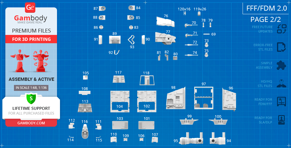
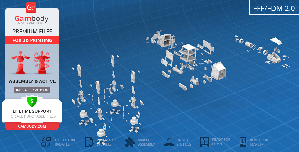
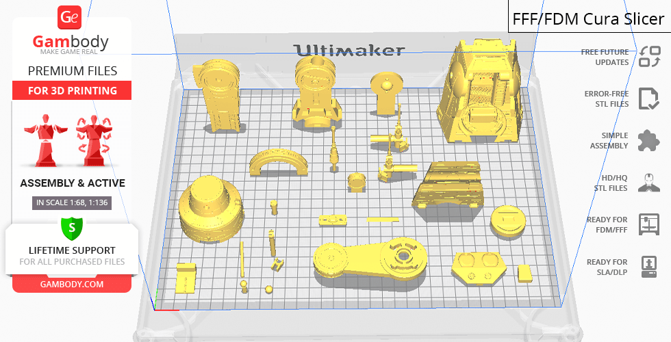
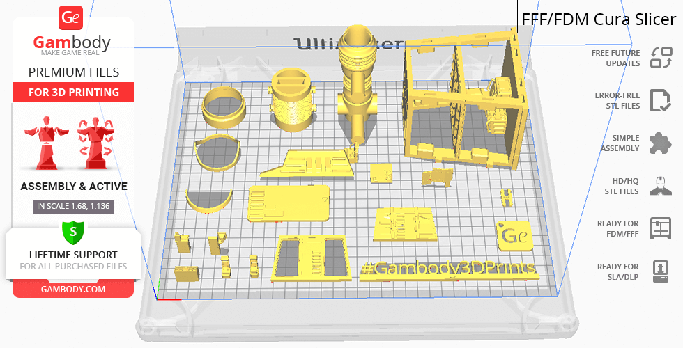
FFF/FDM
Assembly method
Connectors, Ge-Locks
Features
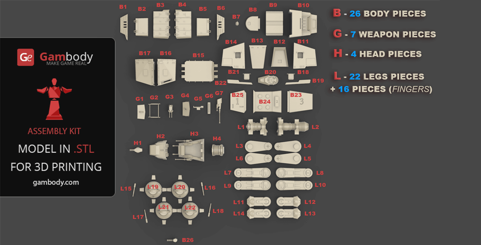
The assembly parts are connected using specially designed integrated connectors that fit securely into the corresponding slots. Made with a lock (120_Ge_lock_10H_(x16) that you need to print 16 times. Optionally, for added strength and rigidity, the parts can be glued together. The updated version of the model with a significantly enhanced level of detail, completely reworked joints, and articulated elements;
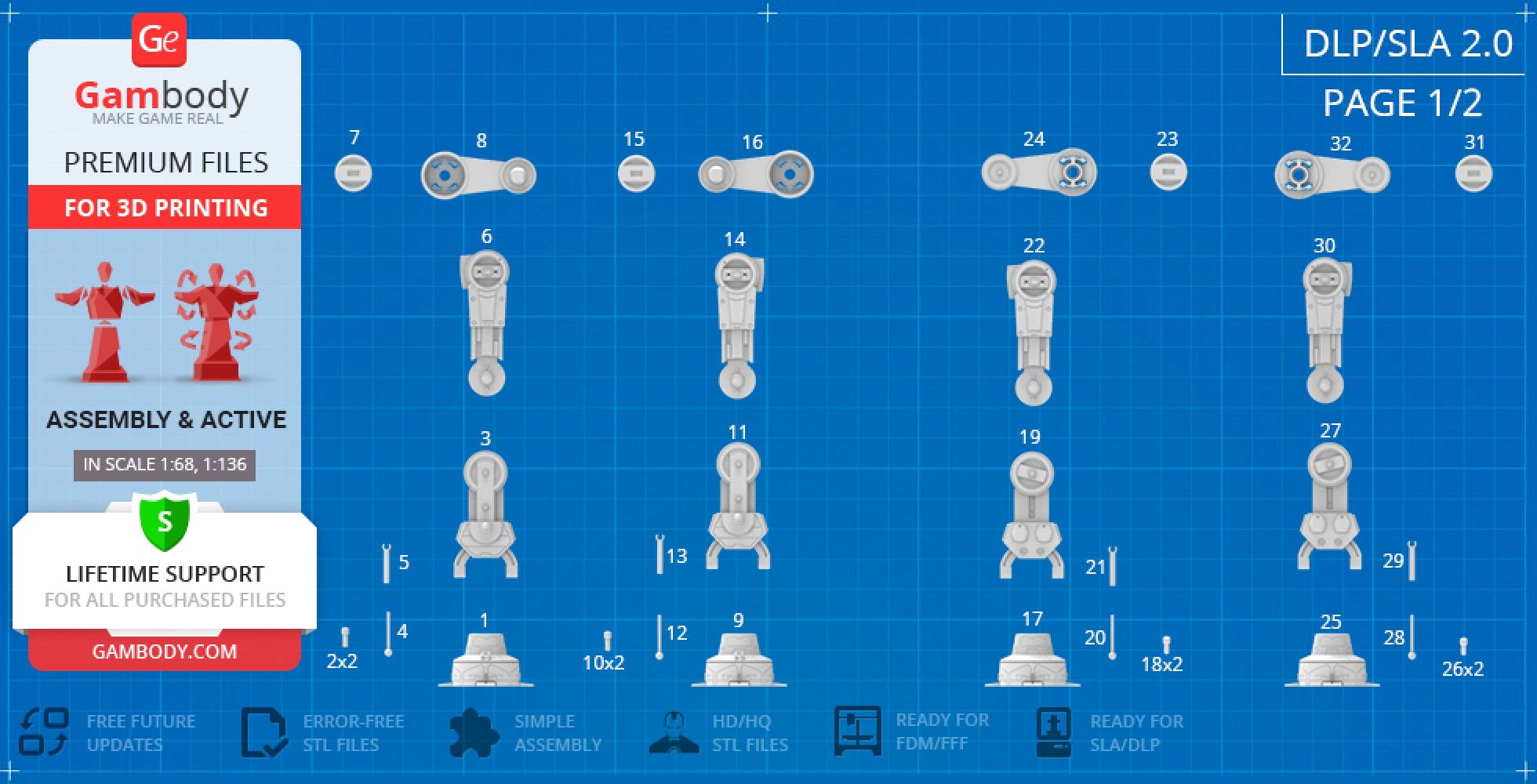
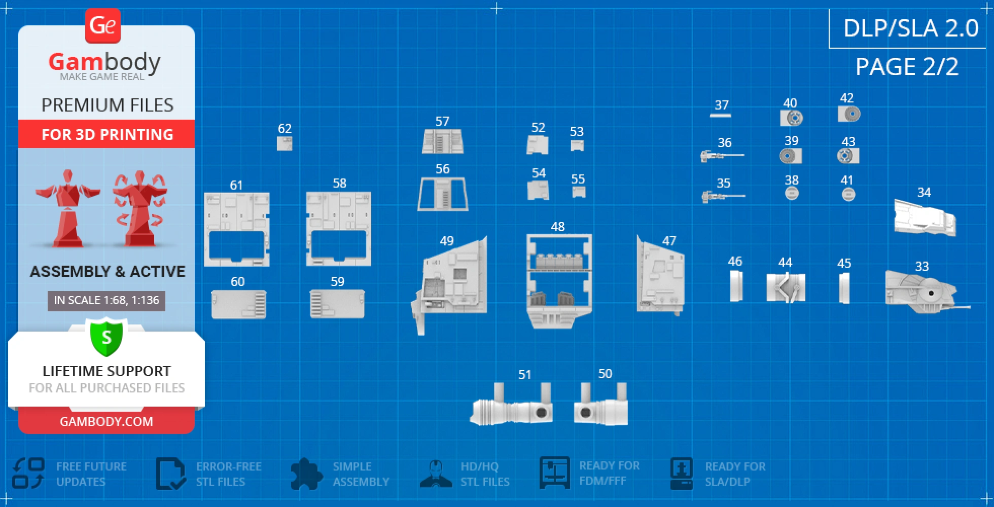
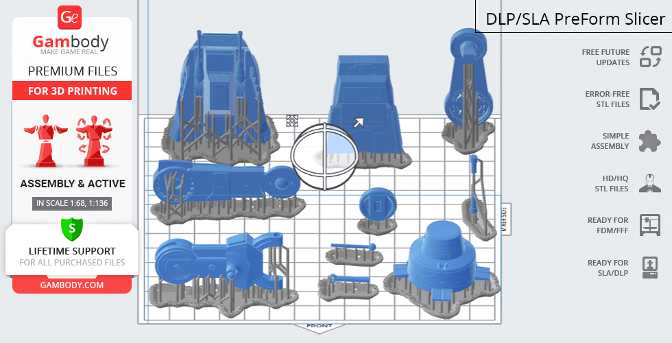
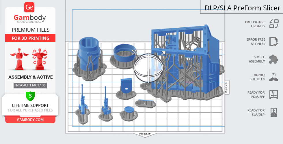
DLP/SLA
Eco parts
Assembly method
Connectors
Features
The assembly parts are connected using specially designed integrated connectors that fit securely into the corresponding slots. Optionally, for added strength and rigidity, the parts can be glued together. The updated version of the model with a significantly enhanced level of detail, completely reworked joints, and articulated elements;
FFF/FDM
Assembly method
Connectors, Glue
Features
The initial version of the AT-AT 3D printing model was released in 2015;
No assembly instruction is available;
Additional details
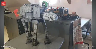
Part of diorama
No
Special pack included
No
You can get the STL files of the AT-AT Walker model immediately after the purchase! Just click the green Buy button in the top-right corner of the model’s page. You can pay with PayPal or your credit card.
Watch the tutorial on how to assemble the 3D Printed AT-AT Walker model from the provided 3D Print Files at the Gambody YouTube channel.
Also, you may like other All-terrain vehicles 3D Print Models, as well as other Movie 3D Printing Designs.
_______
FAQ:
This 3D model comes with StereoLithography (.STL) files optimized for 3D printing. You'll get digital files, not a physical product
Before printing, take a look at Printing Details for recommended settings and tips to achieve better results.
AT-AT Walker 3D Printer Files | Assembly includes 2 version(s) for the supported 3D printer type(s): FFF/FDM, DLP/SLA. Files are available for download after purchase.
See the Description and Specifications sections for more details about this model.
3D model history
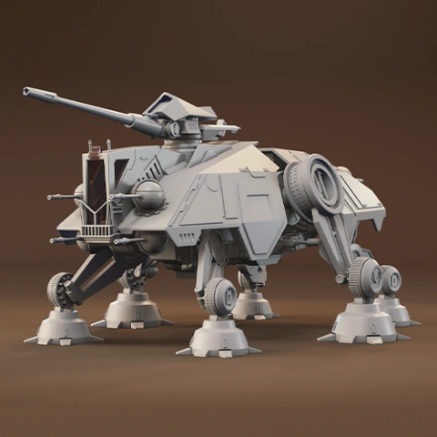
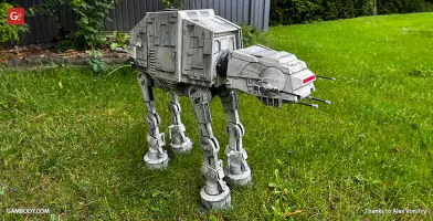
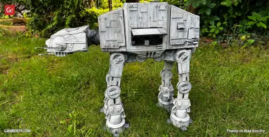
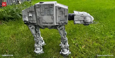
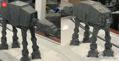
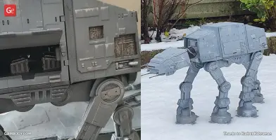
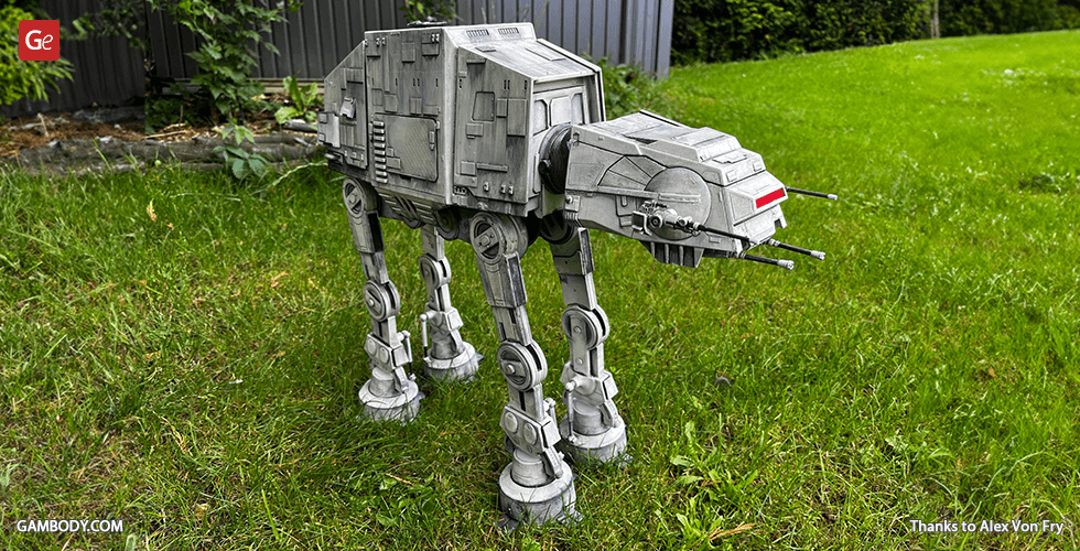
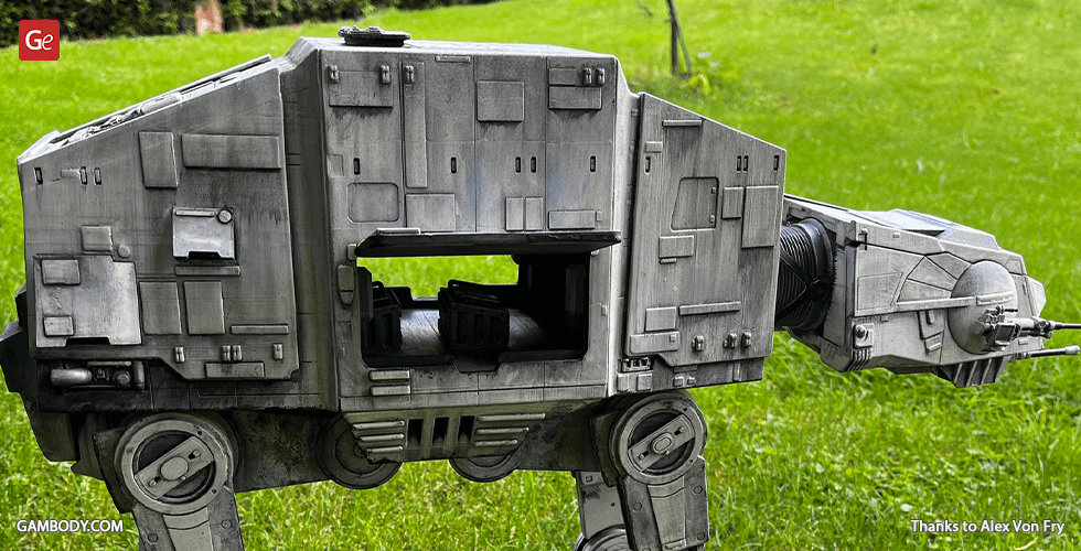
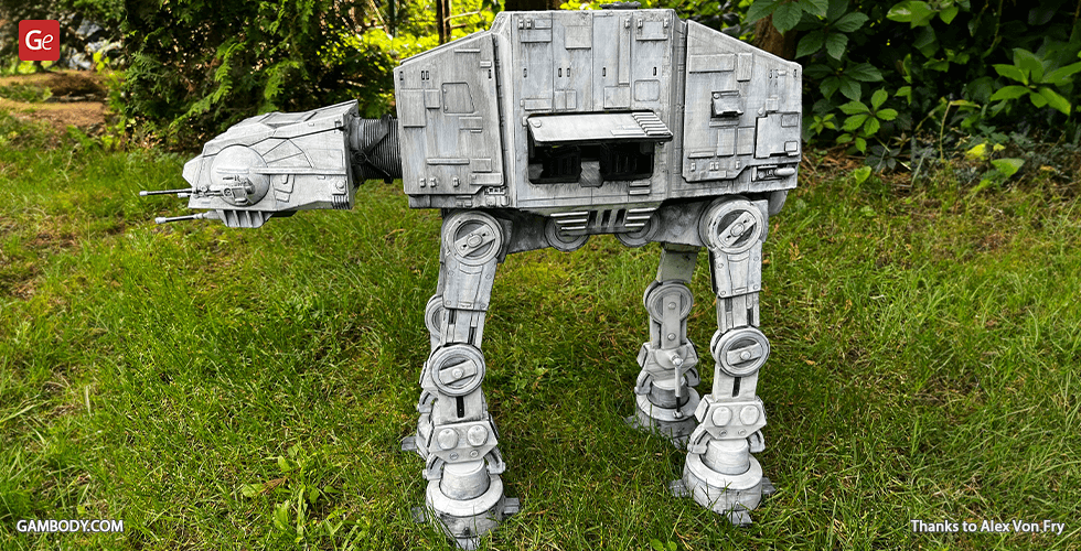
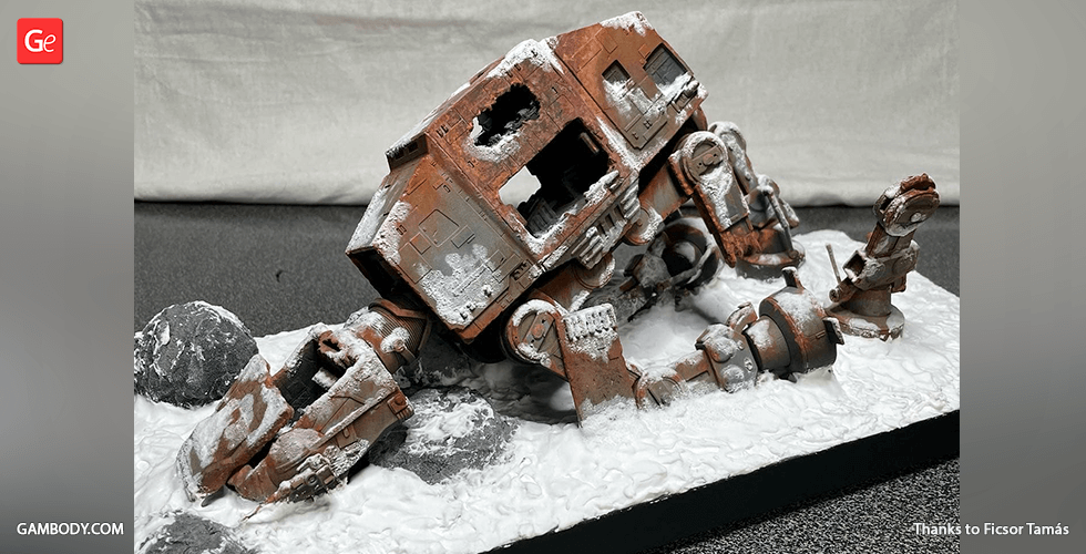
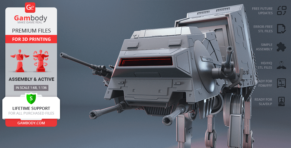
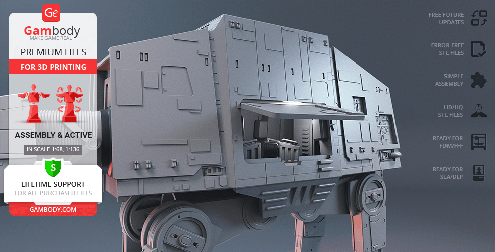
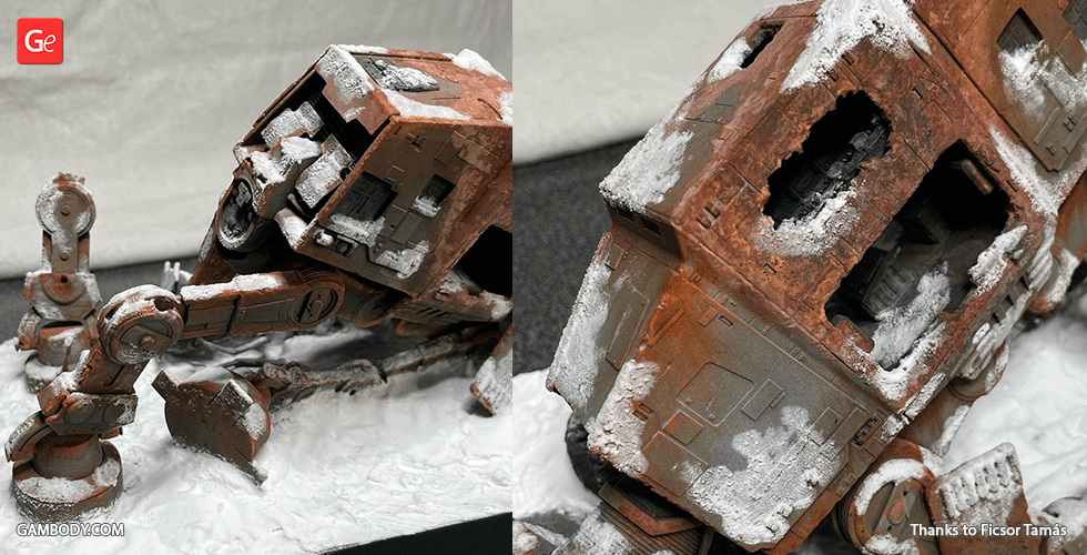
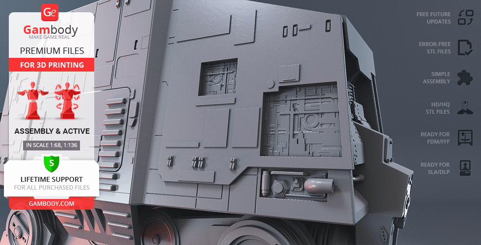
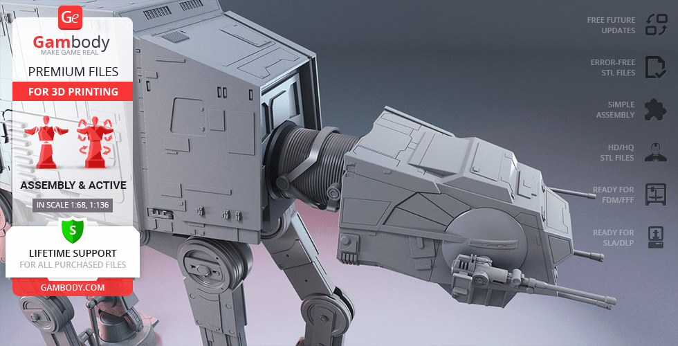
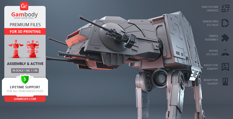
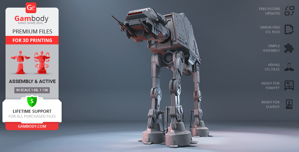
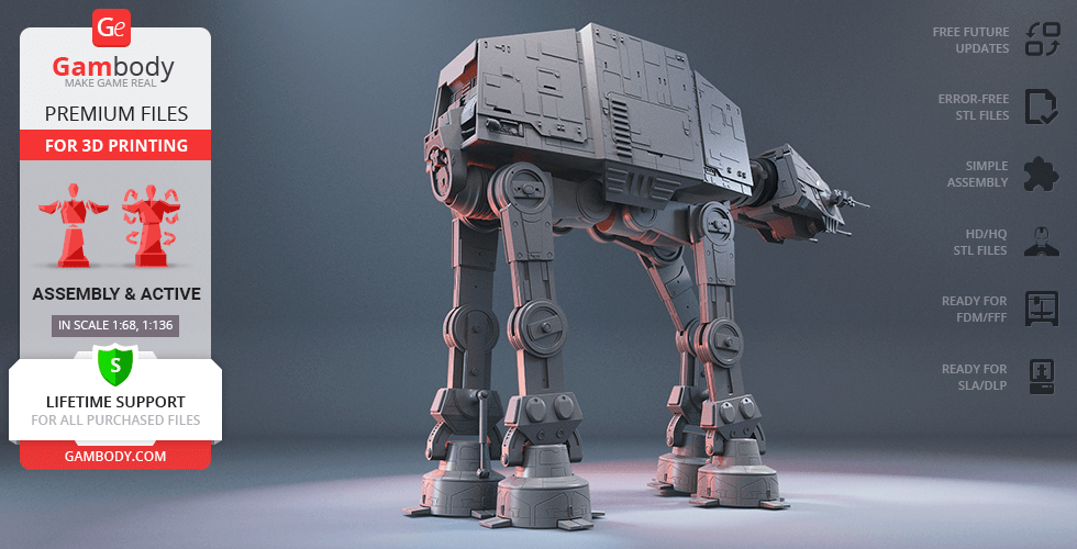
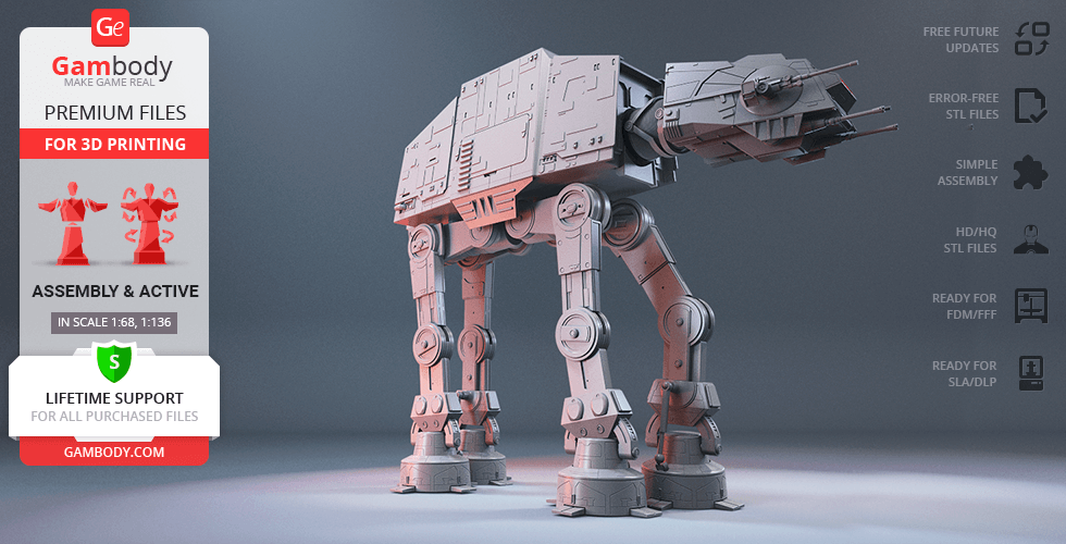
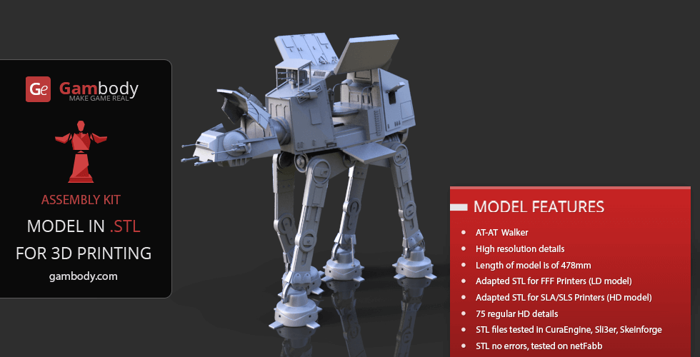
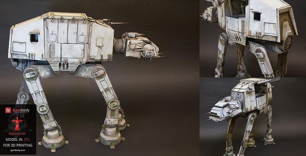
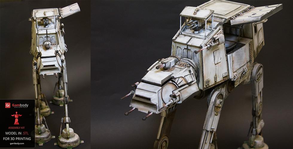
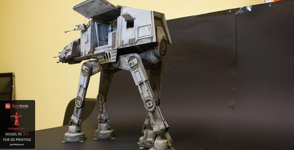
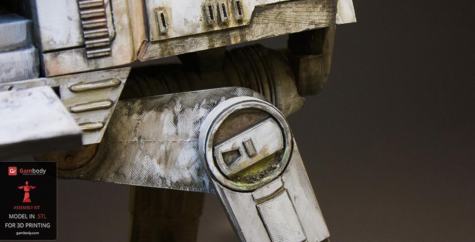
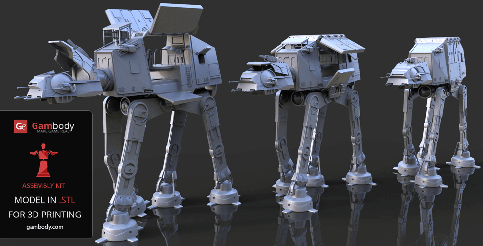
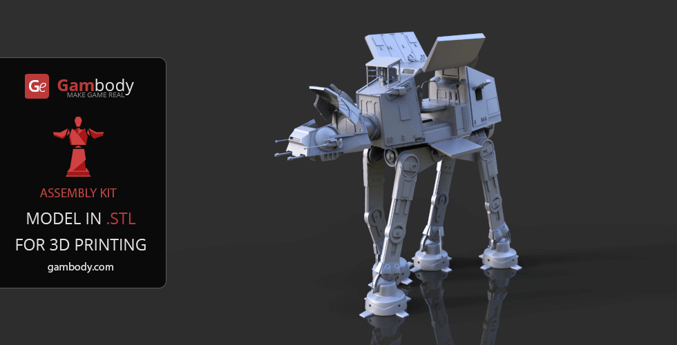
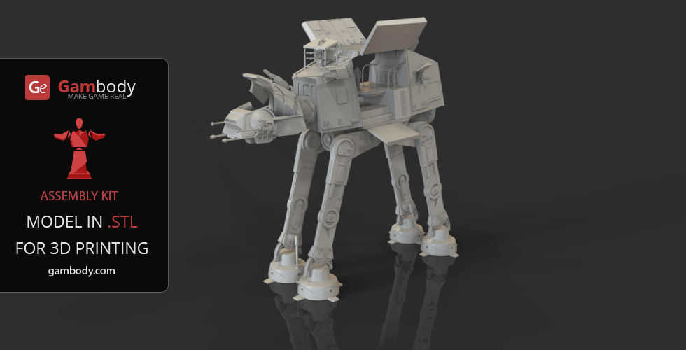
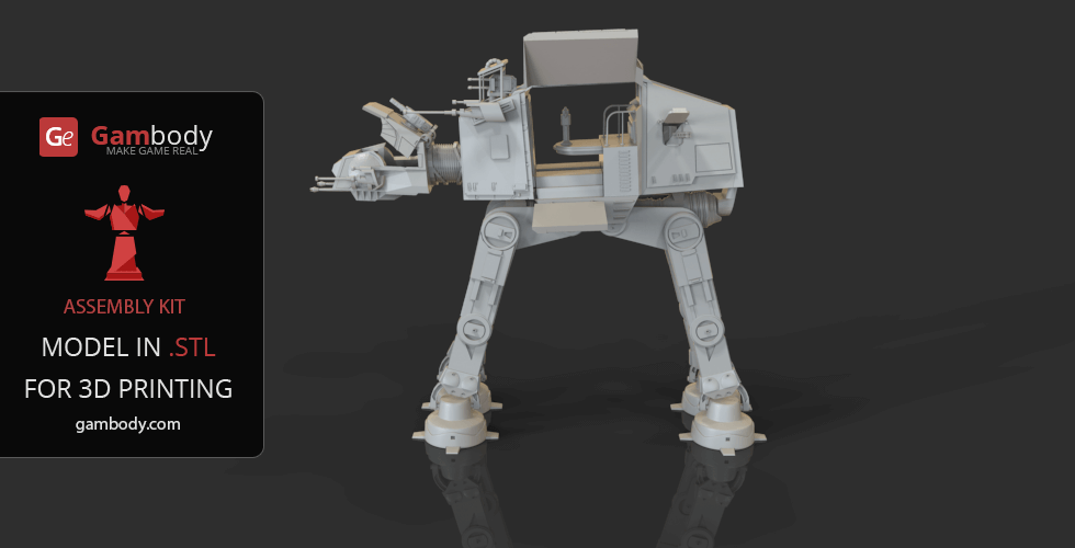
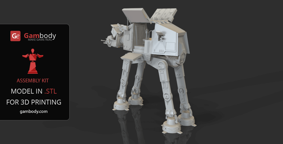
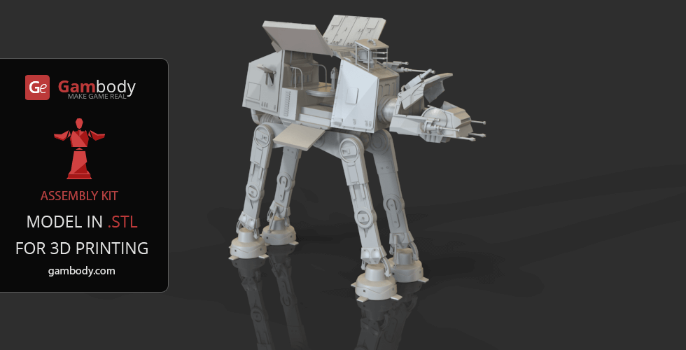
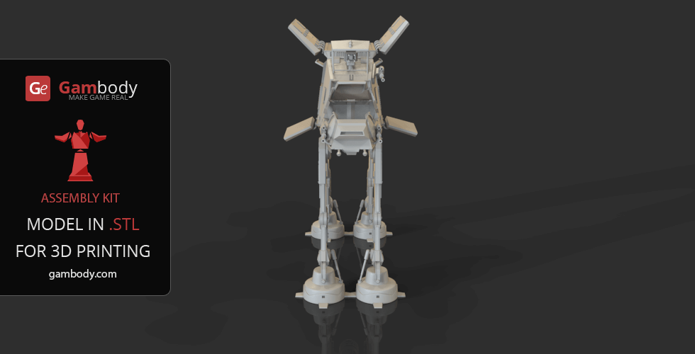
The ferocious All Terrain Armored Transport (AT-AT) is a quadrupedal combat Walker, the Imperial Army’s most famous and menacing ground weapon and an incontestable star of George Lucas' franchise. AT-ATs achieved their legendary status after the iconic battle on the ice plains of Hoth that resulted in a successful attack on Echo Base that protected the Rebel headquarters. Despite Walker’s many flaws and vulnerabilities, it has proved to be an excellent psychological weapon enough to make the enemy yield. With its terrifying main guns, massive size, tremendous design, and surprising pace, the AT-AT Walker can terrify the enemies with its mere appearance. The author of the imposing AT-AT model definitely wanted his Walker selection to boast one of the most recognizable symbols of the Empire's military strength. Massive and powerful, AT-AT model is heavily armed, carrying the twin chin-mounted Class II heavy laser cannons, and a pair of medium blaster cannons on its cheeks. Shielded with heavy armour cladding, the Walker 3D print model distinguishes by its spectacular level of detail of both the exterior and interior elements. The 3D artist made sure to carefully outfit the two-pilot cockpit and the two-story cabin that is known to carry up to 40 troopers to their deployment site. Various hatches and lids all over the body of this destructive weapon conceal the highly-detailed mechanical elements that would allow you to present the 3D printed AT-AT in a variety of scenarios or conditions. While the slow and vulnerable AT-AT might fail reality test, it is simply impossible to deny the fact that this Walker is a truly legendary beast of the Star Wars franchise. Get yourself your very own behemoth of a war machineby 3D printing the astonishing AT-AT Walker model!
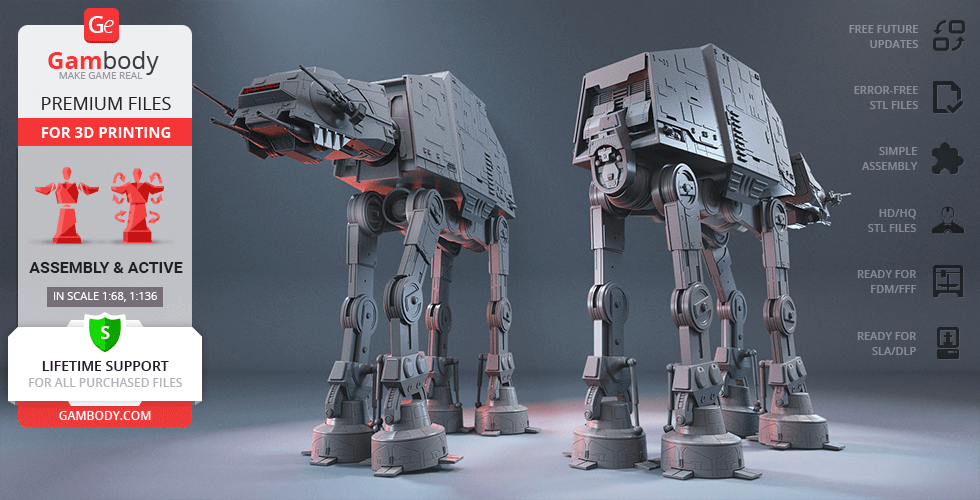
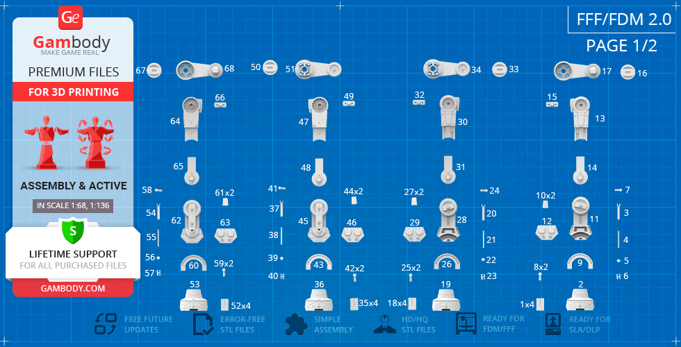
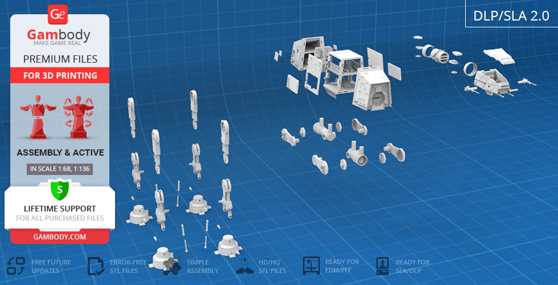
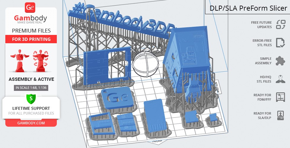
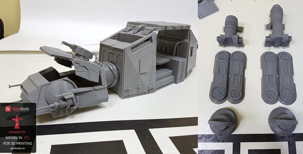
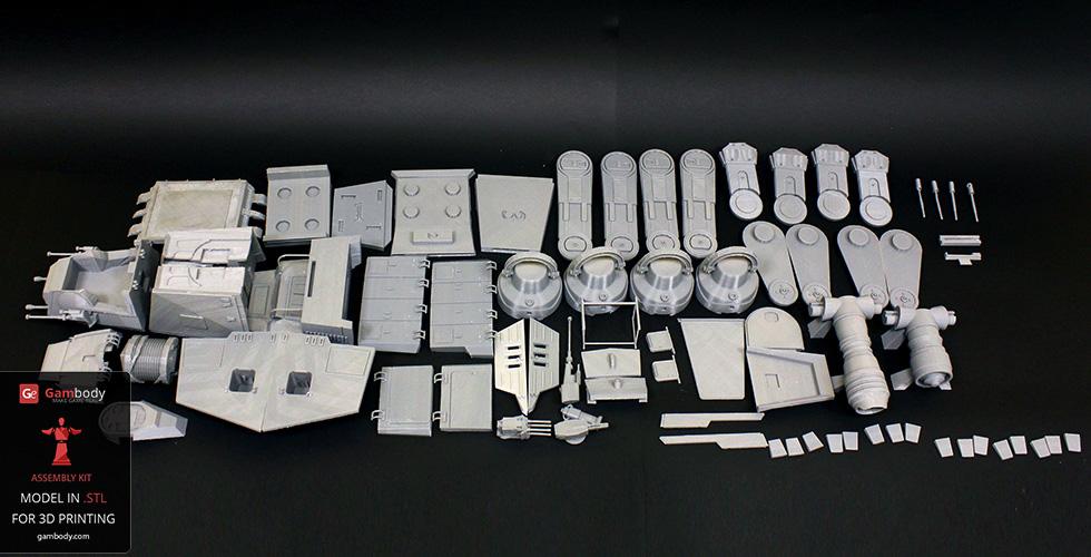
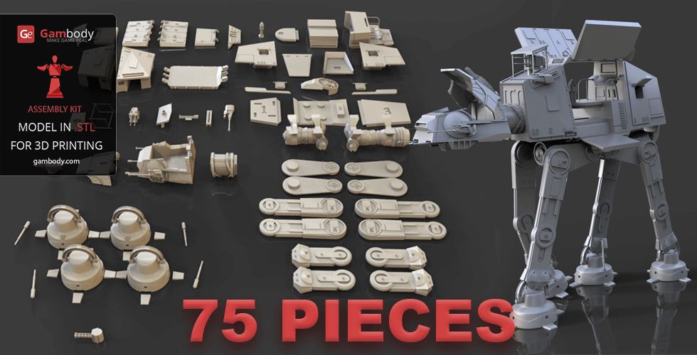
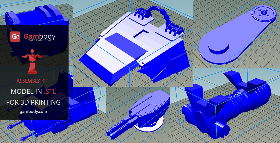
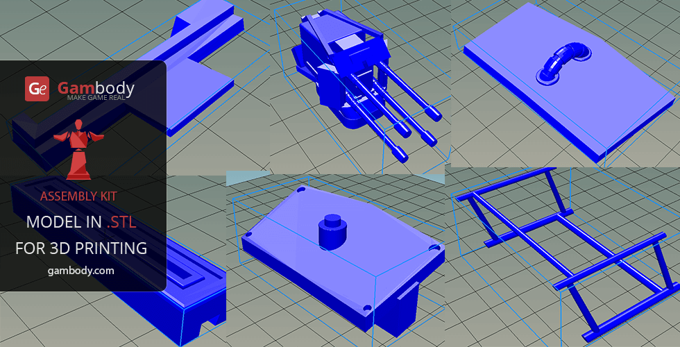
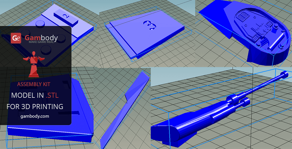
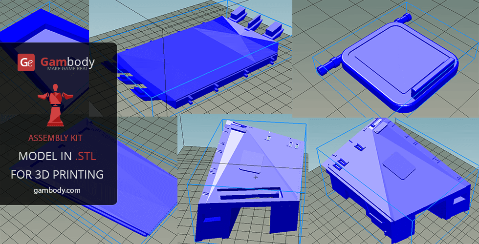
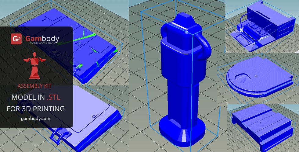
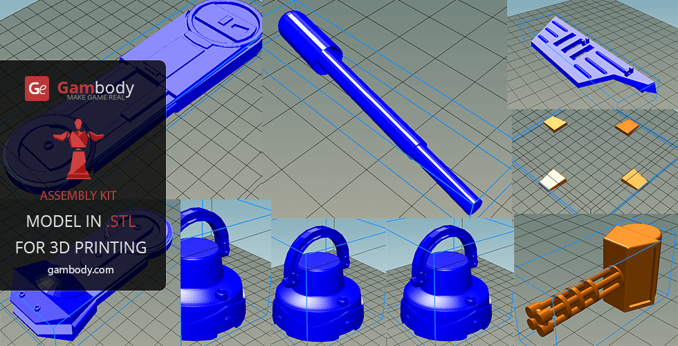
AT-AT Walker 3D printing design is an active assembly model and its updating and adaptation for different types of 3D printers took Gambody team 75 hours in total. Due to the fact that this model was first released on Gambody back in 2015, for all the Star Wars fans to print the best Walker possible, the model was upgraded from the ground up, cut into assembly parts anew, equipped with the latest developed articulated connecting elements and adapted for different types of 3D printers taking into account the present-day technology advancements. What is more, when preparing the model's update its level of detail and accuracy were significantly enhanced. Thus, for you to receive the cleanest 3D printing result possible and to minimize the amount of filament needed for generated support the Walker model was divided into many assembly parts, e.g. its blaster cannons, footpads, various hatches, viewport, heavy laser cannons, toe flaps, etc. are provided as separate STL files.
3D printing model features
Model-specific features:
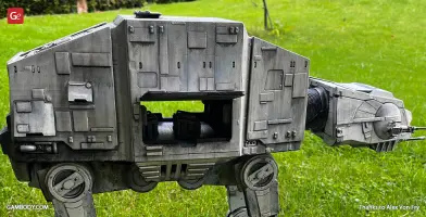
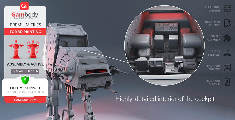
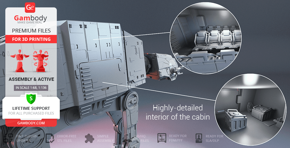
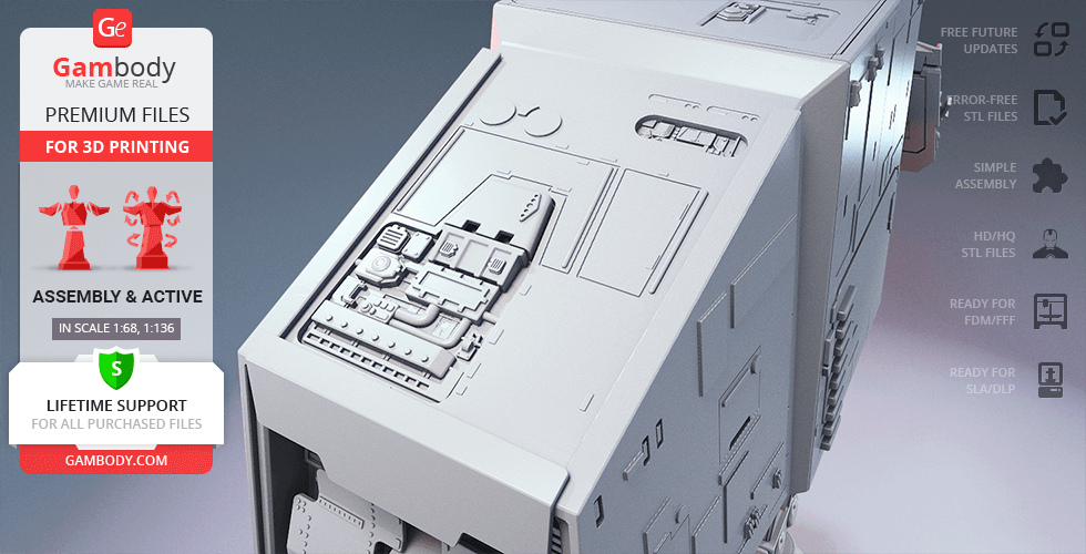
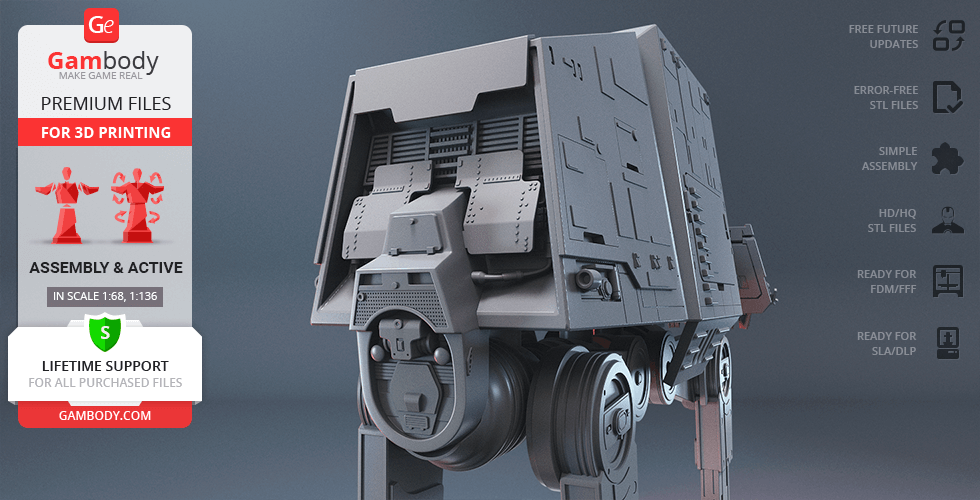
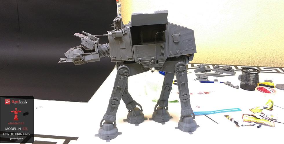
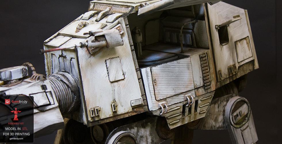
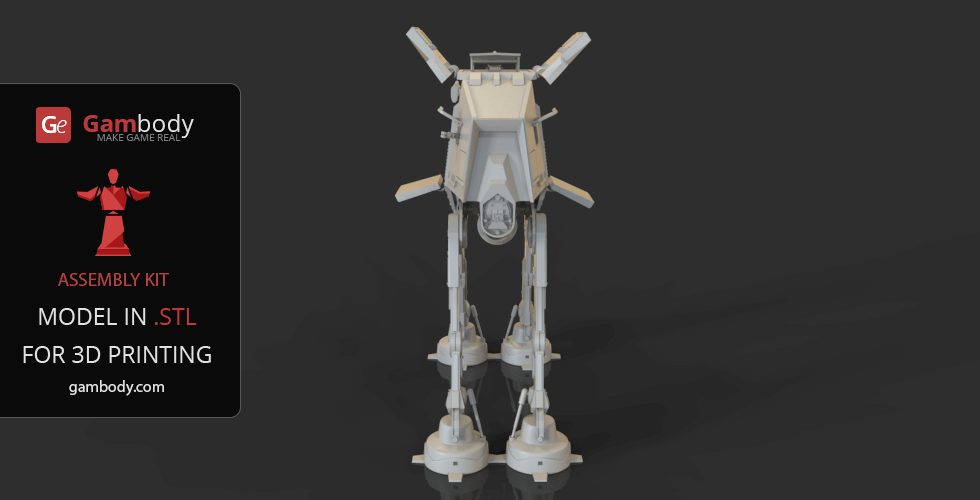
- The model’s head and body in both FFF/FDM 2.0 and DLP/SLA/SLS 1.0 versions are made hollow and have the highly detailed interior of the cockpit and the cabin;
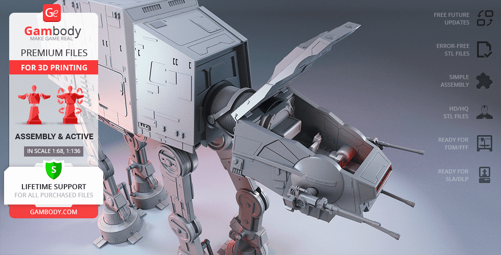
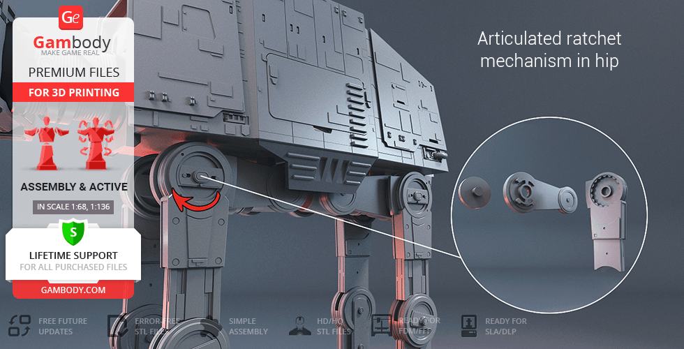
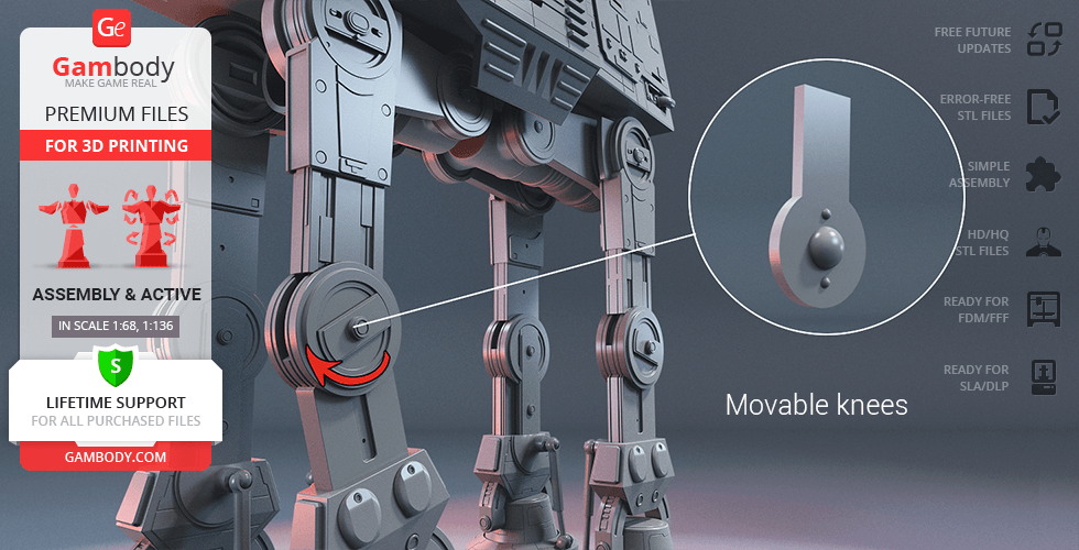
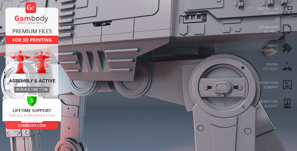
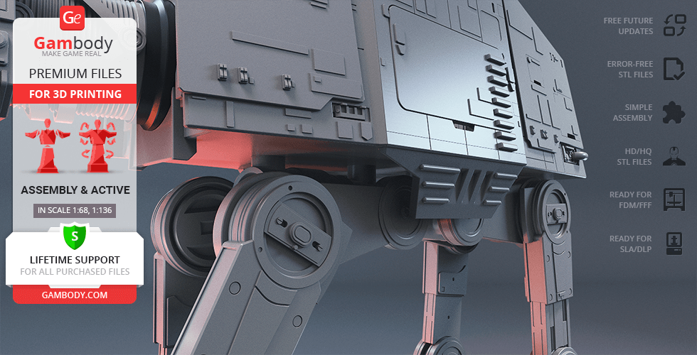
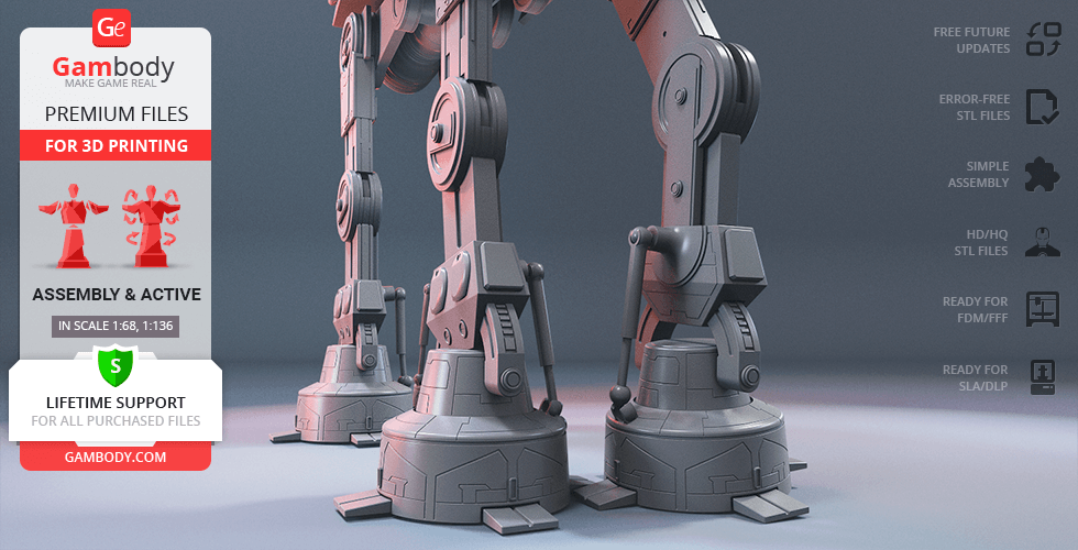
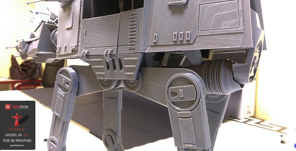
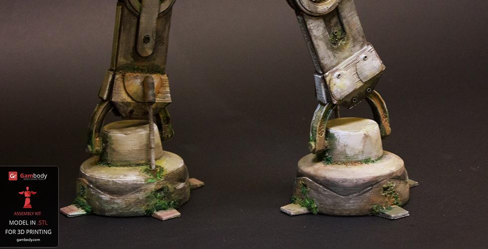
- Made with several sets of special joints to ensure the model's articulation (ankle, knee, hip and neck joints are movable);
- For the highly articulated Walker to stand firmly in any position you may choose there was a ratchet mechanism introduced into the model’s main joints (knee, hip, and neck);
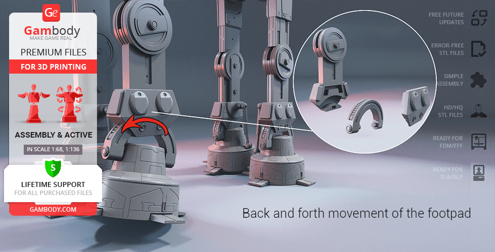
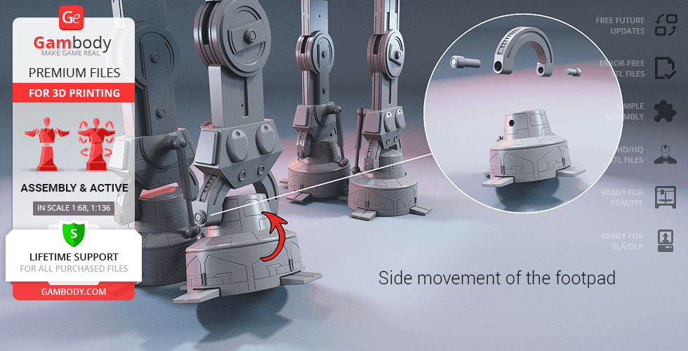
- The assembly of the model's footpad and ankle allows the multidirectional articulation of the element;
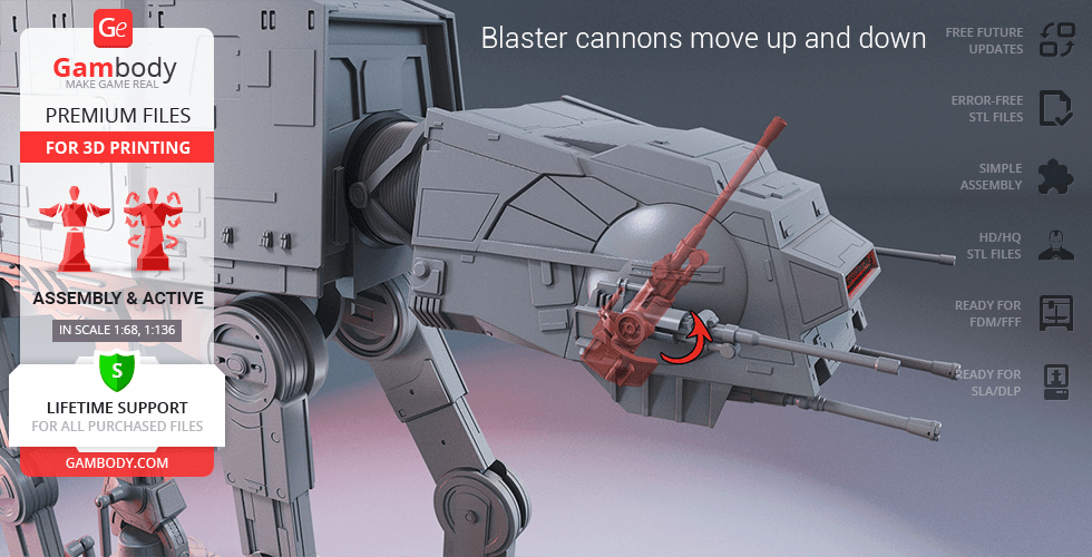
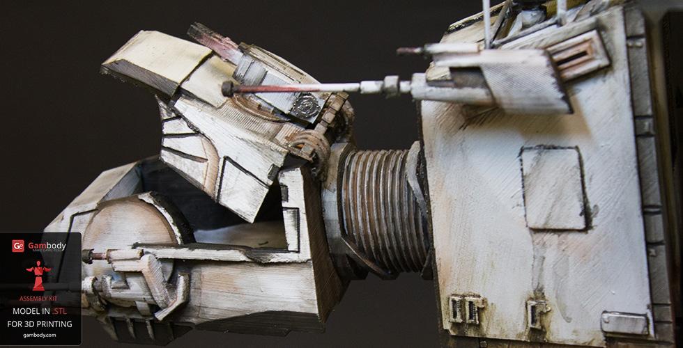
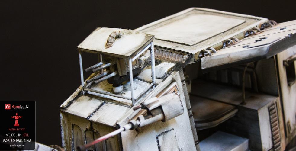
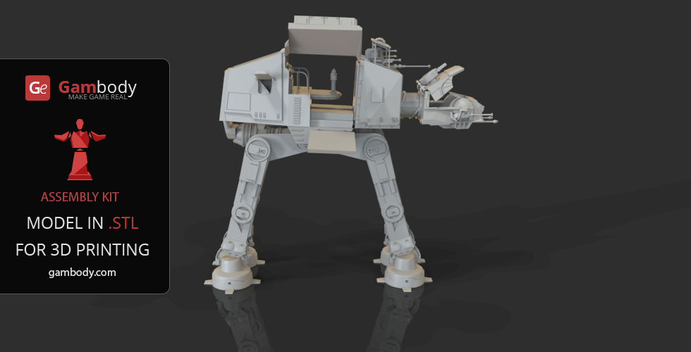
- The Walker's chin-mounted medium blaster cannons move up and down;
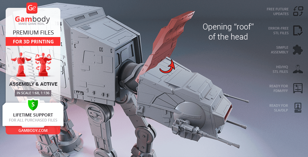
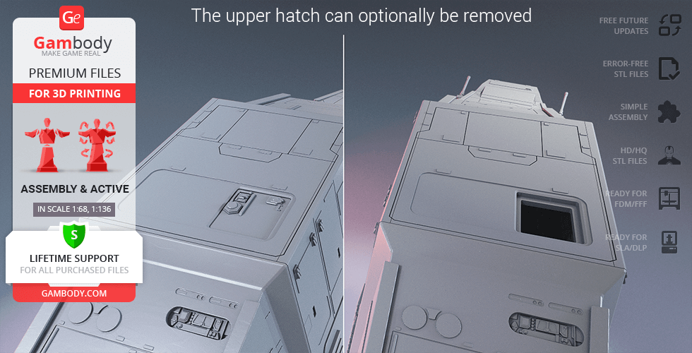
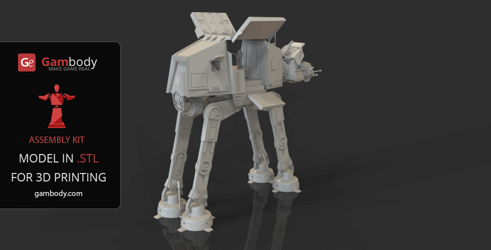
- The “roof” of the head opens to access the highly-detailed interior of the cockpit;
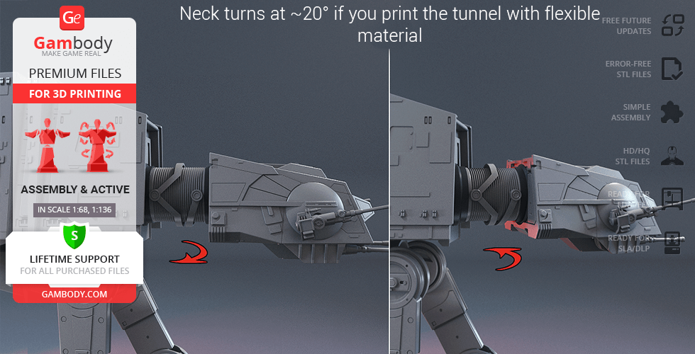
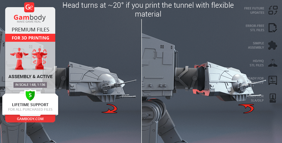
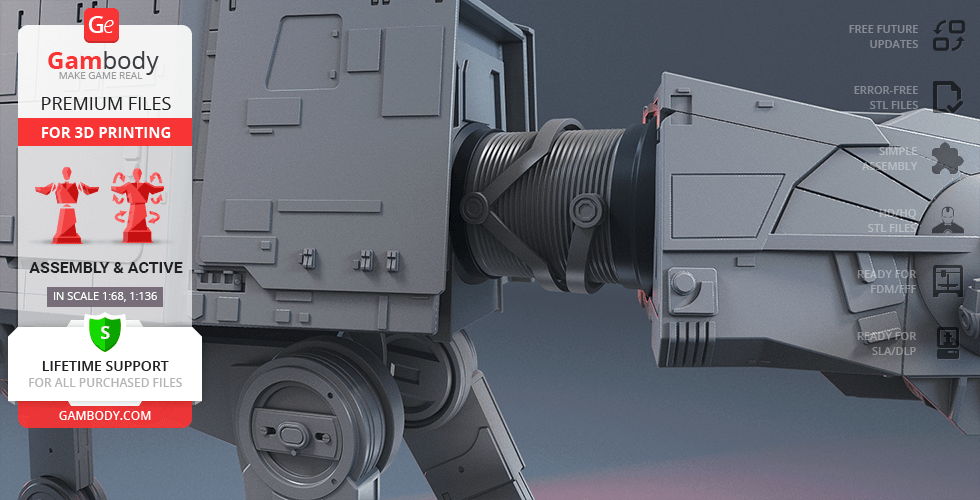
- The Walker's head and neck turn at ~20° if you print the tunnel (crimped neck) with flexible material;
- The pilot's viewport comes separately in order to be printed with transparent material;
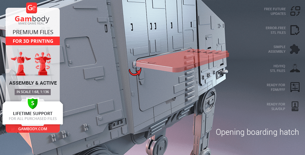
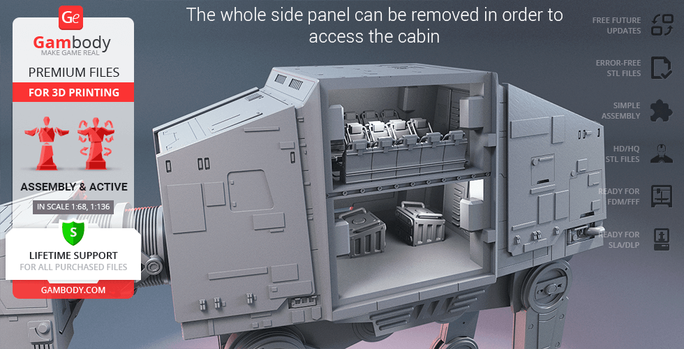
- The boarding hatch on the side of the Walker opens, and one side panel can be removed completely in order to access the highly-detailed interior of the cabin;
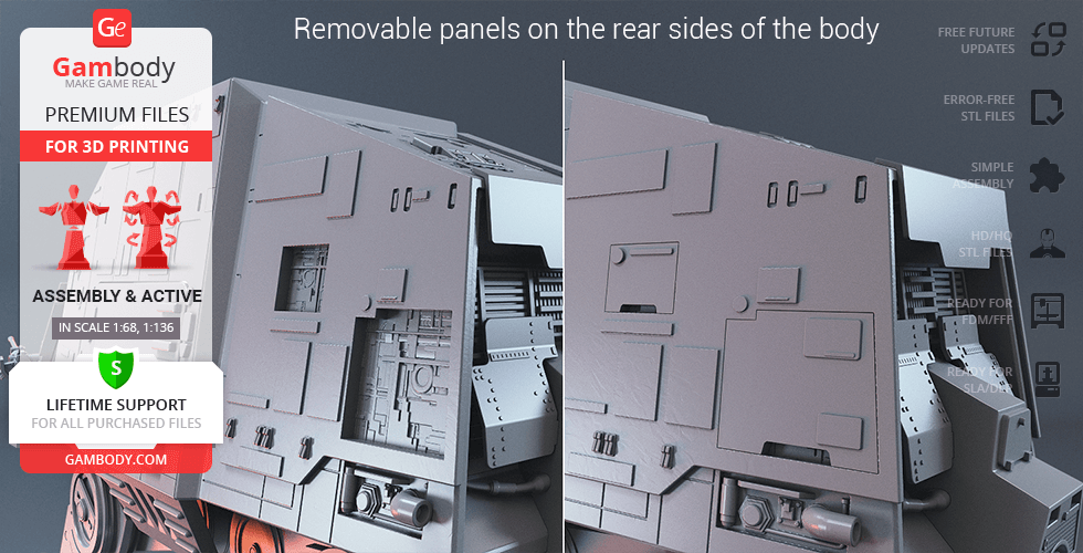
- There are various panels and hatches all over Walker's body that can be optionally removed;
- Designed for LED lighting: Includes tunnels to light up the model's cockpit and cabin.
Printing & assembly details:
- Provided as error-free STL files compatible with most 3D printers;
- Optimized part division minimizes support material and ensures smooth surface detail;
- The assembly parts in the FFF/FDM version come in the recommended print orientations for easy bed placement;
- Assembly manual in PDF and video formats is included for both FFF/FDM and DLP/SLA/SLS versions;
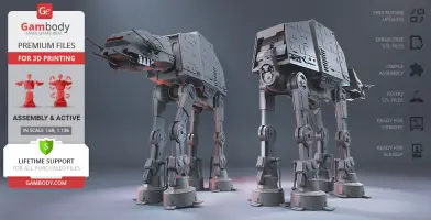
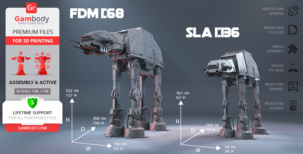
- The model is available in recommended scales of 1:68 for the FFF/FDM version and 1:136 for the DLP/SLA/SLS version, based on the actual length of the AT-AT which is 26000 mm.
What will you get after purchase?
- 3 versions of AT-AT WalkerSTL files for FFF/FDM, DLP/SLA/SLS — files for all versions are available for download after the purchase;
- STL files of high-poly AT-AT Walker model for 3D printing consist of 182 files;
- Sizes for:
- FFF/FDM: 140 mm wide, 322 mm high, 396 mm deep;
- DLP/SLA/SLS: 70 mm wide, 161 mm high, 198 mm deep;
- Assembly Manual for FFF/FDM 2.0 and DLP/SLA 1.0 versions in PDF and video formats;
- Detailed settings that we provide as a recommendation for Bambu Studio, Cura, Orca Slicer, PrusaSlicer, Simplify3D, and Slic3r for the best print;
- Full technical support from the Gambody Support Team.
Average customer rating (60 reviews)
4.1
Ratings breakdown
Click a star rating to filter reviews
Overall experience
Level of detail in the model
4.1
Model cut quality and assembly guide
4.1
Clarity and accuracy of the model page
4.1
Level of detail in the model
5
Model cut quality and assembly guide
5
Clarity and accuracy of the model page
5
Level of detail in the model
5
Model cut quality and assembly guide
5
Clarity and accuracy of the model page
5
Level of detail in the model
5
Model cut quality and assembly guide
5
Clarity and accuracy of the model page
5
Level of detail in the model
5
Model cut quality and assembly guide
5
Clarity and accuracy of the model page
5
Level of detail in the model
4
Model cut quality and assembly guide
4
Clarity and accuracy of the model page
4
Level of detail in the model
4
Model cut quality and assembly guide
4
Clarity and accuracy of the model page
4
Level of detail in the model
2
Model cut quality and assembly guide
2
Clarity and accuracy of the model page
2
Level of detail in the model
5
Model cut quality and assembly guide
5
Clarity and accuracy of the model page
5
Level of detail in the model
5
Model cut quality and assembly guide
5
Clarity and accuracy of the model page
5
Level of detail in the model
3
Model cut quality and assembly guide
3
Clarity and accuracy of the model page
3
Level of detail in the model
5
Model cut quality and assembly guide
5
Clarity and accuracy of the model page
5
Level of detail in the model
5
Model cut quality and assembly guide
5
Clarity and accuracy of the model page
5
Level of detail in the model
2
Model cut quality and assembly guide
2
Clarity and accuracy of the model page
2
Level of detail in the model
2
Model cut quality and assembly guide
2
Clarity and accuracy of the model page
2
Level of detail in the model
3
Model cut quality and assembly guide
3
Clarity and accuracy of the model page
3
Level of detail in the model
4
Model cut quality and assembly guide
4
Clarity and accuracy of the model page
4
Level of detail in the model
5
Model cut quality and assembly guide
5
Clarity and accuracy of the model page
5
Level of detail in the model
4
Model cut quality and assembly guide
4
Clarity and accuracy of the model page
4
Level of detail in the model
2
Model cut quality and assembly guide
2
Clarity and accuracy of the model page
2
Level of detail in the model
2
Model cut quality and assembly guide
2
Clarity and accuracy of the model page
2
Below you'll find detailed slicing settings for Bambu Studio 2.0+, Orca Slicer 2.0+, UltiMaker Cura 5.0+, PrusaSlicer 2.0+, Slic3r 1.3+, Simplify3D 5.0+ to help you get the best results when printing this model. These settings are optimized specifically for this 3D model, but please note they may need slight adjustments depending on your printer or filament. When in doubt, refer to your printer's user manual.
To avoid printing issues and achieve the best quality, we highly recommend applying the following settings:
For better quality use 0.12 mm layer height, for fast printing use 0.2 mm layer height. For pins and the Ge connectors, use 0.2 layer height.
120-150% of your Layer Height
But you can paint the seam if you want.
You have to calibrate this parameter
You have to calibrate this parameter
You have to calibrate this parameter
For pins and power elements of the structure, such as the vehicle frame, use 3 loop
Disabled for vehicles and enabled for characters
For 0,2 Layer Height
The parameters in this tab vary greatly, it all depends on the quality of your printer. For example, if you have a classic Ender3, stick to the minimum parameters, but if you have a newer printer, for example Anycubic cobra 3 v2, you can select the maximum recommended values
Settings for advanced users, change these parameters only if you have sufficient 3D printing expertise
Enable this parameter if your model requires supports
We also recommend placing and removing supports manually in some places using special button
1-2 loops for more thick support
Top Z distance = 1-1.3 layer Height. If the supports are hard to remove, try increasing this setting by 0.1-0,4 mm
Bottom Z distance = 1-1.3 layer Height. If the supports are hard to remove, try increasing this setting by 0.1-0,4 mm
You have to calibrate this parameter which one is better for your filament
Increase this parameter if the supports are hard to remove from walls
For PLA and PETG filament types
5-8 mm is optional for small prints that have bad adhesion to the build plate
You have to calibrate this parameter
Read the description on your filament roll
Read the description on your filament roll and increase this parameter for fast printers
Read the description on your filament roll and increase this parameter for fast printers
For better quality use 0.12 mm layer height, for fast printing use 0.2 mm layer height. For pins and the Ge connectors, use 0.2 layer height.
120-150% of your Layer Height
But you can paint the seam if you want.
0.01-0.05 You have to calibrate this parameter
0.01-0.05 You have to calibrate this parameter
0.1-0.2 You have to calibrate this parameter
For pins and power elements of the structure, such as the vehicle frame, use 3 loop
Disabled for vehicles and ships, enabled for characters
For 0,2 Layer Height
For 0,2 Layer Height
The parameters in this tab vary greatly, it all depends on the quality of your printer. For example, if you have a classic Ender3, stick to the minimum parameters, but if you have a newer printer, for example, Anycubic Kobra 3 Or Bambulab A1, you can select the maximum recommended values.
Settings for advanced users, change these parameters only if you have sufficient 3D printing expertise
Enable this parameter if your model requires supports
We also recommend placing and removing supports manually in some places using special button
Top Z distance = 1-1.3 layer Height. If the supports are hard to remove, try increasing this setting by 0.1-0,4 mm
Bottom Z distance = 1-1.3 layer Height. If the supports are hard to remove, try increasing this setting by 0.1-0,4 mm
Increase this parameter if the supports are hard to remove from walls
For PLA and PETG filament types
5-8 mm is optional for small prints that have bad adhesion to the build plate
Read the description on your filament roll
Read the description on your filament roll and increase this parameter for fast printers
You have to calibrate this parameter
Read the description on your filament roll and increase this parameter for fast printers
Read the description on your filament roll
This field is filled in according to your printer specifications when you add it to the slicer.
You can add custom G-code here for the start and end of the print. However, be careful - this is for advanced users only!
You have to calibrate your printer using Ge retraction test models
Retraction Length: For direct-drive setups use 0.5 mm to 2.5 mm; for Bowden extruders use 5 to 7 mm
This is how fast the filament is pulled back—40-60 mm/s for direct drive and 30-50 mm/s for Bowden setups.
You have to calibrate this parameter: Reduce it until the printer starts to hit the parts with the nozzle during printing, then increase it by 0.2.
For better quality use 0.12 mm layer height, for fast printing use 0.2 mm layer height. For pins and the Ge connectors, use 0.2 layer height.
120-150% of your Layer Height
To increase the strength of the print parts, use wall line count: 3
For pins and connectors use 50% Infill
These parameters are for standard PLA plastic. If you are using a different type of plastic, check the printing temperature recommended by the manufacturer. Also, read the description on your filament spool. For fast printers, add +30 °C to the current parameters.
The parameters in this tab vary greatly, it all depends on the quality of your printer. For example, if you have a classic Ender3, stick to the minimum parameters, but if you have a newer printer, for example Anycubic cobra 3 v3, you can select the maximum recommended values
Settings for advanced users, change these parameters only if you have sufficient 3D printing expertise.
You need to calibrate this parameter using Gambody test models. These values are average values for a Direct Drive extruder; for a Bowden extruder, the values should be increased.
You need to calibrate this parameter using Gambody test models. These values are average values for a Direct Drive extruder; for a Bowden extruder, the values should be increased.
Use this value other than 0 if your nozzle catches on the internal infill during travel moves. Try to keep this value as low as possible in height.
Use normal supports to support large, straight surfaces (most mechanical or technical parts).
You have to calibrate this parameter according to the capabilities of your printer and your filament, using a Gambody test models.
Use 1 instead of 0 if your supports are thin and tall. They will be harder to remove, but much stronger.
Top Z distance = 1-1.3 layer Height. If the supports are hard to remove, try increasing this setting by 0.1-0,4 mm
Increase this parameter if the supports are hard to remove from walls
Use tree supports to support complex objects, such as characters.
You have to calibrate this parameter according to the capabilities of your printer and your filament, using a Gambody test models.
Top Z distance = 1-1.3 layer Height. If the supports are hard to remove, try increasing this setting by 0.1-0,4 mm
Increase this parameter if the supports are hard to remove from walls
Use a skirt for all parts when printing on outdated printers.
Use a brim when printing thin but tall parts, as well as parts with a small bed adhesion area.
For better quality use 0.12 mm layer height, for fast printing use 0.2 mm layer height. For pins and the Ge connectors, use 0.2 layer height.
120-150% of your Layer Height
for 0.2 Layer Height
But you can paint the seam if you want.
(for PLA and PETG)
(5-8 mm is optional for small prints that have bad adhesion to the build plate)
Enable this parameter if your model requires supports
(45-50 degree)You have to calibrate this parameter according to the capabilities of your printer
and your filament, using a Gambody test models.
Top contact Z distance = 1-1.3 layer Height. If the supports are hard to remove, try
increasing this setting by 0.1-0,4 mm
Top contact Z distance = 1-1.3 layer Height. If the supports are hard to remove, try
increasing this setting by 0.1-0,4 mm
Increase this parameter if the supports are hard to remove from walls
The parameters in this tab vary greatly, it all depends on the quality of your printer. For example, if you have a classic Ender3, stick to the minimum parameters, but if you have a newer printer, for example Anycubic cobra 3 v3, you can select the maximum recommended values
Settings for advanced users, change these parameters only if you have sufficient 3D printing expertise. Use the minimum value for outdated printers without acceleration calibration, and the maximum value for modern printers if you need it.
These settings only work for 3D printers with multiple extruders
You can try setting all parameters in this section, except the First layer, to values between 0.75% of your nozzle diameter and 1.25% of your nozzle diameter. Adjusting them will help you work out the optimal parameters for the best quality for your print. As for the First layer, you can set it to 150% of the diameter of your nozzle for better adhesion to the build plate (for a nozzle with a diameter of 0.4 mm, the First layer extrusion width can be from 0.3 mm to 0.5 mm)
For better printing quality you have to calibrate this parameter using Gambody test model.
Check your filament manufacturer's temperature recommendations on the spool.
Cooling parameters depends on the material you use for printing.
*for PLA
For better quality use 0.12 mm layer height, for fast printing use 0.2 mm layer height. For pins and the Ge connectors, use 0.2 layer height.
120-150% of your Layer Height
For 0.12 Layer Height
For 0.12 Layer Height
For pins and connectors use 50% Infill
Use skirt for outdated 3d printers
(5-8 mm is optional for small prints that have bad adhesion to the build plate)
Enable this parameter if your model requires supports
(45-60 degree)You have to calibrate this parameter according to the capabilities of your printer and your filament, using a Gambody test models
Contact Z distance = 1-1.3 layer Height. If the supports are hard to remove, try increasing this setting by 0.1-0,4 mm
The parameters in this tab vary greatly, it all depends on the quality of your printer. For example, if you have a classic Ender3, stick to the minimum parameters, but if you have a newer printer, for example Anycubic cobra 3 v3, you can select the maximum recommended values
Settings for advanced users, change these parameters only if you have sufficient 3D printing expertise. Use the minimum value for outdated printers without acceleration calibration, and the maximum value for modern printers if you need it.
You have to calibrate this parameter from 0.9 to 1.1 according to the capabilities of your printer and your filament, using a Gambody test models.
Check your filament manufacturer's temperature recommendations on the spool.
Cooling parameters depends on the material you use for printing.
Calibrate this value if you need to reduce or improve the adhesion between the plastic and the heat bed
Your current nozzle diameter
You need to calibrate this parameter using Gambody test models. These values are average values for a Direct Drive extruder; for a Bowden extruder, the values should be increased.
Your current nozzle diameter
You have to calibrate this parameter using Gambody test models.
You need to calibrate this parameter using Gambody test models. These values are average values for a Direct Drive extruder; for a Bowden extruder, the values should be increased.
For better quality use 0.12 mm layer height, for fast printing use 0.2 mm layer height. For pins and the Ge connectors, use 0.2 layer height.
For 0,2 Layer Height
For 0,2 Layer Height
To increase the strength of the print parts, use Outline Perimeters: 3
You can enable this parameter to print rounded or spherical models, as well as character models.
Use this option only if your parts are too tight. but better calibrate your printer extrusion
Use this option only if your parts are too tight. but better calibrate your printer extrusion
Use 2 and more if you want to create skirt instead brim
1-2 for skirt and 10-20 for brim
Use for wipe nozzle if you need
Use For ABS filament
For pins and connectors use 50% Infill
Top Z distance = 1-1.3 layer Height. If the supports are hard to remove, try increasing this setting by 0.1-0,4 mm
Calibrate your filament and detect optimal temperature for it
Average temperature for PLA filament
The parameters in this tab vary greatly, it all depends on the quality of your printer. For example, if you have a classic Ender3, stick to the minimum parameters, but if you have a newer printer, for example Anycubic cobra 3 v3, you can select the maximum recommended values
Settings for advanced users, change these parameters only if you have sufficient 3D printing expertise.
DLP/SLA
The assembly parts are connected using specially designed integrated connectors that fit securely into the corresponding slots. Optionally, for added strength and rigidity, the parts can be glued together. The updated version of the model with a significantly enhanced level of detail, completely reworked joints, and articulated elements;
FFF/FDM
The assembly parts are connected using specially designed integrated connectors that fit securely into the corresponding slots. Made with a lock (120_Ge_lock_10H_(x16) that you need to print 16 times. Optionally, for added strength and rigidity, the parts can be glued together. The updated version of the model with a significantly enhanced level of detail, completely reworked joints, and articulated elements;
FFF/FDM
The initial version of the AT-AT 3D printing model was released in 2015;
No assembly instruction is available;