

Files
3D model format
Stereolithography (.stl)
Total files
Slicer settings
Mesh error check
Netfabb
Support
Lifetime support from Gambody team
Update requests
Available to verified buyers
Model complexity
Advanced: may require tuning print settings or support placement, plus precise fitting, gluing, or sanding.
Model versions
FFF/FDM
Assembly method
not specified
Features
DLP/SLA
Assembly method
not specified
Features
DLP/SLA
Assembly method
not specified
Features
Additional details
Part of diorama
No
Special pack included
No
You will get instant access to the STL files of Juggernaut Turbo Tank 3D Printing Model | Assembly after completing your purchase. Simply add the model to your cart and check out using PayPal, credit or debit card, Apple Pay, Google Pay, Alipay, or other available payment methods.
Watch the assembly video for Juggernaut Turbo Tank 3D Printing Model | Assembly, and explore more tutorials, behind-the-scenes content, 3D printing timelapses, and painting guides on the official Gambody YouTube channel.
This 3D Model consists of files in StereoLithography (.Stl) format that is optimized for 3D printing.
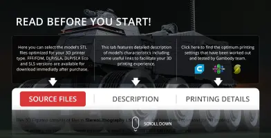
Before printing the files, we strongly recommend reading the PRINTING DETAILS section.
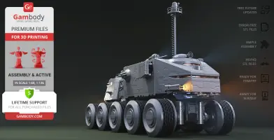
Juggernaut Turbo Tank 3D Printing Model comes in 3 versions for each 3D printer type (FFF/FDM and DLP/SLA/SLS). Files for each version are available for download after the purchase.
Detailed information about this 3D printing model is available in the DESCRIPTION section.
Before printing, take a look at Printing Details for recommended settings and tips to achieve better results.
ABOUT THIS 3D MODEL
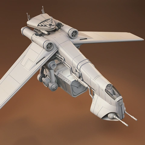
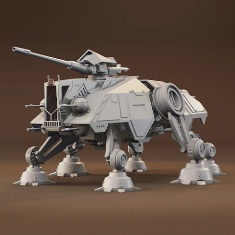
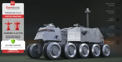
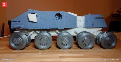
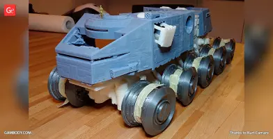
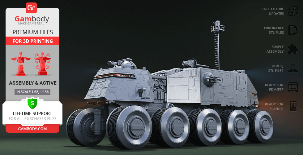
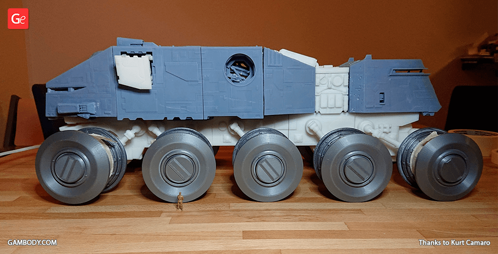
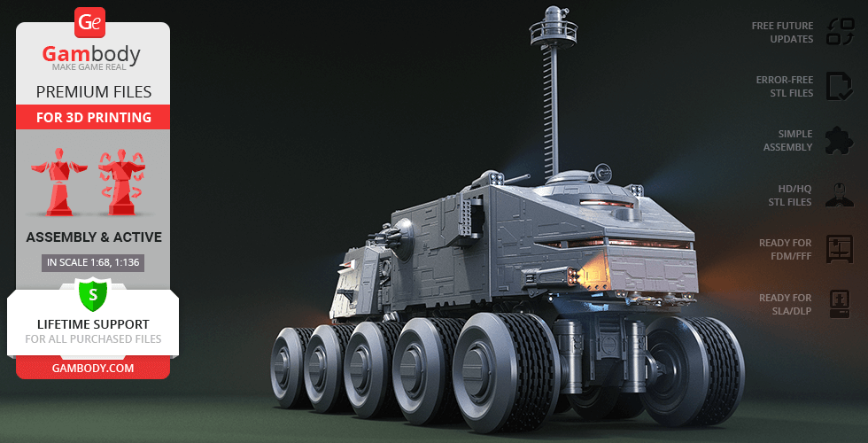
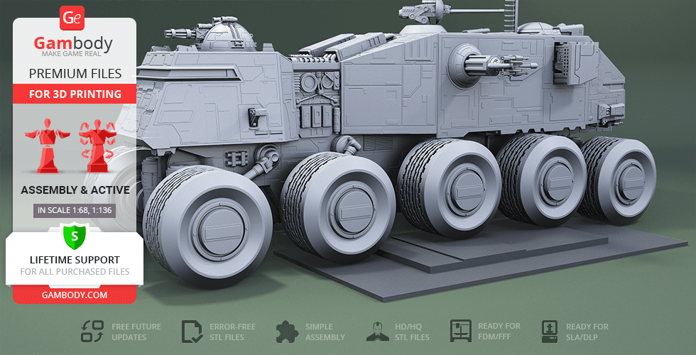
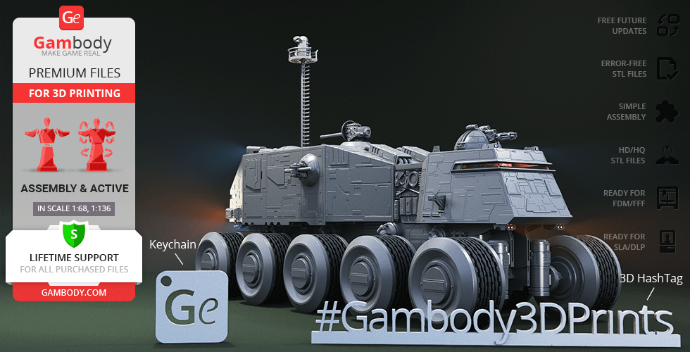
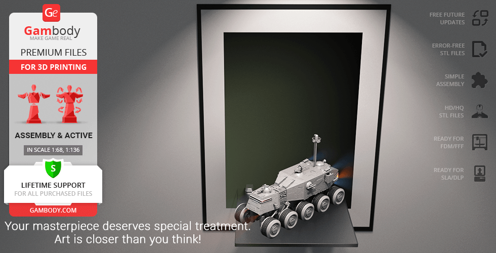
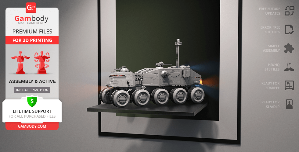
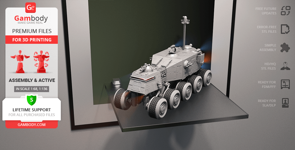
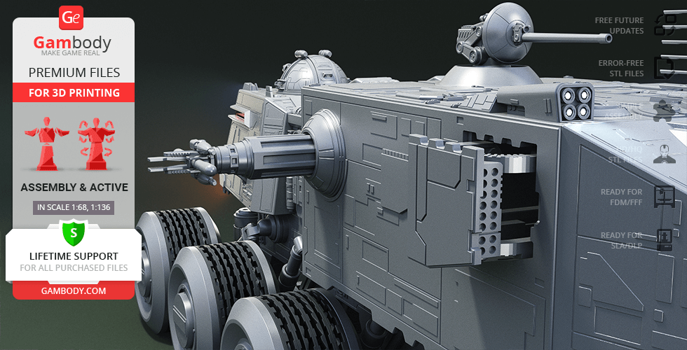
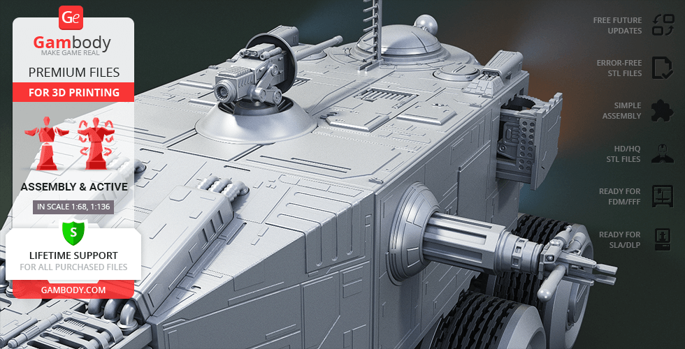
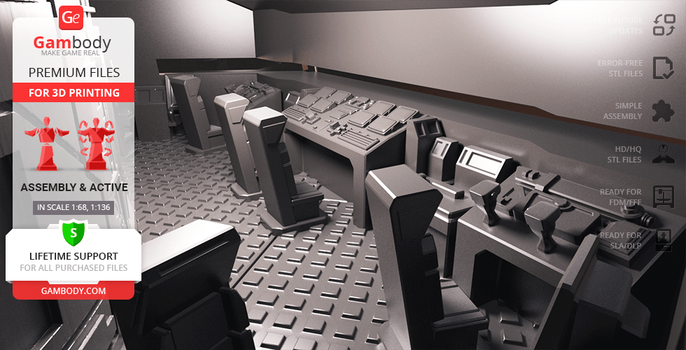
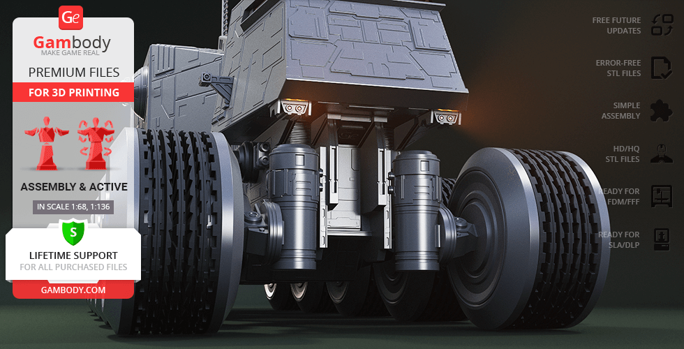
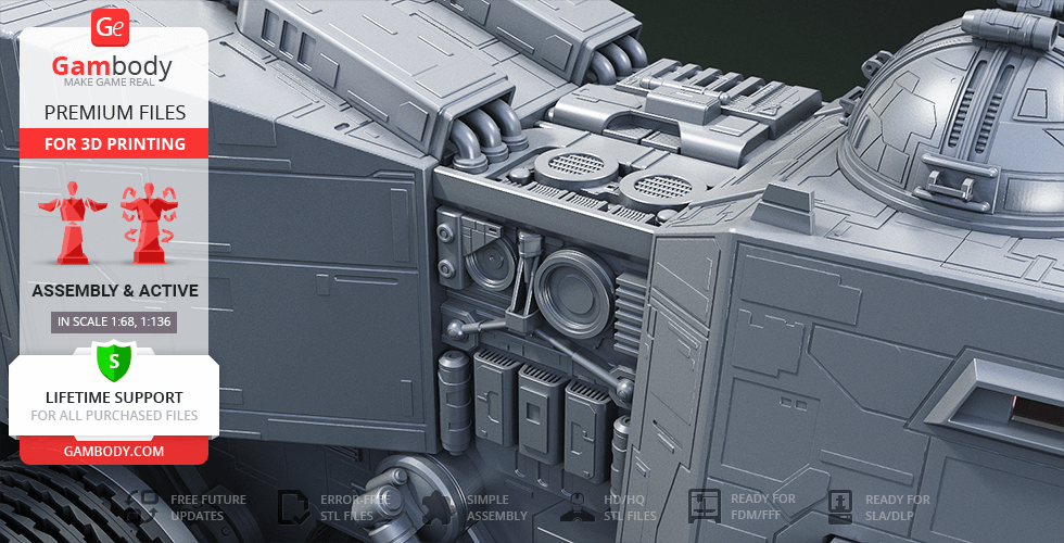
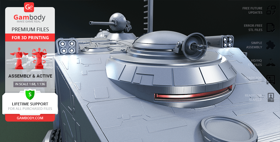
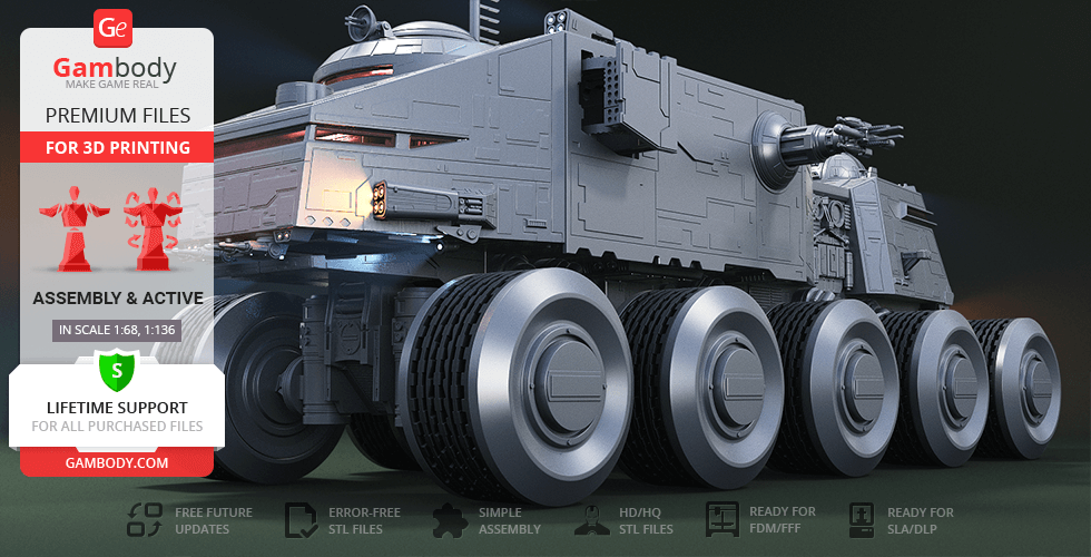
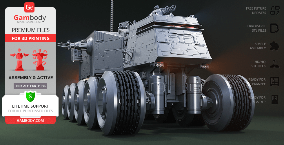
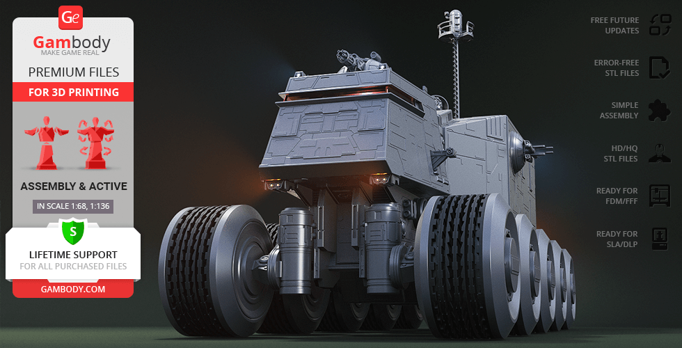
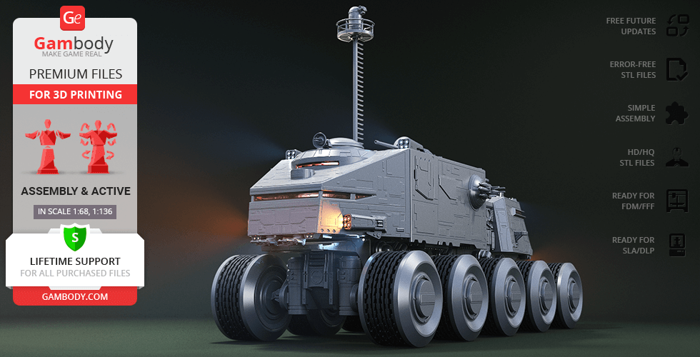
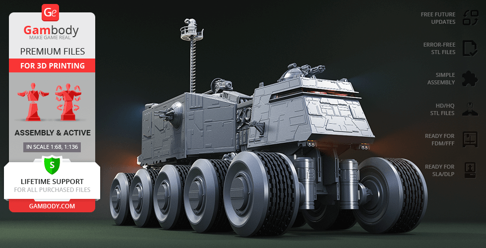
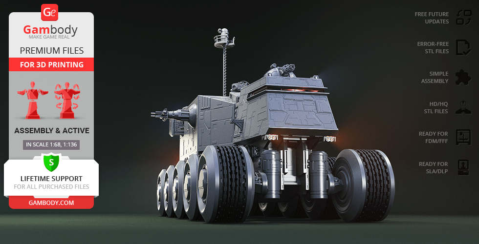
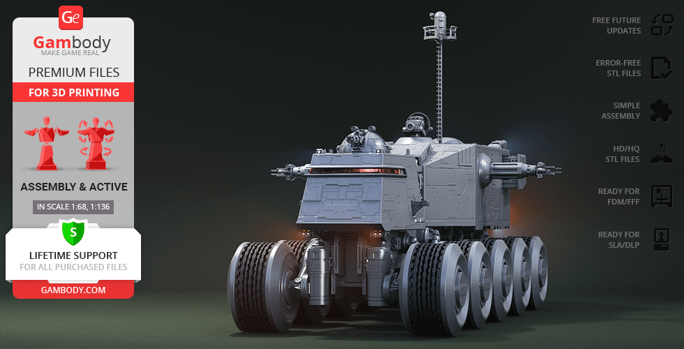
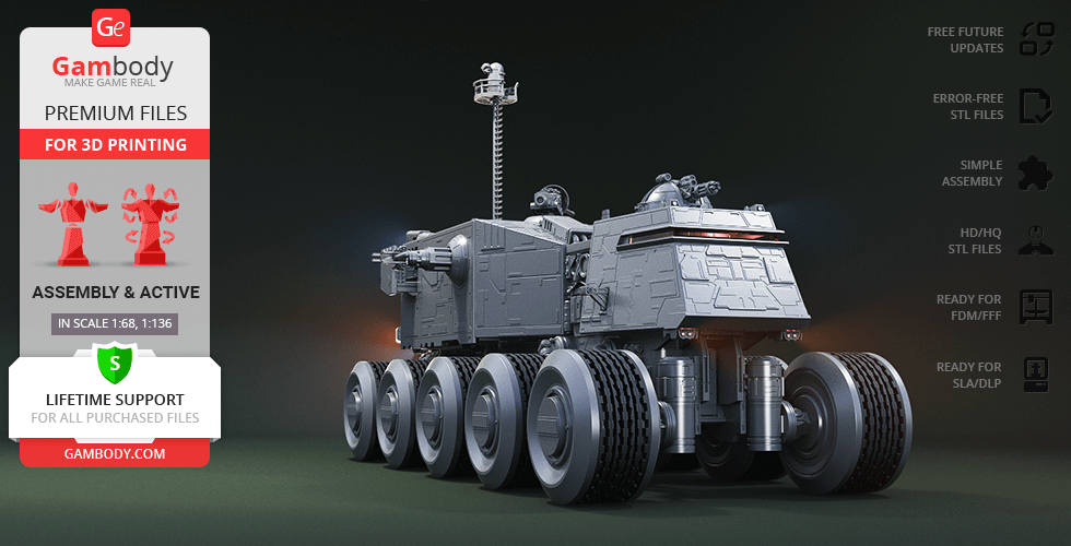
The HAVw A6 Juggernaut goes by many names, but we love to call it simply Juggernaut or turbo tank. This monstrous hunk of metal is an almost indestructible and definitely an irreplaceable unit not only in the Grand Army of the Republic but also in every Star Wars fan's collection. The iconic vehicle stole the hearts of many with its brutal mighty, unique built and the ability to manoeuvre with ease across any terrain. Juggernaut is equipped with top-notch technologies, tremendous firepower, and nearly impenetrable armour that can withstand enemy fire by absorbing it. Hosting up to 300 brave passengers and smaller support vehicles, it makes the unbreakable backbone of the clone armies. Inspired by this ominous war-machine, our contributing artist spent about 210 hours to recreate its vigour in the form of a 3D printing model and made sure it will be an exciting showpiece. The artist furnished the model with heavy laser cannon turret and rapid-repeating heavy laser cannon on the top of the tank for all-round defence. The antipersonnel laser cannons and grenade launchers on the sides of the battle machine will make sure to destroy every enemy coming your way no matter the distance. The tank can cruise along the shelves of your collection on its ten distinctive massive wheels, each segment of which is known to move independently to ensure smooth off-road navigation. Even the inside of the cockpits is adorned with comfy seats and control panels for your clone troopers to work at. Luckily, it won't take travelling all the way to the planet Kuat to obtain Juggernaut, all you'll need to do is launch your 3D printer and get down to engineering. With the help of the Gambody model for 3D printing, you will finally get the chance to try steering the legendary turbo tank and make the Separatist forces turn tail.
ADAPTATION FOR 3D PRINTING
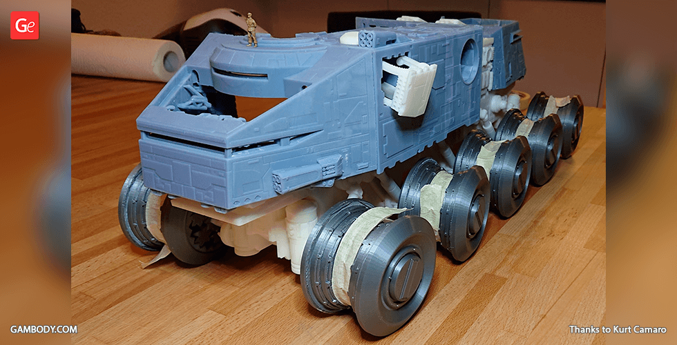
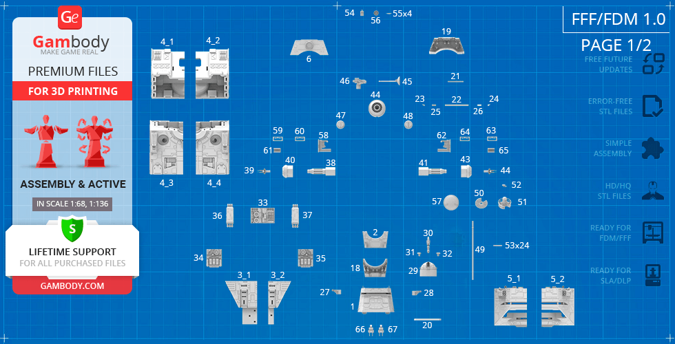
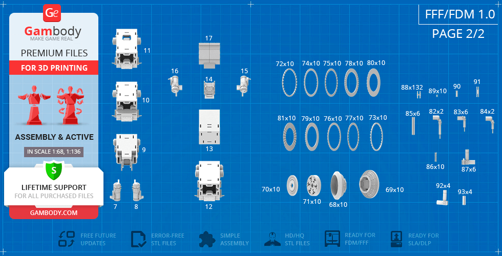
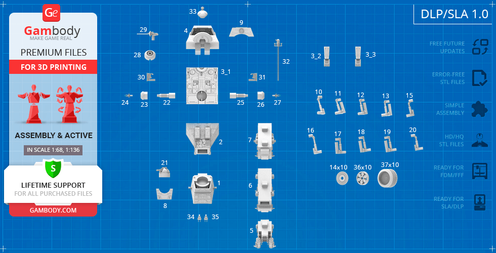
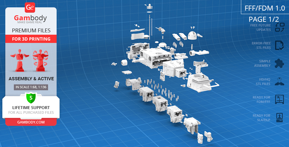
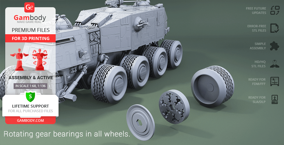
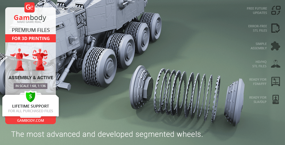
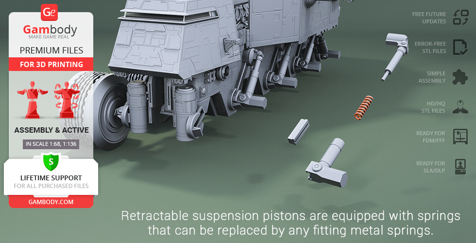
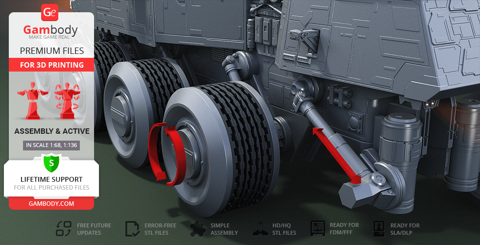
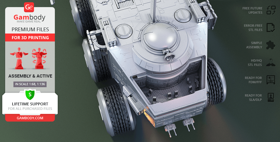
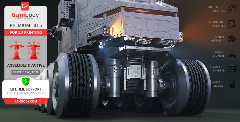
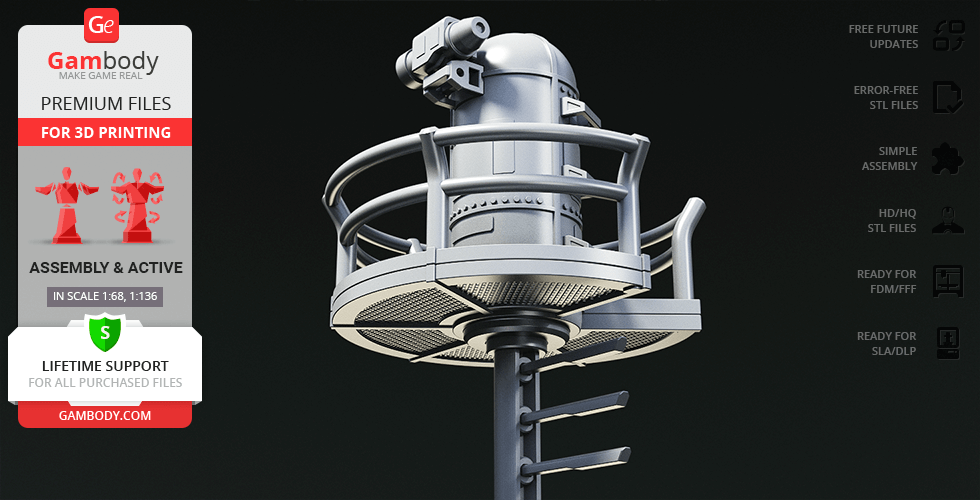
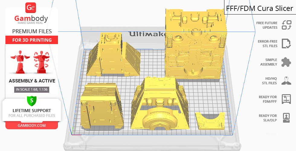
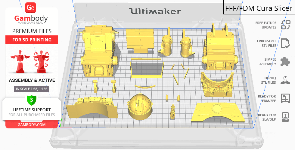
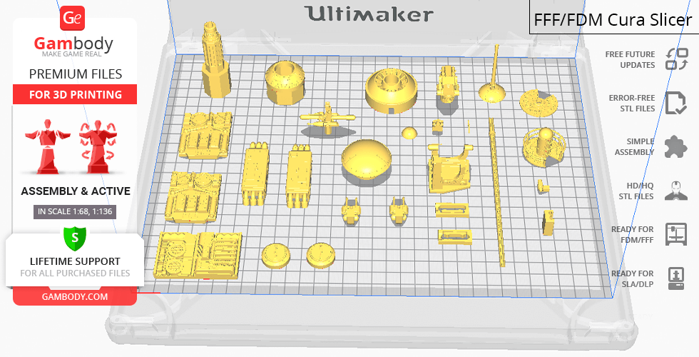
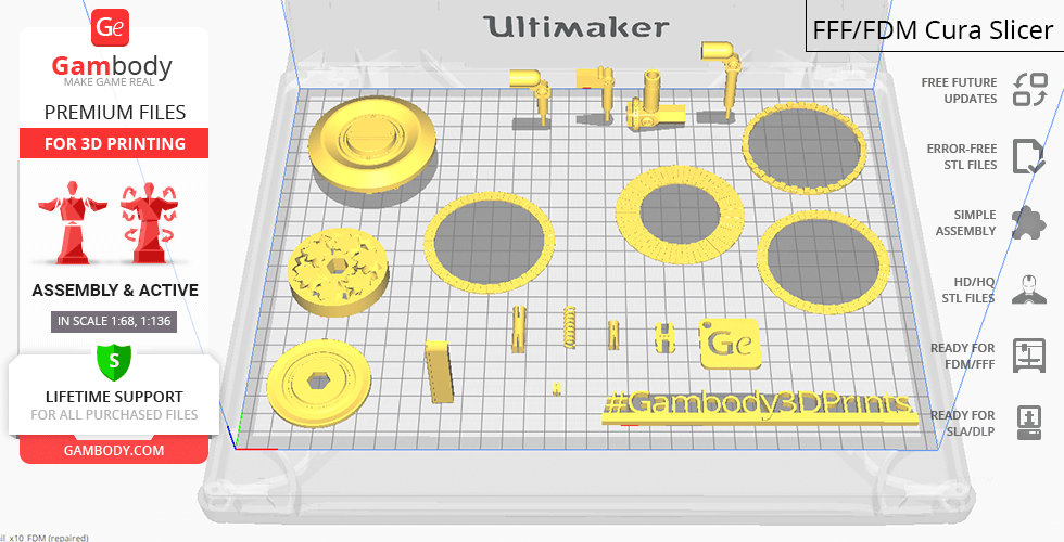
HAVw A6 Juggernaut is a highly-detailed assembly model and its moderation and adaptation for different types of 3D printers took Gambody team 76 hours in total. In order to stay true to the vehicle's massive size, the model was divided into as many assembly parts as needed to ensure that it will fit any 3D printer's build plate. The cutting of the model was chosen to ensure the cleanest 3D printing result possible and to minimise the amount of material needed to print the generated support, e.g. tank’s front twin blaster cannons, observation point, every single ladder rung, “jaw” that reveals the cannons, various hatches, etc. come as separate STL files. Additionally, the entire hull of the model in FFF/FDM 1.0 version, as well as some parts in DLP/SLA 1.0 and many parts in Eco version were made hollow to minimise the expenditure of material and time needed for printing. The windows to both cockpits were made into separate files to be printed in transparent PLA. The hatches of the cockpits can be taken off to showcase the highly-detailed interior. Various special mechanisms were introduced to ensure that the model has fully articulated elements in it: the sliding rails allow the antipersonnel laser cannons to extend from the hull, the upper heavy laser cannon turret rotates around the axis, and the rapid-repeating heavy laser cannon moves vertically, its gun can be fixed in two positions to match your battlefield installation perfectly. To ensure full mobility and independent movement of the ten wheels, each of them was equipped with rotating gear bearings and retractable suspension pistons, where the springs can be replaced with simple ball pen springs. The wheels themselves were divided into independent spinning segments to recreate the iconic all-terrain wheel system of the original vehicle. All assembly parts are provided in STL files in recommended positions that were worked out in order to ensure the smoothness of the details’ surfaces after printing and that the 3D printing beginners won't face difficulties when placing the parts on a build plate. When downloading any model's file you will also receive "Assembly Manual" for FFF/FDM 1.0 and DLP/SLA 1.0 versions in PDF format.
The model is saved in STL files, a format supported by most 3D printers. All STL files for 3D printing have been checked in Netfabb and no errors were shown.
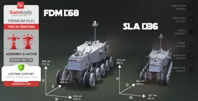
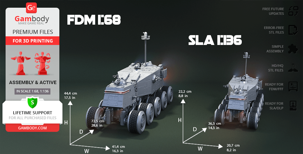
The model's scale was calculated from the actual length of HAVw A6 Juggernaut that is 49400 mm. The 3D printing model's chosen scale is 1/68 for the FFF/FDM version and 1/136 for the DLP/SLA/SLS versions.
VERSIONS' SPECIFICATIONS
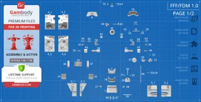
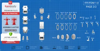
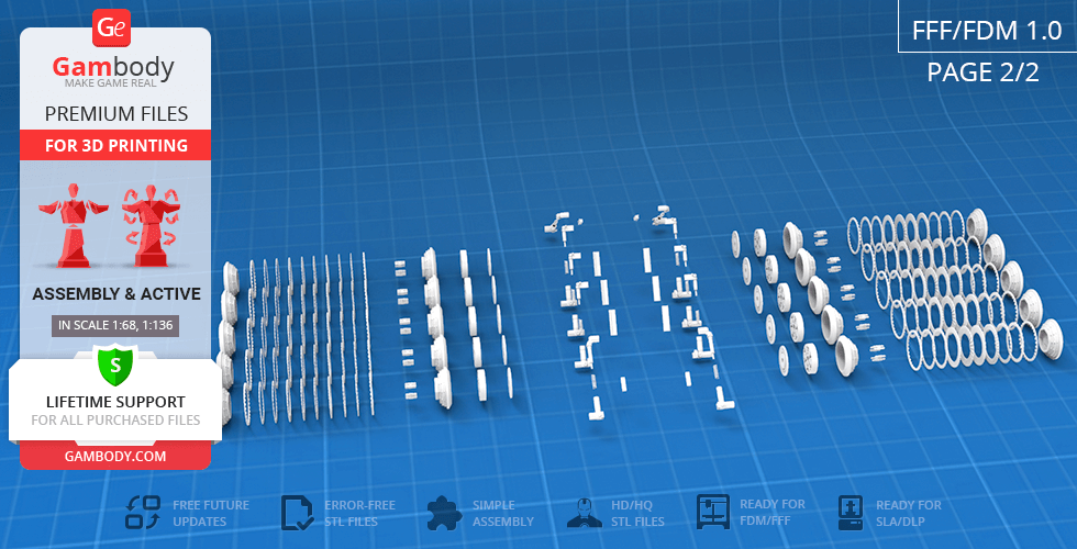
FFF/FDM 1.0 version features:
- Contains 98 parts;
- A printed model is 444 mm tall, 414 mm wide, 725 mm deep;
- Assembly kit includes lock 88_Ge_lock_10H_x151 to connect the model's parts securely without glue that needs to be printed 151 times;
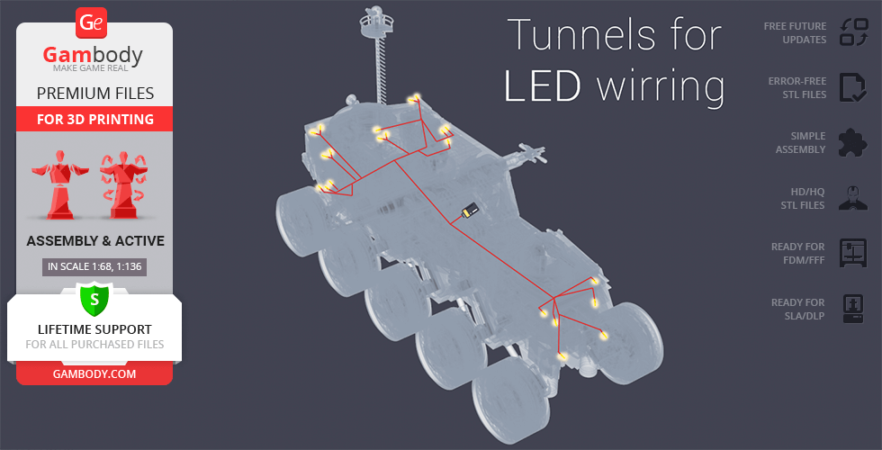
- The body of the tank is completely hollow and has tunnels for you to introduce LED wiring into all spotlights and viewports;
- Windows on the main and rear viewports are provided separately to be printed with the transparent filament;
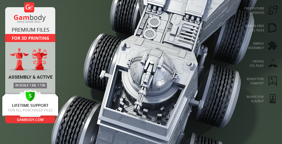
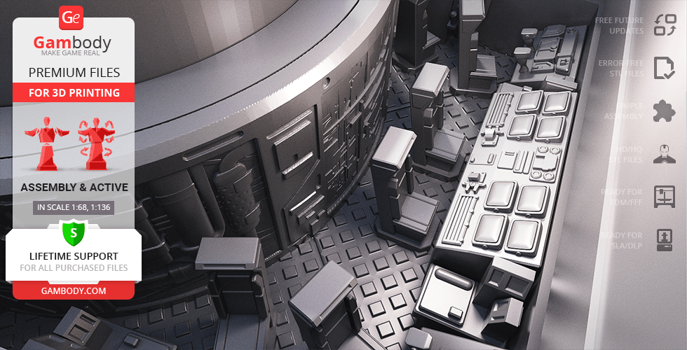
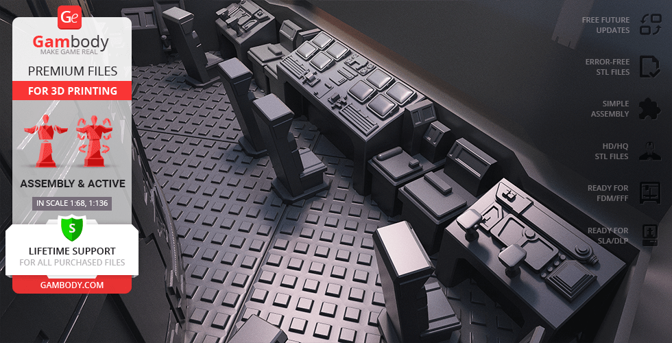
- Both smaller cockpit and commanding cockpit come with the highly-detailed interior;
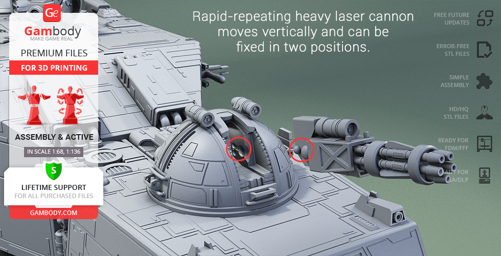
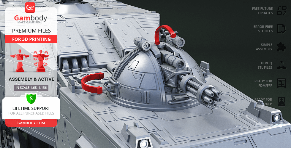
- Rapid-repeating heavy laser cannon rotates, moves vertically and can be fixed in two positions with the help of new mechanism;
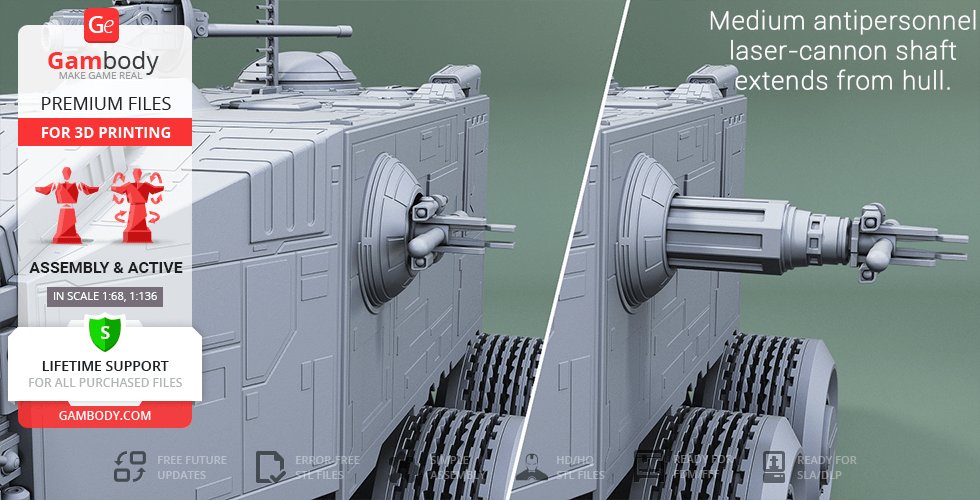
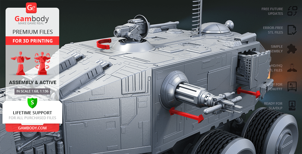
- Medium antipersonnel laser-cannon shaft extends from the hull; upper heavy laser cannon turret revolves on its axis;
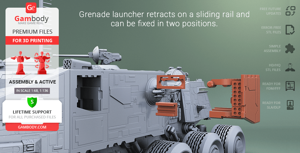
- Grenade launcher retracts on a sliding rail and can be fixed in two positions with the help of new mechanism;
- Retractable suspension pistons are equipped with springs that can be replaced by any fitting metal springs;
- There are rotating gear bearings in all highly developed segmented wheels;
- All parts are divided in such a way that you will print them with the smallest number of support structures.
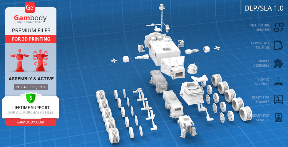
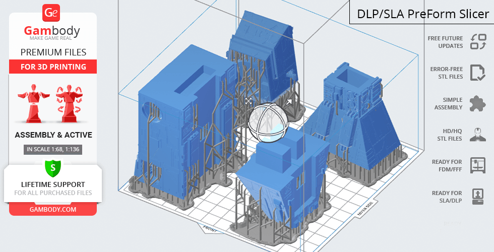
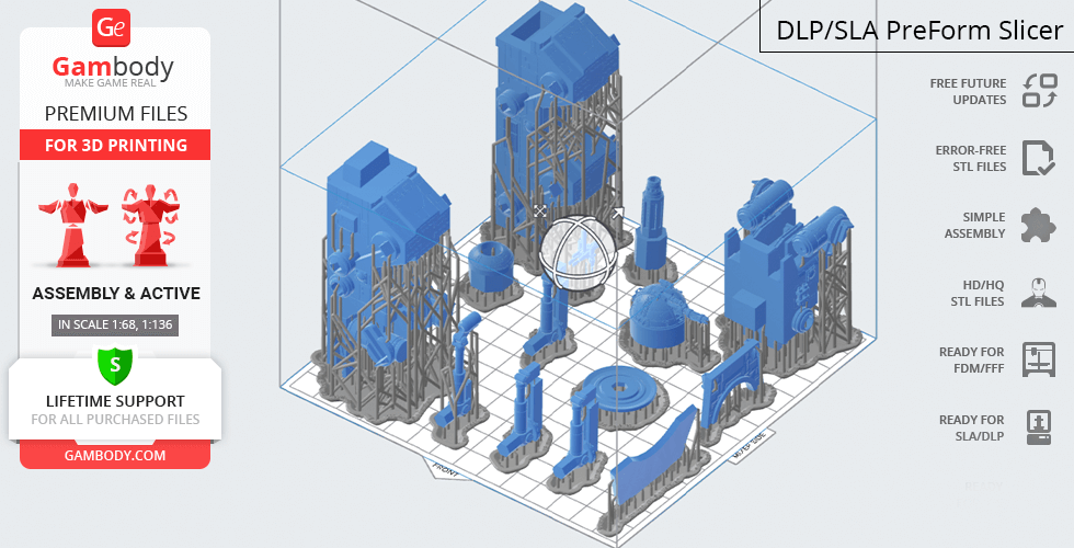
DLP/SLA 1.0 version features:
- Contains 39 parts;
- A printed model is 222 mm tall, 207 mm wide, 363 mm deep;
- Rapid-repeating heavy laser cannon rotates, moves vertically and can be fixed in two positions with the help of new mechanism;
- Medium antipersonnel laser-cannon shaft extends from the hull; upper heavy laser cannon turret revolves on its axis;
- Grenade launcher retracts on a sliding rail and can be fixed in two positions with the help of new mechanism;
- Both smaller cockpit and commanding cockpit come with the highly-detailed interior;
- There are rotating gear bearings in all ten wheels;
- All parts are divided in such a way to fit the build plates and to ensure that support structures are generated where needed.
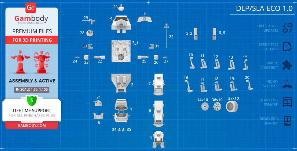
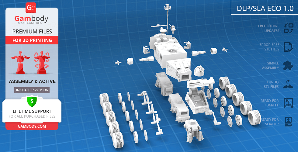
DLP/SLA Eco 1.0 version features:
- Contains 39 parts;
- A printed model is 222 mm tall, 207 mm wide, 363 mm deep;
- Rapid-repeating heavy laser cannon rotates, moves vertically and can be fixed in two positions with the help of new mechanism;
- Medium antipersonnel laser-cannon shaft extends from the hull; upper heavy laser cannon turret revolves on its axis;
- Grenade launcher retracts on a sliding rail and can be fixed in two positions with the help of new mechanism;
- Both smaller cockpit and commanding cockpit come with the highly-detailed interior;
- There are rotating gear bearings in all ten wheels;
- Contains some hollowed out parts to save resin.
WHAT WILL YOU GET AFTER PURCHASE?
- STL files of Juggernaut Turbo Tank Model for 3D printing which consist of 176 parts;
- 3 versions of files for this model for FFF/FDM and DLP/SLA/SLS printers;
- High-poly detailed model of Juggernaut Turbo Tank;
- Assembly Manual for FFF/FDM 1.0 and DLP/SLA/SLS 1.0 versions in PDF format;
- Detailed settings that we provide as a recommendation for Cura , Simplify3D and Slic3r for the best print;
- Full technical support from the Gambody Support Team.
You can get the model of Juggernaut Turbo Tank for 3D Printing immediately after the purchase! Just click the green Buy button in the top-right corner of the model’s page. You can pay with PayPal or your credit card.
Watch the tutorial on how to assemble Juggernaut Turbo Tank 3D Printing Model at Gambody YouTube channel.
Also, you may like other Star Wars 3D Printing Models.
_______
FAQ:
Where can I print a model if I have no printer?
How to get started with 3D printing?
How to set up my 3D printer?
How to choose right 3D model print bed positioning?
How to paint printed figurine?
Average customer rating (10 reviews)
3.9
Ratings breakdown
Click a star rating to filter reviews
Overall experience
Level of detail in the model
3.9
Model cut quality and assembly guide
3.9
Clarity and accuracy of the model page
3.9
Level of detail in the model
3
Model cut quality and assembly guide
3
Clarity and accuracy of the model page
3
Level of detail in the model
5
Model cut quality and assembly guide
5
Clarity and accuracy of the model page
5
Level of detail in the model
4
Model cut quality and assembly guide
4
Clarity and accuracy of the model page
4
Level of detail in the model
1
Model cut quality and assembly guide
1
Clarity and accuracy of the model page
1
Level of detail in the model
5
Model cut quality and assembly guide
5
Clarity and accuracy of the model page
5
Level of detail in the model
5
Model cut quality and assembly guide
5
Clarity and accuracy of the model page
5
Level of detail in the model
2
Model cut quality and assembly guide
2
Clarity and accuracy of the model page
2
Level of detail in the model
4
Model cut quality and assembly guide
4
Clarity and accuracy of the model page
4
Level of detail in the model
5
Model cut quality and assembly guide
5
Clarity and accuracy of the model page
5
Level of detail in the model
5
Model cut quality and assembly guide
5
Clarity and accuracy of the model page
5
Below you'll find detailed slicing settings for Bambu Studio 2.0+, Orca Slicer 2.0+, UltiMaker Cura 5.0+, PrusaSlicer 2.0+, Slic3r 1.3+, Simplify3D 5.0+ to help you get the best results when printing this model. These settings are optimized specifically for this 3D model, but please note they may need slight adjustments depending on your printer or filament. When in doubt, refer to your printer's user manual.
To avoid printing issues and achieve the best quality, we highly recommend applying the following settings:
For better quality use 0.12 mm layer height, for fast printing use 0.2 mm layer height. For pins and the Ge connectors, use 0.2 layer height.
120-150% of your Layer Height
But you can paint the seam if you want.
You have to calibrate this parameter
You have to calibrate this parameter
You have to calibrate this parameter
For pins and power elements of the structure, such as the vehicle frame, use 3 loop
Disabled for vehicles and enabled for characters
For 0,2 Layer Height
The parameters in this tab vary greatly, it all depends on the quality of your printer. For example, if you have a classic Ender3, stick to the minimum parameters, but if you have a newer printer, for example Anycubic cobra 3 v2, you can select the maximum recommended values
Settings for advanced users, change these parameters only if you have sufficient 3D printing expertise
Enable this parameter if your model requires supports
We also recommend placing and removing supports manually in some places using special button
1-2 loops for more thick support
Top Z distance = 1-1.3 layer Height. If the supports are hard to remove, try increasing this setting by 0.1-0,4 mm
Bottom Z distance = 1-1.3 layer Height. If the supports are hard to remove, try increasing this setting by 0.1-0,4 mm
You have to calibrate this parameter which one is better for your filament
Increase this parameter if the supports are hard to remove from walls
For PLA and PETG filament types
5-8 mm is optional for small prints that have bad adhesion to the build plate
You have to calibrate this parameter
Read the description on your filament roll
Read the description on your filament roll and increase this parameter for fast printers
Read the description on your filament roll and increase this parameter for fast printers
For better quality use 0.12 mm layer height, for fast printing use 0.2 mm layer height. For pins and the Ge connectors, use 0.2 layer height.
120-150% of your Layer Height
But you can paint the seam if you want.
0.01-0.05 You have to calibrate this parameter
0.01-0.05 You have to calibrate this parameter
0.1-0.2 You have to calibrate this parameter
For pins and power elements of the structure, such as the vehicle frame, use 3 loop
Disabled for vehicles and ships, enabled for characters
For 0,2 Layer Height
For 0,2 Layer Height
The parameters in this tab vary greatly, it all depends on the quality of your printer. For example, if you have a classic Ender3, stick to the minimum parameters, but if you have a newer printer, for example, Anycubic Kobra 3 Or Bambulab A1, you can select the maximum recommended values.
Settings for advanced users, change these parameters only if you have sufficient 3D printing expertise
Enable this parameter if your model requires supports
We also recommend placing and removing supports manually in some places using special button
Top Z distance = 1-1.3 layer Height. If the supports are hard to remove, try increasing this setting by 0.1-0,4 mm
Bottom Z distance = 1-1.3 layer Height. If the supports are hard to remove, try increasing this setting by 0.1-0,4 mm
Increase this parameter if the supports are hard to remove from walls
For PLA and PETG filament types
5-8 mm is optional for small prints that have bad adhesion to the build plate
Read the description on your filament roll
Read the description on your filament roll and increase this parameter for fast printers
You have to calibrate this parameter
Read the description on your filament roll and increase this parameter for fast printers
Read the description on your filament roll
This field is filled in according to your printer specifications when you add it to the slicer.
You can add custom G-code here for the start and end of the print. However, be careful - this is for advanced users only!
You have to calibrate your printer using Ge retraction test models
Retraction Length: For direct-drive setups use 0.5 mm to 2.5 mm; for Bowden extruders use 5 to 7 mm
This is how fast the filament is pulled back—40-60 mm/s for direct drive and 30-50 mm/s for Bowden setups.
You have to calibrate this parameter: Reduce it until the printer starts to hit the parts with the nozzle during printing, then increase it by 0.2.
For better quality use 0.12 mm layer height, for fast printing use 0.2 mm layer height. For pins and the Ge connectors, use 0.2 layer height.
120-150% of your Layer Height
To increase the strength of the print parts, use wall line count: 3
For pins and connectors use 50% Infill
These parameters are for standard PLA plastic. If you are using a different type of plastic, check the printing temperature recommended by the manufacturer. Also, read the description on your filament spool. For fast printers, add +30 °C to the current parameters.
The parameters in this tab vary greatly, it all depends on the quality of your printer. For example, if you have a classic Ender3, stick to the minimum parameters, but if you have a newer printer, for example Anycubic cobra 3 v3, you can select the maximum recommended values
Settings for advanced users, change these parameters only if you have sufficient 3D printing expertise.
You need to calibrate this parameter using Gambody test models. These values are average values for a Direct Drive extruder; for a Bowden extruder, the values should be increased.
You need to calibrate this parameter using Gambody test models. These values are average values for a Direct Drive extruder; for a Bowden extruder, the values should be increased.
Use this value other than 0 if your nozzle catches on the internal infill during travel moves. Try to keep this value as low as possible in height.
Use normal supports to support large, straight surfaces (most mechanical or technical parts).
You have to calibrate this parameter according to the capabilities of your printer and your filament, using a Gambody test models.
Use 1 instead of 0 if your supports are thin and tall. They will be harder to remove, but much stronger.
Top Z distance = 1-1.3 layer Height. If the supports are hard to remove, try increasing this setting by 0.1-0,4 mm
Increase this parameter if the supports are hard to remove from walls
Use tree supports to support complex objects, such as characters.
You have to calibrate this parameter according to the capabilities of your printer and your filament, using a Gambody test models.
Top Z distance = 1-1.3 layer Height. If the supports are hard to remove, try increasing this setting by 0.1-0,4 mm
Increase this parameter if the supports are hard to remove from walls
Use a skirt for all parts when printing on outdated printers.
Use a brim when printing thin but tall parts, as well as parts with a small bed adhesion area.
For better quality use 0.12 mm layer height, for fast printing use 0.2 mm layer height. For pins and the Ge connectors, use 0.2 layer height.
120-150% of your Layer Height
for 0.2 Layer Height
But you can paint the seam if you want.
(for PLA and PETG)
(5-8 mm is optional for small prints that have bad adhesion to the build plate)
Enable this parameter if your model requires supports
(45-50 degree)You have to calibrate this parameter according to the capabilities of your printer
and your filament, using a Gambody test models.
Top contact Z distance = 1-1.3 layer Height. If the supports are hard to remove, try
increasing this setting by 0.1-0,4 mm
Top contact Z distance = 1-1.3 layer Height. If the supports are hard to remove, try
increasing this setting by 0.1-0,4 mm
Increase this parameter if the supports are hard to remove from walls
The parameters in this tab vary greatly, it all depends on the quality of your printer. For example, if you have a classic Ender3, stick to the minimum parameters, but if you have a newer printer, for example Anycubic cobra 3 v3, you can select the maximum recommended values
Settings for advanced users, change these parameters only if you have sufficient 3D printing expertise. Use the minimum value for outdated printers without acceleration calibration, and the maximum value for modern printers if you need it.
These settings only work for 3D printers with multiple extruders
You can try setting all parameters in this section, except the First layer, to values between 0.75% of your nozzle diameter and 1.25% of your nozzle diameter. Adjusting them will help you work out the optimal parameters for the best quality for your print. As for the First layer, you can set it to 150% of the diameter of your nozzle for better adhesion to the build plate (for a nozzle with a diameter of 0.4 mm, the First layer extrusion width can be from 0.3 mm to 0.5 mm)
For better printing quality you have to calibrate this parameter using Gambody test model.
Check your filament manufacturer's temperature recommendations on the spool.
Cooling parameters depends on the material you use for printing.
*for PLA
For better quality use 0.12 mm layer height, for fast printing use 0.2 mm layer height. For pins and the Ge connectors, use 0.2 layer height.
120-150% of your Layer Height
For 0.12 Layer Height
For 0.12 Layer Height
For pins and connectors use 50% Infill
Use skirt for outdated 3d printers
(5-8 mm is optional for small prints that have bad adhesion to the build plate)
Enable this parameter if your model requires supports
(45-60 degree)You have to calibrate this parameter according to the capabilities of your printer and your filament, using a Gambody test models
Contact Z distance = 1-1.3 layer Height. If the supports are hard to remove, try increasing this setting by 0.1-0,4 mm
The parameters in this tab vary greatly, it all depends on the quality of your printer. For example, if you have a classic Ender3, stick to the minimum parameters, but if you have a newer printer, for example Anycubic cobra 3 v3, you can select the maximum recommended values
Settings for advanced users, change these parameters only if you have sufficient 3D printing expertise. Use the minimum value for outdated printers without acceleration calibration, and the maximum value for modern printers if you need it.
You have to calibrate this parameter from 0.9 to 1.1 according to the capabilities of your printer and your filament, using a Gambody test models.
Check your filament manufacturer's temperature recommendations on the spool.
Cooling parameters depends on the material you use for printing.
Calibrate this value if you need to reduce or improve the adhesion between the plastic and the heat bed
Your current nozzle diameter
You need to calibrate this parameter using Gambody test models. These values are average values for a Direct Drive extruder; for a Bowden extruder, the values should be increased.
Your current nozzle diameter
You have to calibrate this parameter using Gambody test models.
You need to calibrate this parameter using Gambody test models. These values are average values for a Direct Drive extruder; for a Bowden extruder, the values should be increased.
For better quality use 0.12 mm layer height, for fast printing use 0.2 mm layer height. For pins and the Ge connectors, use 0.2 layer height.
For 0,2 Layer Height
For 0,2 Layer Height
To increase the strength of the print parts, use Outline Perimeters: 3
You can enable this parameter to print rounded or spherical models, as well as character models.
Use this option only if your parts are too tight. but better calibrate your printer extrusion
Use this option only if your parts are too tight. but better calibrate your printer extrusion
Use 2 and more if you want to create skirt instead brim
1-2 for skirt and 10-20 for brim
Use for wipe nozzle if you need
Use For ABS filament
For pins and connectors use 50% Infill
Top Z distance = 1-1.3 layer Height. If the supports are hard to remove, try increasing this setting by 0.1-0,4 mm
Calibrate your filament and detect optimal temperature for it
Average temperature for PLA filament
The parameters in this tab vary greatly, it all depends on the quality of your printer. For example, if you have a classic Ender3, stick to the minimum parameters, but if you have a newer printer, for example Anycubic cobra 3 v3, you can select the maximum recommended values
Settings for advanced users, change these parameters only if you have sufficient 3D printing expertise.