


Files
3D model format
Stereolithography (.stl)
Total files
Slicer settings
Mesh error check
Netfabb
Support
Lifetime support from Gambody team
Update requests
Available to verified buyers
Model complexity
Advanced: may require tuning print settings or support placement, plus precise fitting, gluing, or sanding.
Model versions
FFF/FDM
Assembly method
not specified
Features
DLP/SLA
Assembly method
not specified
Features
Additional details
Part of diorama
No
Special pack included
No
You will get instant access to the STL files of Jules Verne Train Locomotive 3D Printing Model | Assembly + Action after completing your purchase. Simply add the model to your cart and check out using PayPal, credit or debit card, Apple Pay, Google Pay, Alipay, or other available payment methods.
Watch the assembly video for Jules Verne Train Locomotive 3D Printing Model | Assembly + Action, and explore more tutorials, behind-the-scenes content, 3D printing timelapses, and painting guides on the official Gambody YouTube channel.
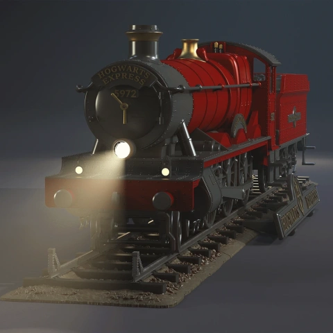
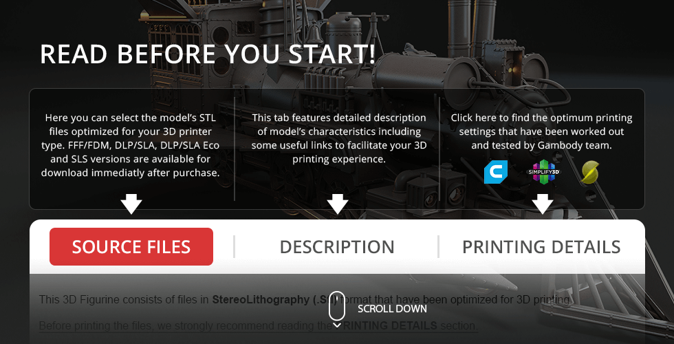
This 3D Model of Jules Verne Train Locomotive from Back to the Future Part III consists of files in StereoLithography (.Stl) format that is optimized for 3D printing.
Before printing the files, we strongly recommend reading the PRINTING DETAILS section.
WHAT WILL YOU GET AFTER PURCHASE?
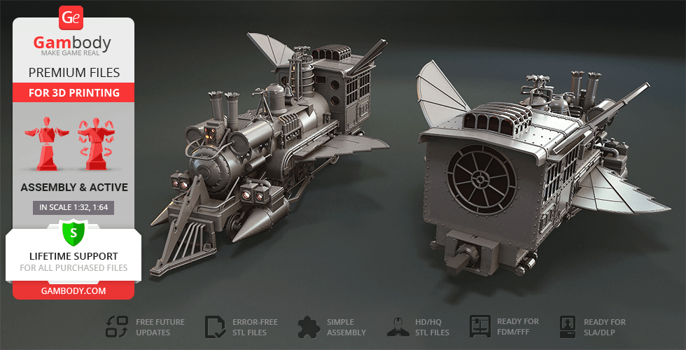
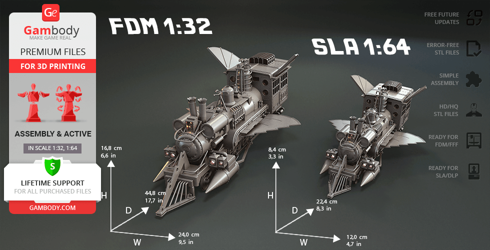
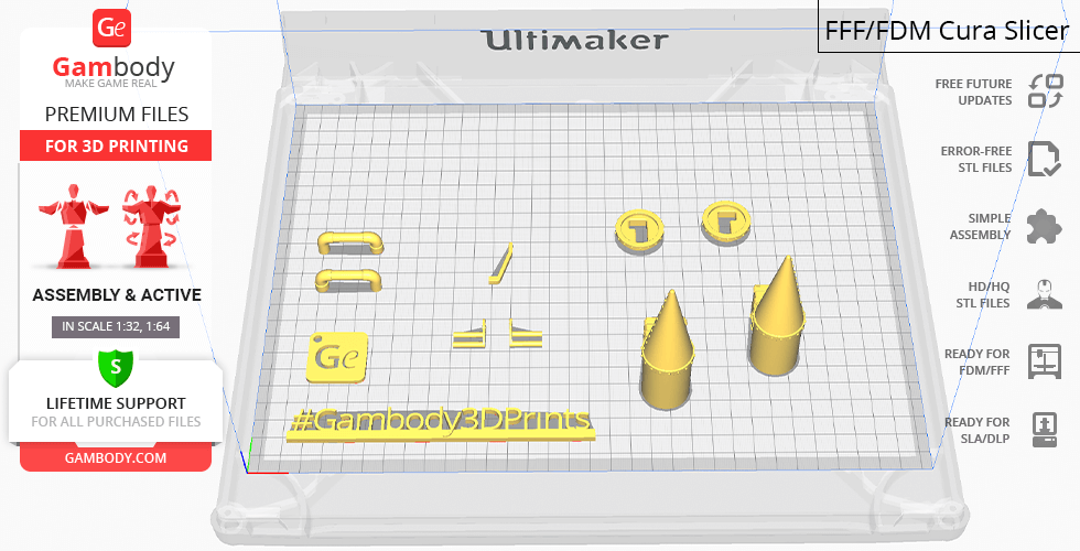
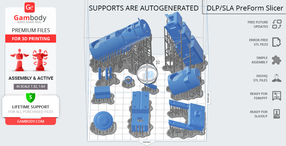
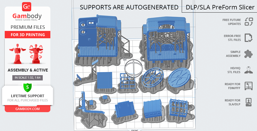
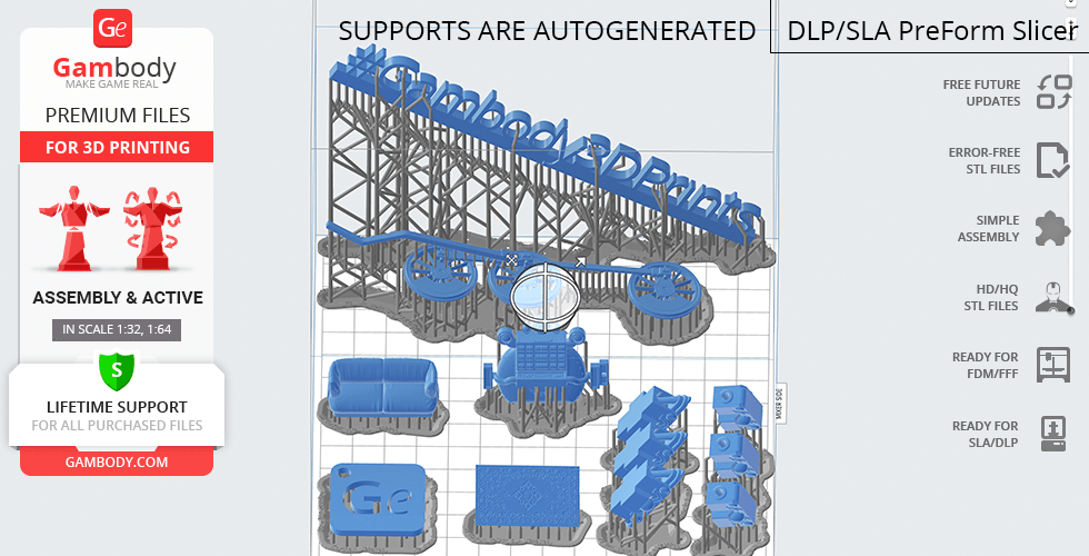
- 2 versions of Jules Verne Train Locomotive STL files for FFF/FDM and DLP/SLA/SLS - files for both versions are available for download after the purchase
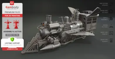
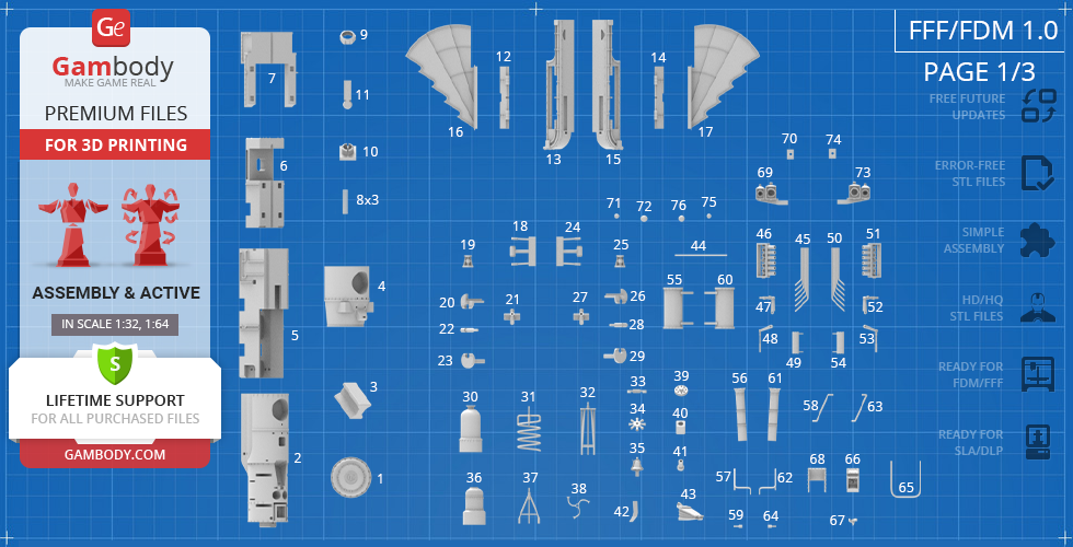
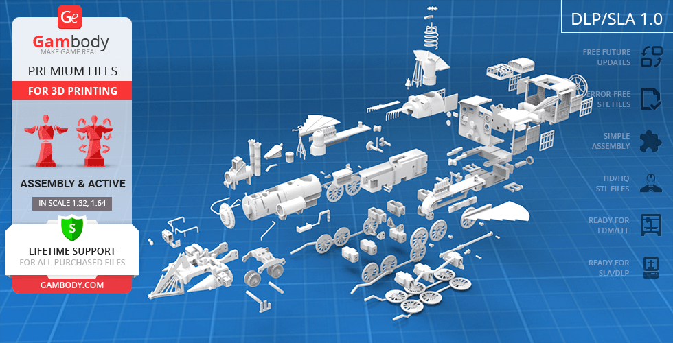
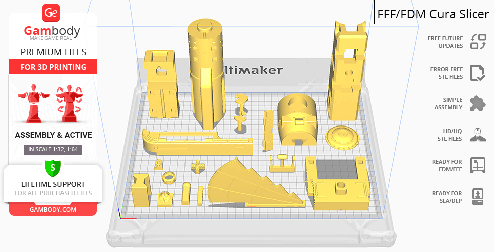
- STL files of high-poly Jules Verne Train Locomotive 3D Model for 3D printing consist of 212 parts
- Sizes:
FFF/FDM: 168 mm tall, 240 mm wide, 448 mm deep
DLP/SLA/SLS: 84 mm tall, 120 mm wide, 224 mm deep
- Assembly Manual for FFF/FDM 1.0 and DLP/SLA/SLS 1.0 versions in PDF format
- Detailed settings that we provide as a recommendation for Cura, Simplify3D and Slic3r for the best print
- Full technical support from the Gambody Support Team
Detailed information about this 3D printing model is available in the DESCRIPTION section.
Before printing, take a look at Printing Details for recommended settings and tips to achieve better results.
ABOUT THIS 3D MODEL
Great Scott! Are you telling me that you made a 3D printing model… out of a Jules Verne Train Locomotive?!
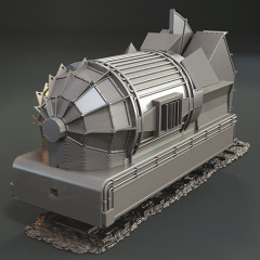
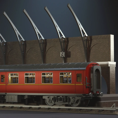
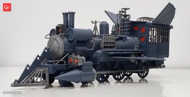
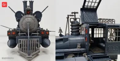
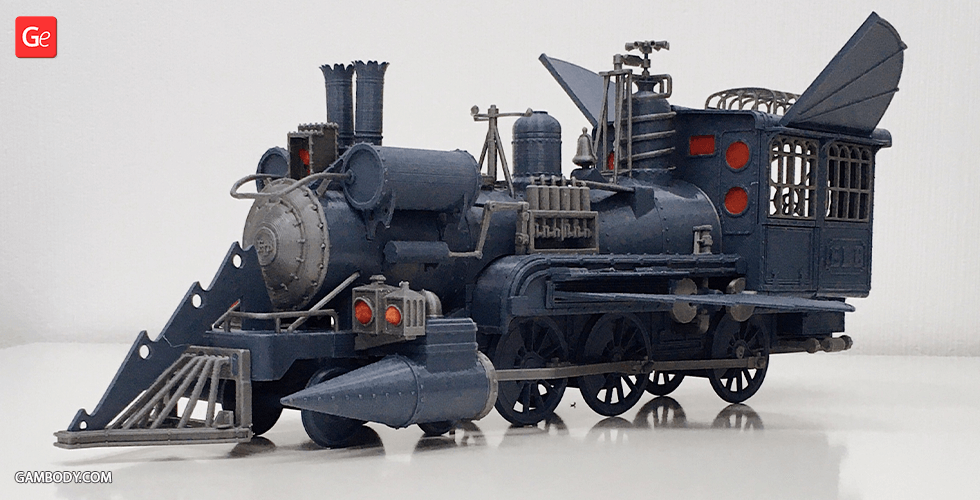
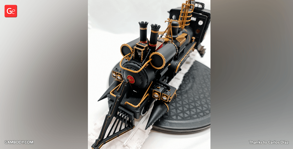
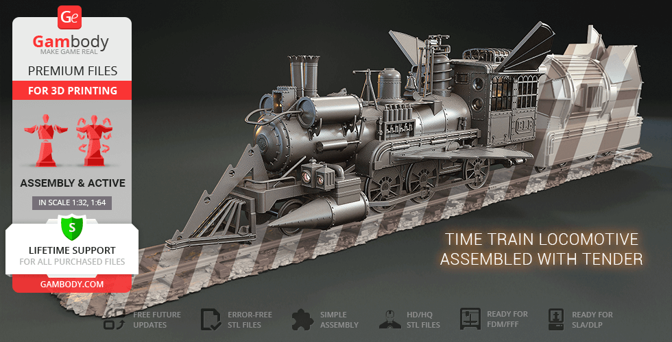
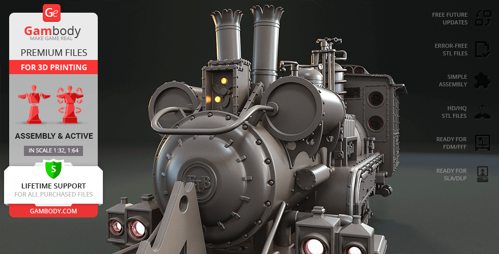
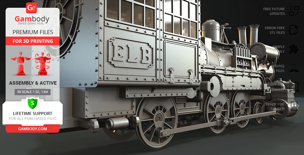
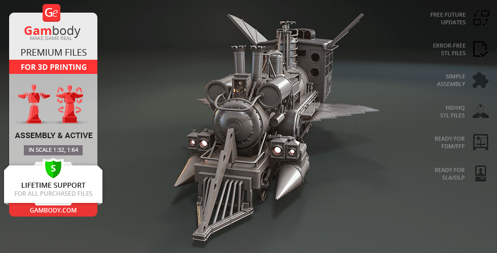
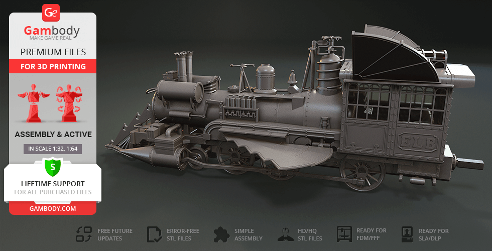
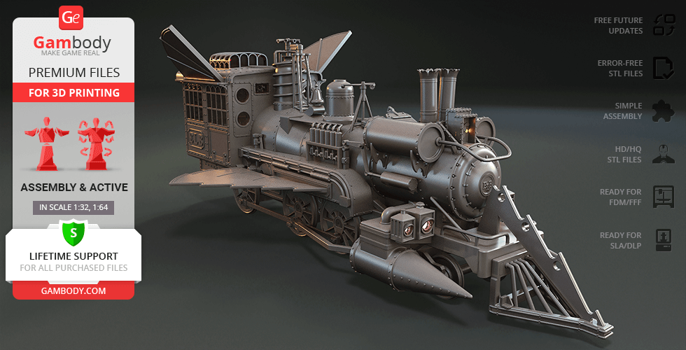
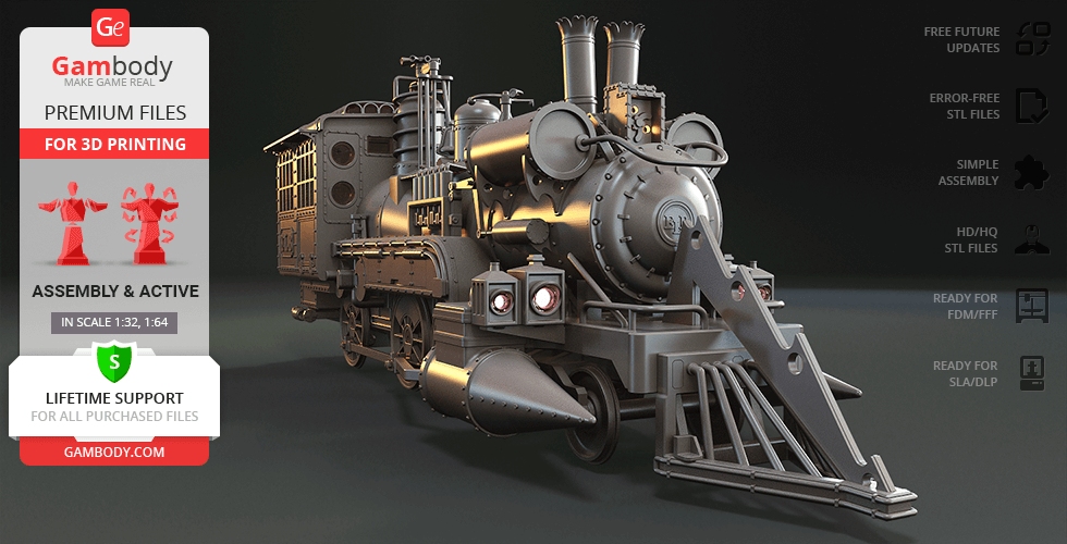
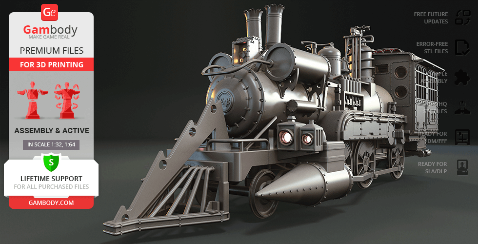
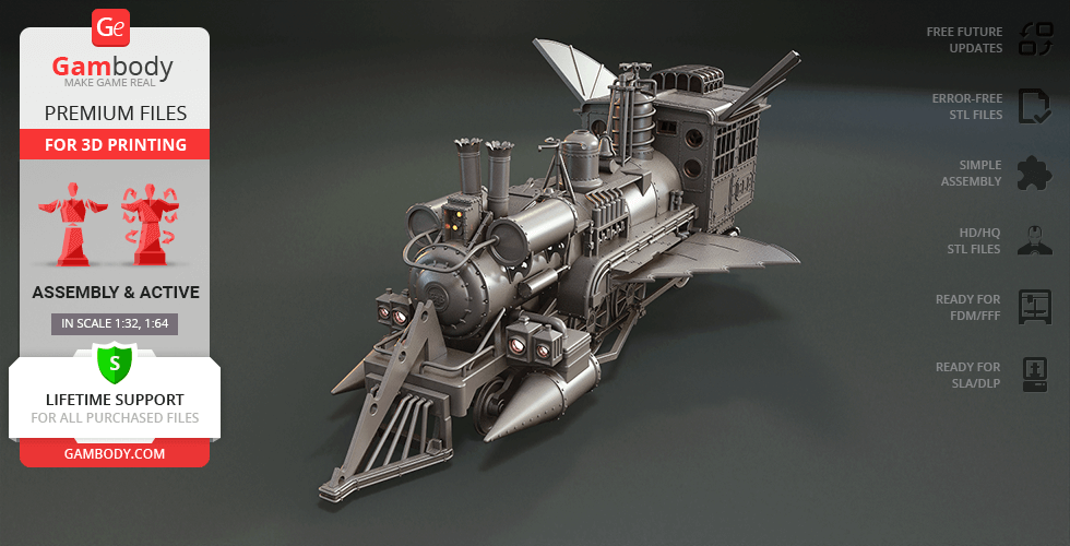
In the finale of the western-themed Back to the Future Part III Doc Brown introduces Marty and Jennifer to his new family including his wife and sons Jules and Verne. As one would obviously expect, the Browns choose to arrive riding the most unusual of vehicles - a Jules Verne-themed time-travelling train! The “Hollywood star locomotive”, namely the archetypal 19th century USA steam locomotive Sierra Railway No. 3 was chosen to embody Doc’s ultimate invention that we are now happy to feature in Gambody’s time-travelling category!
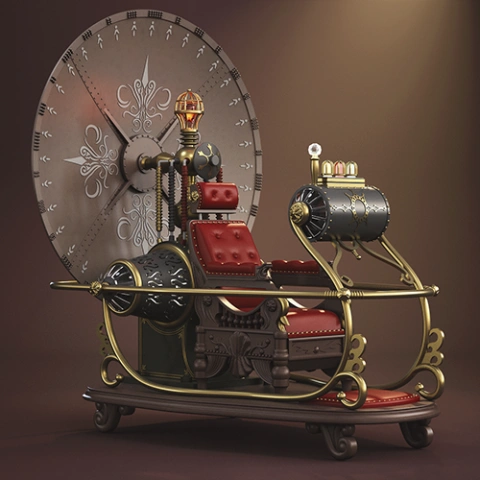
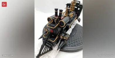
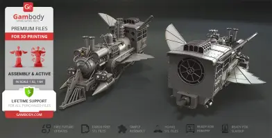
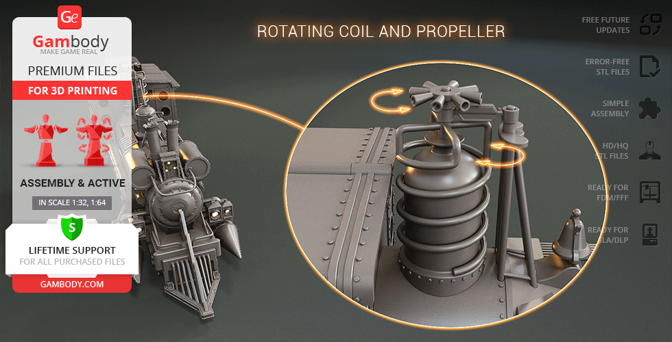
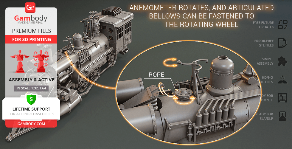
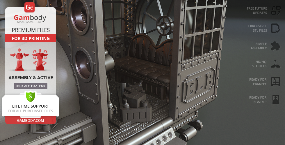
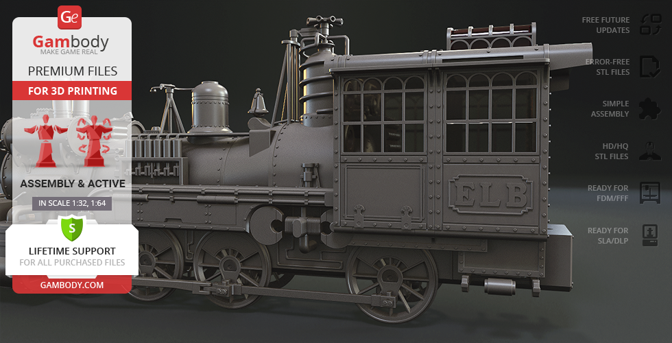
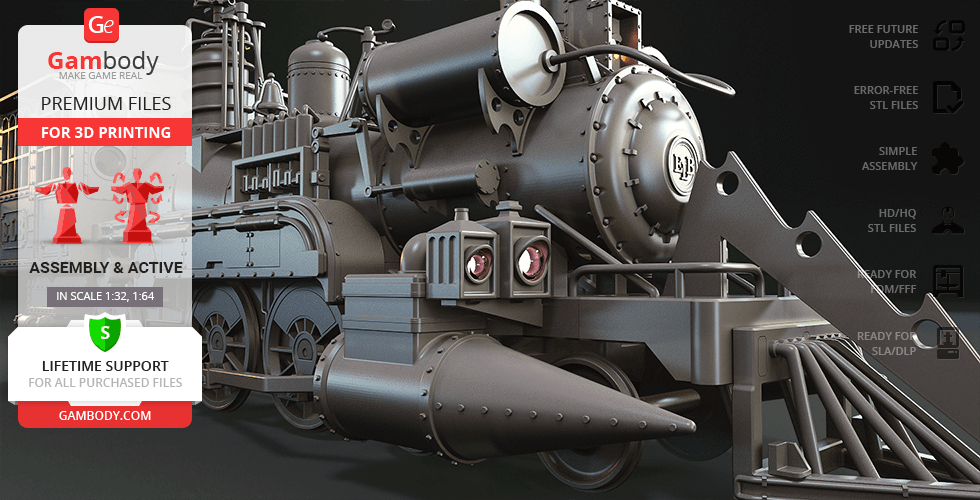
By using the components of THE hoverboard from 2015, and his extensive scientific knowledge and experience, Doc equipped a steam locomotive with a flux capacitor that was able to store loads of jigowatts required for time travel. Inspired by a “steampunky” retrofuturistic nature of the Jules Verne locomotive, our contributing 3D artist prepared an exquisite 3D printing Time Train worthy of joining any collection! The Train Time Machine sports two pairs of wings, rotating coil, propeller, and anemometer, and of course "ELB" logo on each side after train’s creator Emmett Lathrop Brown.
ADAPTATION FOR 3D PRINTING
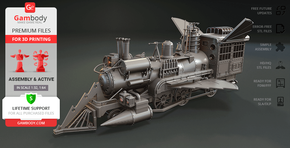
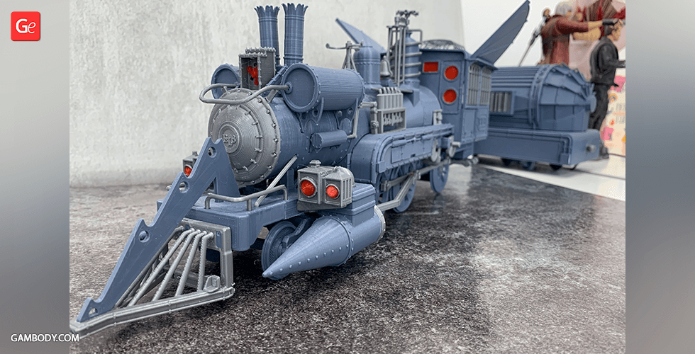
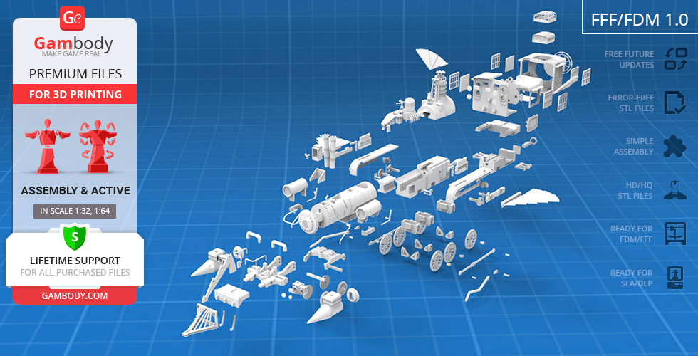
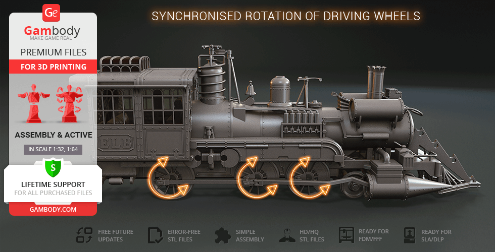
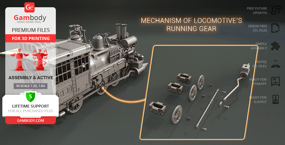
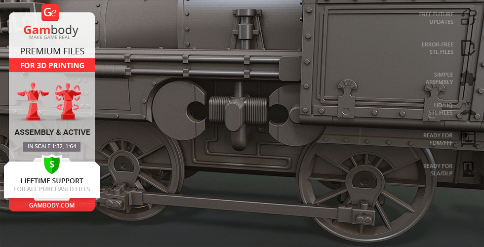
Jules Verne Train Locomotive 3D printing model is a highly detailed assembly model and its moderation and adaptation for different types of 3D printers took Gambody team 120 hours in total. In order to preserve the accurate likeness of the original Sierra No. 3 ‘The Movie Star locomotive’ as well as the modified movie Jules Verne “ELB” Train, the model was divided into many parts that are to be assembled as if a real locomotive. Taking into account the willingness of our customers to make their 3D printing projects as true to life as possible, Gambody team worked on the highly-articulated assembly of the locomotive that presupposes active runninggear and a variety of movable elements.
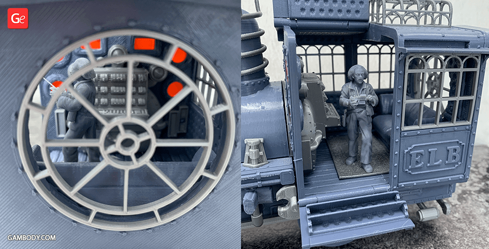
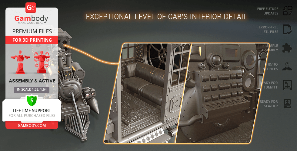
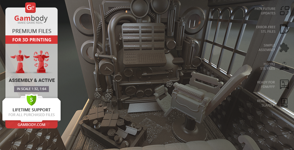
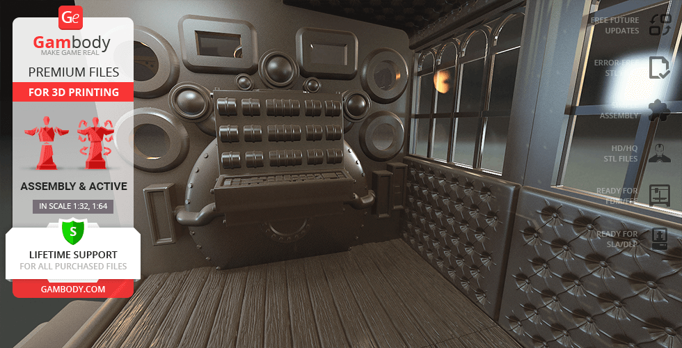
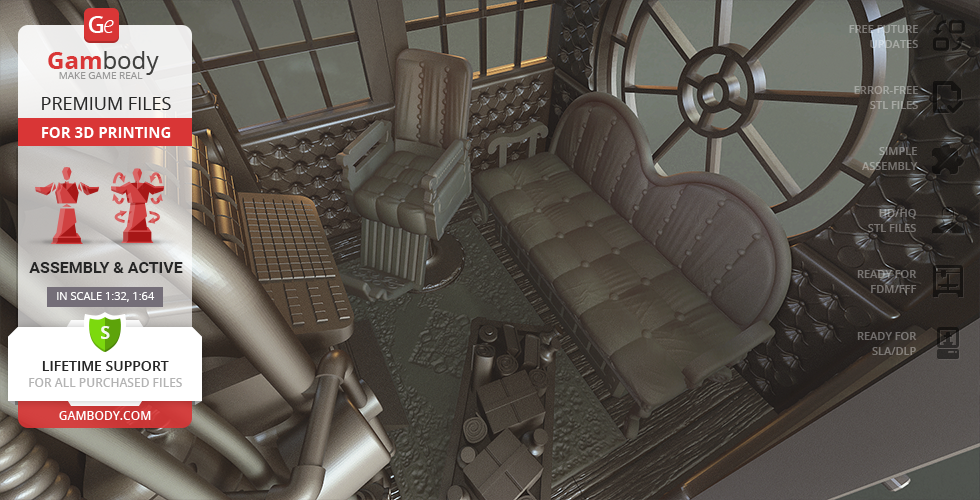
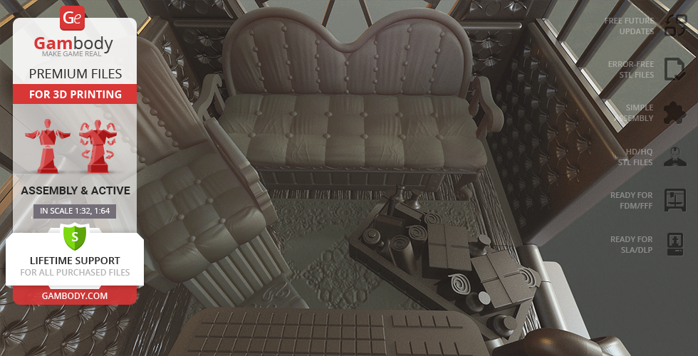
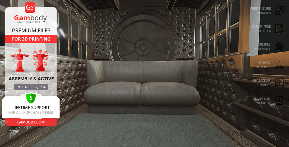
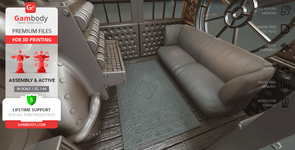
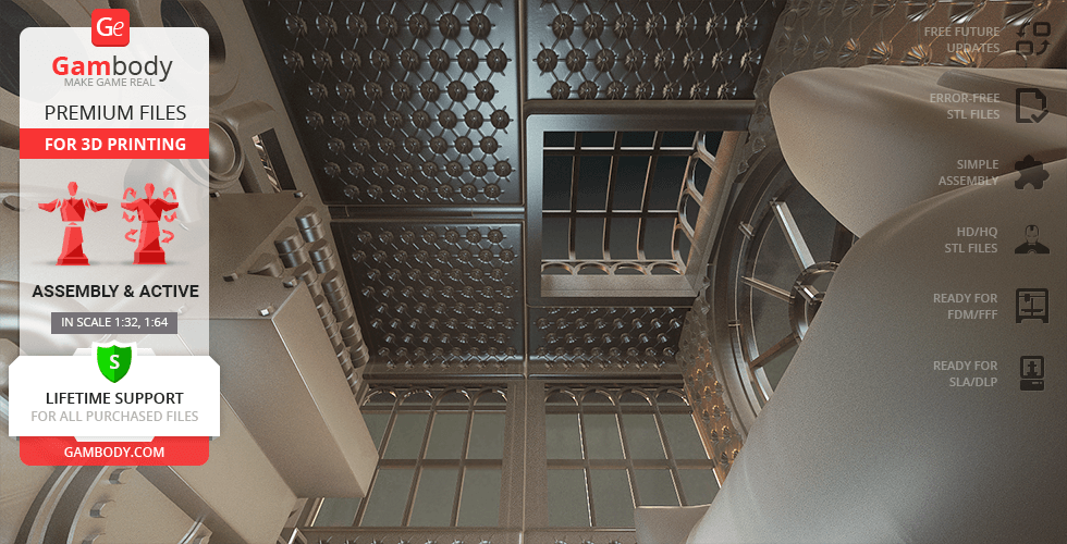
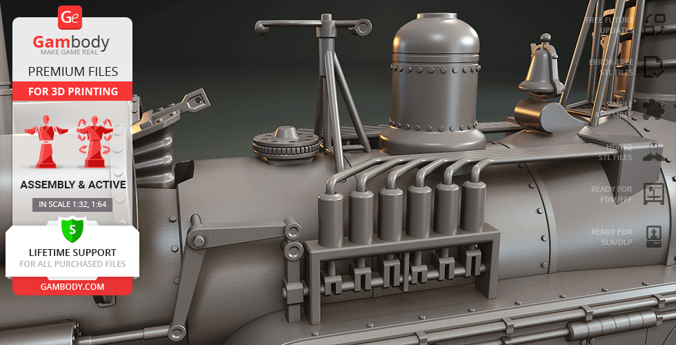
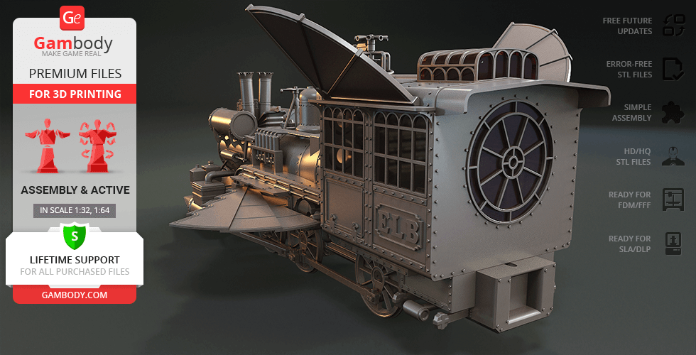
Thus, various special mechanisms were introduced into the model to make sure that the parts comprising the running gear, as well as the details of the frame, body, and the cab’sinterior, are both authentic and highly functional (please, see "Versions' specifications", "Assembly video" and photo preview slider).
The cutting of the model was chosen to ensure the cleanest 3D printing result possible and to minimize the amount of material needed to print the generated support, e.g. locomotive’s cowcatcher, headlamp, bell, drive rods, flux capacitor, chimneys, and many more parts come as separate STL files.
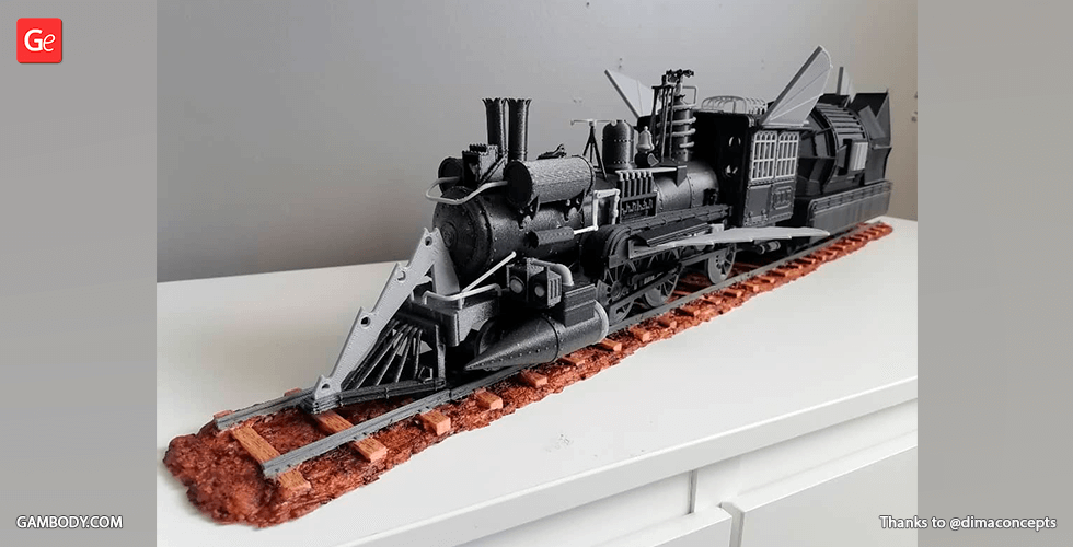
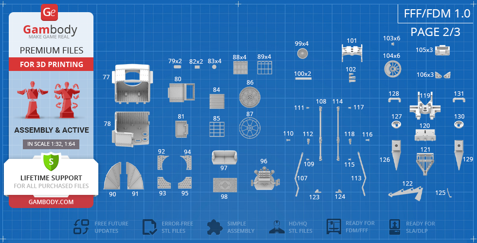
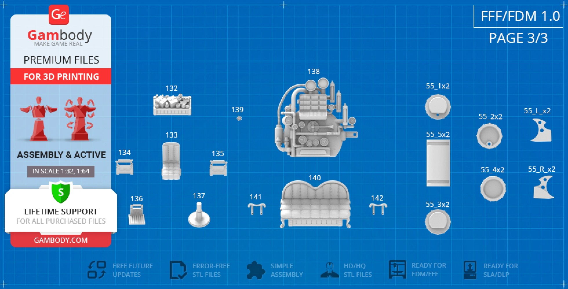
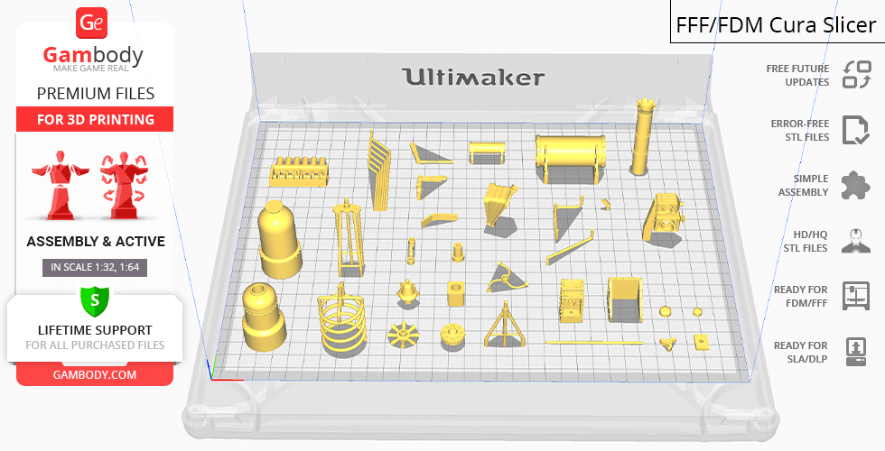
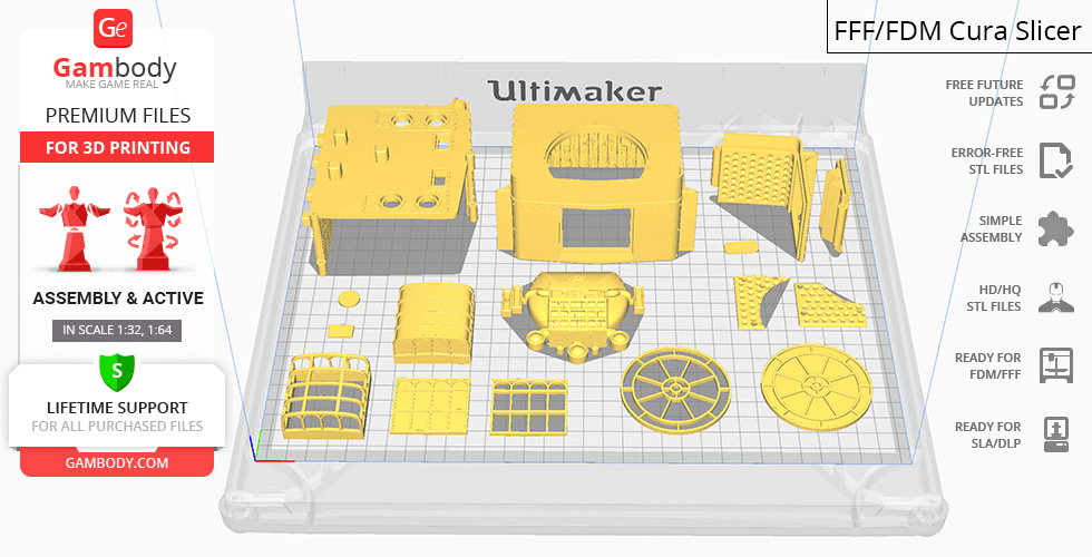
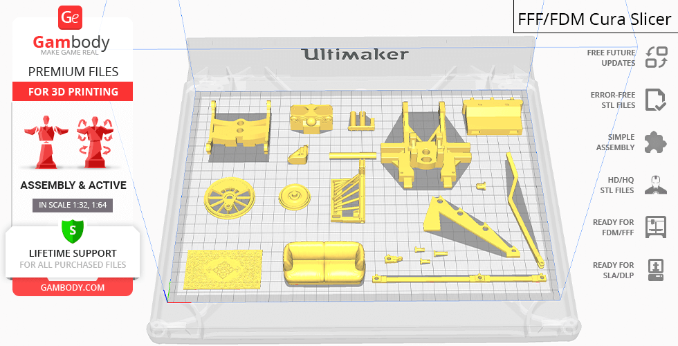
All assembly parts are provided in STL files of FFF/FDM version in recommended positions that were worked out in order to ensure the smoothness of the details’ surfaces after printing and so that the 3D printing beginners won't face difficulties when placing the parts on a build plate. We highly recommend that you get acquainted with the “Assembly video” and "Assembly Manual" before getting down to the Jules Verne Train Locomotive model.
The model is saved in STL files, a format supported by most 3D printers. All STL files for 3D printing have been checked in Netfabb and no errors were shown.The model’s scale was calculated from the length of the Sierra No. 3 locomotive which is 14336 mm. The 3D printing model’s chosen scale is 1:32 for the FFF/FDM version and 1:64 for the DLP/SLA/SLS version.
VERSIONS' SPECIFICATIONS
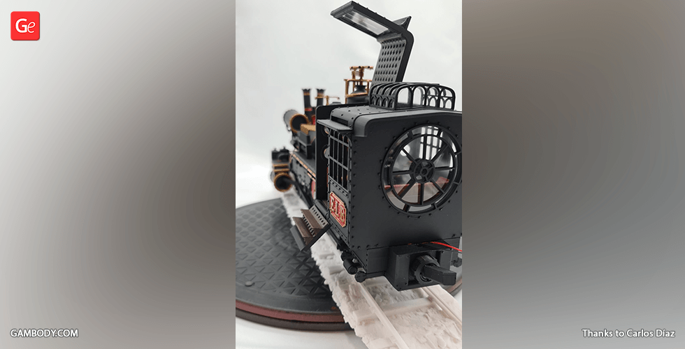
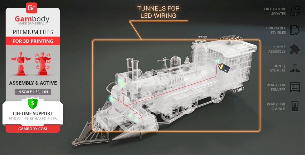
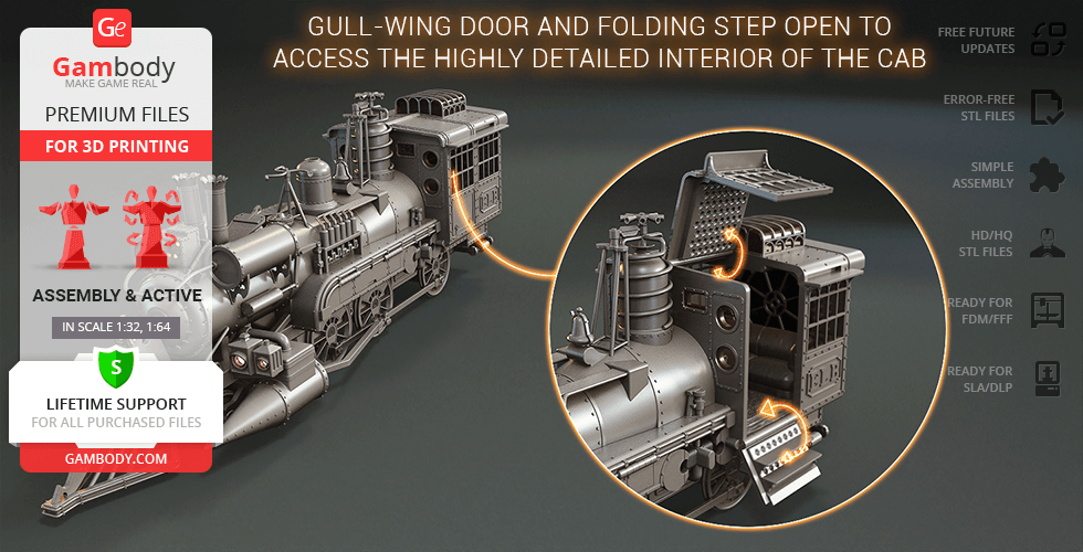
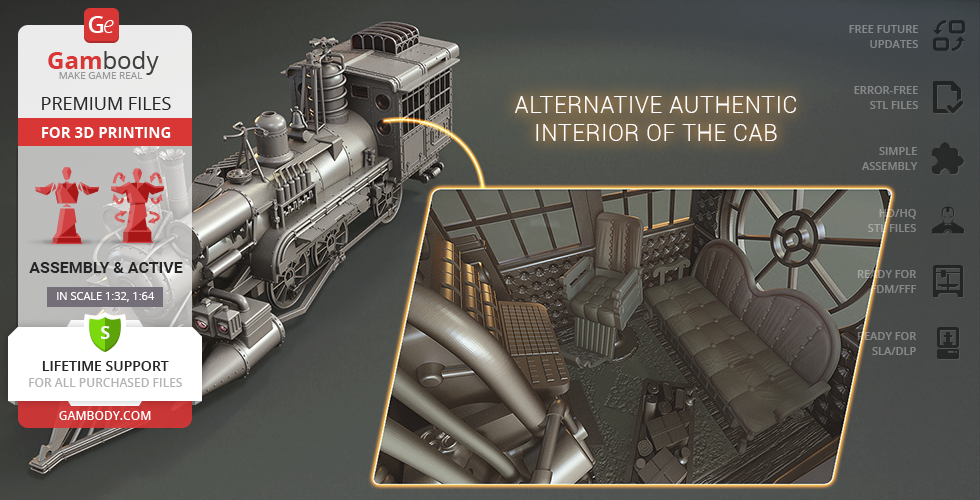
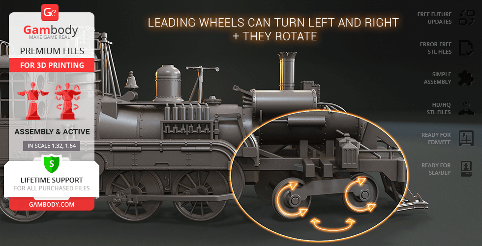
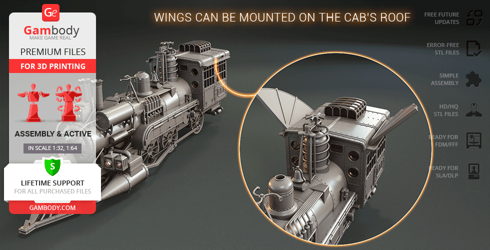
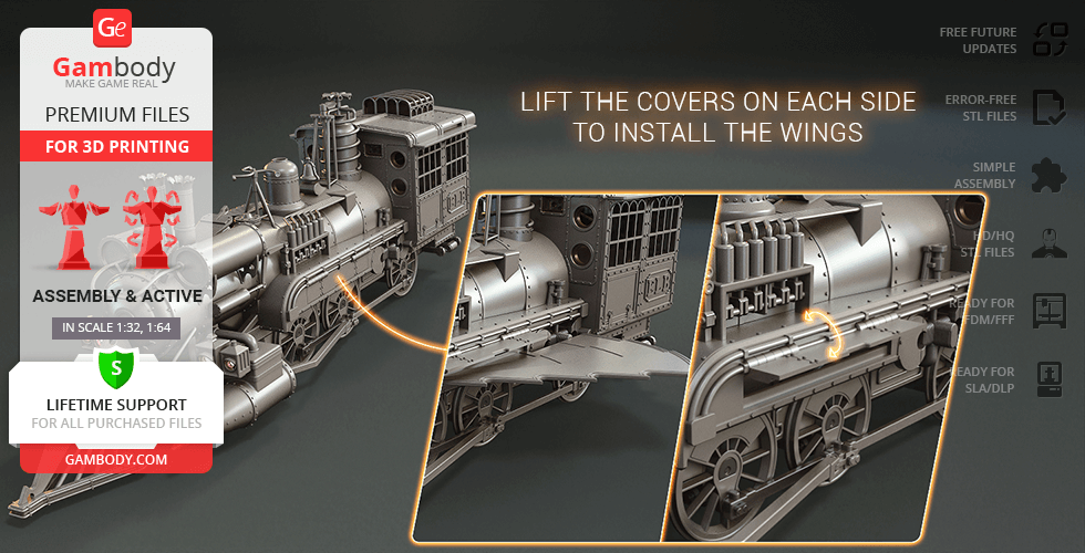
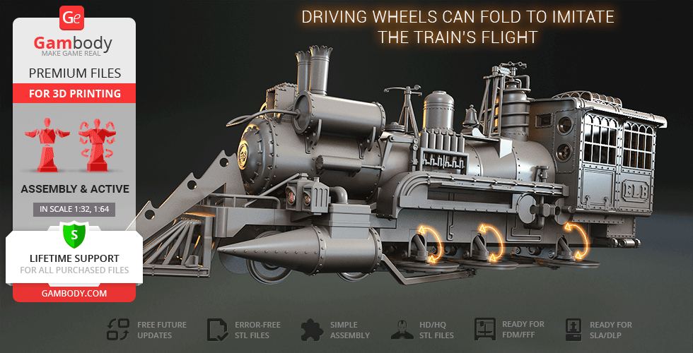
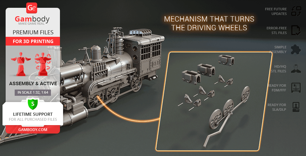
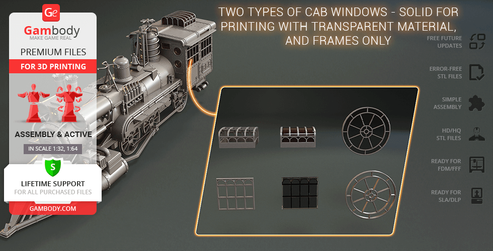
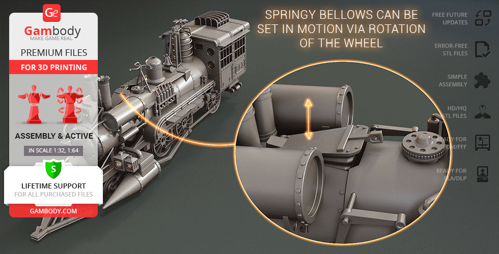
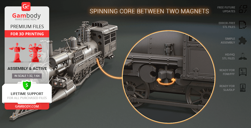
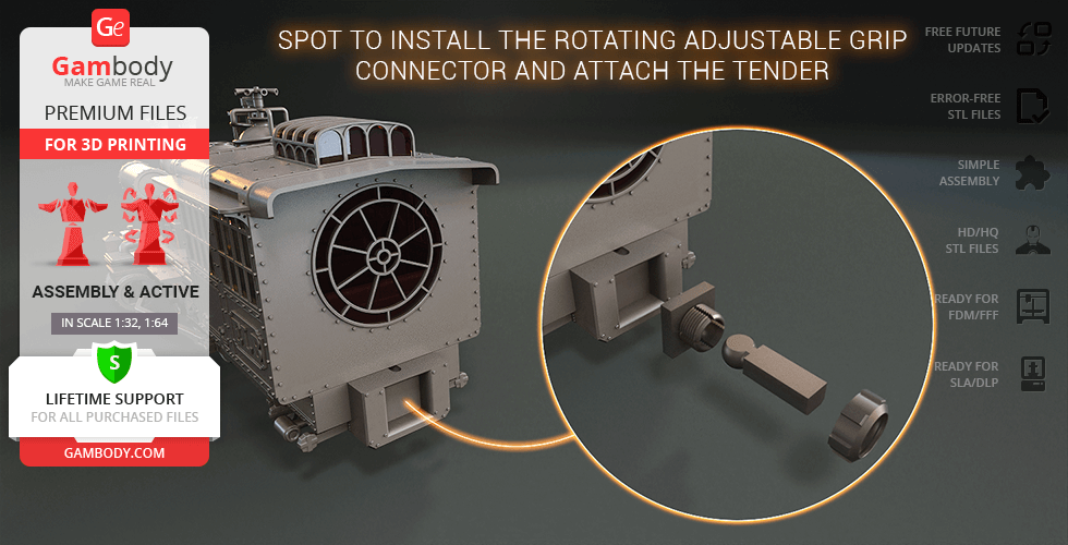
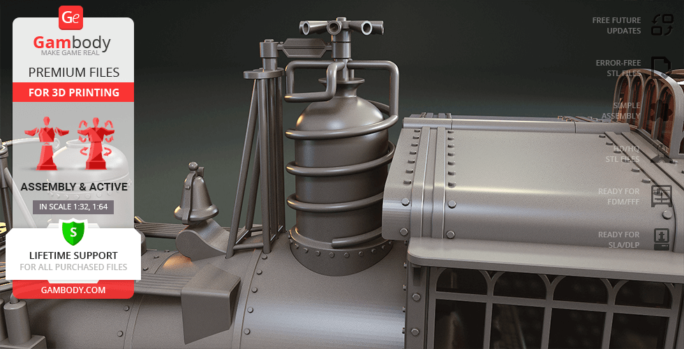
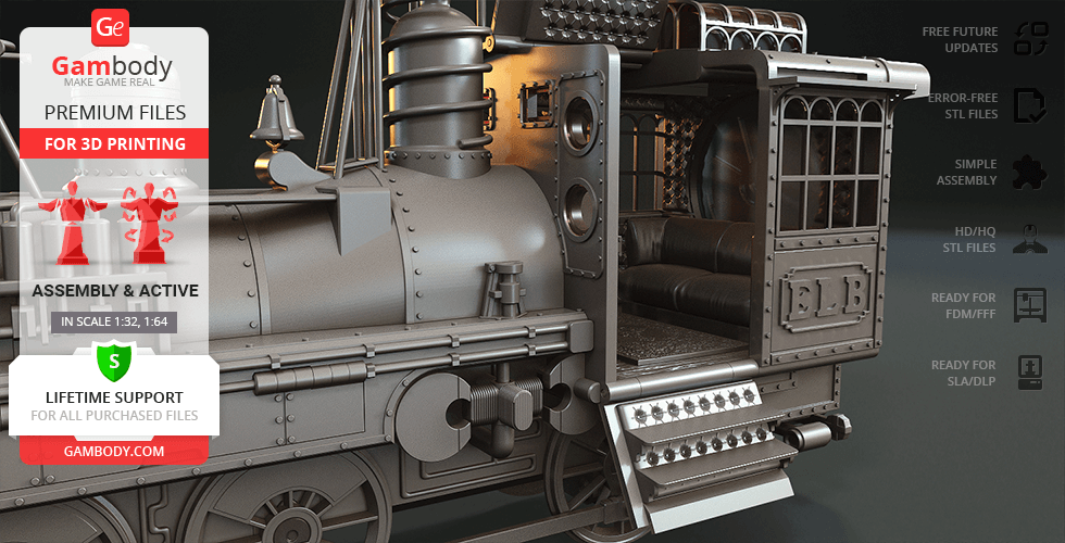
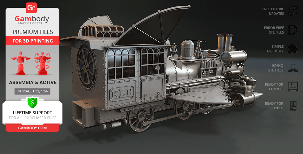
FFF/FDM 1.0 version features:- Contains 142 parts;- A printed model is 168 mm tall, 240 mm wide, 448 mm deep;- Gull-wing door and folding step open to access the interior of the cab that boasts an exceptional level of detail;- There are two interior options for you to choose from;- Synchronised rotation of driving wheels is ensured by an authentic active mechanism of locomotive’s runninggear;- Two front leading axles turn left and right + leading wheels can also rotate;- One pair of "time travel" wings can be mounted on the cab’s roof, another can be installed on each side of the locomotive once you lift the covers;- Driving wheels (all 9 of them) can fold to imitate the train’s flight;- There are two types of cab windows - solid frames with window glasses for printing with transparent filament, and frames only;- The locomotive's boiler features a lot of articulatedelements: rotating coil, propeller, and anemometer;- Also, there are springy bellows that can be fastened to the rotating wheel with a rope and set in motion via rotation of the wheel;- Spinning core is located between two magnets on the side of the locomotive;- There is a spot to install the rotating adjustable grip connector and attach the Jules Verne Train Tender;- You can light up the model's headlamp, boiler lamp, and cab. LED wiring can be easily installed throughout the body of the vehicle, while the battery can be hidden inside the cab or in Jules Verne Train Tender;- The assembly of the version's parts requires additional "pins" made out of short pieces of regular 1.75mm filament;- All parts are divided in such a way that you will print them with the smallest number of support structures.
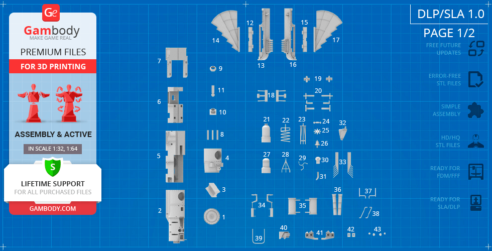
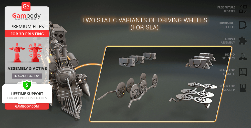
DLP/SLA/SLS 1.0 version features:- Contains 85 parts;- A printed model is 84 mm tall, 120 mm wide, 224 mm deep;- Gull-wing door and folding step open to access the interior of the cab that boasts an exceptional level of detail;- There are two interior options for you to choose from;- Synchronised rotation of driving wheels is ensured by an authentic active mechanism of locomotive’s runninggear;- Two front leading axles turn left and right + leading wheels can also rotate;- This version also features two static variants of driving wheels - usual and folded for flight;- One pair of "time travel" wings can be mounted on the cab’s roof, another can be installed on each side of the locomotive once you lift the covers;- Driving wheels (all 9 of them) can fold to imitate the train’s flight;- There are two types of cab windows - solid frames with window glasses for printing with transparent material, and frames only;- The locomotive's boiler features a lot of articulatedelements: rotating coil, propeller, and anemometer;- Also, there are springy bellows that can be fastened to the wheel with a rope;- Spinning core is located between two magnets on the side of the locomotive;- There is a spot to install the rotating adjustable grip connector and attach the Jules Verne Train Tender;- You can light up the model's headlamp, boiler lamp, and cab. LED wiring can be easily installed throughout the body of the vehicle, while the battery can be hidden inside the cab or in Jules Verne Train Tender;- The assembly of the version's parts requires additional "pins" made out of short pieces of a regular paper clip;- All parts are divided in such a way to fit the build plates and to ensure that support structures are generated where needed.
You can get the model of Jules Verne Train Locomotive for 3D Printing immediately after the purchase! Just click the green Buy button in the top-right corner of the model’s page. You can pay with PayPal or your credit card.
Watch the tutorial on how to assemble Jules Verne Train Locomotive 3D Printing Model at Gambody YouTube channel.
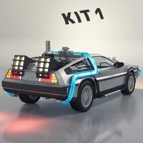
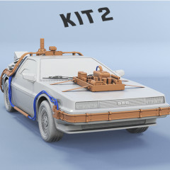
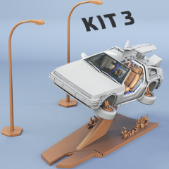
Also, you may like Jules Verne Train Tender3D Printing Model, DeLorean 3D Printing Model, as well as other Back to the Future 3D Printing Models.
_______FAQ: Where can I print a model if I have no printer?How to get started with 3D printing?How to set up my 3D printer?How to choose right 3D model print bed positioning? How to paint printed figurine?
Average customer rating (11 reviews)
4.9
Ratings breakdown
Click a star rating to filter reviews
Overall experience
Level of detail in the model
4.9
Model cut quality and assembly guide
4.9
Clarity and accuracy of the model page
4.9
Level of detail in the model
5
Model cut quality and assembly guide
5
Clarity and accuracy of the model page
5
Level of detail in the model
4
Model cut quality and assembly guide
4
Clarity and accuracy of the model page
4
Level of detail in the model
5
Model cut quality and assembly guide
5
Clarity and accuracy of the model page
5
Level of detail in the model
5
Model cut quality and assembly guide
5
Clarity and accuracy of the model page
5
Level of detail in the model
5
Model cut quality and assembly guide
5
Clarity and accuracy of the model page
5
Level of detail in the model
5
Model cut quality and assembly guide
5
Clarity and accuracy of the model page
5
Level of detail in the model
5
Model cut quality and assembly guide
5
Clarity and accuracy of the model page
5
Level of detail in the model
5
Model cut quality and assembly guide
5
Clarity and accuracy of the model page
5
Level of detail in the model
5
Model cut quality and assembly guide
5
Clarity and accuracy of the model page
5
Level of detail in the model
5
Model cut quality and assembly guide
5
Clarity and accuracy of the model page
5
Level of detail in the model
5
Model cut quality and assembly guide
5
Clarity and accuracy of the model page
5
Below you'll find detailed slicing settings for Bambu Studio 2.0+, Orca Slicer 2.0+, UltiMaker Cura 5.0+, PrusaSlicer 2.0+, Slic3r 1.3+, Simplify3D 5.0+ to help you get the best results when printing this model. These settings are optimized specifically for this 3D model, but please note they may need slight adjustments depending on your printer or filament. When in doubt, refer to your printer's user manual.
To avoid printing issues and achieve the best quality, we highly recommend applying the following settings:
For better quality use 0.12 mm layer height, for fast printing use 0.2 mm layer height. For pins and the Ge connectors, use 0.2 layer height.
120-150% of your Layer Height
But you can paint the seam if you want.
You have to calibrate this parameter
You have to calibrate this parameter
You have to calibrate this parameter
For pins and power elements of the structure, such as the vehicle frame, use 3 loop
Disabled for vehicles and enabled for characters
For 0,2 Layer Height
The parameters in this tab vary greatly, it all depends on the quality of your printer. For example, if you have a classic Ender3, stick to the minimum parameters, but if you have a newer printer, for example Anycubic cobra 3 v2, you can select the maximum recommended values
Settings for advanced users, change these parameters only if you have sufficient 3D printing expertise
Enable this parameter if your model requires supports
We also recommend placing and removing supports manually in some places using special button
1-2 loops for more thick support
Top Z distance = 1-1.3 layer Height. If the supports are hard to remove, try increasing this setting by 0.1-0,4 mm
Bottom Z distance = 1-1.3 layer Height. If the supports are hard to remove, try increasing this setting by 0.1-0,4 mm
You have to calibrate this parameter which one is better for your filament
Increase this parameter if the supports are hard to remove from walls
For PLA and PETG filament types
5-8 mm is optional for small prints that have bad adhesion to the build plate
You have to calibrate this parameter
Read the description on your filament roll
Read the description on your filament roll and increase this parameter for fast printers
Read the description on your filament roll and increase this parameter for fast printers
For better quality use 0.12 mm layer height, for fast printing use 0.2 mm layer height. For pins and the Ge connectors, use 0.2 layer height.
120-150% of your Layer Height
But you can paint the seam if you want.
0.01-0.05 You have to calibrate this parameter
0.01-0.05 You have to calibrate this parameter
0.1-0.2 You have to calibrate this parameter
For pins and power elements of the structure, such as the vehicle frame, use 3 loop
Disabled for vehicles and ships, enabled for characters
For 0,2 Layer Height
For 0,2 Layer Height
The parameters in this tab vary greatly, it all depends on the quality of your printer. For example, if you have a classic Ender3, stick to the minimum parameters, but if you have a newer printer, for example, Anycubic Kobra 3 Or Bambulab A1, you can select the maximum recommended values.
Settings for advanced users, change these parameters only if you have sufficient 3D printing expertise
Enable this parameter if your model requires supports
We also recommend placing and removing supports manually in some places using special button
Top Z distance = 1-1.3 layer Height. If the supports are hard to remove, try increasing this setting by 0.1-0,4 mm
Bottom Z distance = 1-1.3 layer Height. If the supports are hard to remove, try increasing this setting by 0.1-0,4 mm
Increase this parameter if the supports are hard to remove from walls
For PLA and PETG filament types
5-8 mm is optional for small prints that have bad adhesion to the build plate
Read the description on your filament roll
Read the description on your filament roll and increase this parameter for fast printers
You have to calibrate this parameter
Read the description on your filament roll and increase this parameter for fast printers
Read the description on your filament roll
This field is filled in according to your printer specifications when you add it to the slicer.
You can add custom G-code here for the start and end of the print. However, be careful - this is for advanced users only!
You have to calibrate your printer using Ge retraction test models
Retraction Length: For direct-drive setups use 0.5 mm to 2.5 mm; for Bowden extruders use 5 to 7 mm
This is how fast the filament is pulled back—40-60 mm/s for direct drive and 30-50 mm/s for Bowden setups.
You have to calibrate this parameter: Reduce it until the printer starts to hit the parts with the nozzle during printing, then increase it by 0.2.
For better quality use 0.12 mm layer height, for fast printing use 0.2 mm layer height. For pins and the Ge connectors, use 0.2 layer height.
120-150% of your Layer Height
To increase the strength of the print parts, use wall line count: 3
For pins and connectors use 50% Infill
These parameters are for standard PLA plastic. If you are using a different type of plastic, check the printing temperature recommended by the manufacturer. Also, read the description on your filament spool. For fast printers, add +30 °C to the current parameters.
The parameters in this tab vary greatly, it all depends on the quality of your printer. For example, if you have a classic Ender3, stick to the minimum parameters, but if you have a newer printer, for example Anycubic cobra 3 v3, you can select the maximum recommended values
Settings for advanced users, change these parameters only if you have sufficient 3D printing expertise.
You need to calibrate this parameter using Gambody test models. These values are average values for a Direct Drive extruder; for a Bowden extruder, the values should be increased.
You need to calibrate this parameter using Gambody test models. These values are average values for a Direct Drive extruder; for a Bowden extruder, the values should be increased.
Use this value other than 0 if your nozzle catches on the internal infill during travel moves. Try to keep this value as low as possible in height.
Use normal supports to support large, straight surfaces (most mechanical or technical parts).
You have to calibrate this parameter according to the capabilities of your printer and your filament, using a Gambody test models.
Use 1 instead of 0 if your supports are thin and tall. They will be harder to remove, but much stronger.
Top Z distance = 1-1.3 layer Height. If the supports are hard to remove, try increasing this setting by 0.1-0,4 mm
Increase this parameter if the supports are hard to remove from walls
Use tree supports to support complex objects, such as characters.
You have to calibrate this parameter according to the capabilities of your printer and your filament, using a Gambody test models.
Top Z distance = 1-1.3 layer Height. If the supports are hard to remove, try increasing this setting by 0.1-0,4 mm
Increase this parameter if the supports are hard to remove from walls
Use a skirt for all parts when printing on outdated printers.
Use a brim when printing thin but tall parts, as well as parts with a small bed adhesion area.
For better quality use 0.12 mm layer height, for fast printing use 0.2 mm layer height. For pins and the Ge connectors, use 0.2 layer height.
120-150% of your Layer Height
for 0.2 Layer Height
But you can paint the seam if you want.
(for PLA and PETG)
(5-8 mm is optional for small prints that have bad adhesion to the build plate)
Enable this parameter if your model requires supports
(45-50 degree)You have to calibrate this parameter according to the capabilities of your printer
and your filament, using a Gambody test models.
Top contact Z distance = 1-1.3 layer Height. If the supports are hard to remove, try
increasing this setting by 0.1-0,4 mm
Top contact Z distance = 1-1.3 layer Height. If the supports are hard to remove, try
increasing this setting by 0.1-0,4 mm
Increase this parameter if the supports are hard to remove from walls
The parameters in this tab vary greatly, it all depends on the quality of your printer. For example, if you have a classic Ender3, stick to the minimum parameters, but if you have a newer printer, for example Anycubic cobra 3 v3, you can select the maximum recommended values
Settings for advanced users, change these parameters only if you have sufficient 3D printing expertise. Use the minimum value for outdated printers without acceleration calibration, and the maximum value for modern printers if you need it.
These settings only work for 3D printers with multiple extruders
You can try setting all parameters in this section, except the First layer, to values between 0.75% of your nozzle diameter and 1.25% of your nozzle diameter. Adjusting them will help you work out the optimal parameters for the best quality for your print. As for the First layer, you can set it to 150% of the diameter of your nozzle for better adhesion to the build plate (for a nozzle with a diameter of 0.4 mm, the First layer extrusion width can be from 0.3 mm to 0.5 mm)
For better printing quality you have to calibrate this parameter using Gambody test model.
Check your filament manufacturer's temperature recommendations on the spool.
Cooling parameters depends on the material you use for printing.
*for PLA
For better quality use 0.12 mm layer height, for fast printing use 0.2 mm layer height. For pins and the Ge connectors, use 0.2 layer height.
120-150% of your Layer Height
For 0.12 Layer Height
For 0.12 Layer Height
For pins and connectors use 50% Infill
Use skirt for outdated 3d printers
(5-8 mm is optional for small prints that have bad adhesion to the build plate)
Enable this parameter if your model requires supports
(45-60 degree)You have to calibrate this parameter according to the capabilities of your printer and your filament, using a Gambody test models
Contact Z distance = 1-1.3 layer Height. If the supports are hard to remove, try increasing this setting by 0.1-0,4 mm
The parameters in this tab vary greatly, it all depends on the quality of your printer. For example, if you have a classic Ender3, stick to the minimum parameters, but if you have a newer printer, for example Anycubic cobra 3 v3, you can select the maximum recommended values
Settings for advanced users, change these parameters only if you have sufficient 3D printing expertise. Use the minimum value for outdated printers without acceleration calibration, and the maximum value for modern printers if you need it.
You have to calibrate this parameter from 0.9 to 1.1 according to the capabilities of your printer and your filament, using a Gambody test models.
Check your filament manufacturer's temperature recommendations on the spool.
Cooling parameters depends on the material you use for printing.
Calibrate this value if you need to reduce or improve the adhesion between the plastic and the heat bed
Your current nozzle diameter
You need to calibrate this parameter using Gambody test models. These values are average values for a Direct Drive extruder; for a Bowden extruder, the values should be increased.
Your current nozzle diameter
You have to calibrate this parameter using Gambody test models.
You need to calibrate this parameter using Gambody test models. These values are average values for a Direct Drive extruder; for a Bowden extruder, the values should be increased.
For better quality use 0.12 mm layer height, for fast printing use 0.2 mm layer height. For pins and the Ge connectors, use 0.2 layer height.
For 0,2 Layer Height
For 0,2 Layer Height
To increase the strength of the print parts, use Outline Perimeters: 3
You can enable this parameter to print rounded or spherical models, as well as character models.
Use this option only if your parts are too tight. but better calibrate your printer extrusion
Use this option only if your parts are too tight. but better calibrate your printer extrusion
Use 2 and more if you want to create skirt instead brim
1-2 for skirt and 10-20 for brim
Use for wipe nozzle if you need
Use For ABS filament
For pins and connectors use 50% Infill
Top Z distance = 1-1.3 layer Height. If the supports are hard to remove, try increasing this setting by 0.1-0,4 mm
Calibrate your filament and detect optimal temperature for it
Average temperature for PLA filament
The parameters in this tab vary greatly, it all depends on the quality of your printer. For example, if you have a classic Ender3, stick to the minimum parameters, but if you have a newer printer, for example Anycubic cobra 3 v3, you can select the maximum recommended values
Settings for advanced users, change these parameters only if you have sufficient 3D printing expertise.