


Files
3D model format
Stereolithography (.stl)
Total files
Slicer settings
Mesh error check
Netfabb
Support
Lifetime support from Gambody team
Update requests
Available to verified buyers
Model complexity
Expert: demanding print setup with intricate parts. Requires post-processing skills, attention to detail, and patience.
Model versions
FFF/FDM
Assembly method
not specified
Features
DLP/SLA
Assembly method
not specified
Features
Additional details
Part of diorama
No
Special pack included
No
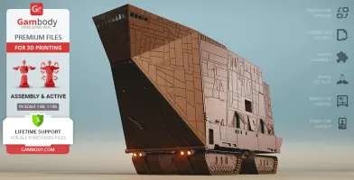
You will get instant access to the STL files of Sandcrawler 3D Printing Model | Assembly + Active after completing your purchase. Simply add the model to your cart and check out using PayPal, credit or debit card, Apple Pay, Google Pay, Alipay, or other available payment methods.
Watch the assembly video for Sandcrawler 3D Printing Model | Assembly + Active, and explore more tutorials, behind-the-scenes content, 3D printing timelapses, and painting guides on the official Gambody YouTube channel.
This 3D model of Sandcrawler inspired by the Star Wars universe consists of files in StereoLithography (.Stl) format that is optimized for 3D printing.
Before printing the files, we strongly recommend reading the PRINTING DETAILS section.
WHAT WILL YOU GET AFTER PURCHASE?
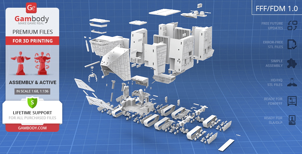
- 2 versions of the Digger Crawler STL files for FFF/FDM, DLP/SLA 3D printers - files for each version are available for download after the purchase
- STL files of high-poly Sandcrawler 3D Model for 3D printing that consist of 149parts
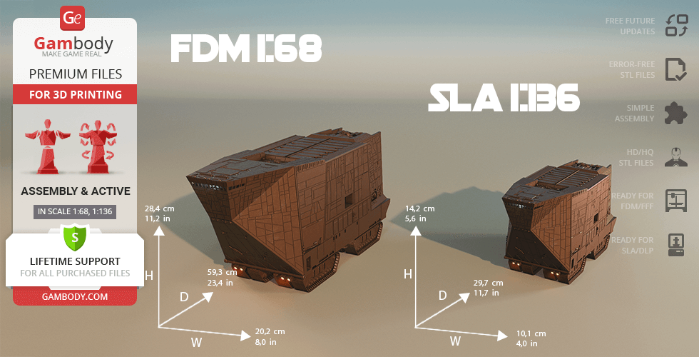
- Sizes:
FFF/FDM: 284 mm tall, 202 mm wide, 593 mm deep
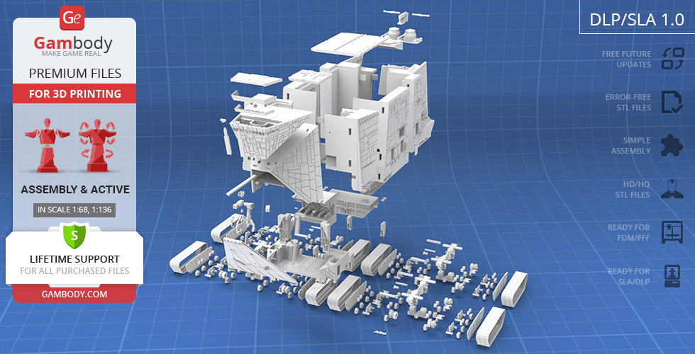
DLP/SLA: 142 mm tall, 101 mm wide, 297 mm deep
- Assembly Manual for FFF/FDM and DLP/SLA versions in PDF format
- Detailed settings that we provide as a recommendation for Cura, Simplify3D and Slic3r for the best print
- Full technical support from the Gambody Support Team
Detailed information about this 3D printing figurine is available in the DESCRIPTION section.
Before printing, take a look at Printing Details for recommended settings and tips to achieve better results.
ABOUT THIS 3D MODEL
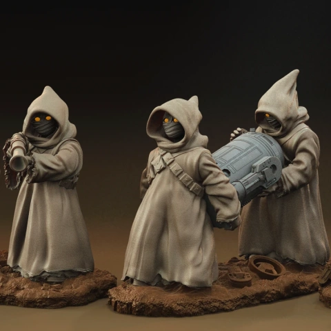
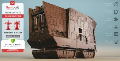
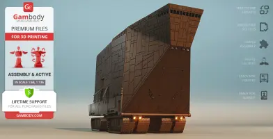
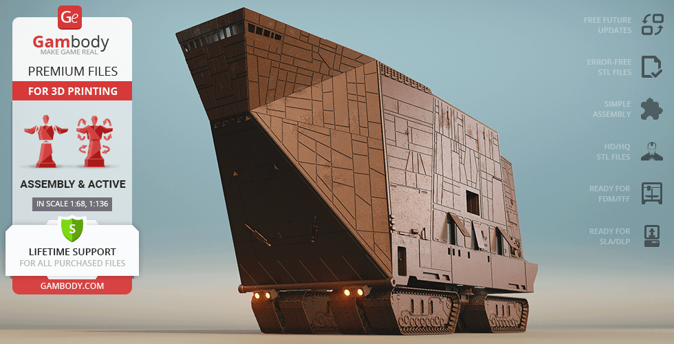
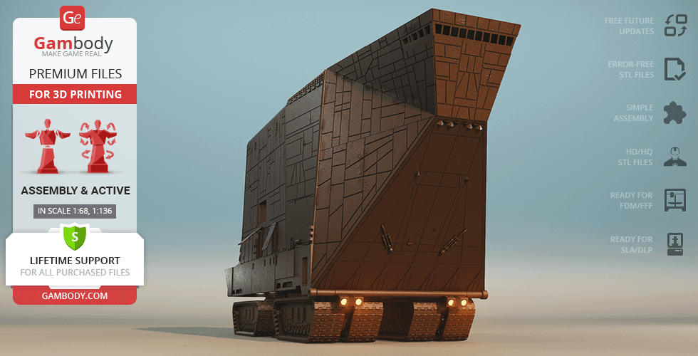
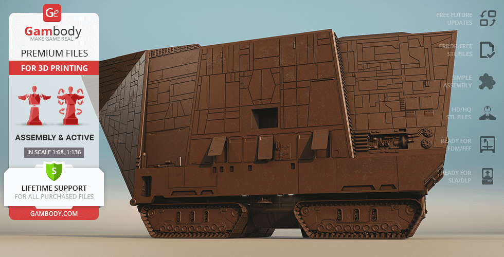
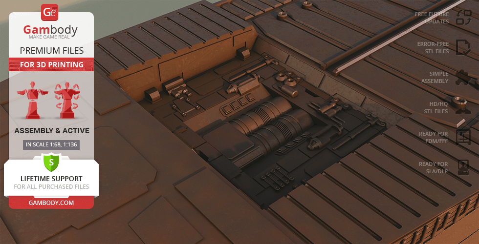
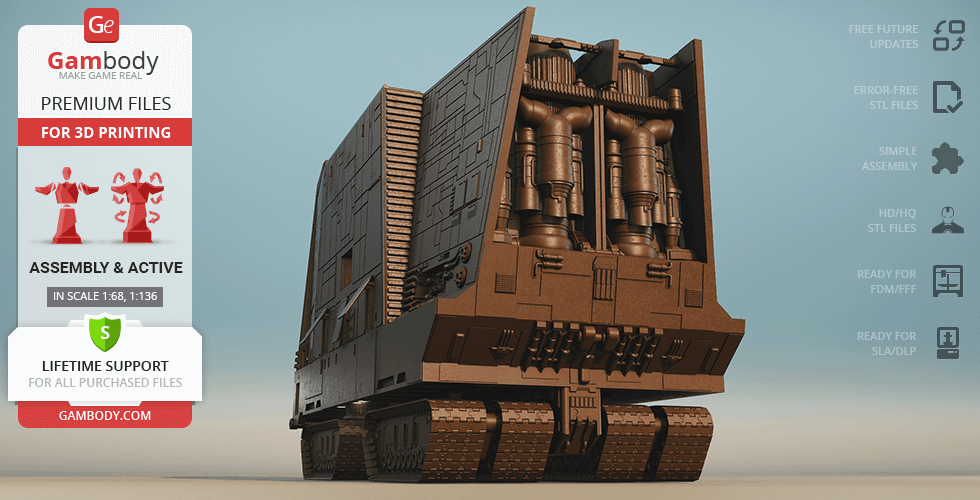
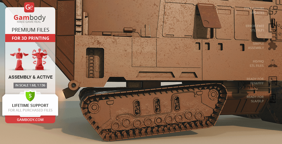
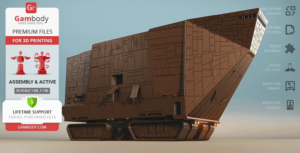
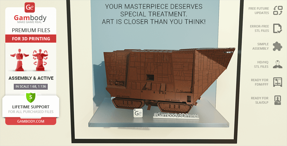
Bulky, old, rusty Sandcrawler from the Star Wars franchise surprises the majority of fans with its unusual, cosmic geometry and 6-storey building height. The fictional tank-like vehicle was used by Jawas, the furry humanoids from the desert planet Tatooine, as their transport and home. These mobile fortresses can survive the most extreme environments and have a special magnetic tube for sucking droids and scraping into the special chambers.
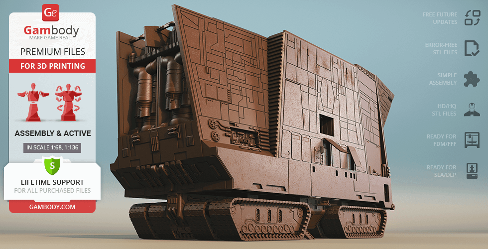
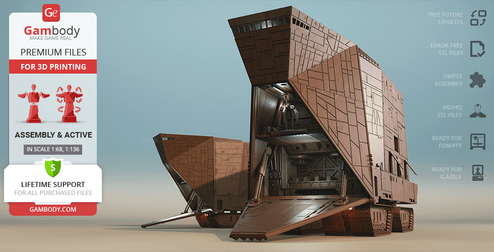
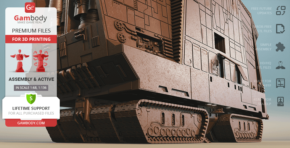
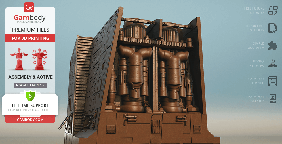
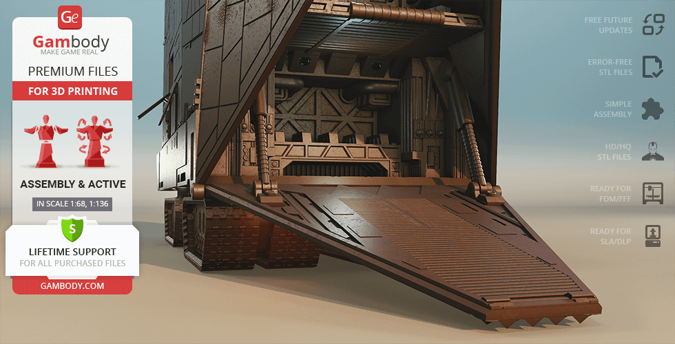
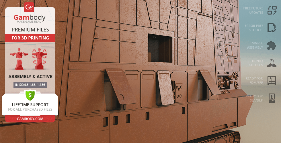
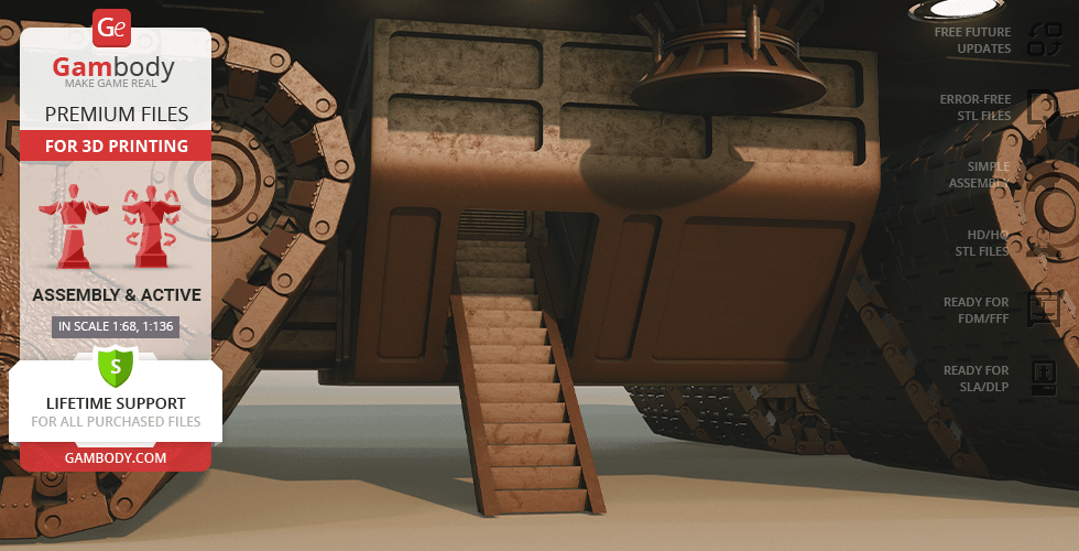
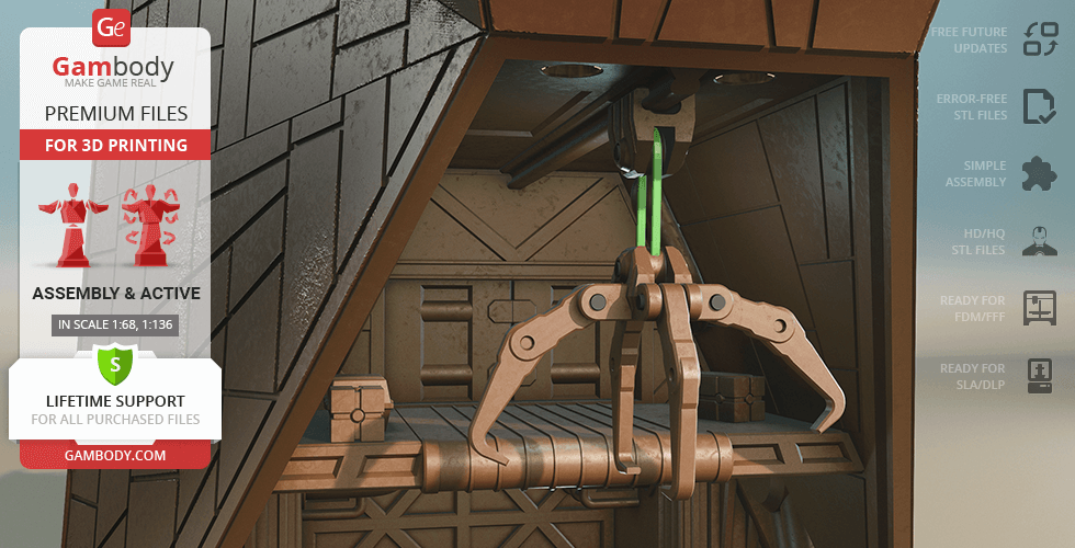
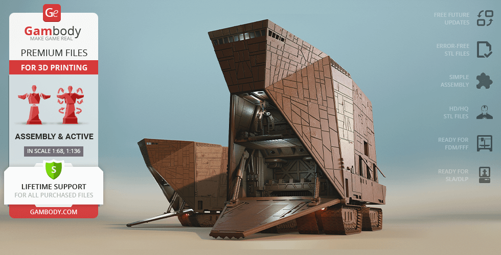
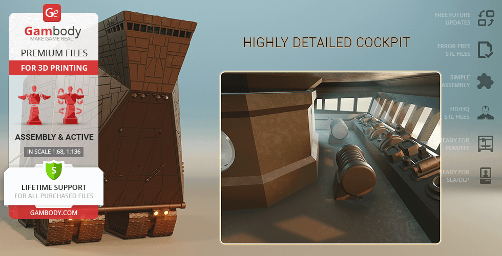
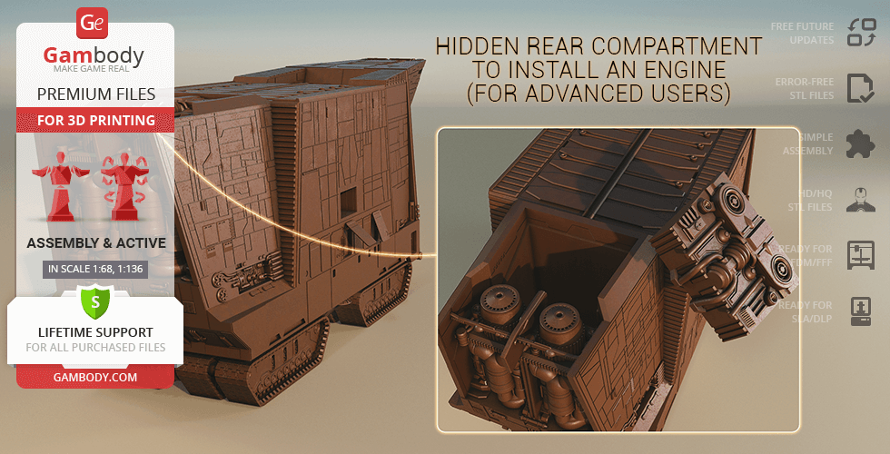
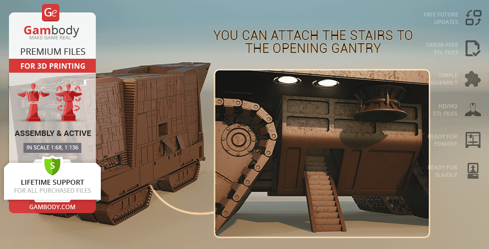
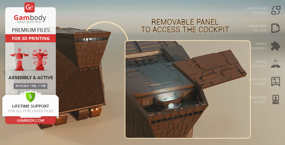
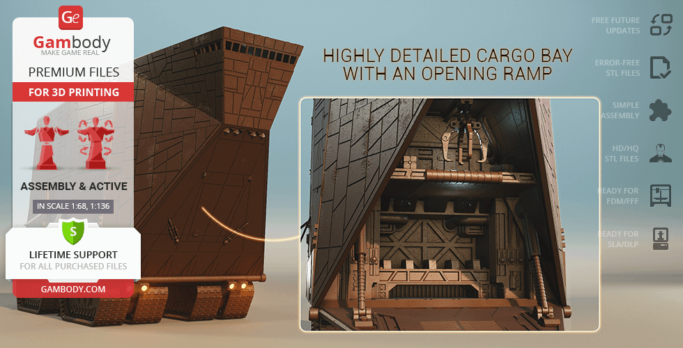
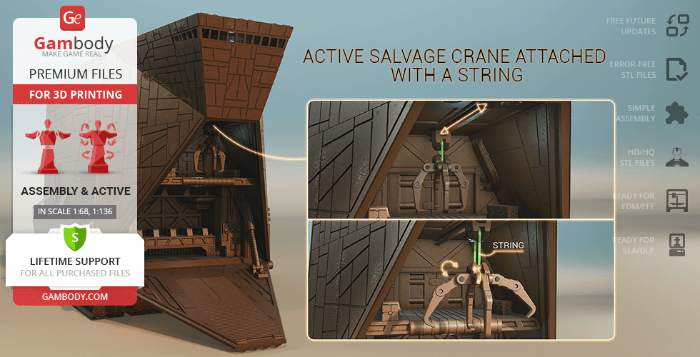
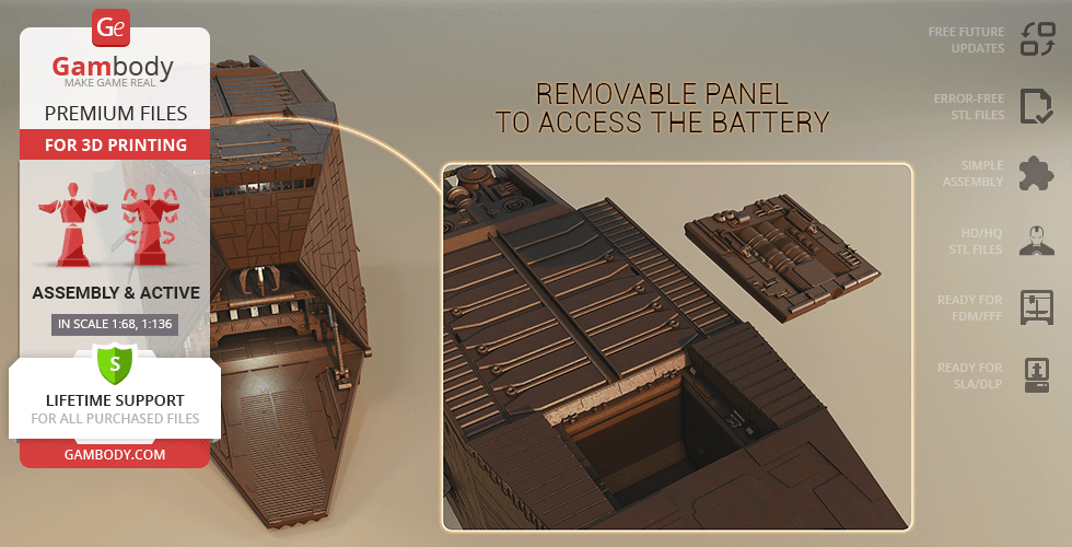
The Sandcrawler 3D printing model, designed by our contributing 3D artist, will undoubtedly blow your mind! Apart from the 3D artist’s accurate and remarkably authentic design, you can enjoy the numerous active mechanisms introduced by Gambody Team. The vehicle has several characteristics that make us feel so excited about it. Highly authentic active suspension with movable wheels will guarantee the mobility of the transport. To access the cockpit you have a removable panel. The large ramp can be opened by pulling the levers in the cockpit. Behind the ramp, there is an active salvage crane, attached with a string that allows height regulation of the system. Advanced users have the option to install the engine in the hidden rear compartment. You can even attach the stairs to the opening gantry! A piece of art that you can purchase and start printing right now!
ADAPTATION FOR 3D PRINTING
Sandcrawler for 3D printing is an active assembly model and its moderation and adaptation for different types of 3D printers took the Gambody team 50 hours in total. Various active mechanisms were introduced, and an authentic active suspension for all treads was worked out.
For you to receive the cleanest 3D printing result possible and minimize the amount of filament needed for generated support, the Sandcrawler was divided into convenient assembly parts.
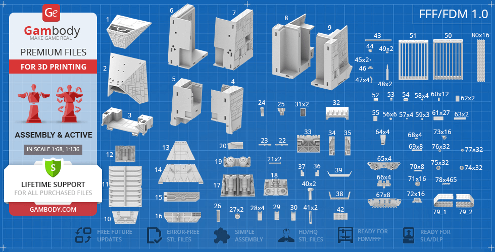
All assembly parts in the FFF/FDM 1.0 version are provided in STL files in recommended positions that were worked out in order to ensure the smoothness of the details’ surfaces after printing and that the 3D printing beginners won't face difficulties when placing the parts on a build plate. After downloading any model's file you will also receive "Assembly Manual" for FFF/FDM 1.0 and DLP/SLA 1.0 versions in PDF format. We highly recommend that you get acquainted with the “Assembly video” and "Assembly Manual" before getting down to the Sandcrawler model.
The model is saved in STL files, a format supported by most 3D printers. All STL files for 3D printing have been checked in Netfabb and no errors were shown.
The model’s scale was calculated from the length of the Sandcrawler - 40 000 mm. The 3D printing model’s chosen scales are 1/68 for the FFF/FDM version and 1/136 for the DLP/SLA version.
VERSIONS' SPECIFICATIONS
FFF/FDM 1.0 version features:
- Contains 80 parts;
- The printed model is 284 mm tall, 202 mm wide, 593 mm deep;
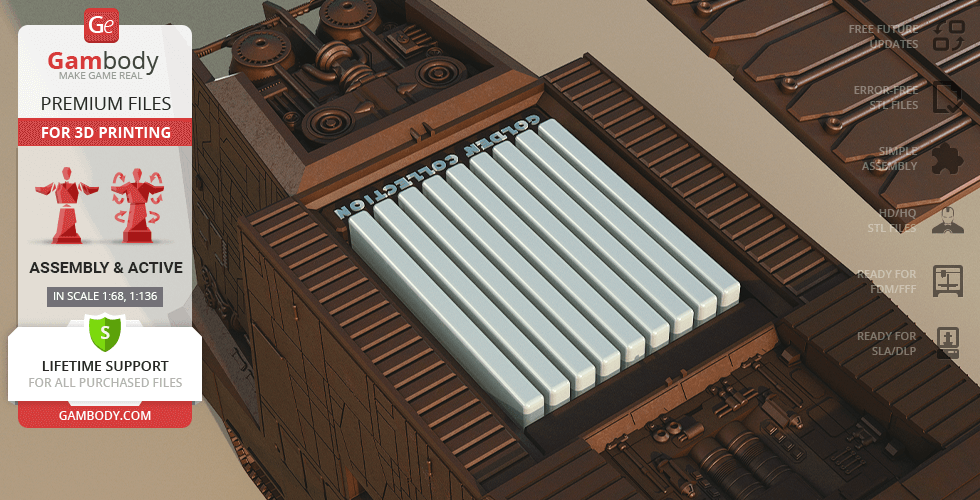
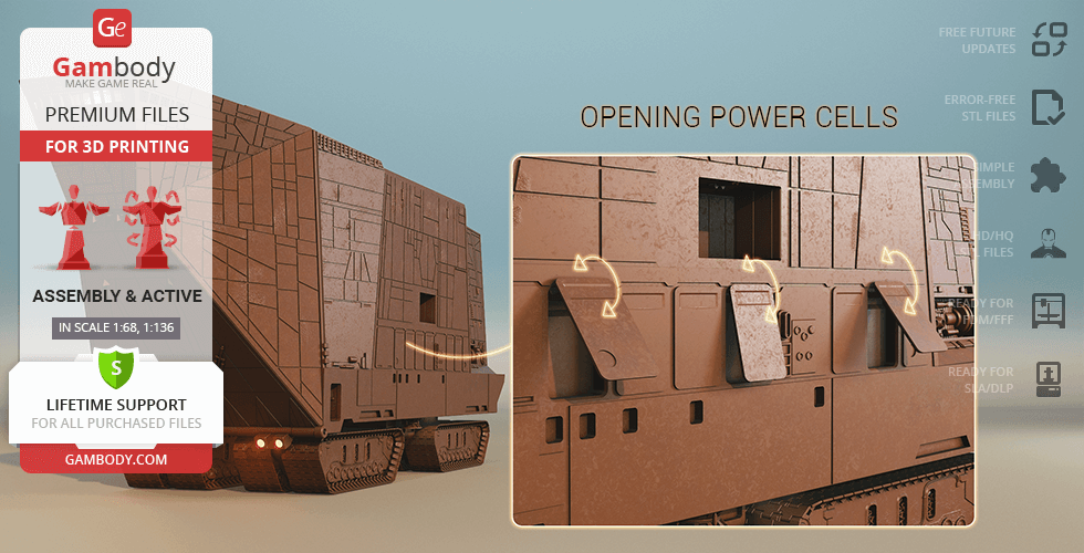
- Opening power cells;
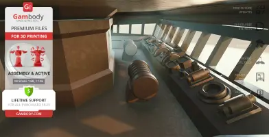
- Highly detailed cockpitinterior;
- Removable panel to accessthe cockpit;
- You can attach the stairs to the openinggantry;
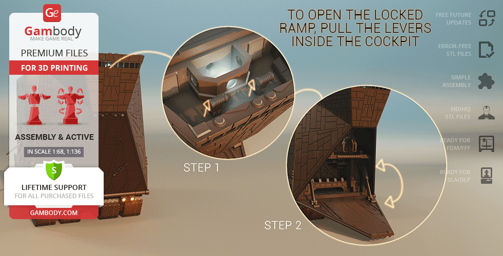
- Opening ramp with hydraulicextenders;
- The ramp can be closed shut using twolocks;
- To open the locked ramp, pull the levers inside the cockpit;
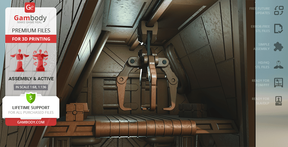
- Highly detailed cargobay;
- Active salvagecrane attached with a string;
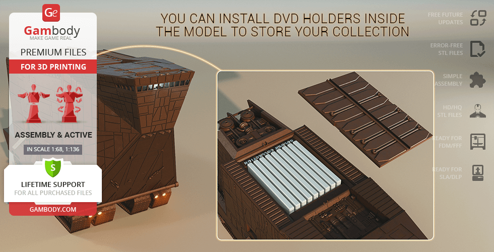
- You can install DVD holders inside the model to store your collection;
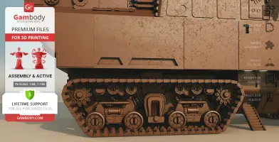
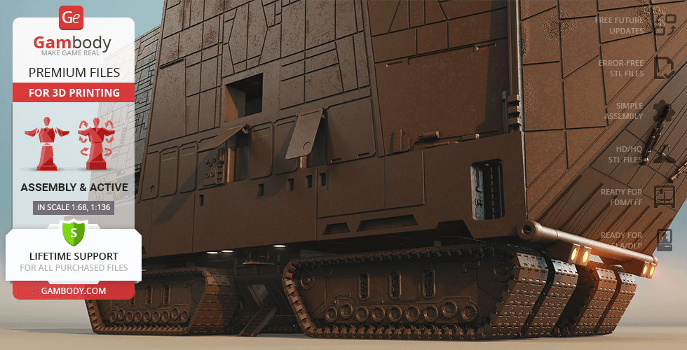
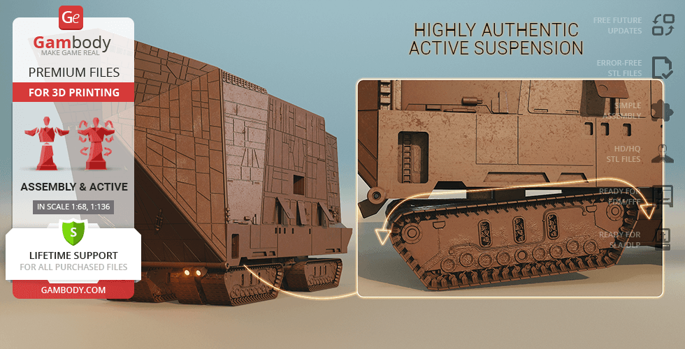
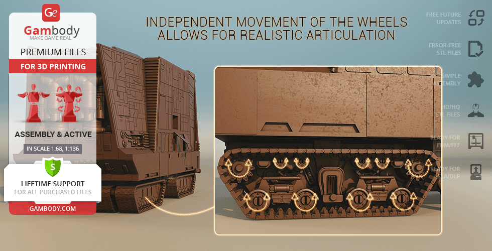
- Highly authentic activesuspension;
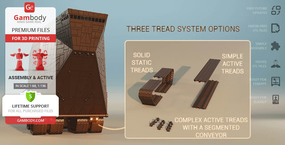
- Three tread system options: solidstatic treads, simpleactive treads with a two-piece conveyor, complextreads with a segmented conveyor for more experienced hobbyists;
- Hidden rear compartment to install an engine (for advanced users);
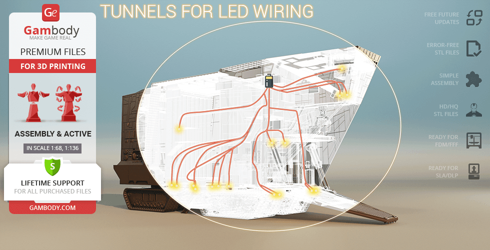
- You can light up the headlights, cockpit, cargobay, underlights, centralcompartment, etc.; the battery can be stored in the hiddencompartment behind the cockpit;
- All parts are divided in such a way that you will print them with the smallest number of support structures.
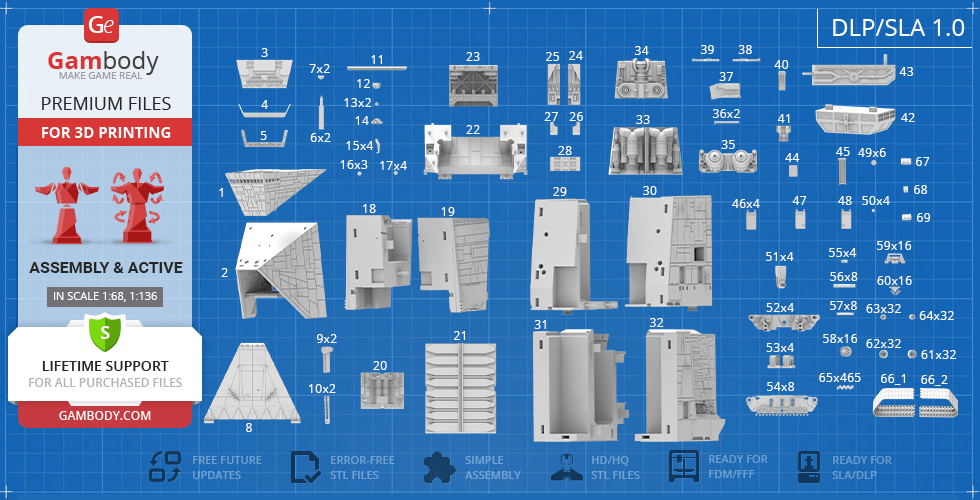
DLP/SLA 1.0 version features:
- Contains 69 parts;
- The printed model is 142 mm tall, 101 mm wide, 297 mm deep;
- Simplifiedcutting for the optimal 3D printing process and easy assembly;
- Opening power cells;
- Highly detailed cockpitinterior;
- Removable panel to accessthe cockpit;
- You can attach the stairs to the openinggantry;
- Opening ramp with hydraulicextenders;
- The ramp can be closed shut using twolocks;
- To open the locked ramp, pull the levers inside the cockpit;
- Highly detailed cargobay;
- Active salvagecrane attached with a string;
- You can install DVD holders inside the model to store your collection;
- Highly authentic activesuspension;
- Twotread system options: solidstatic treads and complextreads with a segmented conveyor for more experienced hobbyists;
- Hidden rear compartment to install an engine (for advanced users);
- You can light up the headlights, cockpit, cargobay, underlights, centralcompartment, etc.; the battery can be stored in the hiddencompartment behind the cockpit;
- All parts are divided in such a way to fit the build plates and to ensure that support structures are generated where needed.
You can get the model of Sandcrawler for 3D Printing immediately after the purchase! Just click the green Buy button in the top-right corner of the model’s page. You can pay with PayPal or your credit card.
Watch the tutorial on how to assemble Sandcrawler 3D Printing Model on Gambody YouTube channel.
Also, you may like other Star Warsmodels for 3D Printing.
_______
FAQ:
Where can I print a model if I have no printer?
How to get started with 3D printing?
How to set up my 3D printer?
How to choose right 3D model print bed positioning?
How to paint printed figurine?
Average customer rating (10 reviews)
4.6
Ratings breakdown
Click a star rating to filter reviews
Overall experience
Level of detail in the model
4.6
Model cut quality and assembly guide
4.1
Clarity and accuracy of the model page
4.5
Level of detail in the model
5
Model cut quality and assembly guide
4
Clarity and accuracy of the model page
5
We have checked the Assembly Manual for the Sandcrawler 3D Model and updated the FFF/FDM version to improve the readability of the part numbers.
The updated PDF has already been uploaded to the model page. To download it, please go to the Source Files tab and re-download any STL file for the FFF/FDM printer type. The revised assembly guide will be included in the downloaded archive.
We have also checked the DLP/SLA instructions and did not find the same issue there.
Thank you again for letting us know. Your feedback helps us improve the files for other makers as well.
Level of detail in the model
3.9
Model cut quality and assembly guide
4
Clarity and accuracy of the model page
3.9
Thank you for your patience while our Moderation Team has been looking into this issue.
After checking, they found that printing the part vertically resolves the hinge issue.
We've replaced the _14_rampPart_b_FDM file with a new one that has the correct print orientation. We recommend redownloading the file from the Source Files and printing it in the new orientation. It's important to print the part with supports enabled, as shown in the attached picture.
This should produce a much stronger print, and the issue with the door hinges should be resolved.
We look forward to your feedback after you've had a chance to try the updated file. We hope this resolves the issue, but if you experience any further difficulties, please don't hesitate to let us know.
We've forwarded your report to our Moderation Team for review. They will carefully examine the model and investigate the issue to determine what adjustments may be required to strengthen the affected parts and resolve the problem.
We'll get back to you as soon as we have an update. Please be assured that we'll do everything possible to help you complete your Sandcrawler project successfully.
Thank you for your patience and understanding!
Level of detail in the model
4.6
Model cut quality and assembly guide
2.6
Clarity and accuracy of the model page
4.6
BUT...
The print is unnecessarily wasteful. There are major parts that could be printed without support or with minimal support. What could be a flat plane has small, odd angles that prevent proper flat positioning.
This adds days of print time and lots of support waste.
Also, the mechanism to hold the front hatch in place does not work at all. The grooves, even at 140% scale, are far too thin to grip and hold.
AND...the front hatch does not close properly because the struts are too thick. And the strut holes don't align properly with the hinges on the hatch.
I reprinted these parts at normal scale to see if it was a scale issue, and I had the same problems. The struts need to be shaved on the narrow sides and bottom and the release mechanism needs a better grip shape and deeper ridges to lock it in.
It sounds like I'm shitting on this model. But overall, it's maybe the best-designed model I've encountered as far as solidity and the care put into the practicality of the build.
My disappointment comes from having small things screw up a large, expensive print in the last stages.
I am going to have to trial-and-error print a bunch of parts to fix it.
Could you please send us a few photos of the problematic areas on the printed model to support@gambody.com? Photos showing the printed parts and how they fit together would help us better understand the situation and reproduce the issue on our side.
Once we receive the photos, we’ll review everything together with our Moderation Team so they can check the issue more thoroughly, prepare the necessary adjustments if needed, and help resolve the difficulties you encountered.
Thank you again for your feedback. We look forward to your reply and will be happy to assist further.
Level of detail in the model
4.3
Model cut quality and assembly guide
2.3
Clarity and accuracy of the model page
3.2
Level of detail in the model
5
Model cut quality and assembly guide
5
Clarity and accuracy of the model page
5
Level of detail in the model
4
Model cut quality and assembly guide
4
Clarity and accuracy of the model page
4
Level of detail in the model
4
Model cut quality and assembly guide
4
Clarity and accuracy of the model page
4
Level of detail in the model
5
Model cut quality and assembly guide
5
Clarity and accuracy of the model page
5
Level of detail in the model
5
Model cut quality and assembly guide
5
Clarity and accuracy of the model page
5
Level of detail in the model
5
Model cut quality and assembly guide
5
Clarity and accuracy of the model page
5
Below you'll find detailed slicing settings for Bambu Studio 2.0+, Orca Slicer 2.0+, UltiMaker Cura 5.0+, PrusaSlicer 2.0+, Slic3r 1.3+, Simplify3D 5.0+ to help you get the best results when printing this model. These settings are optimized specifically for this 3D model, but please note they may need slight adjustments depending on your printer or filament. When in doubt, refer to your printer's user manual.
To avoid printing issues and achieve the best quality, we highly recommend applying the following settings:
For better quality use 0.12 mm layer height, for fast printing use 0.2 mm layer height. For pins and the Ge connectors, use 0.2 layer height.
120-150% of your Layer Height
But you can paint the seam if you want.
You have to calibrate this parameter
You have to calibrate this parameter
You have to calibrate this parameter
For pins and power elements of the structure, such as the vehicle frame, use 3 loop
Disabled for vehicles and enabled for characters
For 0,2 Layer Height
The parameters in this tab vary greatly, it all depends on the quality of your printer. For example, if you have a classic Ender3, stick to the minimum parameters, but if you have a newer printer, for example Anycubic cobra 3 v2, you can select the maximum recommended values
Settings for advanced users, change these parameters only if you have sufficient 3D printing expertise
Enable this parameter if your model requires supports
We also recommend placing and removing supports manually in some places using special button
1-2 loops for more thick support
Top Z distance = 1-1.3 layer Height. If the supports are hard to remove, try increasing this setting by 0.1-0,4 mm
Bottom Z distance = 1-1.3 layer Height. If the supports are hard to remove, try increasing this setting by 0.1-0,4 mm
You have to calibrate this parameter which one is better for your filament
Increase this parameter if the supports are hard to remove from walls
For PLA and PETG filament types
5-8 mm is optional for small prints that have bad adhesion to the build plate
You have to calibrate this parameter
Read the description on your filament roll
Read the description on your filament roll and increase this parameter for fast printers
Read the description on your filament roll and increase this parameter for fast printers
For better quality use 0.12 mm layer height, for fast printing use 0.2 mm layer height. For pins and the Ge connectors, use 0.2 layer height.
120-150% of your Layer Height
But you can paint the seam if you want.
0.01-0.05 You have to calibrate this parameter
0.01-0.05 You have to calibrate this parameter
0.1-0.2 You have to calibrate this parameter
For pins and power elements of the structure, such as the vehicle frame, use 3 loop
Disabled for vehicles and ships, enabled for characters
For 0,2 Layer Height
For 0,2 Layer Height
The parameters in this tab vary greatly, it all depends on the quality of your printer. For example, if you have a classic Ender3, stick to the minimum parameters, but if you have a newer printer, for example, Anycubic Kobra 3 Or Bambulab A1, you can select the maximum recommended values.
Settings for advanced users, change these parameters only if you have sufficient 3D printing expertise
Enable this parameter if your model requires supports
We also recommend placing and removing supports manually in some places using special button
Top Z distance = 1-1.3 layer Height. If the supports are hard to remove, try increasing this setting by 0.1-0,4 mm
Bottom Z distance = 1-1.3 layer Height. If the supports are hard to remove, try increasing this setting by 0.1-0,4 mm
Increase this parameter if the supports are hard to remove from walls
For PLA and PETG filament types
5-8 mm is optional for small prints that have bad adhesion to the build plate
Read the description on your filament roll
Read the description on your filament roll and increase this parameter for fast printers
You have to calibrate this parameter
Read the description on your filament roll and increase this parameter for fast printers
Read the description on your filament roll
This field is filled in according to your printer specifications when you add it to the slicer.
You can add custom G-code here for the start and end of the print. However, be careful - this is for advanced users only!
You have to calibrate your printer using Ge retraction test models
Retraction Length: For direct-drive setups use 0.5 mm to 2.5 mm; for Bowden extruders use 5 to 7 mm
This is how fast the filament is pulled back—40-60 mm/s for direct drive and 30-50 mm/s for Bowden setups.
You have to calibrate this parameter: Reduce it until the printer starts to hit the parts with the nozzle during printing, then increase it by 0.2.
For better quality use 0.12 mm layer height, for fast printing use 0.2 mm layer height. For pins and the Ge connectors, use 0.2 layer height.
120-150% of your Layer Height
To increase the strength of the print parts, use wall line count: 3
For pins and connectors use 50% Infill
These parameters are for standard PLA plastic. If you are using a different type of plastic, check the printing temperature recommended by the manufacturer. Also, read the description on your filament spool. For fast printers, add +30 °C to the current parameters.
The parameters in this tab vary greatly, it all depends on the quality of your printer. For example, if you have a classic Ender3, stick to the minimum parameters, but if you have a newer printer, for example Anycubic cobra 3 v3, you can select the maximum recommended values
Settings for advanced users, change these parameters only if you have sufficient 3D printing expertise.
You need to calibrate this parameter using Gambody test models. These values are average values for a Direct Drive extruder; for a Bowden extruder, the values should be increased.
You need to calibrate this parameter using Gambody test models. These values are average values for a Direct Drive extruder; for a Bowden extruder, the values should be increased.
Use this value other than 0 if your nozzle catches on the internal infill during travel moves. Try to keep this value as low as possible in height.
Use normal supports to support large, straight surfaces (most mechanical or technical parts).
You have to calibrate this parameter according to the capabilities of your printer and your filament, using a Gambody test models.
Use 1 instead of 0 if your supports are thin and tall. They will be harder to remove, but much stronger.
Top Z distance = 1-1.3 layer Height. If the supports are hard to remove, try increasing this setting by 0.1-0,4 mm
Increase this parameter if the supports are hard to remove from walls
Use tree supports to support complex objects, such as characters.
You have to calibrate this parameter according to the capabilities of your printer and your filament, using a Gambody test models.
Top Z distance = 1-1.3 layer Height. If the supports are hard to remove, try increasing this setting by 0.1-0,4 mm
Increase this parameter if the supports are hard to remove from walls
Use a skirt for all parts when printing on outdated printers.
Use a brim when printing thin but tall parts, as well as parts with a small bed adhesion area.
For better quality use 0.12 mm layer height, for fast printing use 0.2 mm layer height. For pins and the Ge connectors, use 0.2 layer height.
120-150% of your Layer Height
for 0.2 Layer Height
But you can paint the seam if you want.
(for PLA and PETG)
(5-8 mm is optional for small prints that have bad adhesion to the build plate)
Enable this parameter if your model requires supports
(45-50 degree)You have to calibrate this parameter according to the capabilities of your printer
and your filament, using a Gambody test models.
Top contact Z distance = 1-1.3 layer Height. If the supports are hard to remove, try
increasing this setting by 0.1-0,4 mm
Top contact Z distance = 1-1.3 layer Height. If the supports are hard to remove, try
increasing this setting by 0.1-0,4 mm
Increase this parameter if the supports are hard to remove from walls
The parameters in this tab vary greatly, it all depends on the quality of your printer. For example, if you have a classic Ender3, stick to the minimum parameters, but if you have a newer printer, for example Anycubic cobra 3 v3, you can select the maximum recommended values
Settings for advanced users, change these parameters only if you have sufficient 3D printing expertise. Use the minimum value for outdated printers without acceleration calibration, and the maximum value for modern printers if you need it.
These settings only work for 3D printers with multiple extruders
You can try setting all parameters in this section, except the First layer, to values between 0.75% of your nozzle diameter and 1.25% of your nozzle diameter. Adjusting them will help you work out the optimal parameters for the best quality for your print. As for the First layer, you can set it to 150% of the diameter of your nozzle for better adhesion to the build plate (for a nozzle with a diameter of 0.4 mm, the First layer extrusion width can be from 0.3 mm to 0.5 mm)
For better printing quality you have to calibrate this parameter using Gambody test model.
Check your filament manufacturer's temperature recommendations on the spool.
Cooling parameters depends on the material you use for printing.
*for PLA
For better quality use 0.12 mm layer height, for fast printing use 0.2 mm layer height. For pins and the Ge connectors, use 0.2 layer height.
120-150% of your Layer Height
For 0.12 Layer Height
For 0.12 Layer Height
For pins and connectors use 50% Infill
Use skirt for outdated 3d printers
(5-8 mm is optional for small prints that have bad adhesion to the build plate)
Enable this parameter if your model requires supports
(45-60 degree)You have to calibrate this parameter according to the capabilities of your printer and your filament, using a Gambody test models
Contact Z distance = 1-1.3 layer Height. If the supports are hard to remove, try increasing this setting by 0.1-0,4 mm
The parameters in this tab vary greatly, it all depends on the quality of your printer. For example, if you have a classic Ender3, stick to the minimum parameters, but if you have a newer printer, for example Anycubic cobra 3 v3, you can select the maximum recommended values
Settings for advanced users, change these parameters only if you have sufficient 3D printing expertise. Use the minimum value for outdated printers without acceleration calibration, and the maximum value for modern printers if you need it.
You have to calibrate this parameter from 0.9 to 1.1 according to the capabilities of your printer and your filament, using a Gambody test models.
Check your filament manufacturer's temperature recommendations on the spool.
Cooling parameters depends on the material you use for printing.
Calibrate this value if you need to reduce or improve the adhesion between the plastic and the heat bed
Your current nozzle diameter
You need to calibrate this parameter using Gambody test models. These values are average values for a Direct Drive extruder; for a Bowden extruder, the values should be increased.
Your current nozzle diameter
You have to calibrate this parameter using Gambody test models.
You need to calibrate this parameter using Gambody test models. These values are average values for a Direct Drive extruder; for a Bowden extruder, the values should be increased.
For better quality use 0.12 mm layer height, for fast printing use 0.2 mm layer height. For pins and the Ge connectors, use 0.2 layer height.
For 0,2 Layer Height
For 0,2 Layer Height
To increase the strength of the print parts, use Outline Perimeters: 3
You can enable this parameter to print rounded or spherical models, as well as character models.
Use this option only if your parts are too tight. but better calibrate your printer extrusion
Use this option only if your parts are too tight. but better calibrate your printer extrusion
Use 2 and more if you want to create skirt instead brim
1-2 for skirt and 10-20 for brim
Use for wipe nozzle if you need
Use For ABS filament
For pins and connectors use 50% Infill
Top Z distance = 1-1.3 layer Height. If the supports are hard to remove, try increasing this setting by 0.1-0,4 mm
Calibrate your filament and detect optimal temperature for it
Average temperature for PLA filament
The parameters in this tab vary greatly, it all depends on the quality of your printer. For example, if you have a classic Ender3, stick to the minimum parameters, but if you have a newer printer, for example Anycubic cobra 3 v3, you can select the maximum recommended values
Settings for advanced users, change these parameters only if you have sufficient 3D printing expertise.