

Files
3D model format
Stereolithography (.stl)
Total files
Slicer settings
not available
Mesh error check
not specified
Support
Lifetime support from Gambody team
Update requests
not specified
Model versions
FFF/FDM
Assembly method
not specified
Features
DLP/SLA
Assembly method
not specified
Features
Additional details
Part of diorama
No
Special pack included
No
You will get instant access to the STL files of Discovery One 3D Printing Model | Assembly after completing your purchase. Simply add the model to your cart and check out using PayPal, credit or debit card, Apple Pay, Google Pay, Alipay, or other available payment methods.
Watch the assembly video for Discovery One 3D Printing Model | Assembly, and explore more tutorials, behind-the-scenes content, 3D printing timelapses, and painting guides on the official Gambody YouTube channel.
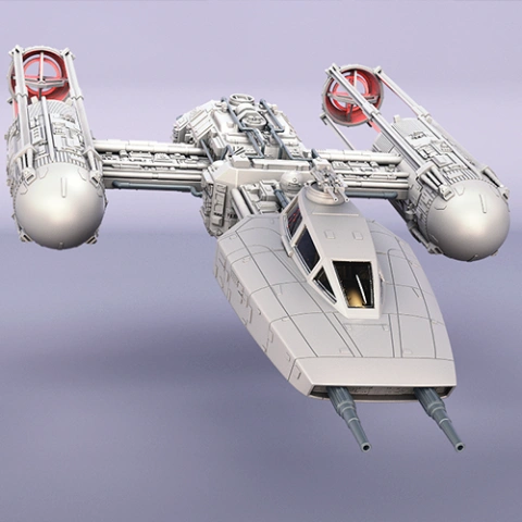
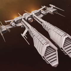
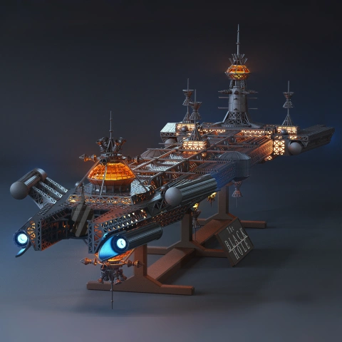
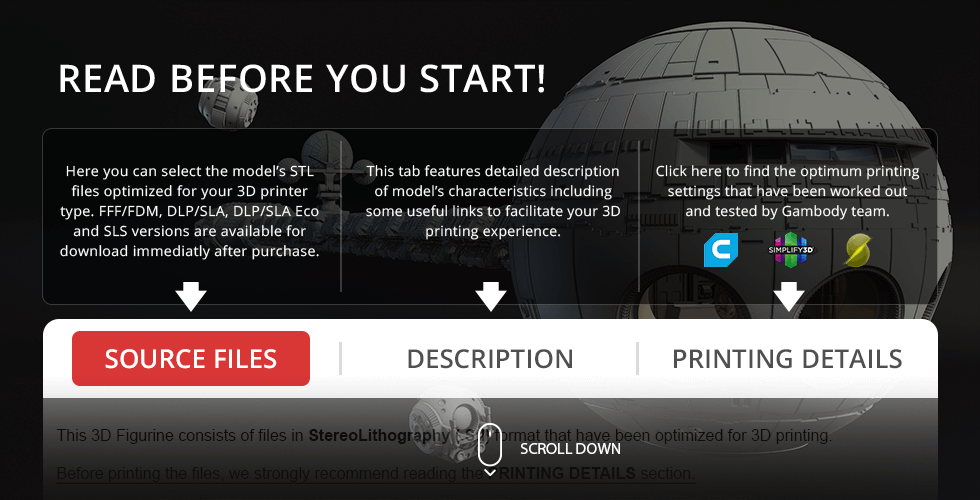
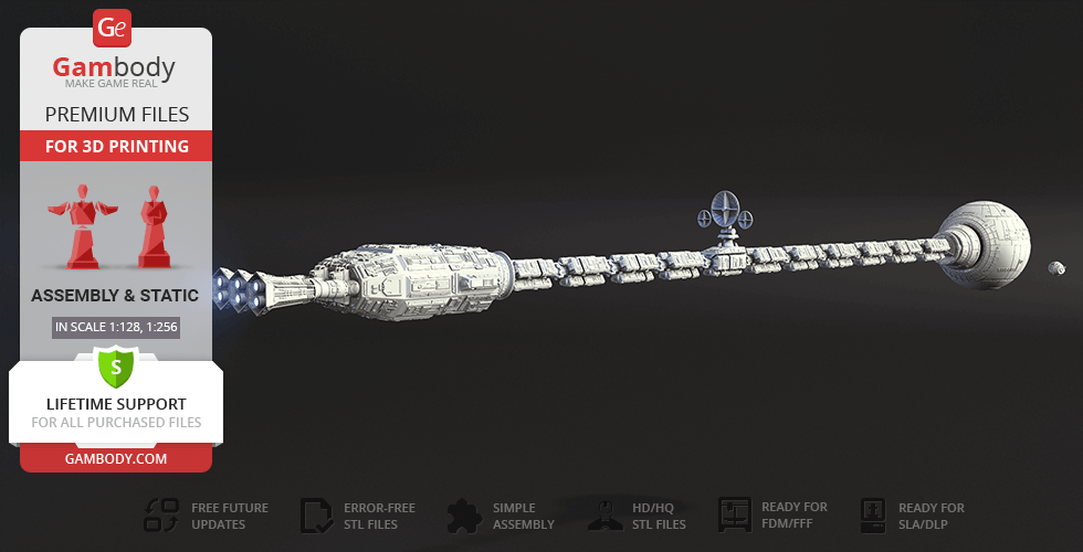
This 3D Model of the United States Spacecraft Discovery One from 2001: A Space Odyssey consists of files in StereoLithography (.Stl) format that is optimized for 3D printing.
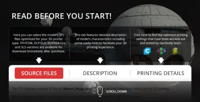
Before printing the files, we strongly recommend reading the PRINTING DETAILS section.
WHAT WILL YOU GET AFTER PURCHASE?
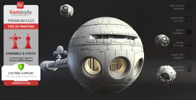
- 2 versions of Discovery One STL files for FFF/FDM and DLP/SLA - files for all versions are available for download after the purchase
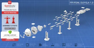
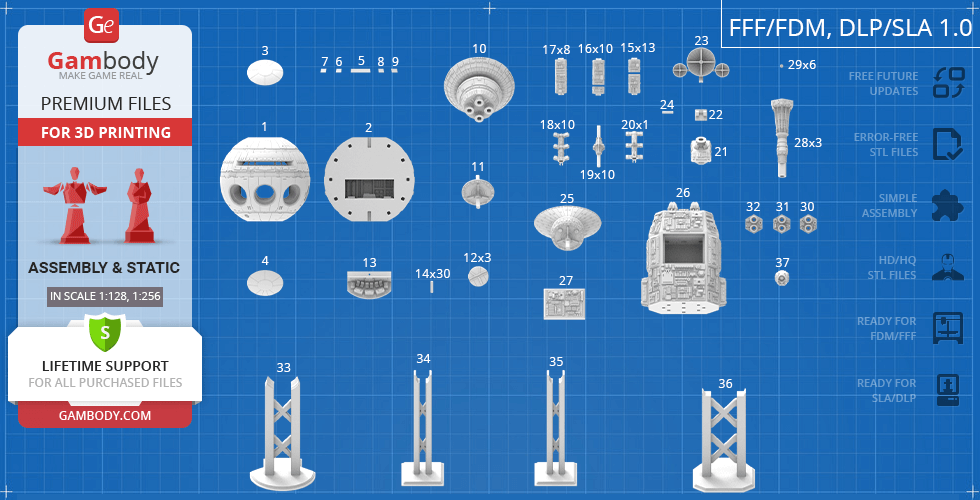
- STL files of high-poly Discovery I 3D Model for 3D printing consist of 74 parts
- Sizes:
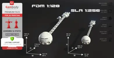
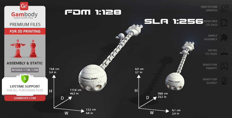
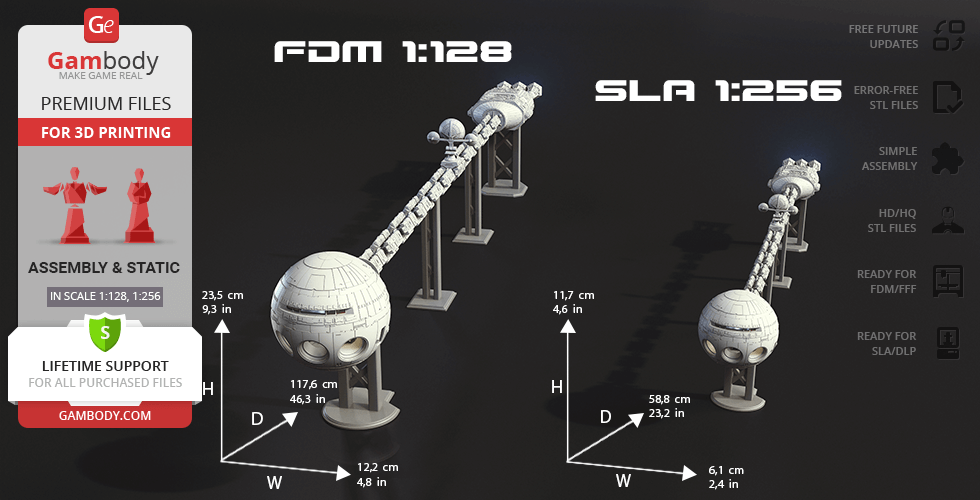
FFF/FDM: 138 mm tall, 122 mm wide, 1176 mm deep
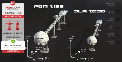
FFF/FDM (on the stand): 235 mm tall, 122 mm wide, 1176 mm deep
DLP/SLA: 69 mm tall, 61 mm wide, 588 mm deep
DLP/SLA (on the stand): 117 mm tall, 61 mm wide, 588 mm deep
- Assembly Manual for FFF/FDM 1.0 and DLP/SLA 1.0 versions in PDF format
- Detailed settings that we provide as a recommendation for Cura, Simplify3D, Slic3r and PrusaSlicer for the best print
- Full technical support from the Gambody Support Team
Detailed information about this 3D printing model is available in the DESCRIPTION section.
Before printing, take a look at Printing Details for recommended settings and tips to achieve better results.
ABOUT THIS 3D MODEL
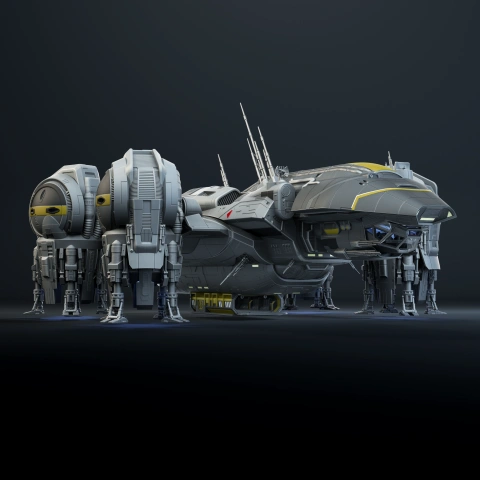
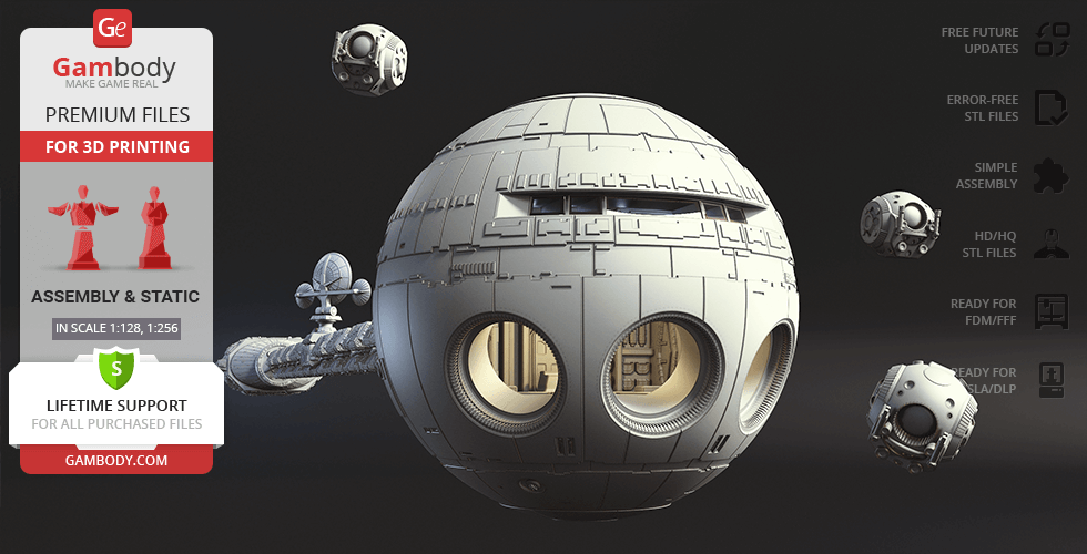
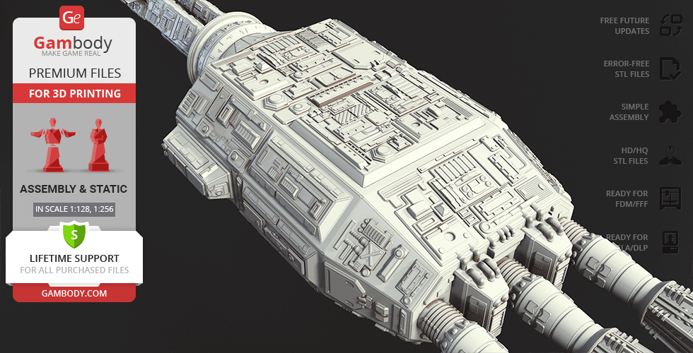
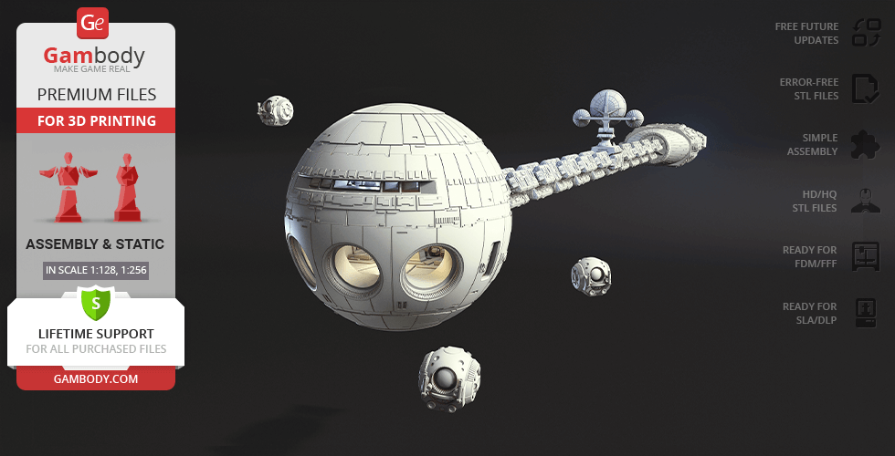
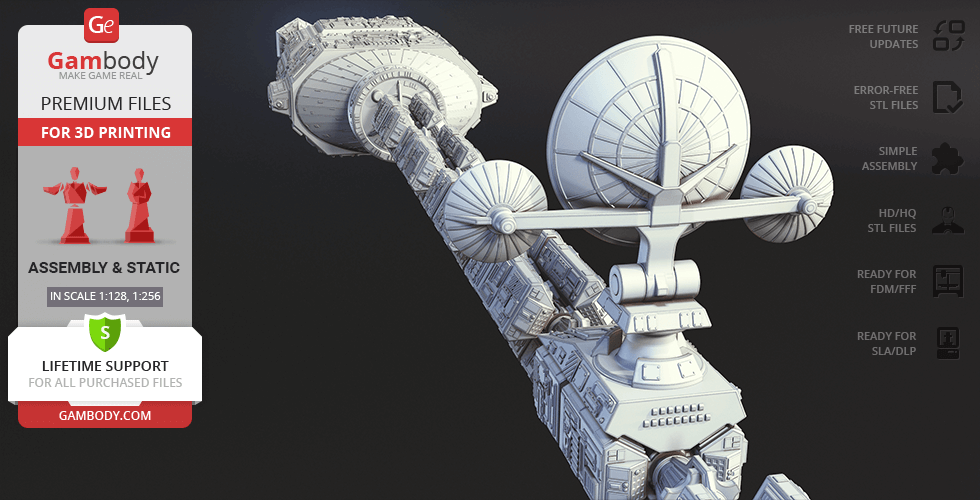
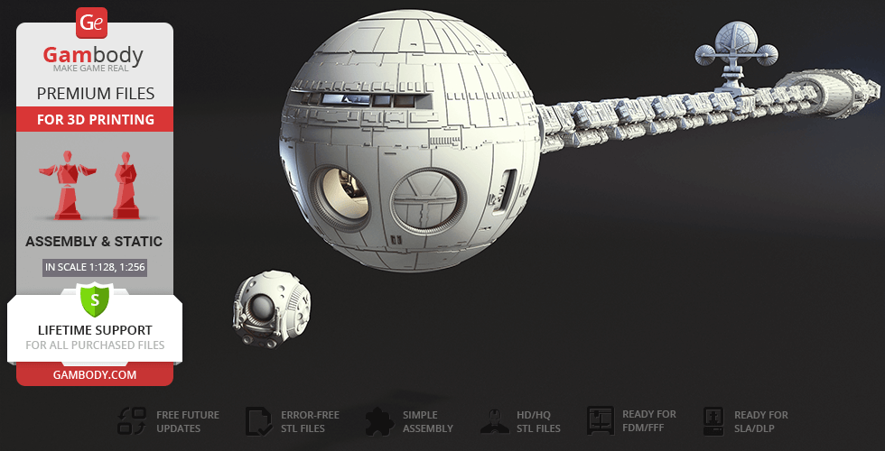
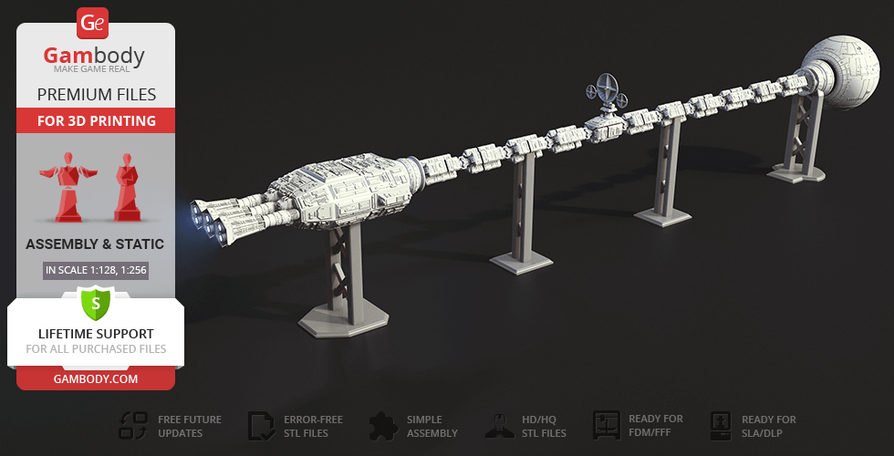
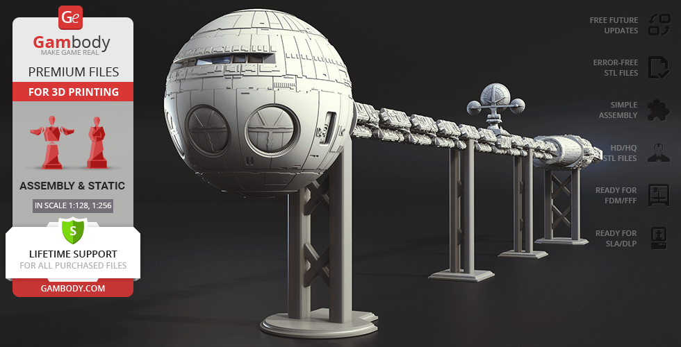
2001: A Space Odyssey masterly crafted by Clarke and Kubrick immerses you into an otherworldly experience. Despite the lack of computing power and modern CGI, the sci-fi motion picture remains just as mesmerising today thanks to the genius directing and thoughtful approach to the visuals. To embark on this existential journey, one must board the United States Spacecraft Discovery One spaceship that can now be 3D printed in your hobby workshop.
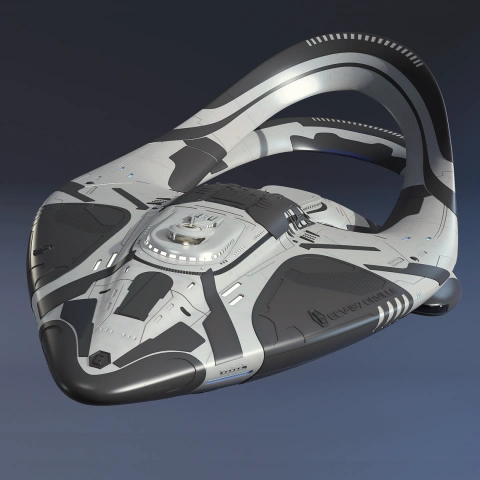
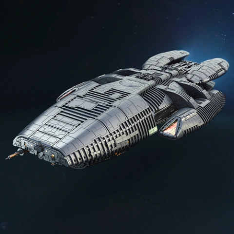
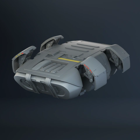
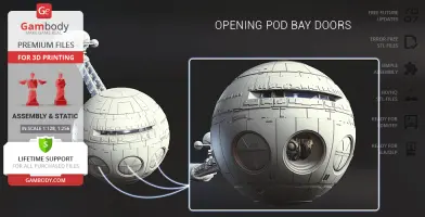
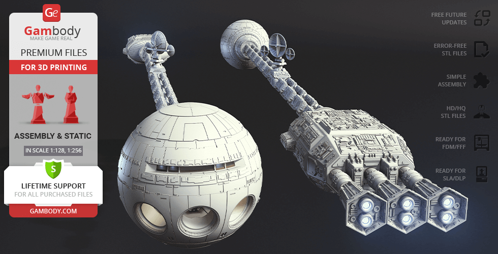
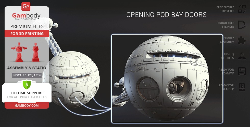
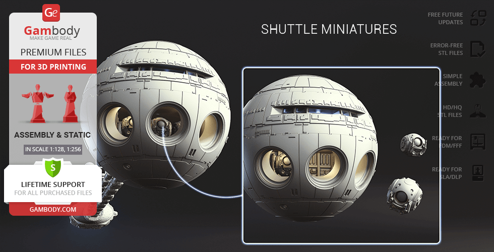
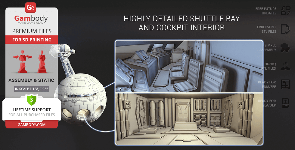
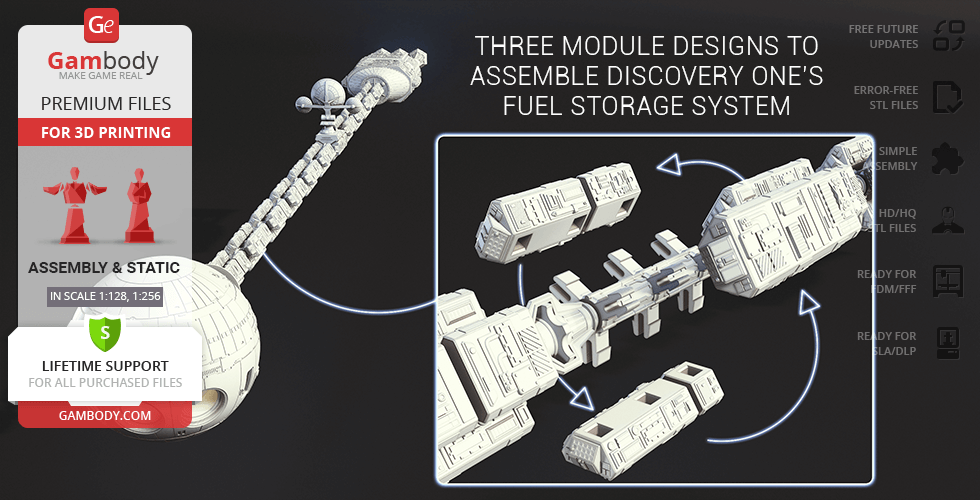
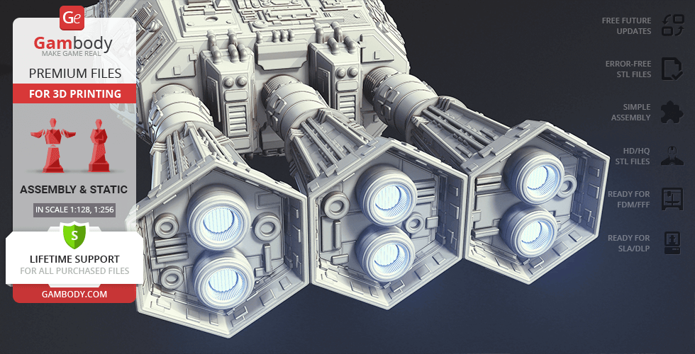
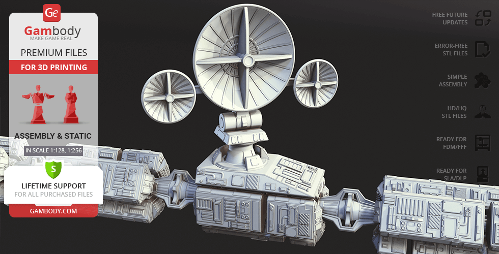
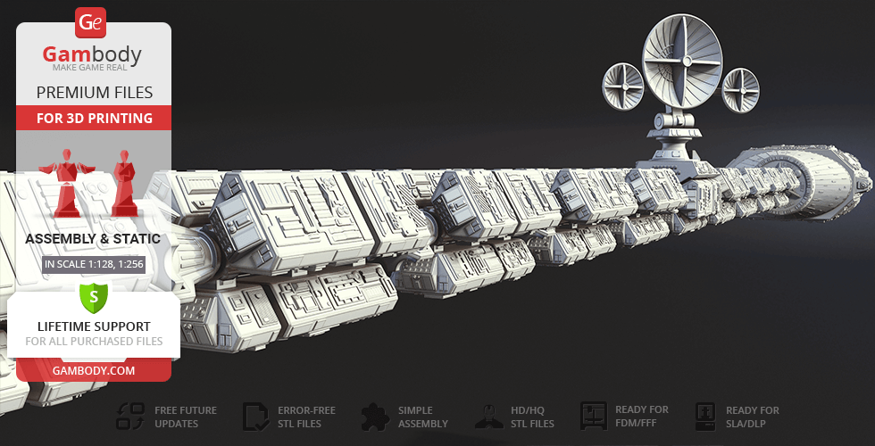
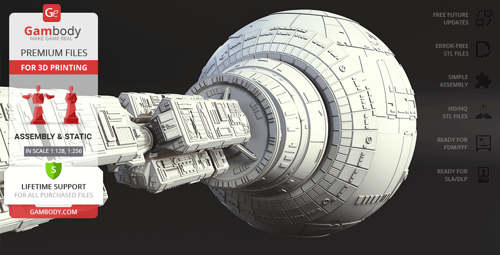
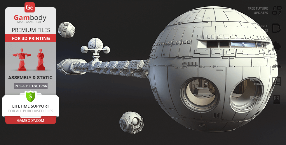
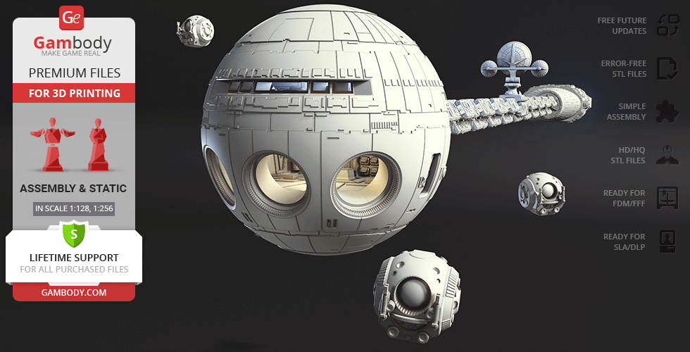
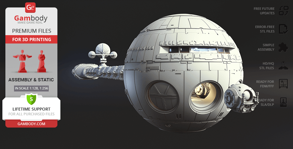
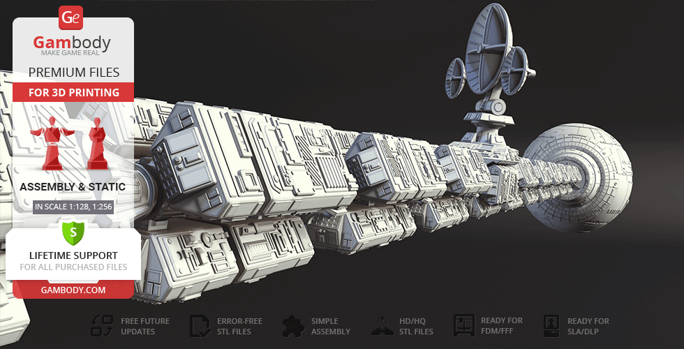
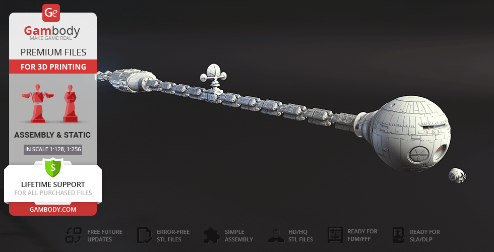
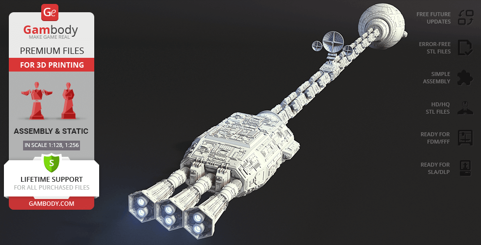
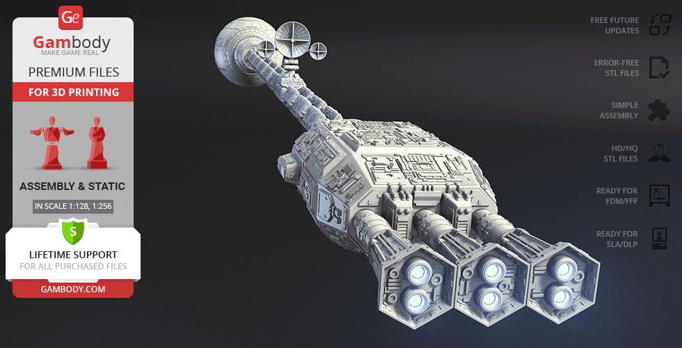
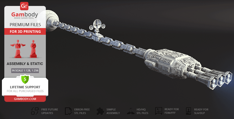
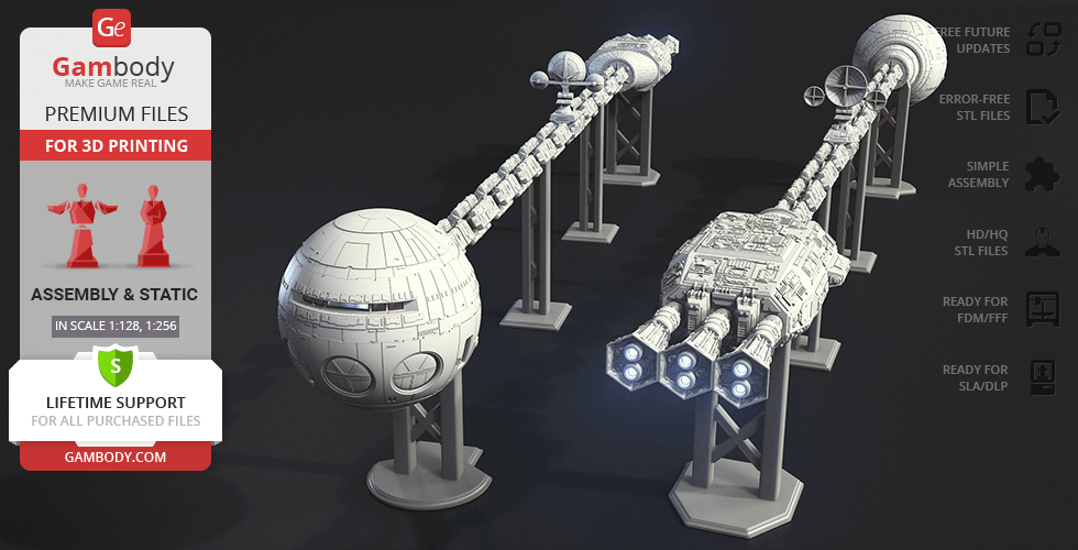
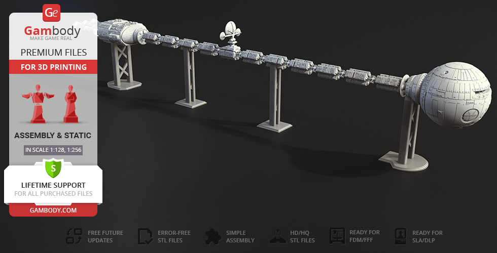
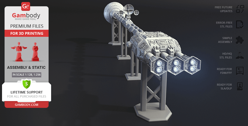
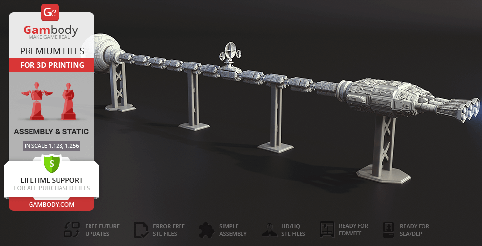
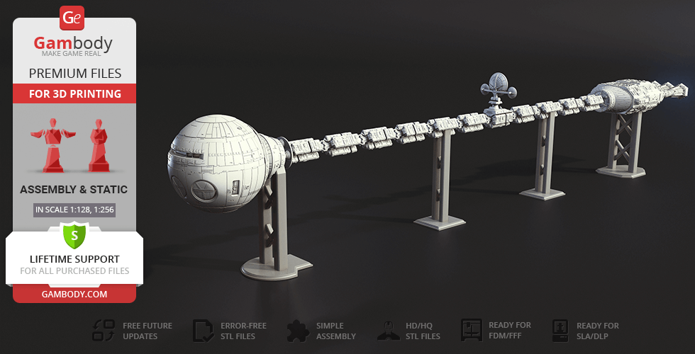
The unique Discovery One designed by our contributing 3D artist captures the peculiar construction of the immense ship. The spherical “head” of the craft contains highly detailed crew quarters, a pod bay and the small auxiliary craft you can deploy through the opening doors. The aft section with the cavradyne plasma propulsion engines is separated by a chain of tankage and structure that you can 3D print and assemble in a variety of ways. The meticulous design will charm you and encourage further explorations of our mysterious universe!
ADAPTATION FOR 3D PRINTING
Discovery One for 3D printing is a static assembly model and its moderation and adaptation for different types of 3D printers took the Gambody team 39 hours in total.
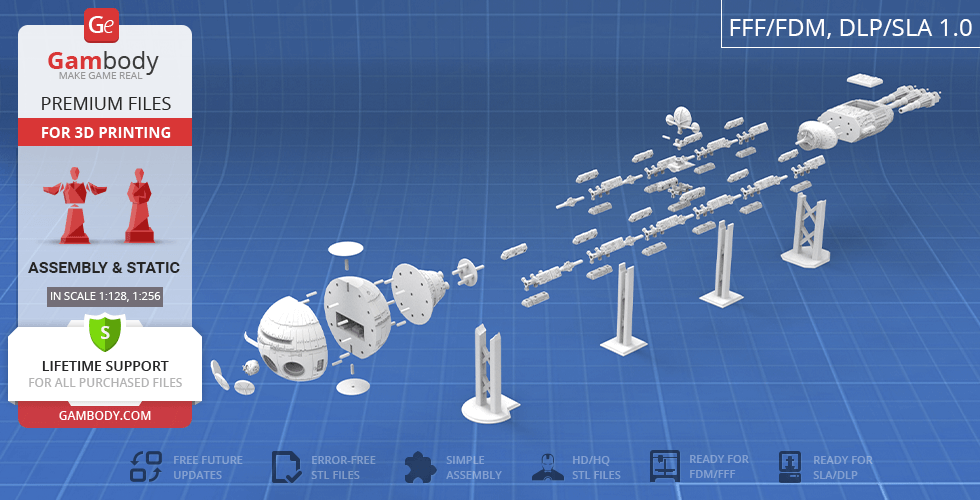
For you to receive the cleanest 3D printing result possible and minimize the amount of filament needed for generated support, the craft was divided into convenient assembly parts.
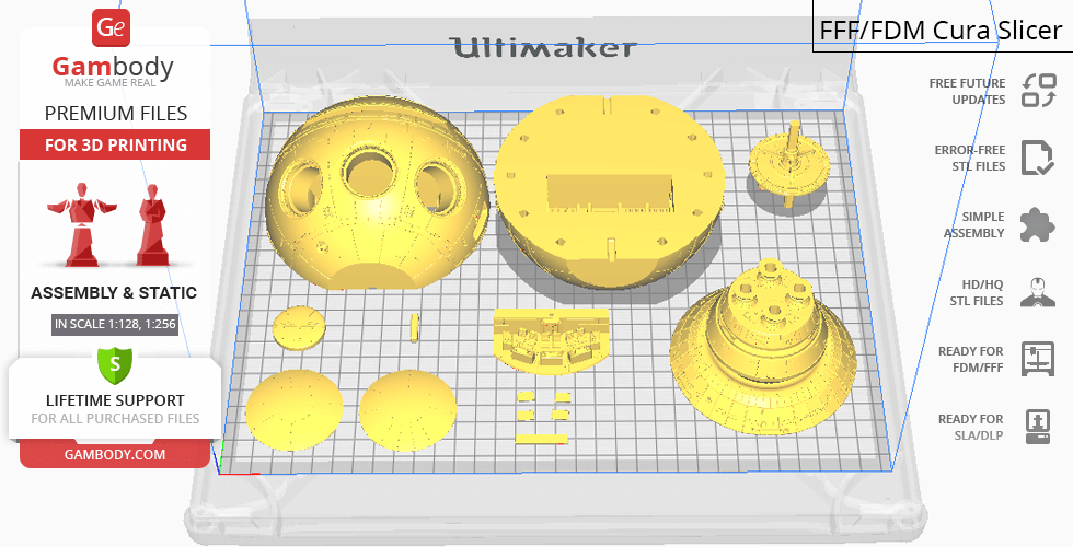
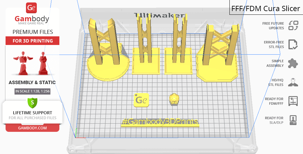
All assembly parts in the FFF/FDM 1.0 version are provided in STL files in recommended positions that were worked out in order to ensure the smoothness of the details’ surfaces after printing and that the 3D printing beginners won't face difficulties when placing the parts on a build plate. When downloading any model's file you will also receive "Assembly Manual" for FFF/FDM 1.0 and DLP/SLA 1.0 versions in PDF format. We highly recommend that you get acquainted with the “Assembly video” and "Assembly Manual" before getting down to the Discovery One model.
The model is saved in STL files, a format supported by most 3D printers. All STL files for 3D printing have been checked in Netfabb and no errors were shown.
The model’s scale was calculated from the length of the Discovery One which is 140 100 mm. The 3D printing model’s chosen scales are 1:128 for the FFF/FDM version and 1:256 for the DLP/SLA version.
VERSIONS' SPECIFICATIONS
FFF/FDM 1.0 version features:
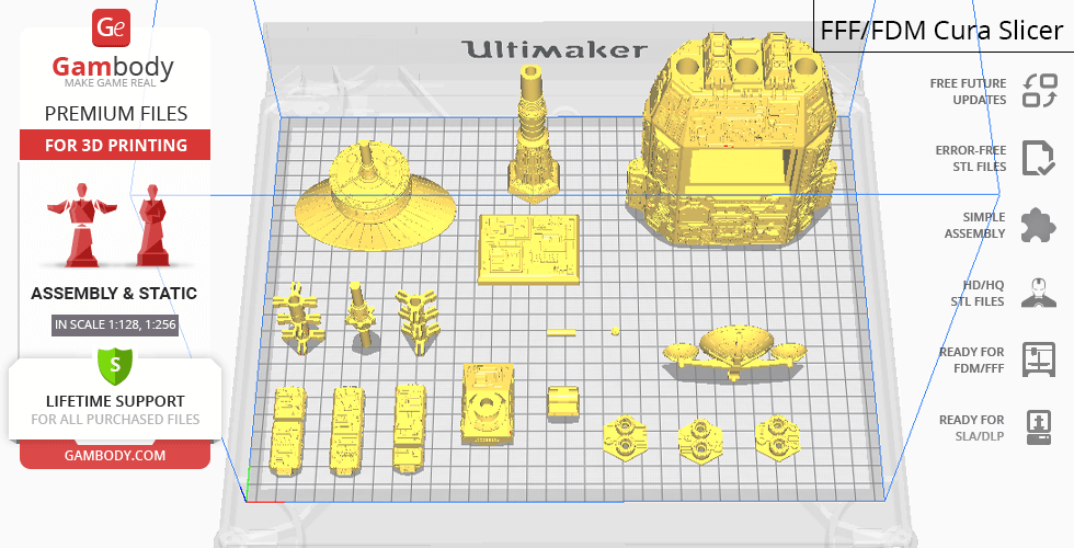
- Contains 37 parts;
- A printed model is 138 mm tall, 122 mm wide, 1176 mm deep;
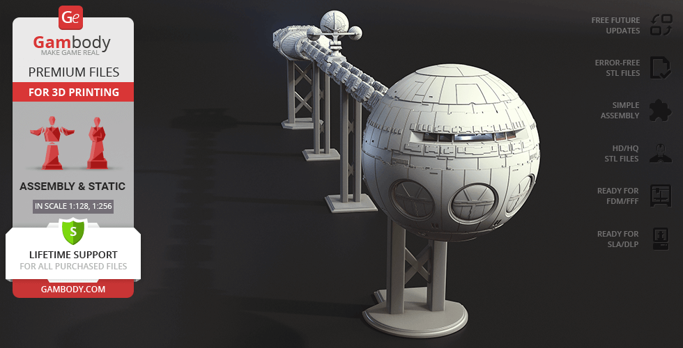
- A printed model on the stand is 235 mm tall, 122 mm wide, 1176 mm deep;
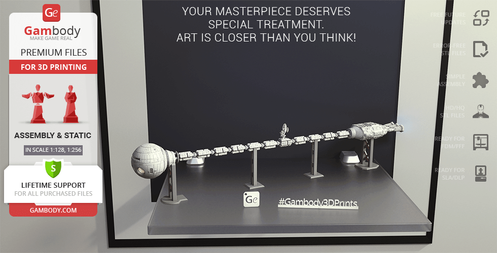
- You can assemble Discovery One’s fuel storage system using three module designs that can be arranged in any order;
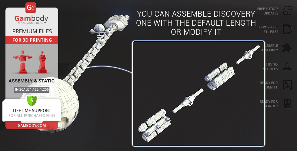
- You can assemble Discovery One with the default length or modify it;
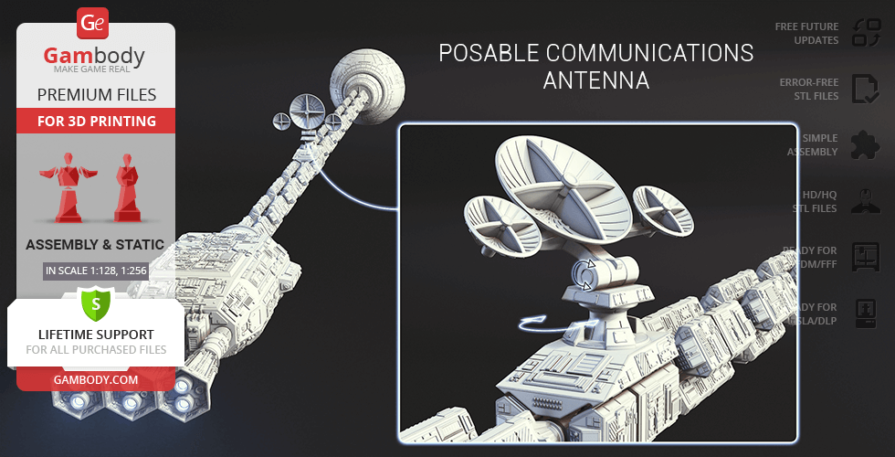
- Posable communications antenna;
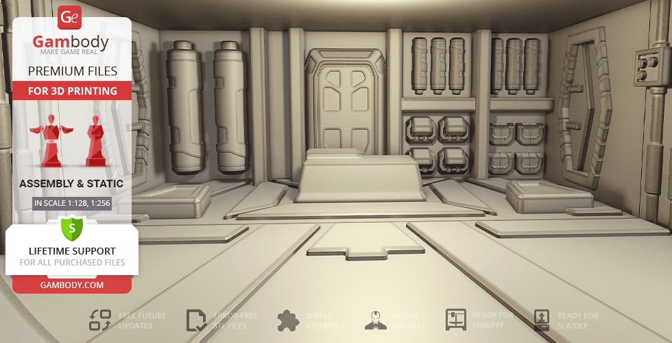
- Highly detailed shuttle bay and cockpitinterior;
- Opening pod bay doors;
- Shuttle miniatures can be placed inside the bay;
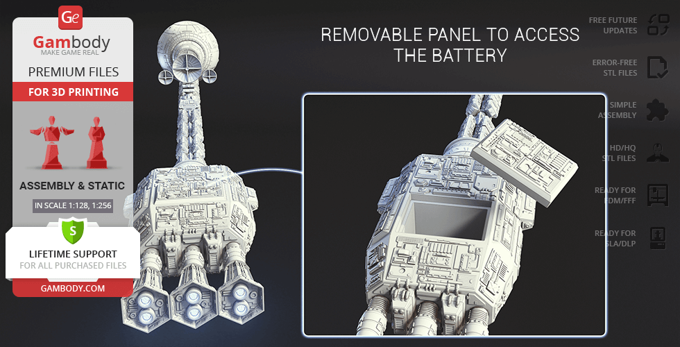
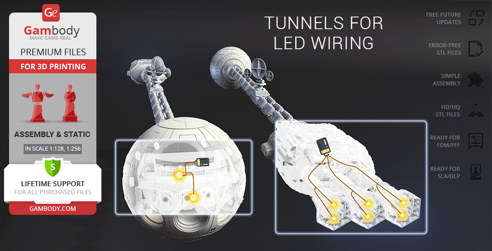
- Tunnels for LED wiring are provided to light up the cockpit, shuttle bay, and propulsion engines; the battery can be stored in the hidden compartment in the command module and behind the removable panel in the tail of the craft;
- The control deck windows and engine covers are provided as separate assembly parts to be printed using transparent material;
- All parts are divided in such a way that you will print them with the smallest number of support structures.
DLP/SLA 1.0 version features:
- Contains 37 parts;
- A printed model is 69 mm tall, 61 mm wide, 588 mm deep;
- A printed model on the stand is 117 mm tall, 61 mm wide, 588 mm deep;
- You can assemble Discovery One’s fuel storage system using three module designs that can be arranged in any order;
- You can assemble Discovery One with the default length or modify it;
- Posable communications antenna;
- Highly detailed shuttle bay and cockpitinterior;
- Opening pod bay doors;
- Shuttle miniatures can be placed inside the bay;
- Tunnels for LED wiring are provided to light up the cockpit, shuttle bay, and propulsion engines; the battery can be stored in the hidden compartment in the command module and behind the removable panel in the tail of the craft;
- The control deck windows and engine covers are provided as separate assembly parts to be printed using transparent material;
- All parts are divided in such a way to fit the build plates and to ensure that support structures are generated where needed.
You can get the model of Discovery One for 3D Printing immediately after the purchase! Just click the green Buy button in the top-right corner of the model’s page. You can pay with PayPal or your credit card.
Watch the tutorial on how to assemble Discovery One 3D Printing Model on Gambody YouTube channel.
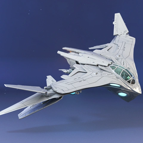
Also, you may like other Space Ships models for 3D printing.
_______
FAQ:
Where can I print a model if I have no printer?
How to get started with 3D printing?
How to set up my 3D printer?
How to choose right 3D model print bed positioning?
How to paint printed figurine?
Average customer rating (4 reviews)
4
Ratings breakdown
Click a star rating to filter reviews
Overall experience
Level of detail in the model
4
Model cut quality and assembly guide
4
Clarity and accuracy of the model page
4
Level of detail in the model
4
Model cut quality and assembly guide
4
Clarity and accuracy of the model page
4
Level of detail in the model
3
Model cut quality and assembly guide
3
Clarity and accuracy of the model page
3
Level of detail in the model
4
Model cut quality and assembly guide
4
Clarity and accuracy of the model page
4
Level of detail in the model
5
Model cut quality and assembly guide
5
Clarity and accuracy of the model page
5
To avoid printing issues and achieve the best quality, we highly recommend applying the following settings:
Generic
Below you can find printing recommendations for Cura, Bambu Lab, Simplify3D, Slic3r and PrusaSlicer software.
Disclaimer: The following printing settings are a recommendation, not an obligation. The parameters can vary depending on the peculiarities of your 3D printer, the material you use, and especially the particular assembly part you are working with. Each part that any model comprises often needs preliminary review, and you are free to tweak the settings the way you find suitable.
Note:
You can scale up the model (downscaling for FFF/FDM 3D printers is not recommended!);
All connectors should be printed at 100% Infill.
Bambu Lab printing recommendations:
These basic 3D printing settings recommendations for beginners were tested in Bambu Studio 1.9.1. Test models were printed on the Bambu Lab A1, Bambu Lab A1 Mini, Creality Ender 3 S1, Anycubic Kobra 2, and Anycubic Vyper using PLA and PETGfilaments.
To avoid printing problems, we recommend the following settings:download
Cura printing recommendations:
These are averaged settings which were tested in the Cura 5.2.1 slicer. Test models were printed on Anycubic Vyper, Creality Ender 3 Pro with PLA filament.
To avoid printing problems, we recommend the following settings:download
Simplify3D printing recommendations:
These are averaged settings which were tested in the Simplify3D 5.0.0 slicer. Test models were printed on Anycubic Vyper, FLSUN v400, Ender3 S1 with PLA filament.
To avoid printing problems, we recommend the following settings:download
Slic3r printing recommendations:
These basic 3D printing settings recommendations for beginners were tested in Slic3r 1.3.0 software. Test models were printed on Ultimaker 2, Creality Ender 3, Creality Cr-10S pro v2, Anycubic I3 Mega, Anycubic I3 MegaS, Anycubic Vyper with PLA and PetG filaments.
To avoid printing problems, we recommend the following settings:download
PrusaSlicer printing recommendations:
These basic 3D printing settings recommendations for beginners were tested in PrusaSlicer 2.3.1. Test models were printed on Ultimaker 2, Creality Ender 3, Creality Cr-10S pro v2, Anycubic I3 Mega, Anycubic I3 MegaS, Anycubic Vyper with PLA and PETG filaments.
To avoid printing problems, we recommend the following settings:download