


Files
3D model format
Stereolithography (.stl)
Total files
Slicer settings
Mesh error check
Netfabb
Support
Lifetime support from Gambody team
Update requests
Available to verified buyers
Model complexity
Advanced: may require tuning print settings or support placement, plus precise fitting, gluing, or sanding.
Model versions
FFF/FDM
Assembly method
not specified
Features
DLP/SLA
Assembly method
not specified
Features
FFF/FDM
Assembly method
not specified
Features
DLP/SLA
Assembly method
not specified
Features
Additional details
Part of diorama
Yes
Other model in diorama
Special pack included
You will get instant access to the STL files of Eagle Transporter 3D Printing Model | Assembly + Active after completing your purchase. Simply add the model to your cart and check out using PayPal, credit or debit card, Apple Pay, Google Pay, Alipay, or other available payment methods.
Watch the assembly video for Eagle Transporter 3D Printing Model | Assembly + Active, and explore more tutorials, behind-the-scenes content, 3D printing timelapses, and painting guides on the official Gambody YouTube channel.
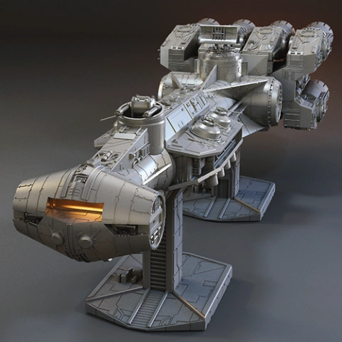
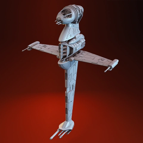
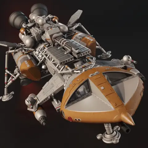
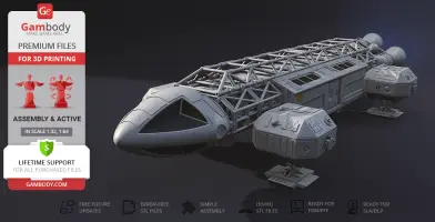
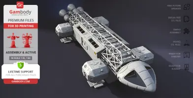
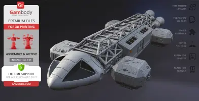
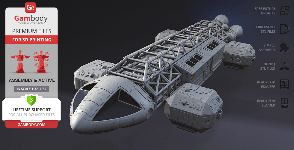
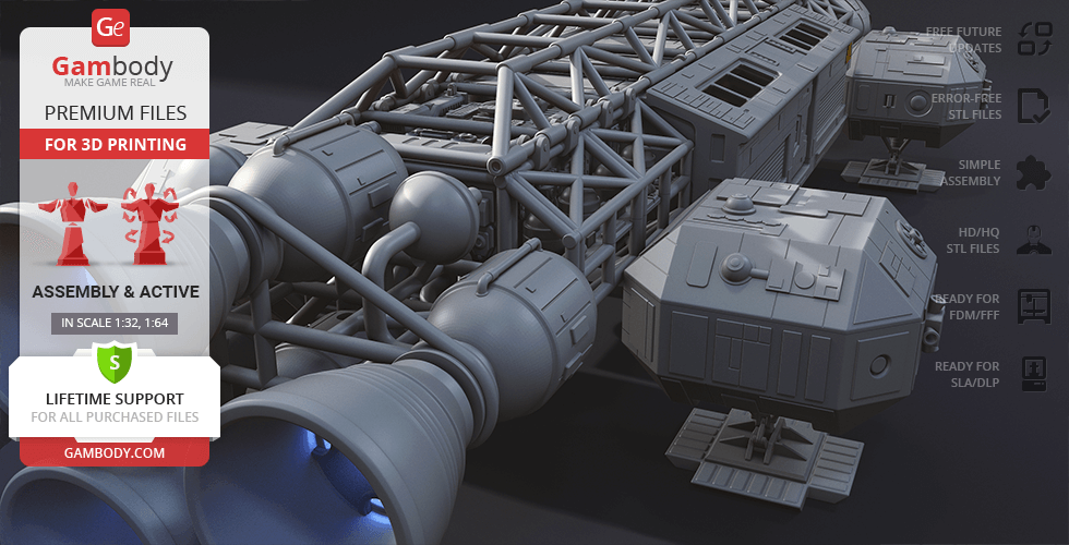
This 3D model of Eagle Transporter inspired by Space: 1999 TV show consists of files in StereoLithography (.Stl) format that is optimized for 3D printing.
Before printing the files, we strongly recommend reading the PRINTING DETAILS section.
WHAT WILL YOU GET AFTER PURCHASE?
- 4 versions of the Transporter Eagle STL files for FFF/FDM, DLP/SLA 3D printers - files for each version are available for download after the purchase
- STL files of high-poly Type A Eagle 3D Model for 3D printing consist of 286 parts
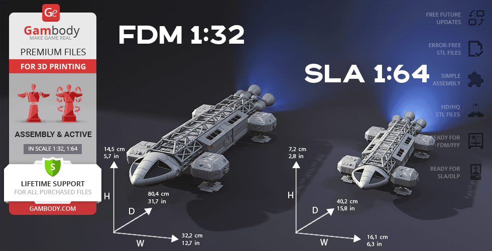
- Sizes:
- FFF/FDM: 145 mm tall, 322 mm wide, 804 mm deep
- DLP/SLA: 72 mm tall, 161 mm wide, 402 mm deep
- Assembly Manual for FFF/FDM and DLP/SLA versions in PDF format
- Detailed settings that we provide as a recommendation for Cura, Simplify3D and Slic3r for the best print- Full technical support from the Gambody Support Team
Detailed information about this 3D printing figurine is available in the DESCRIPTION section.
Before printing, take a look at Printing Details for recommended settings and tips to achieve better results.
ABOUT THIS 3D MODEL
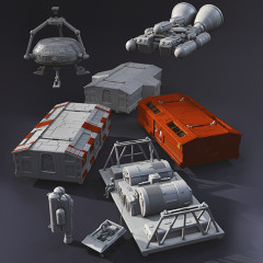
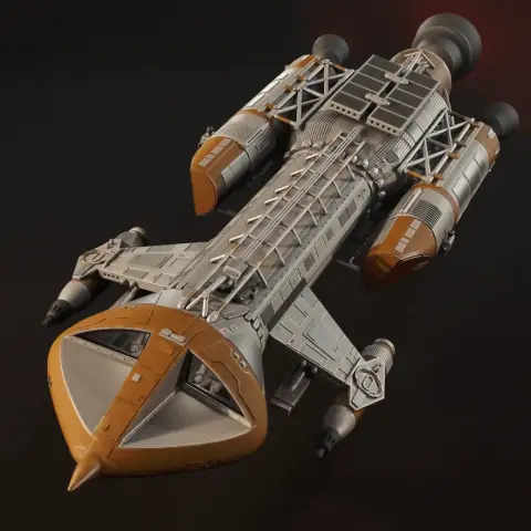
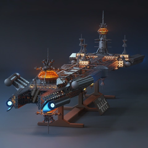
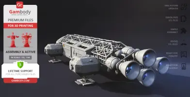
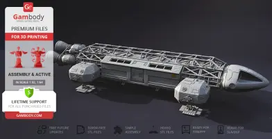
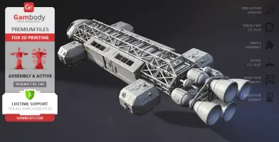
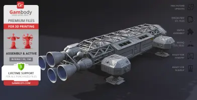
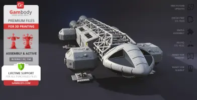
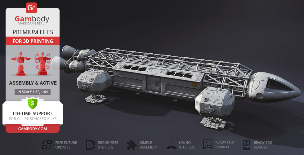
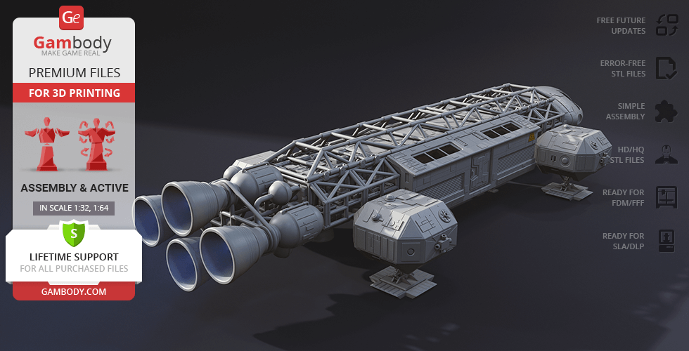
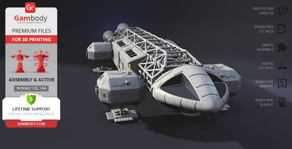
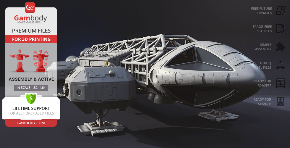
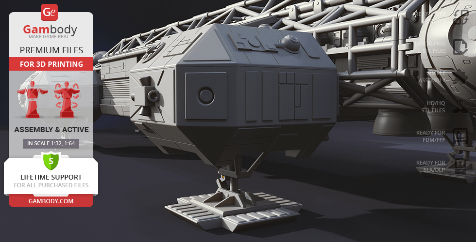
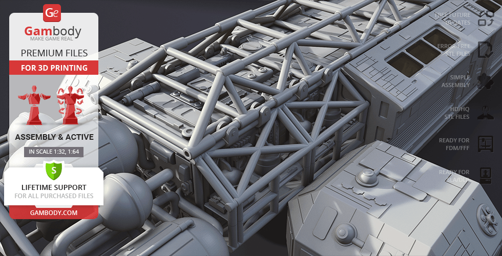
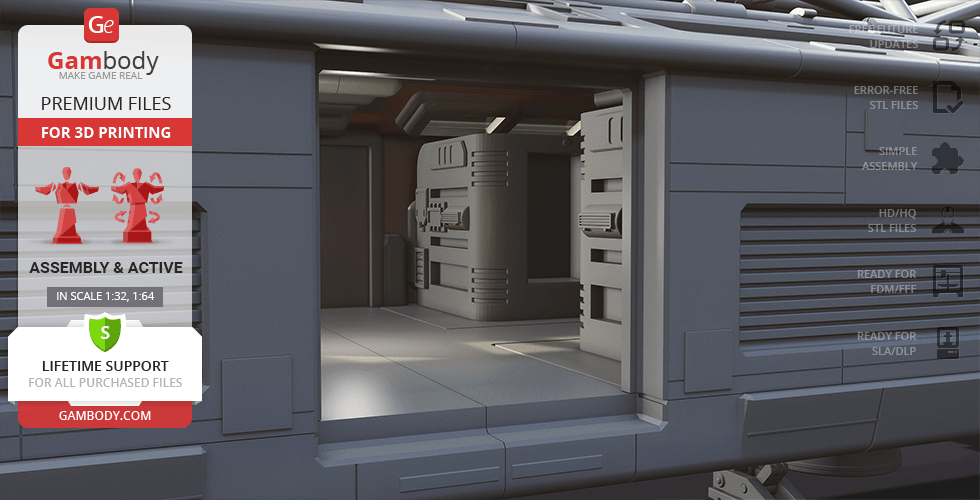
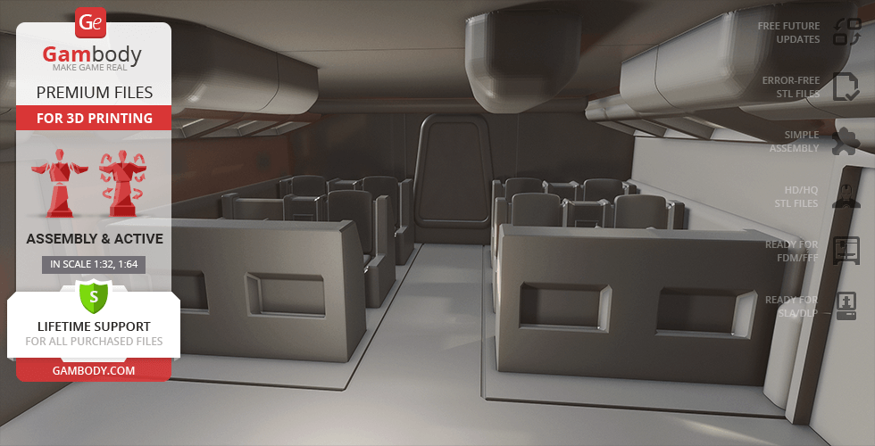
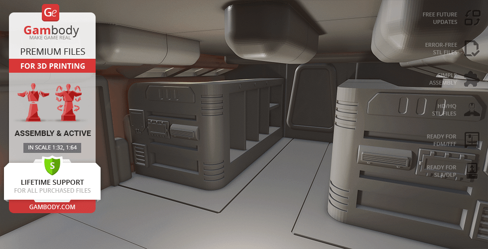
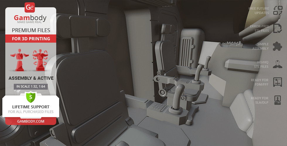
The unimaginable disaster of the thermonuclear explosion propelled the Moon away from Earth’s orbit and stranded 311 personnel of fictional Moonbase Alpha in deep space. But to their surprise, the universe started to unravel right before their eyes! Black holes, space warps, alien civilisations and unprecedented phenomena filled their journey to the ultimate destiny that we followed so closely.Take a deep dive into the enigmatic universe of Space: 1999, the most expensive sci-fi show at the time, with the Eagle Transporter space craft for 3D printing. The reliable Eagle will help you explore the secrets of the world and accommodate you comfortably - highly detailed and authentic Command and Passenger Modules are so inviting. The complex superstructure, side pods, and massive nuclear engines enhance the futuristic look of the model. 3D print the magnetic Eagle Transporter and complete any mission!
ADAPTATION FOR 3D PRINTING
Eagle Transporter for 3D printing is an active assembly model and its moderation and adaptation for different types of 3D printers took the Gambody team 45 hours in total.
For you to receive the cleanest 3D printing result possible and minimize the amount of filament needed for generated support, the Eagle Transporter was divided into convenient assembly parts. All assembly parts in the FFF/FDM 1.0 version are provided in STL files in recommended positions that were worked out in order to ensure the smoothness of the details’ surfaces after printing and that the 3D printing beginners won't face difficulties when placing the parts on a build plate. After downloading any model's file you will also receive "Assembly Manual" for FFF/FDM 1.0 and DLP/SLA 1.0 versions in PDF format. We highly recommend that you get acquainted with the “Assembly video” and "Assembly Manual" before getting down to the Eagle Transporter model.
The model is saved in STL files, a format supported by most 3D printers. All STL files for 3D printing have been checked in Netfabb and no errors were shown.The model’s scale was calculated from the approximate length of the Eagle Transporter - 26 000 mm. The 3D printing model’s chosen scales are 1/32 for the FFF/FDM version and 1/64 for the DLP/SLA version.
VERSIONS' SPECIFICATIONS
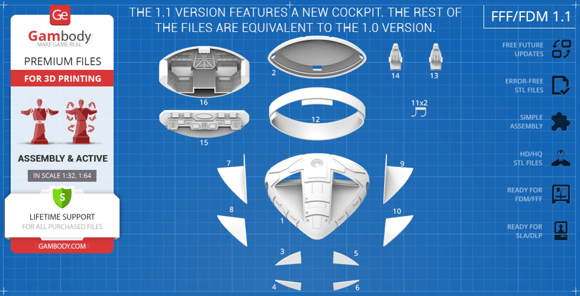
FFF/FDM 1.1 versions features:
- Contains 72 parts;
- The model has an updated cockpit;
- The new cockpit is compatible with the 1.0 version;
- All parts are divided in such a way that you will print them with the smallest number of support structures.
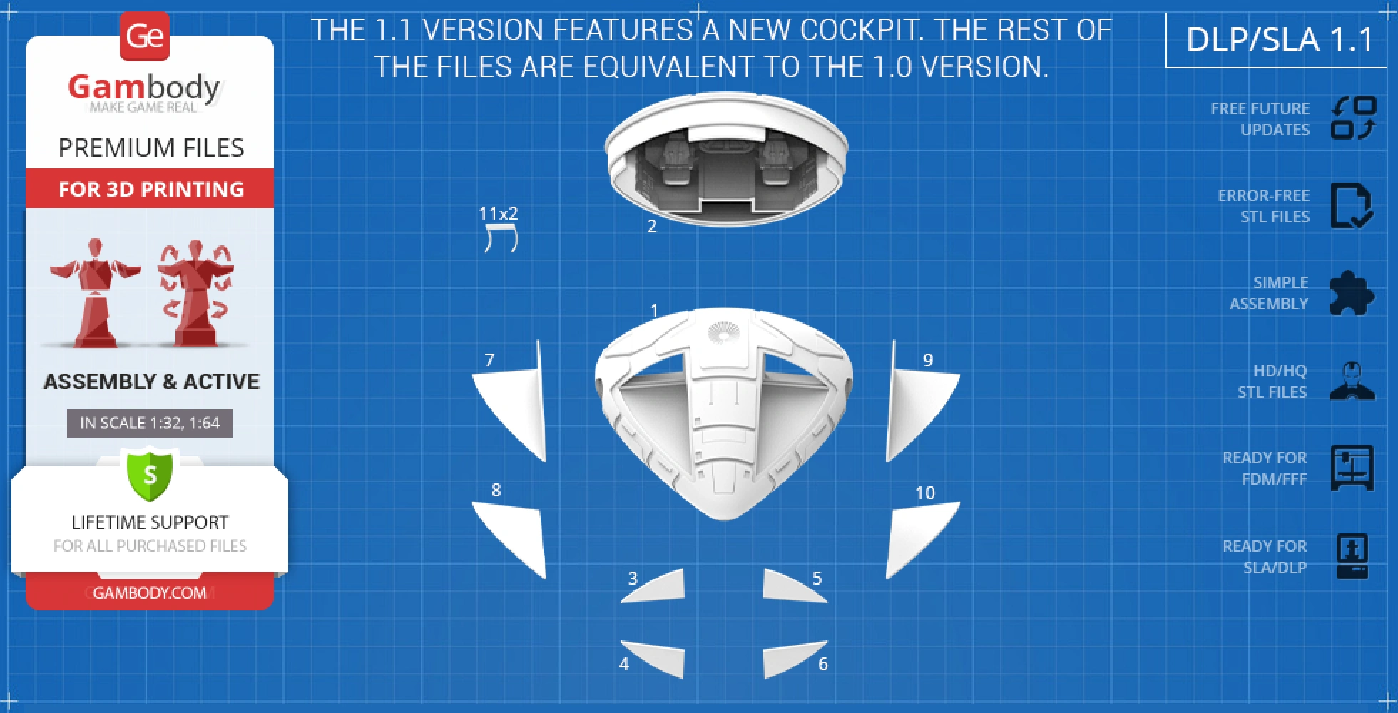
DLP/SLA 1.1 versions features:
- Contains 64 parts;
- The model has an updated cockpit;
- The new cockpit is compatible with the 1.0 version;
- All parts are divided in such a way to fit the build plates and to ensure that support structures are generated where needed.
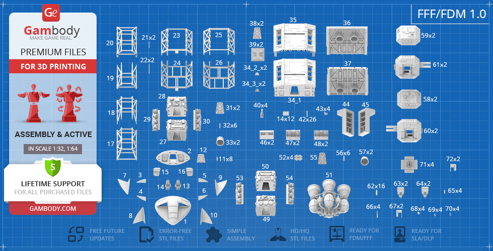
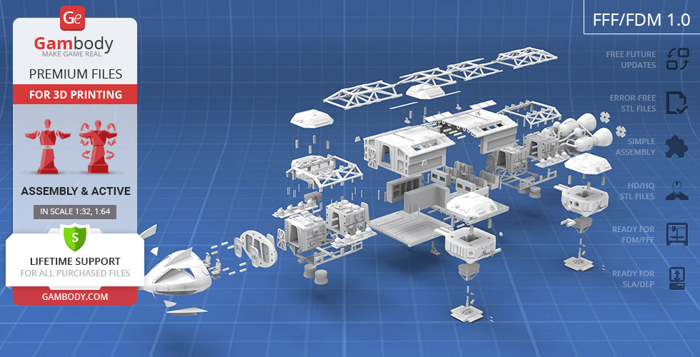
FFF/FDM 1.0 version features:
- Contains 81 parts;
- A printed model is 145 mm tall, 322 mm wide, 804 mm deep;
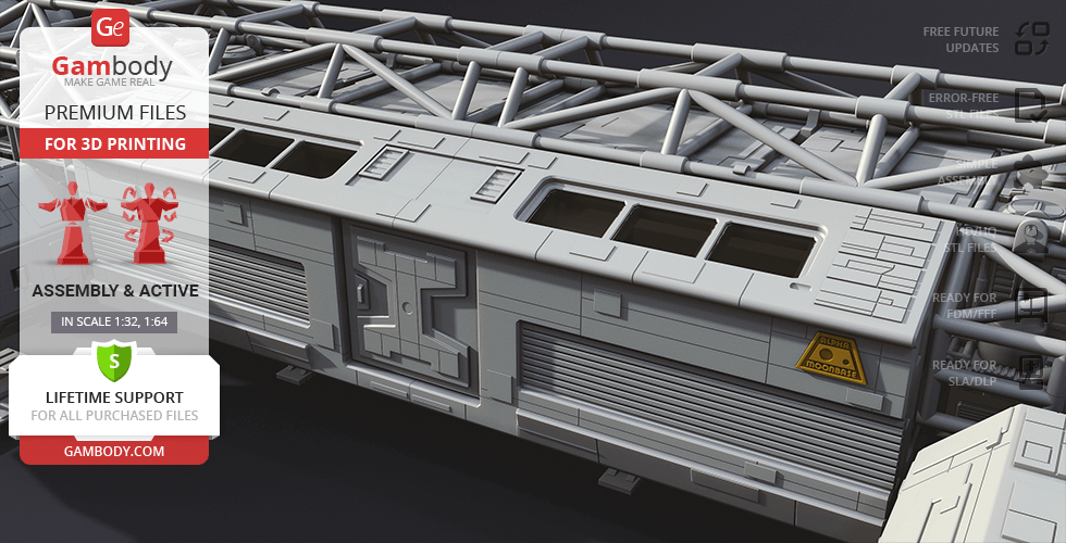
- Highly detailed Command Module;- Authentic Passenger Module;
- The Command and PassengerModules can be detached;
- ThePassenger Module can be disassembledtodisplay the interior;
- Removable door on the Passenger Module;
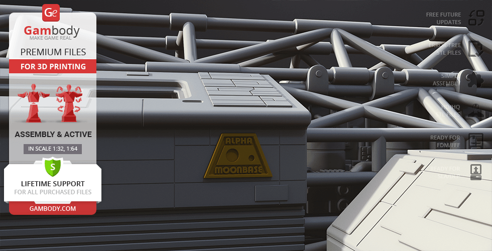
- You can assemble the Passenger Module with and without the “Moonbase Alpha” logo;
- Retractable Side Pods’ landing gear that can be fixed in your chosen position with a pin;
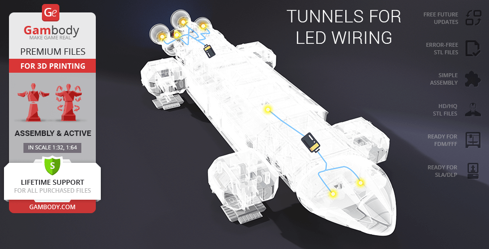
- LED wiring possibilities for the Nuclear Engines, Command and Passenger Module interior; the batteries can be stored in the hidden compartments in the head and tail of the craft;
- The windows are provided as separate assembly parts to be printed with transparent material;
- All parts are divided in such a way that you will print them with the smallest number of support structures.
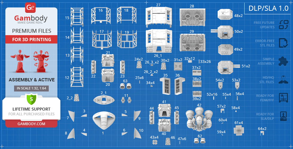
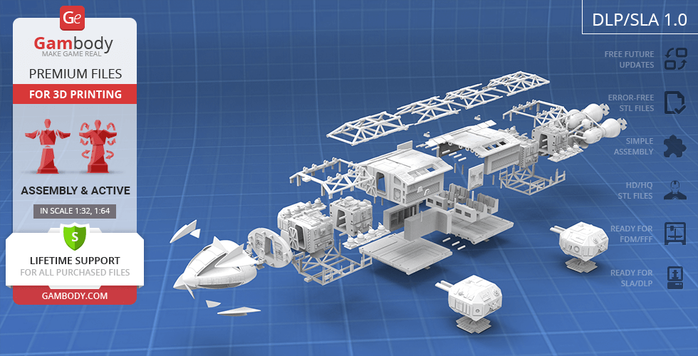
DLP/SLA 1.0 version features:
- Contains 69 parts;
- A printed model is 72 mm tall, 161 mm wide, 402 mm deep;
- Highly detailed Command Module;- Authentic Passenger Module;
- The Command and PassengerModules can be detached;
- ThePassenger Module can be disassembledtodisplay the interior;
- Removable door on the Passenger Module;
- You can assemble the Passenger Module with and without the “Moonbase Alpha” logo;
- Retractable Side Pods’ landing gear that can be fixed in your chosen position with a pin;
- LED wiring possibilities for the Nuclear Engines, Command and Passenger Module interior; the batteries can be stored in the hidden compartments in the head and tail of the craft;
- The windows are provided as separate assembly parts to be printed with transparent material;
- All parts are divided in such a way to fit the build plates and to ensure that support structures are generated where needed.
You can get the model of Eagle Transporter for 3D Printing immediately after the purchase! Just click the green Buy button in the top-right corner of the model’s page. You can pay with PayPal or your credit card.
Watch the tutorial on how to assemble Eagle Transporter 3D Printing Model at Gambody YouTube channel.
Also, you may like other Fiction models and Space Ships for 3D Printing.
_______
FAQ:
Average customer rating (23 reviews)
4.7
Ratings breakdown
Click a star rating to filter reviews
Overall experience
Level of detail in the model
4.7
Model cut quality and assembly guide
4.6
Clarity and accuracy of the model page
4.7
Level of detail in the model
4.6
Model cut quality and assembly guide
3.6
Clarity and accuracy of the model page
4.7
Overall very nice model, do wish the thruster pods on the sides were not attached, but otherwise no real complaints at all.
Weathering and decals not done yet, but otherwise finished, if a model is ever really finished.
We have passed your comment about the side thruster pods along to the model’s author, Leo Martel, for consideration.
Thank you again for sharing your build with us.
Level of detail in the model
5
Model cut quality and assembly guide
5
Clarity and accuracy of the model page
5
Here’s a great example from Mark Bendall, who printed the Eagle Transporter on their Elegoo Saturn and shared it in our Facebook community:
https://www.facebook.com/groups/183216945475583/posts/1618108635319733
Feel free to join the community as well and share your progress—we’d be happy to have you on board!
Pro tip: if you find some parts from the resin (DLP/SLA) version easier to print or assemble, you can try scaling them up to 200% and matching them with the FFF/FDM files. You might find that cutting method more convenient! Just be sure the scaled-up parts will still fit your printer’s build volume.
And of course, feel free to reach out to us anytime at support@gambody.com if you have questions or need assistance with your project.
Level of detail in the model
4.5
Model cut quality and assembly guide
3.5
Clarity and accuracy of the model page
4.6
Just need to print decals and do the final weathering and this one will be done. Lots of crazy printing in this one, but nothing too crazy.
Level of detail in the model
5
Model cut quality and assembly guide
5
Clarity and accuracy of the model page
4.2
1) Come avete stampato tutte le finestre? In ABS trasparente? Io non ci sono riuscito, credo le autoprodurrò con del plexiglass.
2) Che ne dite di aggiungere un paio di piloti?
Regarding the window parts in the Eagle Transporter 3D Model, they do play an important visual role, and there are a few good approaches you can choose from. You can print and post-process the windows using transparent PETG, clear resin, or another clear material you’re comfortable working with. That said, to be completely honest, FFF/FDM printing cannot achieve true optical clarity in the same way resin printing can. Even with careful tuning and post-processing, the result is usually translucent rather than fully clear.
Because of this, many experienced makers choose an alternative solution: cutting the windows from clear PVC or plexiglass sheets. This method often gives the most realistic result and is a very popular choice for this model.
For more detailed tips and step-by-step techniques on working with clear parts, you may find this article helpful:
https://www.gambody.com/blog/tips-for-making-clear-3d-prints-in-transparent-filament-and-resin/
As for adding pilots, that’s a great idea and something many hobbyists like to do for extra realism. There is a compatible pilot available in the Eagle Transporter Add-On Kit, which you can find here: https://www.gambody.com/premium/moon-base-space-1999
If you have any further questions, feel free to reach out — we’re always happy to help.
Level of detail in the model
1.9
Model cut quality and assembly guide
1.8
Clarity and accuracy of the model page
1.2
In many cases, this type of issue is related to material behavior or printer calibration rather than the model geometry itself. FDM prints can be sensitive to factors such as extrusion calibration, wall thickness, flow rate, and material shrinkage, all of which may affect how precisely parts fit together.
To help us look into this more accurately, could you please let us know:
- Which printer model and material you’re using
- Whether your printer is properly calibrated; we recommend running a calibration test print, such as these calibration cubes: https://www.gambody.com/premium/calibration-elements-3d-printer
- Whether the model was scaled, and if so, whether the same scale factor was applied consistently to all parts
- Which specific parts are not fitting as expected
Photos of the issue would also be very helpful, if possible.
We’d also like to note that version 1.1 of the model, which includes an updated cockpit, is available.
Once we have a bit more detail, we’ll be happy to guide you on possible adjustments or check whether any refinements are needed. We’re here to help you achieve the best possible result with your build.
Level of detail in the model
4.8
Model cut quality and assembly guide
4.5
Clarity and accuracy of the model page
4.4
You won’t believe it, but ever since the Eagle Transporter was released on our marketplace, the Hawk Mark IX has become one of the most frequently requested follow-up models. Your vote has now been added to that growing list!
Here on Gambody, each new request helps contributing artists gauge community interest and decide which models to develop next — so your suggestion is truly appreciated. And with the amount of support this iconic ship is getting, we wouldn’t be surprised to see it appear on the marketplace in the new year.
If you ever have more ideas or dream models you'd love to see created, feel free to submit them anytime through our official request form:
https://goo.gl/forms/vcedoRHt7orI2eTZ2
Thank you for choosing Gambody — and happy printing!
Level of detail in the model
3.5
Model cut quality and assembly guide
4
Clarity and accuracy of the model page
4.5
Please note that all models on our marketplace are original creations made by Gambody's contributing 3D artists. They are not exact copies of existing items or products. Each project is also carefully adapted for optimal 3D printing by our Moderation Team, which sometimes requires design decisions that differ from the on-screen version.
At the same time, we have passed your feedback and a vote for the screen-accurate version to our Moderation Team, and it can be considered in future updates for the model. Please feel free to send us any additional reference images or info for the elements that you believe can be improved to support@gambody.com.
We appreciate your enthusiasm and input in helping us improve the Eagle Transporter 3D model to make it as accurate as possible. Please let us know if there's anything else we can assist you with!
Level of detail in the model
5
Model cut quality and assembly guide
5
Clarity and accuracy of the model page
5
Level of detail in the model
5
Model cut quality and assembly guide
5
Clarity and accuracy of the model page
5
Level of detail in the model
5
Model cut quality and assembly guide
5
Clarity and accuracy of the model page
5
Level of detail in the model
5
Model cut quality and assembly guide
5
Clarity and accuracy of the model page
5
Level of detail in the model
5
Model cut quality and assembly guide
5
Clarity and accuracy of the model page
5
Level of detail in the model
5
Model cut quality and assembly guide
5
Clarity and accuracy of the model page
5
Level of detail in the model
5
Model cut quality and assembly guide
5
Clarity and accuracy of the model page
5
Level of detail in the model
5
Model cut quality and assembly guide
5
Clarity and accuracy of the model page
5
Level of detail in the model
4
Model cut quality and assembly guide
4
Clarity and accuracy of the model page
4
Level of detail in the model
2
Model cut quality and assembly guide
2
Clarity and accuracy of the model page
2
Level of detail in the model
5
Model cut quality and assembly guide
5
Clarity and accuracy of the model page
5
Level of detail in the model
5
Model cut quality and assembly guide
5
Clarity and accuracy of the model page
5
Level of detail in the model
5
Model cut quality and assembly guide
5
Clarity and accuracy of the model page
5
Below you'll find detailed slicing settings for Bambu Studio 2.0+, Orca Slicer 2.0+, UltiMaker Cura 5.0+, PrusaSlicer 2.0+, Slic3r 1.3+, Simplify3D 5.0+ to help you get the best results when printing this model. These settings are optimized specifically for this 3D model, but please note they may need slight adjustments depending on your printer or filament. When in doubt, refer to your printer's user manual.
To avoid printing issues and achieve the best quality, we highly recommend applying the following settings:
For better quality use 0.12 mm layer height, for fast printing use 0.2 mm layer height. For pins and the Ge connectors, use 0.2 layer height.
120-150% of your Layer Height
But you can paint the seam if you want.
You have to calibrate this parameter
You have to calibrate this parameter
You have to calibrate this parameter
For pins and power elements of the structure, such as the vehicle frame, use 3 loop
Disabled for vehicles and enabled for characters
For 0,2 Layer Height
The parameters in this tab vary greatly, it all depends on the quality of your printer. For example, if you have a classic Ender3, stick to the minimum parameters, but if you have a newer printer, for example Anycubic cobra 3 v2, you can select the maximum recommended values
Settings for advanced users, change these parameters only if you have sufficient 3D printing expertise
Enable this parameter if your model requires supports
We also recommend placing and removing supports manually in some places using special button
1-2 loops for more thick support
Top Z distance = 1-1.3 layer Height. If the supports are hard to remove, try increasing this setting by 0.1-0,4 mm
Bottom Z distance = 1-1.3 layer Height. If the supports are hard to remove, try increasing this setting by 0.1-0,4 mm
You have to calibrate this parameter which one is better for your filament
Increase this parameter if the supports are hard to remove from walls
For PLA and PETG filament types
5-8 mm is optional for small prints that have bad adhesion to the build plate
You have to calibrate this parameter
Read the description on your filament roll
Read the description on your filament roll and increase this parameter for fast printers
Read the description on your filament roll and increase this parameter for fast printers
For better quality use 0.12 mm layer height, for fast printing use 0.2 mm layer height. For pins and the Ge connectors, use 0.2 layer height.
120-150% of your Layer Height
But you can paint the seam if you want.
0.01-0.05 You have to calibrate this parameter
0.01-0.05 You have to calibrate this parameter
0.1-0.2 You have to calibrate this parameter
For pins and power elements of the structure, such as the vehicle frame, use 3 loop
Disabled for vehicles and ships, enabled for characters
For 0,2 Layer Height
For 0,2 Layer Height
The parameters in this tab vary greatly, it all depends on the quality of your printer. For example, if you have a classic Ender3, stick to the minimum parameters, but if you have a newer printer, for example, Anycubic Kobra 3 Or Bambulab A1, you can select the maximum recommended values.
Settings for advanced users, change these parameters only if you have sufficient 3D printing expertise
Enable this parameter if your model requires supports
We also recommend placing and removing supports manually in some places using special button
Top Z distance = 1-1.3 layer Height. If the supports are hard to remove, try increasing this setting by 0.1-0,4 mm
Bottom Z distance = 1-1.3 layer Height. If the supports are hard to remove, try increasing this setting by 0.1-0,4 mm
Increase this parameter if the supports are hard to remove from walls
For PLA and PETG filament types
5-8 mm is optional for small prints that have bad adhesion to the build plate
Read the description on your filament roll
Read the description on your filament roll and increase this parameter for fast printers
You have to calibrate this parameter
Read the description on your filament roll and increase this parameter for fast printers
Read the description on your filament roll
This field is filled in according to your printer specifications when you add it to the slicer.
You can add custom G-code here for the start and end of the print. However, be careful - this is for advanced users only!
You have to calibrate your printer using Ge retraction test models
Retraction Length: For direct-drive setups use 0.5 mm to 2.5 mm; for Bowden extruders use 5 to 7 mm
This is how fast the filament is pulled back—40-60 mm/s for direct drive and 30-50 mm/s for Bowden setups.
You have to calibrate this parameter: Reduce it until the printer starts to hit the parts with the nozzle during printing, then increase it by 0.2.
For better quality use 0.12 mm layer height, for fast printing use 0.2 mm layer height. For pins and the Ge connectors, use 0.2 layer height.
120-150% of your Layer Height
To increase the strength of the print parts, use wall line count: 3
For pins and connectors use 50% Infill
These parameters are for standard PLA plastic. If you are using a different type of plastic, check the printing temperature recommended by the manufacturer. Also, read the description on your filament spool. For fast printers, add +30 °C to the current parameters.
The parameters in this tab vary greatly, it all depends on the quality of your printer. For example, if you have a classic Ender3, stick to the minimum parameters, but if you have a newer printer, for example Anycubic cobra 3 v3, you can select the maximum recommended values
Settings for advanced users, change these parameters only if you have sufficient 3D printing expertise.
You need to calibrate this parameter using Gambody test models. These values are average values for a Direct Drive extruder; for a Bowden extruder, the values should be increased.
You need to calibrate this parameter using Gambody test models. These values are average values for a Direct Drive extruder; for a Bowden extruder, the values should be increased.
Use this value other than 0 if your nozzle catches on the internal infill during travel moves. Try to keep this value as low as possible in height.
Use normal supports to support large, straight surfaces (most mechanical or technical parts).
You have to calibrate this parameter according to the capabilities of your printer and your filament, using a Gambody test models.
Use 1 instead of 0 if your supports are thin and tall. They will be harder to remove, but much stronger.
Top Z distance = 1-1.3 layer Height. If the supports are hard to remove, try increasing this setting by 0.1-0,4 mm
Increase this parameter if the supports are hard to remove from walls
Use tree supports to support complex objects, such as characters.
You have to calibrate this parameter according to the capabilities of your printer and your filament, using a Gambody test models.
Top Z distance = 1-1.3 layer Height. If the supports are hard to remove, try increasing this setting by 0.1-0,4 mm
Increase this parameter if the supports are hard to remove from walls
Use a skirt for all parts when printing on outdated printers.
Use a brim when printing thin but tall parts, as well as parts with a small bed adhesion area.
For better quality use 0.12 mm layer height, for fast printing use 0.2 mm layer height. For pins and the Ge connectors, use 0.2 layer height.
120-150% of your Layer Height
for 0.2 Layer Height
But you can paint the seam if you want.
(for PLA and PETG)
(5-8 mm is optional for small prints that have bad adhesion to the build plate)
Enable this parameter if your model requires supports
(45-50 degree)You have to calibrate this parameter according to the capabilities of your printer
and your filament, using a Gambody test models.
Top contact Z distance = 1-1.3 layer Height. If the supports are hard to remove, try
increasing this setting by 0.1-0,4 mm
Top contact Z distance = 1-1.3 layer Height. If the supports are hard to remove, try
increasing this setting by 0.1-0,4 mm
Increase this parameter if the supports are hard to remove from walls
The parameters in this tab vary greatly, it all depends on the quality of your printer. For example, if you have a classic Ender3, stick to the minimum parameters, but if you have a newer printer, for example Anycubic cobra 3 v3, you can select the maximum recommended values
Settings for advanced users, change these parameters only if you have sufficient 3D printing expertise. Use the minimum value for outdated printers without acceleration calibration, and the maximum value for modern printers if you need it.
These settings only work for 3D printers with multiple extruders
You can try setting all parameters in this section, except the First layer, to values between 0.75% of your nozzle diameter and 1.25% of your nozzle diameter. Adjusting them will help you work out the optimal parameters for the best quality for your print. As for the First layer, you can set it to 150% of the diameter of your nozzle for better adhesion to the build plate (for a nozzle with a diameter of 0.4 mm, the First layer extrusion width can be from 0.3 mm to 0.5 mm)
For better printing quality you have to calibrate this parameter using Gambody test model.
Check your filament manufacturer's temperature recommendations on the spool.
Cooling parameters depends on the material you use for printing.
*for PLA
For better quality use 0.12 mm layer height, for fast printing use 0.2 mm layer height. For pins and the Ge connectors, use 0.2 layer height.
120-150% of your Layer Height
For 0.12 Layer Height
For 0.12 Layer Height
For pins and connectors use 50% Infill
Use skirt for outdated 3d printers
(5-8 mm is optional for small prints that have bad adhesion to the build plate)
Enable this parameter if your model requires supports
(45-60 degree)You have to calibrate this parameter according to the capabilities of your printer and your filament, using a Gambody test models
Contact Z distance = 1-1.3 layer Height. If the supports are hard to remove, try increasing this setting by 0.1-0,4 mm
The parameters in this tab vary greatly, it all depends on the quality of your printer. For example, if you have a classic Ender3, stick to the minimum parameters, but if you have a newer printer, for example Anycubic cobra 3 v3, you can select the maximum recommended values
Settings for advanced users, change these parameters only if you have sufficient 3D printing expertise. Use the minimum value for outdated printers without acceleration calibration, and the maximum value for modern printers if you need it.
You have to calibrate this parameter from 0.9 to 1.1 according to the capabilities of your printer and your filament, using a Gambody test models.
Check your filament manufacturer's temperature recommendations on the spool.
Cooling parameters depends on the material you use for printing.
Calibrate this value if you need to reduce or improve the adhesion between the plastic and the heat bed
Your current nozzle diameter
You need to calibrate this parameter using Gambody test models. These values are average values for a Direct Drive extruder; for a Bowden extruder, the values should be increased.
Your current nozzle diameter
You have to calibrate this parameter using Gambody test models.
You need to calibrate this parameter using Gambody test models. These values are average values for a Direct Drive extruder; for a Bowden extruder, the values should be increased.
For better quality use 0.12 mm layer height, for fast printing use 0.2 mm layer height. For pins and the Ge connectors, use 0.2 layer height.
For 0,2 Layer Height
For 0,2 Layer Height
To increase the strength of the print parts, use Outline Perimeters: 3
You can enable this parameter to print rounded or spherical models, as well as character models.
Use this option only if your parts are too tight. but better calibrate your printer extrusion
Use this option only if your parts are too tight. but better calibrate your printer extrusion
Use 2 and more if you want to create skirt instead brim
1-2 for skirt and 10-20 for brim
Use for wipe nozzle if you need
Use For ABS filament
For pins and connectors use 50% Infill
Top Z distance = 1-1.3 layer Height. If the supports are hard to remove, try increasing this setting by 0.1-0,4 mm
Calibrate your filament and detect optimal temperature for it
Average temperature for PLA filament
The parameters in this tab vary greatly, it all depends on the quality of your printer. For example, if you have a classic Ender3, stick to the minimum parameters, but if you have a newer printer, for example Anycubic cobra 3 v3, you can select the maximum recommended values
Settings for advanced users, change these parameters only if you have sufficient 3D printing expertise.