Community (fb)

 es
es  ua
ua 











Files
3D model format
Stereolithography (.stl)
Total files

Slicer settings
Mesh error check
Netfabb
Support
Lifetime support from Gambody team
Update requests
Available to verified buyers
Model complexity
Standard: balanced printing difficulty and moderate part count with assembly steps.
Advanced: may require tuning print settings or support placement, plus precise fitting, gluing, or sanding.
Model versions
FFF/FDM
Assembly method
Connectors, Glue
Features
- Retains all versatility from the 1.0 version, including two hull options (smooth or with lettering), open/closed shuttlebay doors with the micro shuttle, an embedded Aeroshuttle, and positional warp nacelles.
- Completely hollowed-out internal hull design for unobstructed, bright LED placement instead of narrow wiring channels.
- Engineered with built-in anti-bleed internal rims along the seams to completely block light leakage between printed parts.
- Phaser arrays are now separated from the main hull segments, vastly improving painting accessibility and enabling clean, precise backlighting edges.
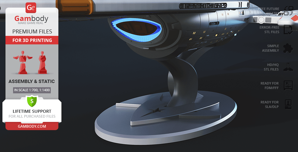
- Features a completely redesigned display stand that presents the starship at an aggressive, cinematic angle (can alternatively still be mounted on landing struts).
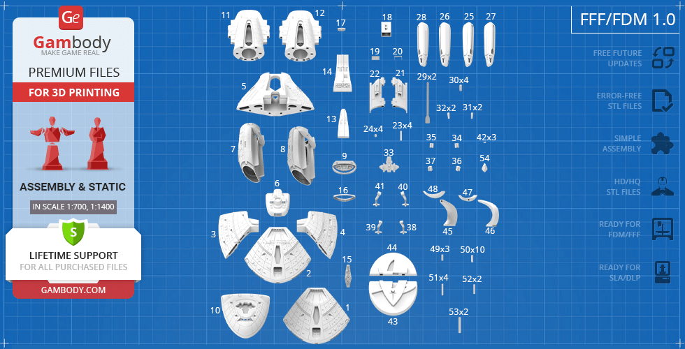
- Some model parts use separate connectors (part "_50_pin_a_X6" requires 6 copies; part "_51_pin_b_X4_FDM" requires 4 copies; part "_52_pin_c_X2_FDM" requires 2 copies).
DLP/SLA
Eco parts
Assembly method
Connectors, Glue
Features
- Retains all versatility from the 1.0 version, including two hull options (smooth or with lettering), open/closed shuttlebay doors with the micro shuttle, an embedded Aeroshuttle, and positional warp nacelles.
- Completely hollowed-out internal hull design for unobstructed, bright LED placement instead of narrow wiring channels.
- Engineered with built-in anti-bleed internal rims along the seams to completely block light leakage between printed parts.
- Phaser arrays are now separated from the main hull segments, vastly improving painting accessibility and enabling clean, precise backlighting edges.
- Features a completely redesigned display stand that presents the starship at an aggressive, cinematic angle (can alternatively still be mounted on landing struts).
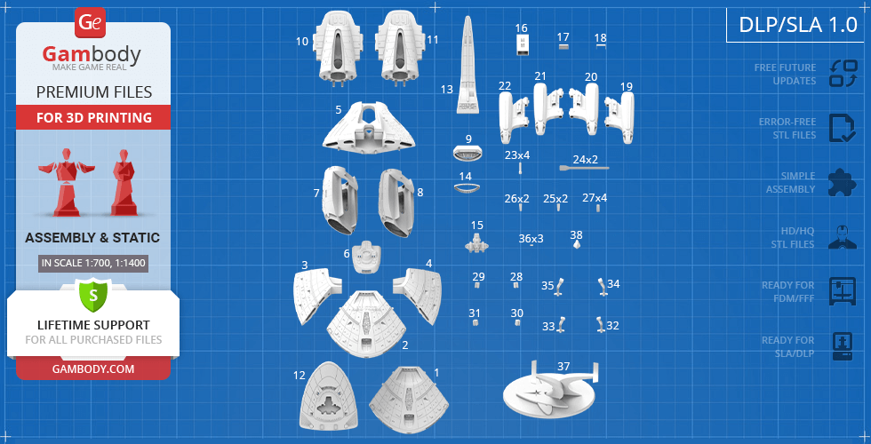
- Some model parts use separate connectors (part "_40_pin_a_X6_SLA" requires 6 copies; part "_41_pin_b_X4_SLA" requires 4 copies; part "_42_pin_c_X2_SLA" requires 2 copies).
FFF/FDM
Assembly method
Connectors, Glue
Features
- Two hull design variants (smooth or with lettering), choice of closed or open shuttlebay doors with a micro shuttle, and an embedded Aeroshuttle.
- Standard horizontal display stand or deployable planetary landing struts.
- Positional nacelle pylons for flat or 30-degree warp-speed display.
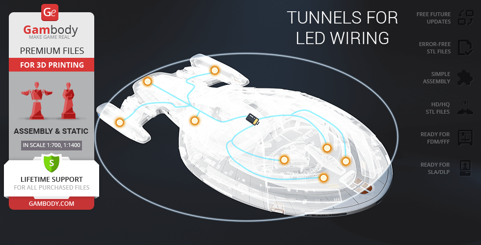
- Built with internal structural tunnels and channels to route custom LED wiring loops through the ship's frame.
- The assembly parts are connected using specially designed integrated connectors that fit securely into the corresponding slots. Optionally, for added strength and rigidity, the static connections can be glued together.
- Some model parts use separate connectors (part "_49_standPin_V1_X3_FDM" requires 3 copies; part "_50_pin_V1_X10_FDM" requires 10 copies; part "_51_pin_V2_X4_FDM" requires 4 copies; part "_52_pin_V3_X2_FDM" requires 2 copies; part "_53_standPin_V2_X2_01_FDM" requires 2 copies).
DLP/SLA
Eco parts
Assembly method
Connectors, Glue
Features
- Two hull design variants (smooth or with lettering), choice of closed or open shuttlebay doors with a micro shuttle, and an embedded Aeroshuttle.
- Standard horizontal display stand or deployable planetary landing struts.
- Positional nacelle pylons for flat or 30-degree warp-speed display.
- Built with internal structural tunnels and channels to route custom LED wiring loops through the ship's frame.
- The assembly parts are connected using specially designed integrated connectors that fit securely into the corresponding slots. Optionally, for added strength and rigidity, the static connections can be glued together.
Additional details
Part of diorama
No
Special pack included
No
You will get instant access to the STL files of USS Voyager 3D Printer Files | Assembly after completing your purchase. Simply add the model to your cart and check out using PayPal, credit or debit card, Apple Pay, Google Pay, Alipay, or other available payment methods.
Watch the assembly video for USS Voyager 3D Printer Files | Assembly, and explore more tutorials, behind-the-scenes content, 3D printing timelapses, and painting guides on the official Gambody YouTube channel.
Before printing, take a look at Printing Details for recommended settings and tips to achieve better results.
| File name | Size (mm | in) | Size(mb) | Printing Time / Filament | |||
|---|---|---|---|---|---|---|
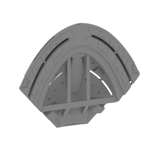 | _01_V1_bodyPart_a_TopF_FDM (repaired).stl 126.6 x 100.81 x 152.52 mm | 4.98 x 3.97 x 6 in | Size: 126.6 x 100.81 x 152.52 mm | 4.98 x 3.97 x 6 in | File size: 17.02 mb | Printing Time / Filament: 29 h 7 min / 16 m | ||
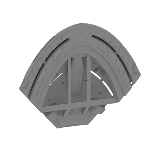 | _01_V2_bodyPart_a_TopF_FDM (repaired).stl 127.01 x 100.29 x 152.51 mm | 5 x 3.95 x 6 in | Size: 127.01 x 100.29 x 152.51 mm | 5 x 3.95 x 6 in | File size: 17.69 mb | Printing Time / Filament: 29 h 2 min / 15 m | ||
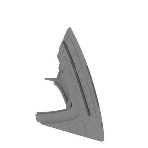 Updated Updated | _02_bodyPart_b_L_FDM (repaired).stlCalculation... | Size:Calculation... | File size: 7.08 mb | Printing Time / Filament: Calculation... | ||
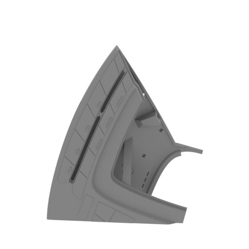 Updated Updated | _03_bodyPart_c_R_FDM (repaired).stlCalculation... | Size:Calculation... | File size: 7.08 mb | Printing Time / Filament: Calculation... | ||
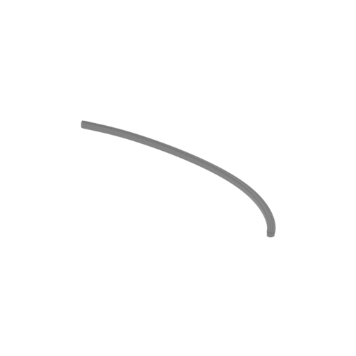 | _04_phazerGlass_a_TopL_FDM (repaired).stl 127.26 x 88.78 x 3.95 mm | 5.01 x 3.5 x 0.16 in | Size: 127.26 x 88.78 x 3.95 mm | 5.01 x 3.5 x 0.16 in | File size: 9.48 mb | Printing Time / Filament: 27 min / <1 m | ||
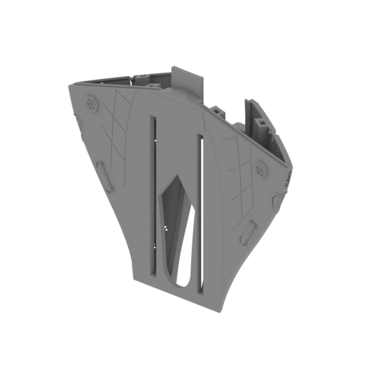 | _05_bodyPart_d_MidT_FDM (repaired).stl 169.67 x 83.96 x 145.56 mm | 6.68 x 3.31 x 5.73 in | Size: 169.67 x 83.96 x 145.56 mm | 6.68 x 3.31 x 5.73 in | File size: 20.73 mb | Printing Time / Filament: 34 h 4 min / 18 m | ||
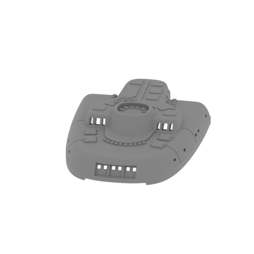 | _06_bodyPart_e_MidT_FDM (repaired).stl 60.79 x 82.77 x 16.55 mm | 2.39 x 3.26 x 0.65 in | Size: 60.79 x 82.77 x 16.55 mm | 2.39 x 3.26 x 0.65 in | File size: 4.74 mb | Printing Time / Filament: 4 h 45 min / 3 m | ||
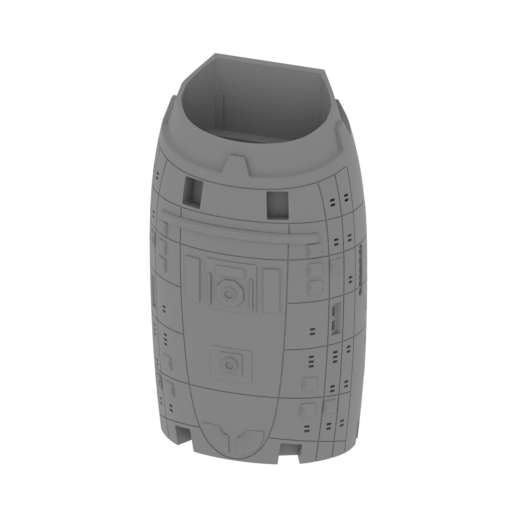 | _07_bodyPartClear_f_Mid_FDM (repaired).stl 81.83 x 57.92 x 144.62 mm | 3.22 x 2.28 x 5.69 in | Size: 81.83 x 57.92 x 144.62 mm | 3.22 x 2.28 x 5.69 in | File size: 11.07 mb | Printing Time / Filament: 26 h 37 min / 15 m | ||
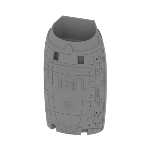 | _08_bodyPartPattern_f_Mid_FDM (repaired).stl 82.47 x 57.97 x 144.63 mm | 3.25 x 2.28 x 5.69 in | Size: 82.47 x 57.97 x 144.63 mm | 3.25 x 2.28 x 5.69 in | File size: 11.61 mb | Printing Time / Filament: 26 h 17 min / 15 m | ||
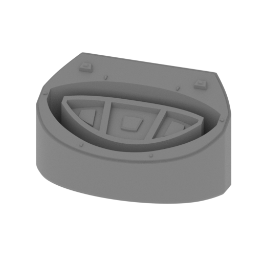 | _09_bodyPart_g_Mid_FDM (repaired).stl 56.73 x 29.77 x 29.94 mm | 2.23 x 1.17 x 1.18 in | Size: 56.73 x 29.77 x 29.94 mm | 2.23 x 1.17 x 1.18 in | File size: 2.54 mb | Printing Time / Filament: 2 h 48 min / 2 m | ||
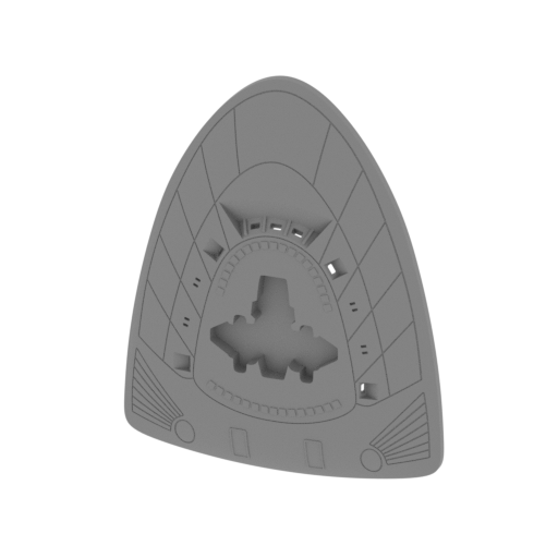 | _10_bodyPart_h_MidBot_FDM (repaired).stl 115.3 x 13.41 x 146.73 mm | 4.54 x 0.53 x 5.78 in | Size: 115.3 x 13.41 x 146.73 mm | 4.54 x 0.53 x 5.78 in | File size: 3.56 mb | Printing Time / Filament: 12 h 25 min / 7 m | ||
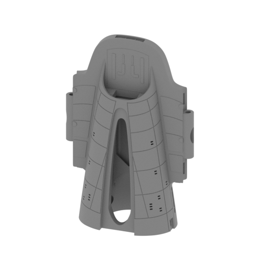 | _11_bodyPartClear_i_Rr_FDM (repaired).stl 99.05 x 50.82 x 145.03 mm | 3.9 x 2 x 5.71 in | Size: 99.05 x 50.82 x 145.03 mm | 3.9 x 2 x 5.71 in | File size: 16.77 mb | Printing Time / Filament: 24 h 14 min / 13 m | ||
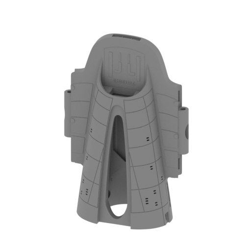 | _12_bodyPartPattern_i_Rr_FDM (repaired).stl 99.05 x 50.82 x 145.03 mm | 3.9 x 2 x 5.71 in | Size: 99.05 x 50.82 x 145.03 mm | 3.9 x 2 x 5.71 in | File size: 16.98 mb | Printing Time / Filament: 24 h 8 min / 13 m | ||
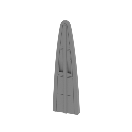 | _13_bodyTopPlanePart_a_FDM (repaired).stl 27.04 x 7.36 x 102.63 mm | 1.06 x 0.29 x 4.04 in | Size: 27.04 x 7.36 x 102.63 mm | 1.06 x 0.29 x 4.04 in | File size: 1.09 mb | Printing Time / Filament: 1 h 35 min / 1 m | ||
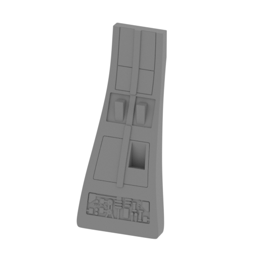 | _14_bodyTopPlanePart_b_FDM (repaired).stl 44.1 x 35.33 x 100.69 mm | 1.74 x 1.39 x 3.96 in | Size: 44.1 x 35.33 x 100.69 mm | 1.74 x 1.39 x 3.96 in | File size: 1.68 mb | Printing Time / Filament: 3 h 10 min / 2 m | ||
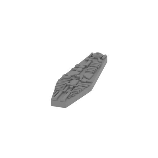 | _15_bodyPartDecor_FrontT_FDM (repaired).stl 15.72 x 53.44 x 4.82 mm | 0.62 x 2.1 x 0.19 in | Size: 15.72 x 53.44 x 4.82 mm | 0.62 x 2.1 x 0.19 in | File size: 1.03 mb | Printing Time / Filament: 28 min / <1 m | ||
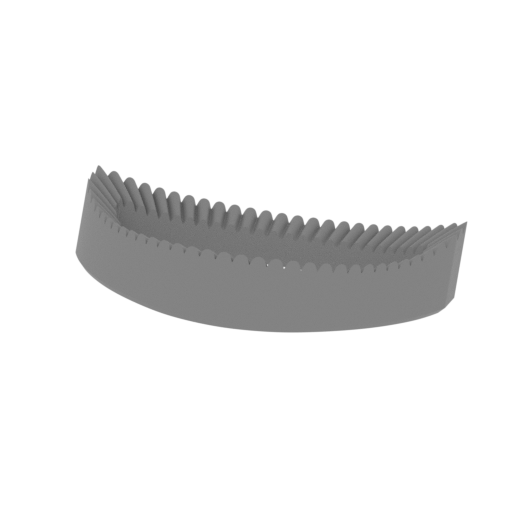 | _16_bodyMidGlassBlue_FDM (repaired).stl 50.81 x 25.72 x 9.25 mm | 2 x 1.01 x 0.36 in | Size: 50.81 x 25.72 x 9.25 mm | 2 x 1.01 x 0.36 in | File size: 1.02 mb | Printing Time / Filament: 44 min / <1 m | ||
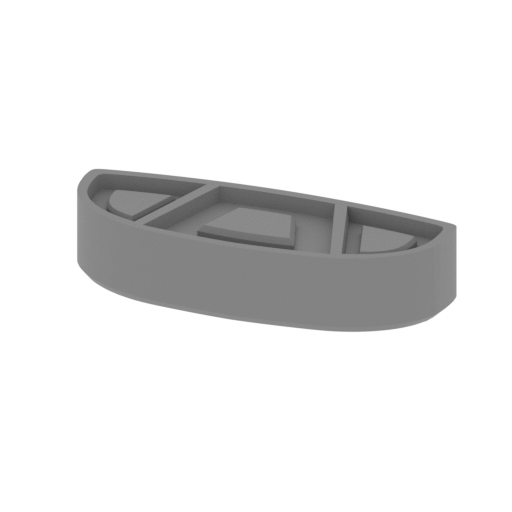 | _17_frontPanel_FDM (repaired).stl 19.06 x 7.1 x 4 mm | 0.75 x 0.28 x 0.16 in | Size: 19.06 x 7.1 x 4 mm | 0.75 x 0.28 x 0.16 in | File size: 0.11 mb | Printing Time / Filament: 6 min / <1 m | ||
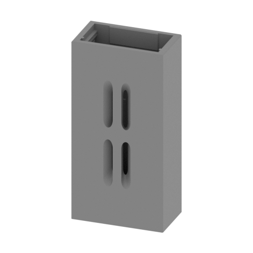 | _18_tailHangarInner_FDM (repaired).stl 23.38 x 13.11 x 46.47 mm | 0.92 x 0.52 x 1.83 in | Size: 23.38 x 13.11 x 46.47 mm | 0.92 x 0.52 x 1.83 in | File size: 0.38 mb | Printing Time / Filament: 1 h 46 min / 1 m | ||
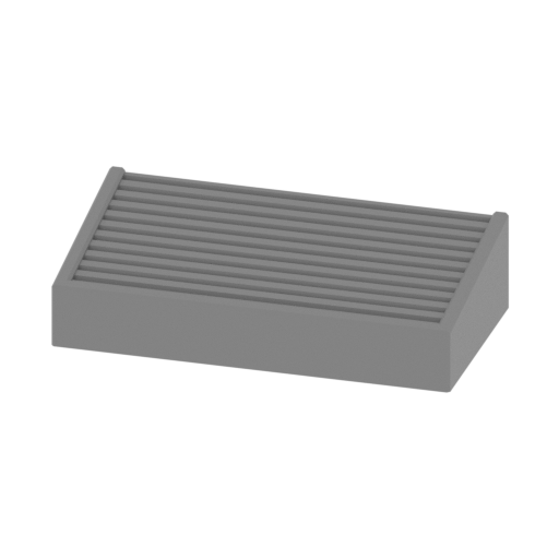 | _19_tailDoorClose_FDM (repaired).stl 18.74 x 10.71 x 4.55 mm | 0.74 x 0.42 x 0.18 in | Size: 18.74 x 10.71 x 4.55 mm | 0.74 x 0.42 x 0.18 in | File size: 0.05 mb | Printing Time / Filament: 8 min / <1 m | ||
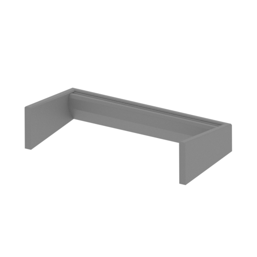 | _20_tailDoorOpen_FDM (repaired).stl 19.34 x 12.14 x 4.63 mm | 0.76 x 0.48 x 0.18 in | Size: 19.34 x 12.14 x 4.63 mm | 0.76 x 0.48 x 0.18 in | File size: 0.02 mb | Printing Time / Filament: 4 min / <1 m | ||
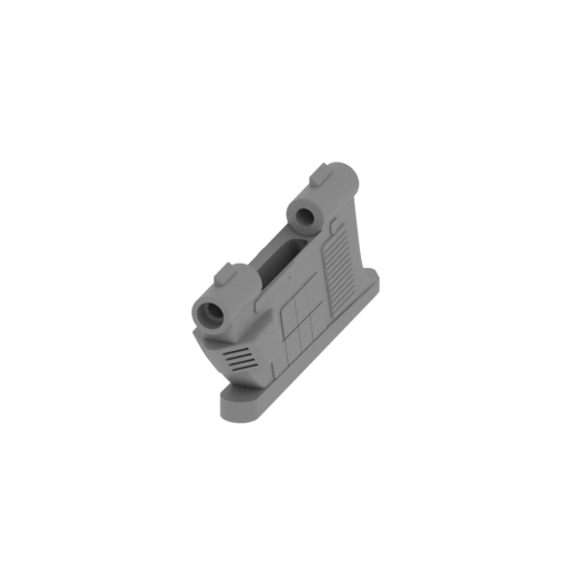 Updated Updated | _21_enginePilon_a_L_FDM (repaired).stlCalculation... | Size:Calculation... | File size: 3.24 mb | Printing Time / Filament: Calculation... | ||
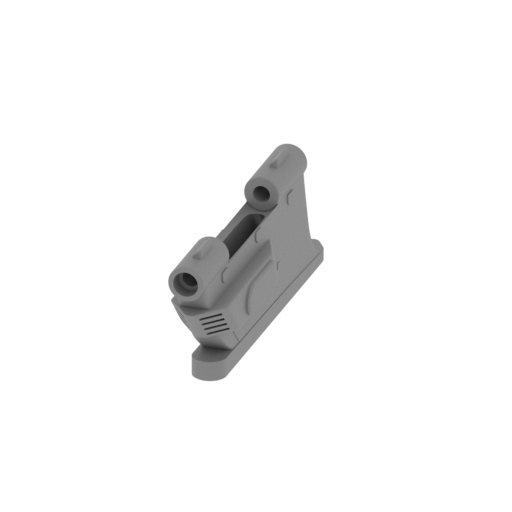 Updated Updated | _22_enginePilon_b_R_FDM (repaired).stlCalculation... | Size:Calculation... | File size: 3.24 mb | Printing Time / Filament: Calculation... | ||
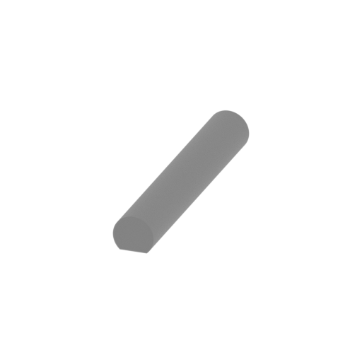 | _23_enginePilonAxis_X4_FDM (repaired).stl 4 x 25.7 x 3.5 mm | 0.16 x 1.01 x 0.14 in | Size: 4 x 25.7 x 3.5 mm | 0.16 x 1.01 x 0.14 in | File size: 0.24 mb | Printing Time / Filament: 5 min / <1 m | ||
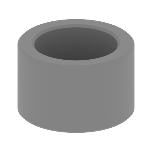 | _24_enginePilonAxisCap_X4_FDM (repaired).stl 6 x 6 x 3.8 mm | 0.24 x 0.24 x 0.15 in | Size: 6 x 6 x 3.8 mm | 0.24 x 0.24 x 0.15 in | File size: 0.18 mb | Printing Time / Filament: 3 min / <1 m | ||
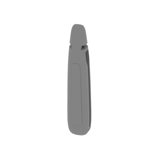 | _25_engineBodyClear_a_L_FDM (repaired).stl 26.58 x 24.15 x 139.7 mm | 1.05 x 0.95 x 5.5 in | Size: 26.58 x 24.15 x 139.7 mm | 1.05 x 0.95 x 5.5 in | File size: 11.80 mb | Printing Time / Filament: 6 h 3 min / 3 m | ||
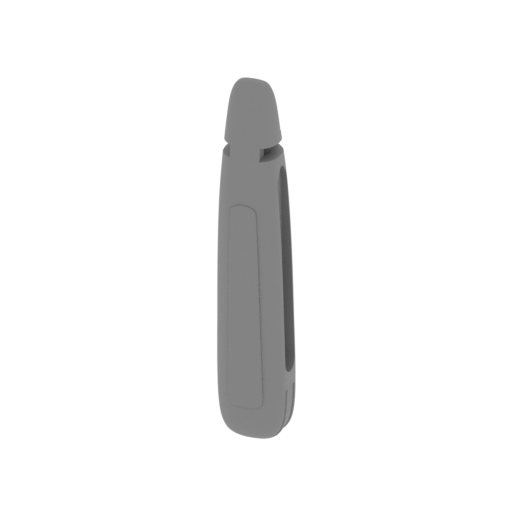 | _26_engineBodyClear_b_R_FDM (repaired).stl 26.65 x 24.27 x 139.7 mm | 1.05 x 0.96 x 5.5 in | Size: 26.65 x 24.27 x 139.7 mm | 1.05 x 0.96 x 5.5 in | File size: 11.80 mb | Printing Time / Filament: 5 h 57 min / 3 m | ||
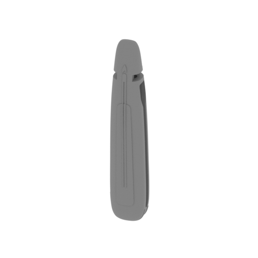 | _27_engineBodyPattern_a_L_FDM (repaired).stl 26.58 x 24.93 x 139.7 mm | 1.05 x 0.98 x 5.5 in | Size: 26.58 x 24.93 x 139.7 mm | 1.05 x 0.98 x 5.5 in | File size: 12.39 mb | Printing Time / Filament: 6 h 11 min / 3 m | ||
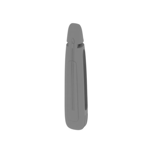 | _28_engineBodyPattern_b_R_FDM (repaired).stl 26.57 x 25.08 x 139.7 mm | 1.05 x 0.99 x 5.5 in | Size: 26.57 x 25.08 x 139.7 mm | 1.05 x 0.99 x 5.5 in | File size: 12.39 mb | Printing Time / Filament: 6 h 2 min / 3 m | ||
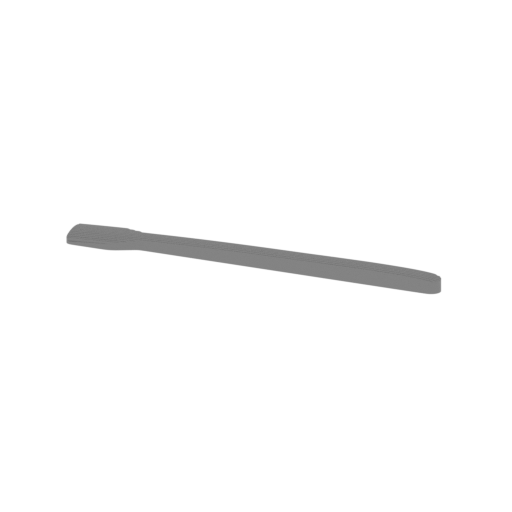 | _29_engineGlassBlue_X2_FDM (repaired).stl 97.96 x 10.28 x 4.19 mm | 3.86 x 0.4 x 0.16 in | Size: 97.96 x 10.28 x 4.19 mm | 3.86 x 0.4 x 0.16 in | File size: 3.23 mb | Printing Time / Filament: 22 min / <1 m | ||
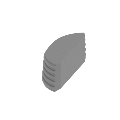 | _30_enginePartYellow_X4_FDM (repaired).stl 4.66 x 15.8 x 4.96 mm | 0.18 x 0.62 x 0.2 in | Size: 4.66 x 15.8 x 4.96 mm | 0.18 x 0.62 x 0.2 in | File size: 1.78 mb | Printing Time / Filament: 5 min / <1 m | ||
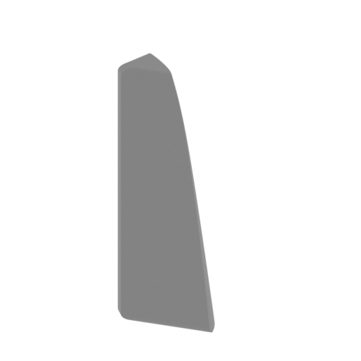 | _31_engineGlassRed_a_X2_FDM (repaired).stl 5.44 x 5.7 x 14.74 mm | 0.21 x 0.22 x 0.58 in | Size: 5.44 x 5.7 x 14.74 mm | 0.21 x 0.22 x 0.58 in | File size: 0.29 mb | Printing Time / Filament: 5 min / <1 m | ||
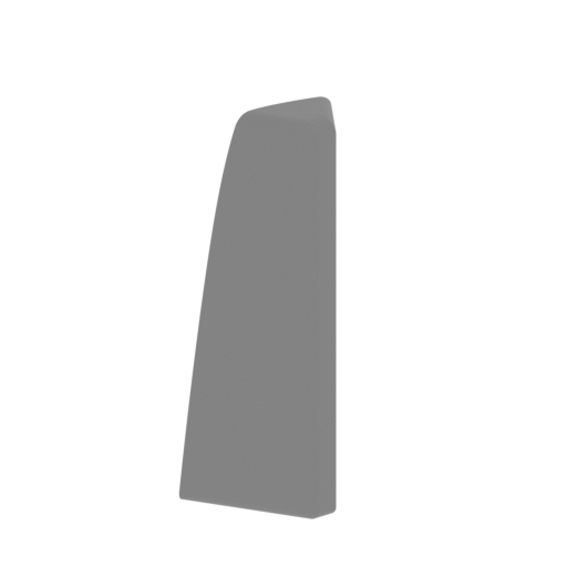 | _32_engineGlassRed_b_X2_FDM (repaired).stl 5.44 x 5.7 x 14.74 mm | 0.21 x 0.22 x 0.58 in | Size: 5.44 x 5.7 x 14.74 mm | 0.21 x 0.22 x 0.58 in | File size: 0.29 mb | Printing Time / Filament: 5 min / <1 m | ||
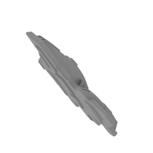 Updated Updated | _33_aeroShattle_FDM (repaired).stl 46.6 x 21.8 x 32 mm | 1.83 x 0.86 x 1.26 in | Size: 46.6 x 21.8 x 32 mm | 1.83 x 0.86 x 1.26 in | File size: 14.52 mb | Printing Time / Filament: 26 min / 1 m Slicer: prusa v2.9.2 Printer: prusa_xl Non default settings Layer height: 0.2 Fill density: 20% Support material: 1 Support material buildplate only: 1 | ||
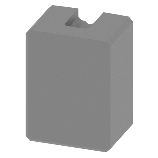 | _34_landingGearDoorClose_FrontL_FDM (repaired).stl 7.83 x 6.11 x 10.51 mm | 0.31 x 0.24 x 0.41 in | Size: 7.83 x 6.11 x 10.51 mm | 0.31 x 0.24 x 0.41 in | File size: 0.04 mb | Printing Time / Filament: 10 min / <1 m | ||
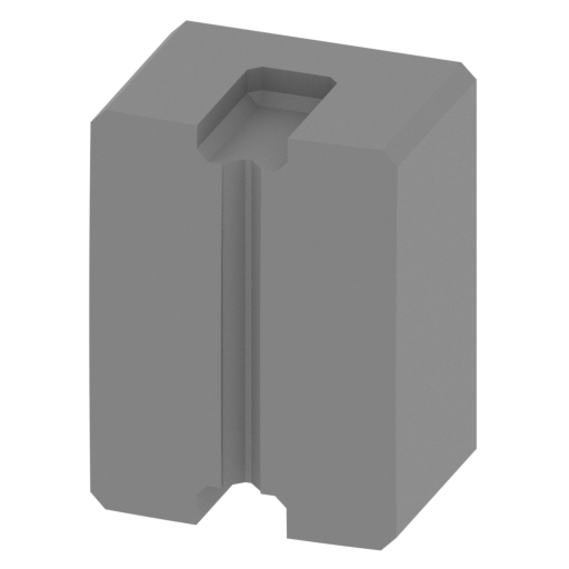 | _35_landingGearDoorClose_FrontR_FDM (repaired).stl 7.83 x 6.11 x 10.51 mm | 0.31 x 0.24 x 0.41 in | Size: 7.83 x 6.11 x 10.51 mm | 0.31 x 0.24 x 0.41 in | File size: 0.04 mb | Printing Time / Filament: 10 min / <1 m | ||
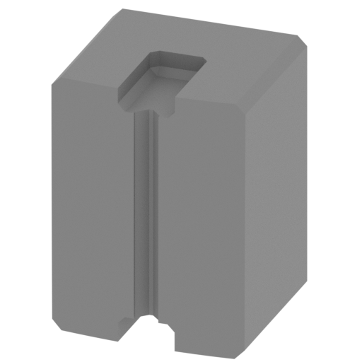 | _36_landingGearDoorClose_RearL_FDM (repaired).stl 7.83 x 7.64 x 10.51 mm | 0.31 x 0.3 x 0.41 in | Size: 7.83 x 7.64 x 10.51 mm | 0.31 x 0.3 x 0.41 in | File size: 0.03 mb | Printing Time / Filament: 10 min / <1 m | ||
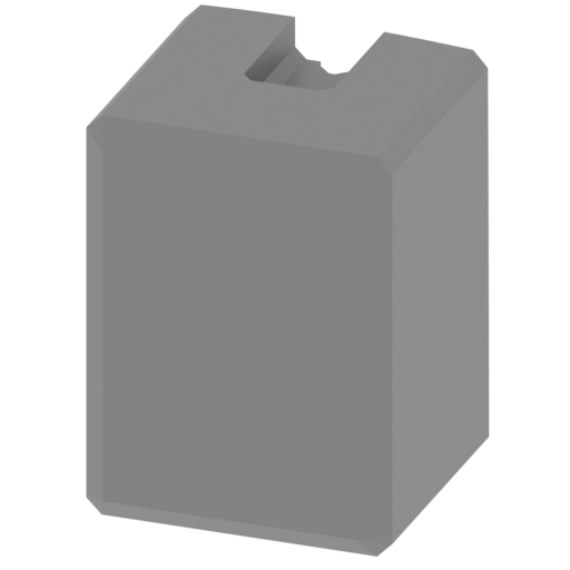 | _37_landingGearDoorClose_RearR_FDM (repaired).stl 7.83 x 7.64 x 10.51 mm | 0.31 x 0.3 x 0.41 in | Size: 7.83 x 7.64 x 10.51 mm | 0.31 x 0.3 x 0.41 in | File size: 0.03 mb | Printing Time / Filament: 10 min / <1 m | ||
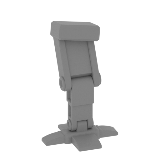 | _38_landinGlear_FrontL_FDM (repaired).stl 17.36 x 18.06 x 30.43 mm | 0.68 x 0.71 x 1.2 in | Size: 17.36 x 18.06 x 30.43 mm | 0.68 x 0.71 x 1.2 in | File size: 1.04 mb | Printing Time / Filament: 36 min / <1 m | ||
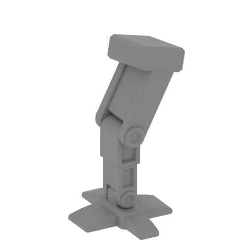 | _39_landinGlear_FrontLR_FDM (repaired).stl 17.44 x 18.06 x 30.43 mm | 0.69 x 0.71 x 1.2 in | Size: 17.44 x 18.06 x 30.43 mm | 0.69 x 0.71 x 1.2 in | File size: 1.06 mb | Printing Time / Filament: 36 min / <1 m | ||
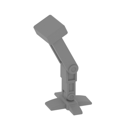 | _40_landinGlear_RearL_FDM (repaired).stl 19.22 x 19.16 x 33.61 mm | 0.76 x 0.75 x 1.32 in | Size: 19.22 x 19.16 x 33.61 mm | 0.76 x 0.75 x 1.32 in | File size: 1.04 mb | Printing Time / Filament: 40 min / <1 m | ||
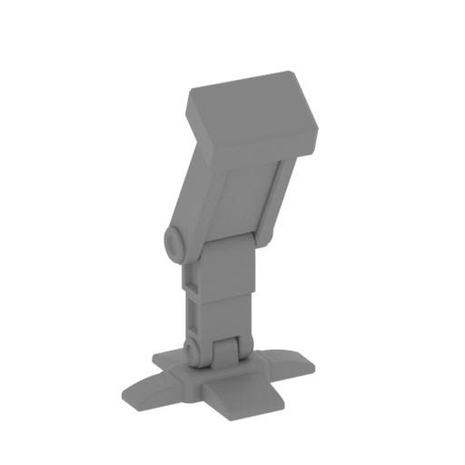 | _41_landinGlear_RearR_FDM (repaired).stl 19.28 x 19.13 x 33.6 mm | 0.76 x 0.75 x 1.32 in | Size: 19.28 x 19.13 x 33.6 mm | 0.76 x 0.75 x 1.32 in | File size: 1.03 mb | Printing Time / Filament: 40 min / <1 m | ||
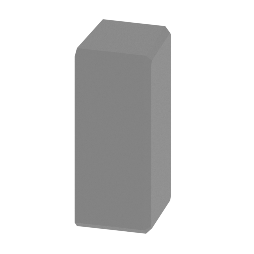 | _42_tailBodyPartGlass_X3_FDM (repaired).stl 2.31 x 2.8 x 5.88 mm | 0.09 x 0.11 x 0.23 in | Size: 2.31 x 2.8 x 5.88 mm | 0.09 x 0.11 x 0.23 in | File size: 0.01 mb | Printing Time / Filament: 2 min / <1 m | ||
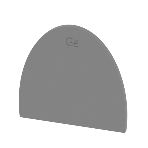 | _43_standPart_a_FDM (repaired).stl 114.37 x 10.6 x 108.01 mm | 4.5 x 0.42 x 4.25 in | Size: 114.37 x 10.6 x 108.01 mm | 4.5 x 0.42 x 4.25 in | File size: 0.40 mb | Printing Time / Filament: 9 h 4 min / 5 m | ||
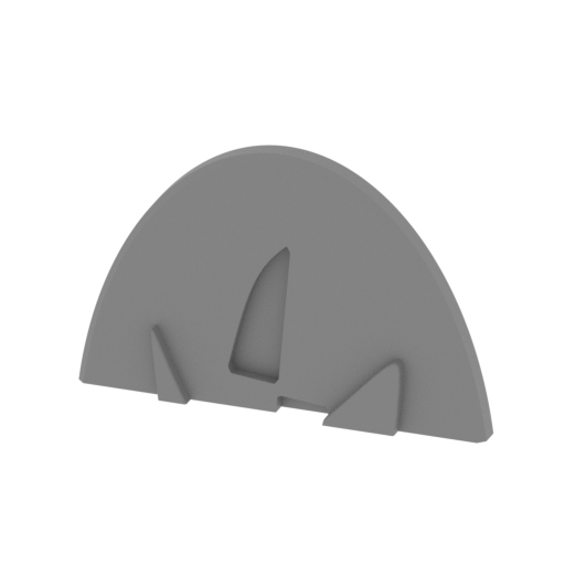 | _44_standPart_b_FDM (repaired).stl 112.1 x 10.6 x 72.35 mm | 4.41 x 0.42 x 2.85 in | Size: 112.1 x 10.6 x 72.35 mm | 4.41 x 0.42 x 2.85 in | File size: 0.47 mb | Printing Time / Filament: 4 h 56 min / 3 m | ||
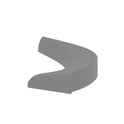 | _45_standPart_c_FDM (repaired).stl 53.13 x 64.74 x 14.64 mm | 2.09 x 2.55 x 0.58 in | Size: 53.13 x 64.74 x 14.64 mm | 2.09 x 2.55 x 0.58 in | File size: 3.42 mb | Printing Time / Filament: 1 h 50 min / 1 m | ||
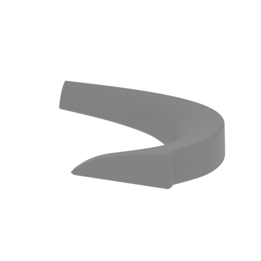 | _46_standPart_d_FDM (repaired).stl 73.59 x 59.35 x 14.42 mm | 2.9 x 2.34 x 0.57 in | Size: 73.59 x 59.35 x 14.42 mm | 2.9 x 2.34 x 0.57 in | File size: 4.13 mb | Printing Time / Filament: 2 h 2 min / 1 m | ||
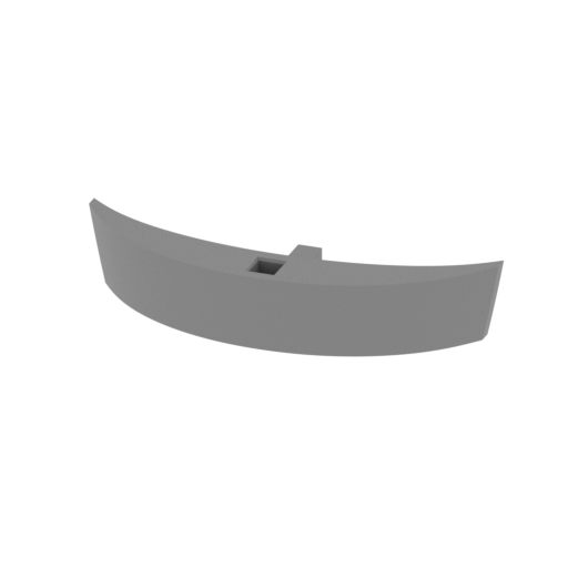 | _47_standPart_e_FDM (repaired).stl 52.17 x 19.86 x 10 mm | 2.05 x 0.78 x 0.39 in | Size: 52.17 x 19.86 x 10 mm | 2.05 x 0.78 x 0.39 in | File size: 0.20 mb | Printing Time / Filament: 29 min / <1 m | ||
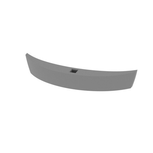 | _48_standPart_f_FDM (repaired).stl 61.36 x 17.3 x 10 mm | 2.42 x 0.68 x 0.39 in | Size: 61.36 x 17.3 x 10 mm | 2.42 x 0.68 x 0.39 in | File size: 0.36 mb | Printing Time / Filament: 32 min / <1 m | ||
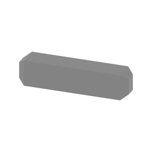 | _49_standPin_a_X3_FDM (repaired).stl 15 x 3 x 3.53 mm | 0.59 x 0.12 x 0.14 in | Size: 15 x 3 x 3.53 mm | 0.59 x 0.12 x 0.14 in | File size: 0.00 mb | Printing Time / Filament: 4 min / <1 m | ||
 | _50_pin_a_X6 (repaired).stl 17.48 x 3.53 x 3 mm | 0.69 x 0.14 x 0.12 in | Size: 17.48 x 3.53 x 3 mm | 0.69 x 0.14 x 0.12 in | File size: 0.00 mb | Printing Time / Filament: 4 min / <1 m | ||
 | _51_pin_b_X4_FDM (repaired).stl 3 x 28.07 x 4 mm | 0.12 x 1.11 x 0.16 in | Size: 3 x 28.07 x 4 mm | 0.12 x 1.11 x 0.16 in | File size: 0.00 mb | Printing Time / Filament: 5 min / <1 m | ||
 | _52_pin_c_X2_FDM (repaired).stl 3 x 22.89 x 4 mm | 0.12 x 0.9 x 0.16 in | Size: 3 x 22.89 x 4 mm | 0.12 x 0.9 x 0.16 in | File size: 0.00 mb | Printing Time / Filament: 5 min / <1 m | ||
 | _53_standPin_b_X2_FDM (repaired).stl 3.53 x 37.77 x 5.74 mm | 0.14 x 1.49 x 0.23 in | Size: 3.53 x 37.77 x 5.74 mm | 0.14 x 1.49 x 0.23 in | File size: 0.00 mb | Printing Time / Filament: 9 min / <1 m | ||
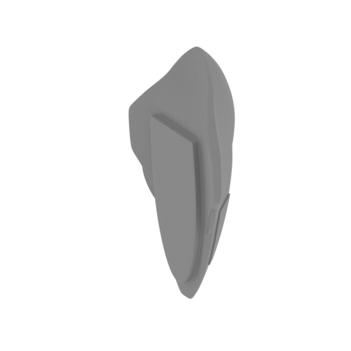 | _54_deltaFlyerMini_FDM (repaired).stl 11.29 x 9.28 x 22.89 mm | 0.44 x 0.37 x 0.9 in | Size: 11.29 x 9.28 x 22.89 mm | 0.44 x 0.37 x 0.9 in | File size: 3.52 mb | Printing Time / Filament: 11 min / <1 m | ||
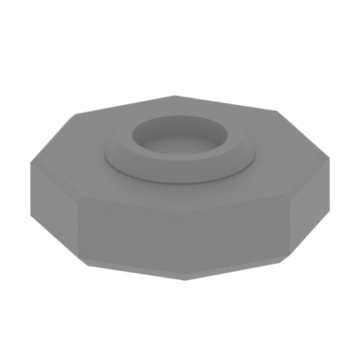 | _55_bodyStandPinCap_FDM (repaired).stl 10.32 x 10.33 x 3.67 mm | 0.41 x 0.41 x 0.14 in | Size: 10.32 x 10.33 x 3.67 mm | 0.41 x 0.41 x 0.14 in | File size: 0.08 mb | Printing Time / Filament: 4 min / <1 m | ||
 | _56_phazerGlass_b_TopR_FDM (repaired).stl 37.47 x 151.68 x 3.59 mm | 1.48 x 5.97 x 0.14 in | Size: 37.47 x 151.68 x 3.59 mm | 1.48 x 5.97 x 0.14 in | File size: 3.39 mb | Printing Time / Filament: 23 min / <1 m | ||
 | _57_phazerGlass_c_BotL_FDM (repaired).stl 25.83 x 184.47 x 2.81 mm | 1.02 x 7.26 x 0.11 in | Size: 25.83 x 184.47 x 2.81 mm | 1.02 x 7.26 x 0.11 in | File size: 6.89 mb | Printing Time / Filament: 30 min / <1 m | ||
 | _58_phazerGlass_d_BotR_FDM (repaired).stl 25.83 x 184.47 x 2.91 mm | 1.02 x 7.26 x 0.11 in | Size: 25.83 x 184.47 x 2.91 mm | 1.02 x 7.26 x 0.11 in | File size: 6.89 mb | Printing Time / Filament: 31 min / <1 m | ||
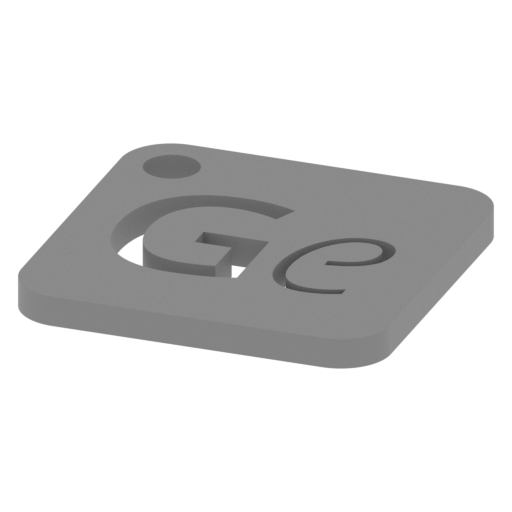 | Keychain (repaired).stl 29.68 x 29.69 x 2.42 mm | 1.17 x 1.17 x 0.1 in | Size: 29.68 x 29.69 x 2.42 mm | 1.17 x 1.17 x 0.1 in | File size: 0.37 mb | Printing Time / Filament: 23 min / <1 m | ||
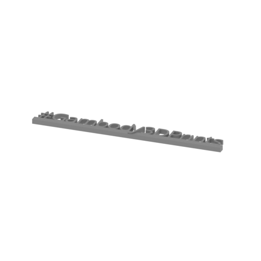 | Tag (repaired).stl 150.15 x 18.16 x 4.59 mm | 5.91 x 0.71 x 0.18 in | Size: 150.15 x 18.16 x 4.59 mm | 5.91 x 0.71 x 0.18 in | File size: 1.78 mb | Printing Time / Filament: 1 h 18 min / 1 m | ||
 | _59_enginePilonCap_X2_FDM (repaired).stlCalculation... | Size:Calculation... | File size: 0.13 mb | Printing Time / Filament: Calculation... | ||
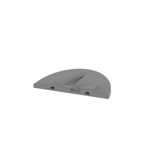 | _44_V2_standPart_b_FDM (repaired).stl 112.1 x 72.4 x 10.6 mm | 4.41 x 2.85 x 0.42 in | Size: 112.1 x 72.4 x 10.6 mm | 4.41 x 2.85 x 0.42 in | File size: 0.51 mb | Printing Time / Filament: 40 min / 7 m Slicer: prusa v2.9.2 Printer: prusa_xl Non default settings Layer height: 0.2 Fill density: 20% Support material: 1 Support material buildplate only: 1 | ||
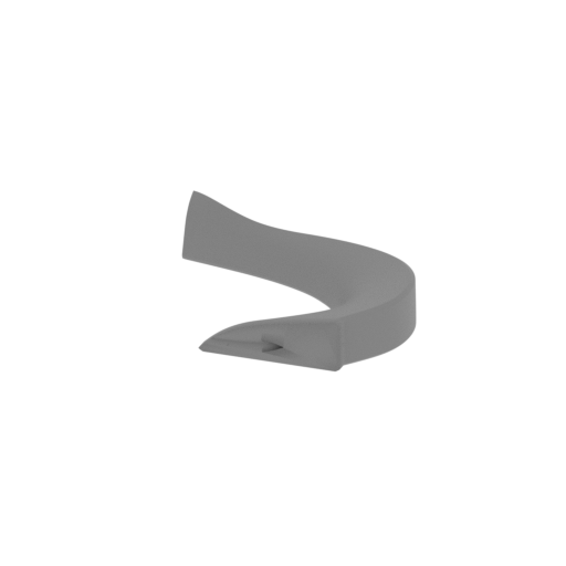 | _46_V2_standPart_d_FDM (repaired).stl 73.6 x 59.8 x 17.7 mm | 2.9 x 2.35 x 0.7 in | Size: 73.6 x 59.8 x 17.7 mm | 2.9 x 2.35 x 0.7 in | File size: 4.24 mb | Printing Time / Filament: 28 min / 4 m Slicer: prusa v2.9.2 Printer: prusa_xl Non default settings Layer height: 0.2 Fill density: 20% Support material: 1 Support material buildplate only: 1 | ||
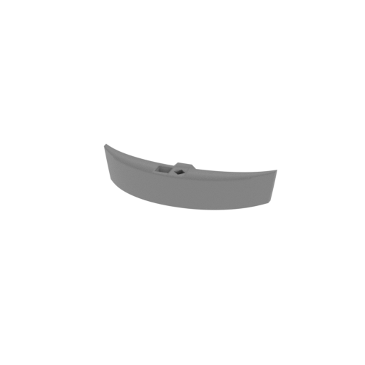 | _47_V2_standPart_e_FDM (repaired).stl 52.2 x 15.1 x 10.2 mm | 2.06 x 0.59 x 0.4 in | Size: 52.2 x 15.1 x 10.2 mm | 2.06 x 0.59 x 0.4 in | File size: 0.21 mb | Printing Time / Filament: 10 min / 1 m Slicer: prusa v2.9.2 Printer: prusa_xl Non default settings Layer height: 0.2 Fill density: 20% Support material: 1 Support material buildplate only: 1 | ||
3D model history
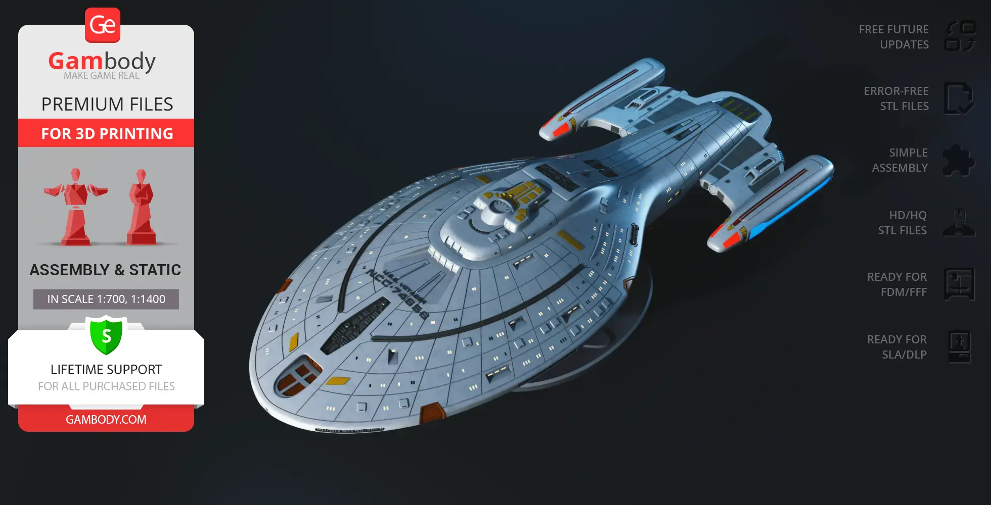
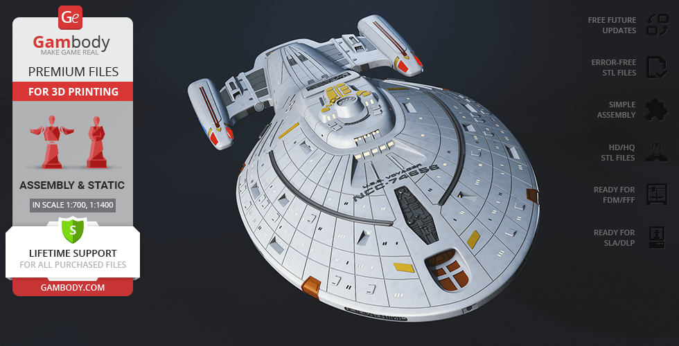
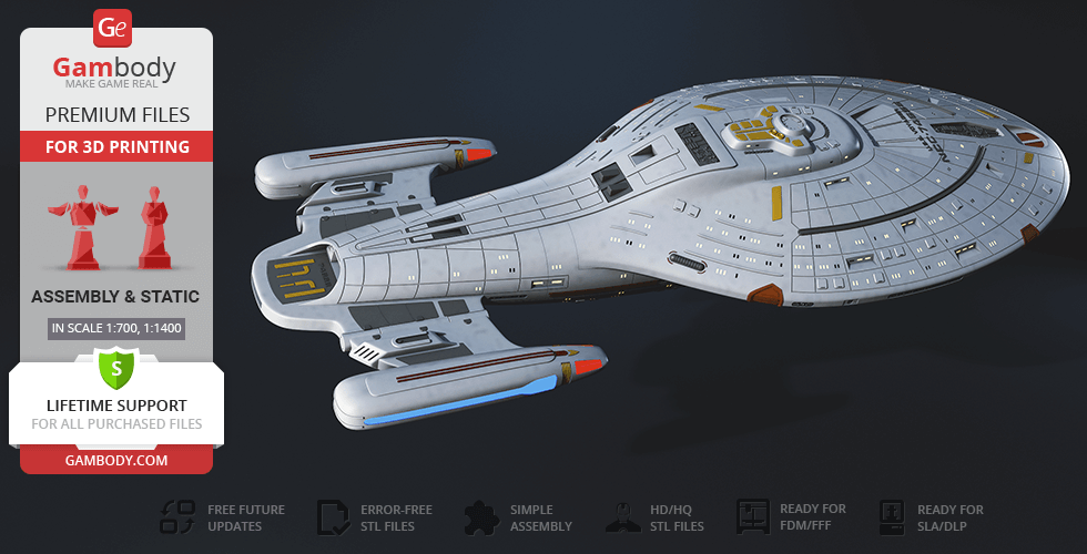
Voyager rarely feels like just another Starfleet vessel. Stranded seventy thousand light-years from home with a combined Starfleet and Maquis crew, it was a ship forced to become a self-sustaining sanctuary in the uncharted Delta Quadrant. Operating at the technological peak of the mid-24th-century Star Trek universe, this Intrepid-class starship traded massive scale for compact agility, integrating bio-neural gel packs and a warp drive engineered to hit a blistering warp 9.975. Over a perilous seven-year odyssey, the ship survived through pure field improvisation, famously absorbing salvaged Borg tech into its hull. For collectors of sci-fi 3D models, Voyager represents the ultimate story of endurance, proving that a ship becomes a true home when the crew refuses to let their ideals drift in the dark.
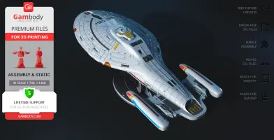
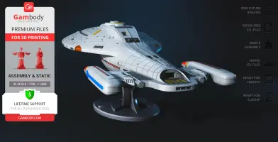
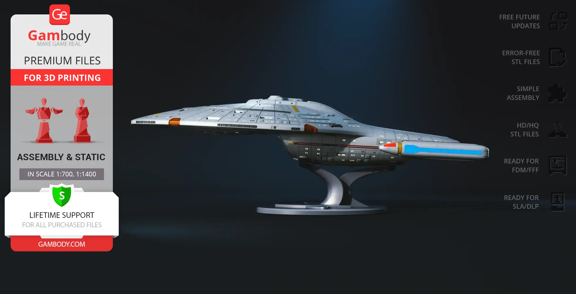
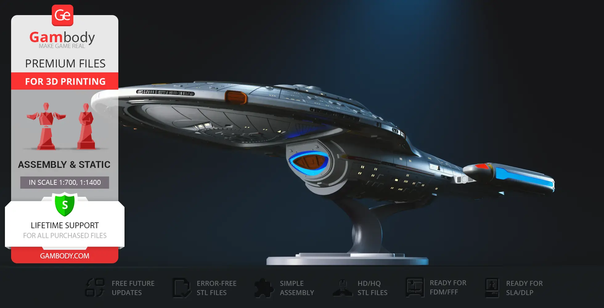
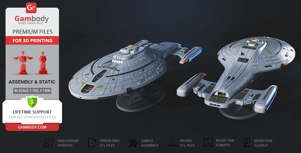
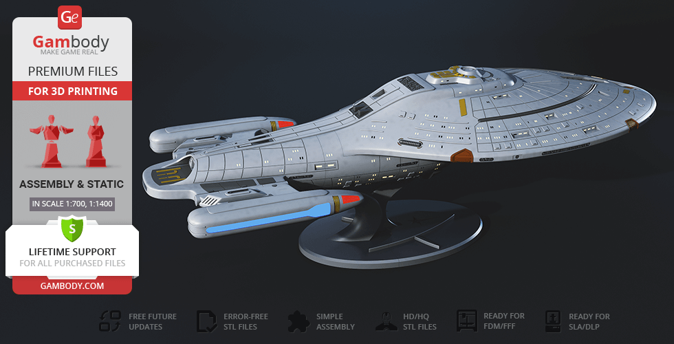
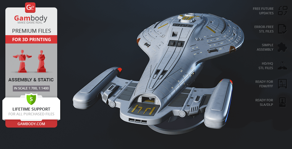
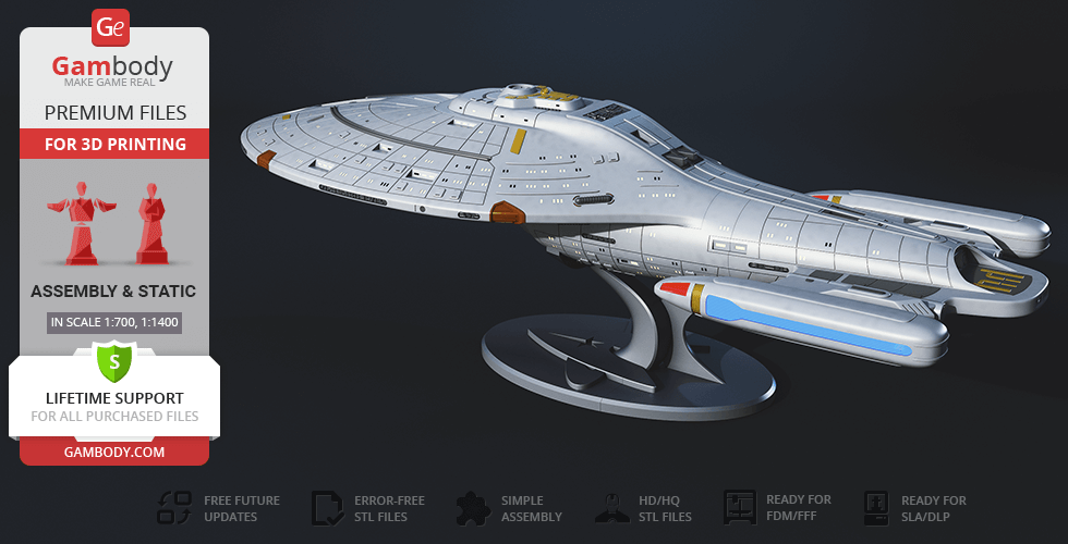
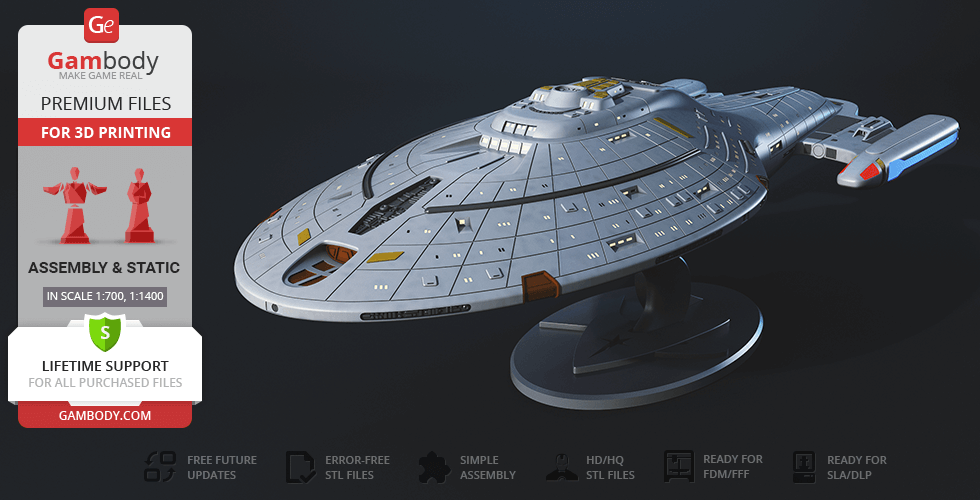
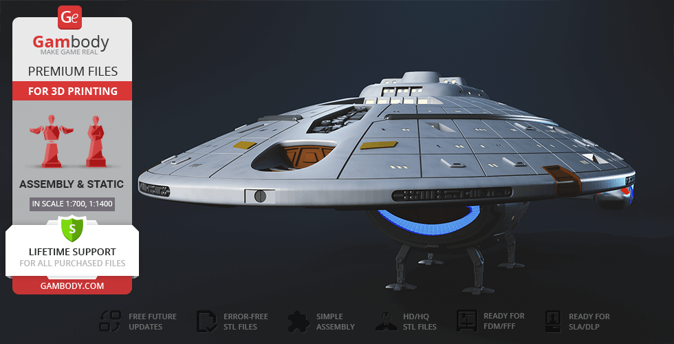
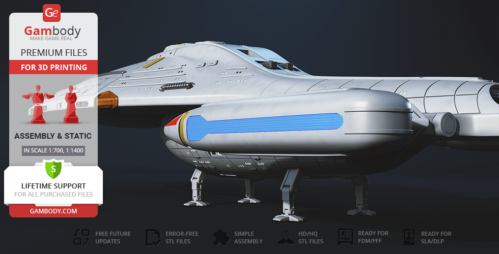
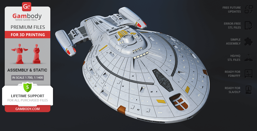
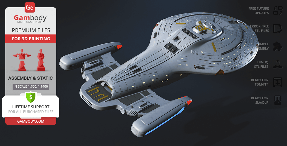
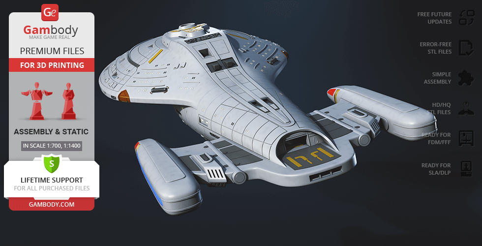
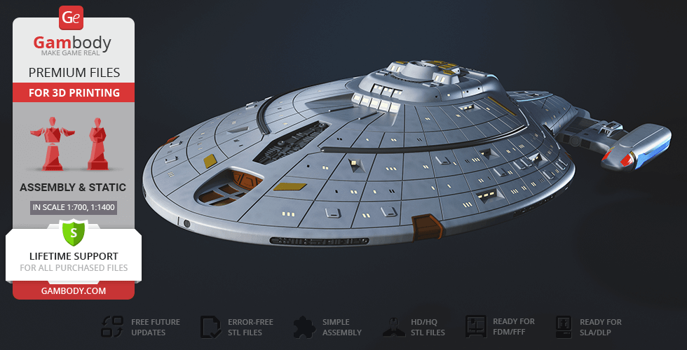
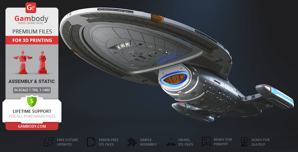
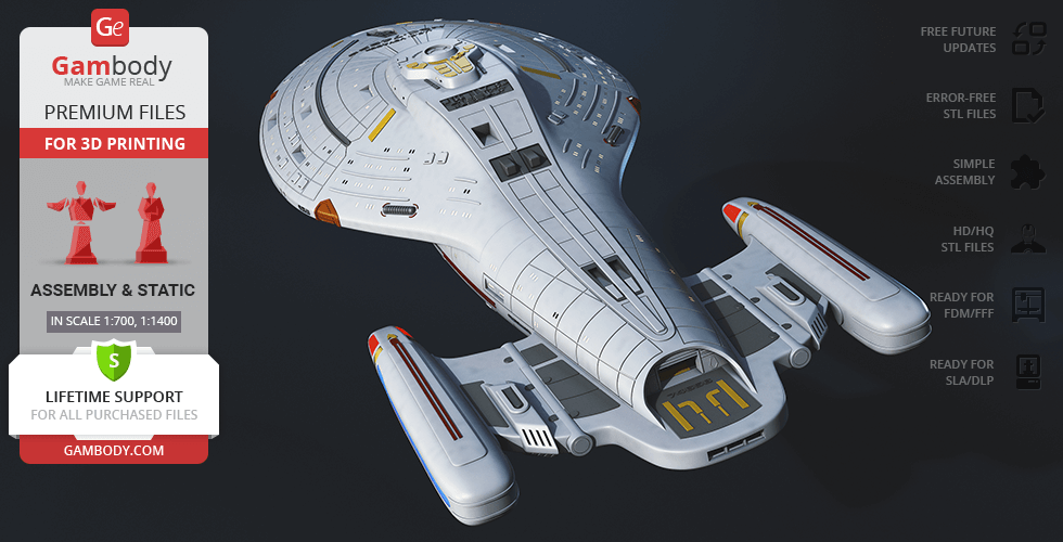
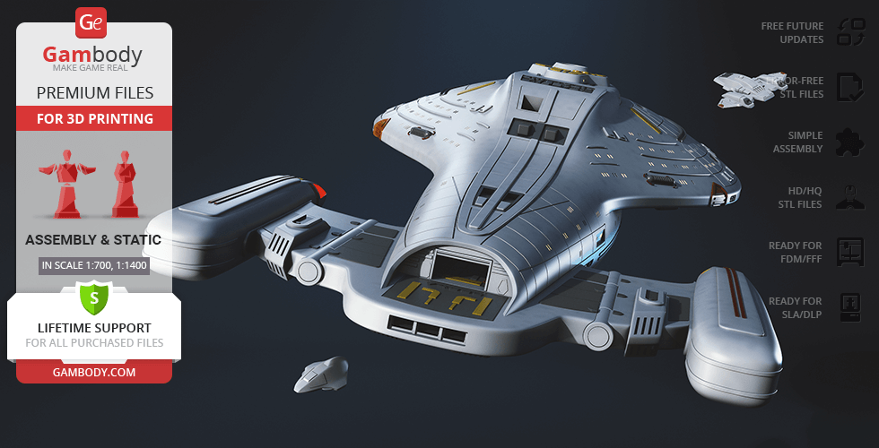
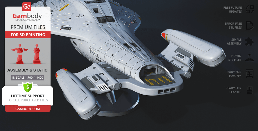
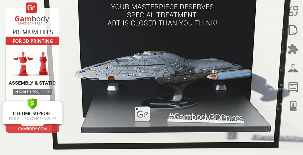
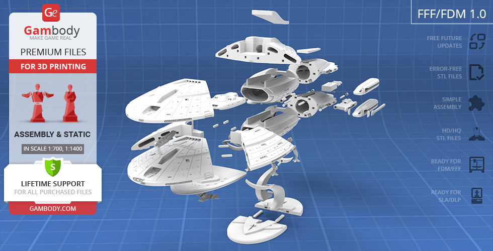
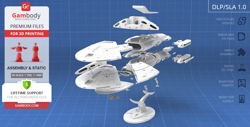
This premium starship 3D print model translates that legendary silhouette into a sophisticated assembly project for your workbench. The meticulously engineered hull can be displayed either on a sleek presentation stand at a dynamic angle or touching down directly on its advanced planetary landing gear. True to the functional mechanics seen in the TV series franchise, the design features movable warp nacelles that pivot up to a thirty-degree angle, an embedded Aeroshuttle, and an interchangeable shuttlebay complete with a tiny micro shuttle. This spaceship STL is fully optimised for custom LED wiring and includes a version with completely hollowed-out internal compartments and integrated anti-bleed light rims. Combined with separate phaser array segments for easy painting, this movie 3D model project is the definitive spacecraft 3D model release for builders looking to download a premium USS Voyager 3D model.
3D printing model features
Model-specific features:
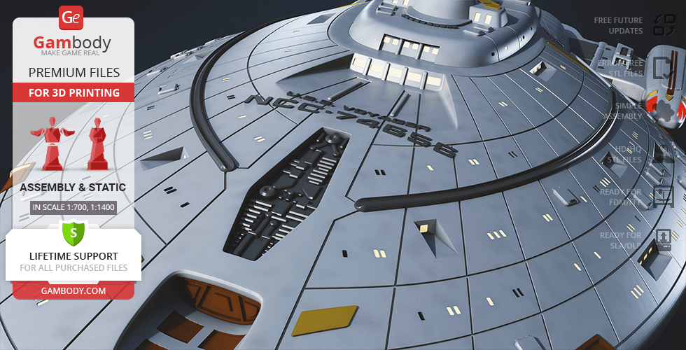
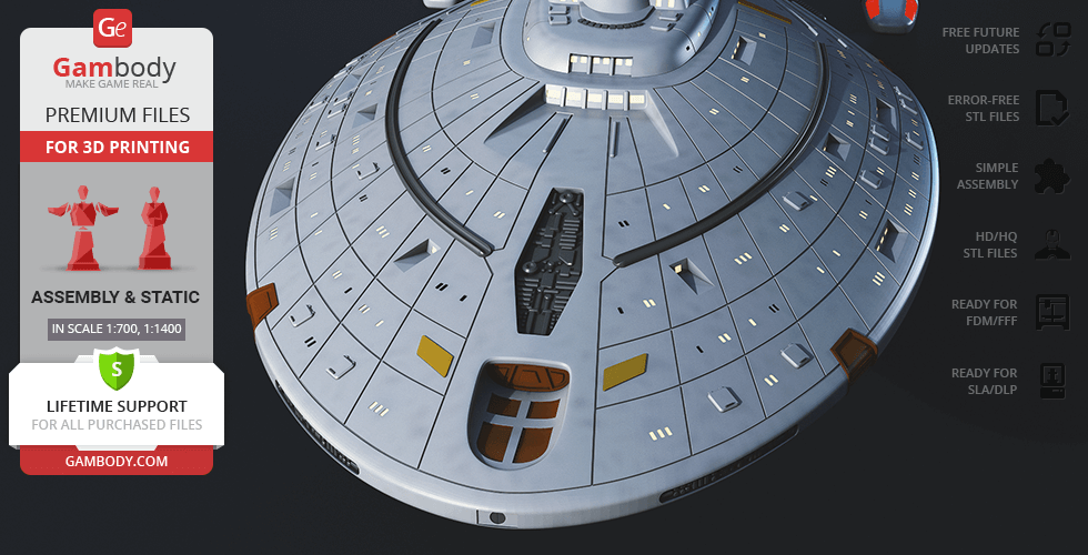
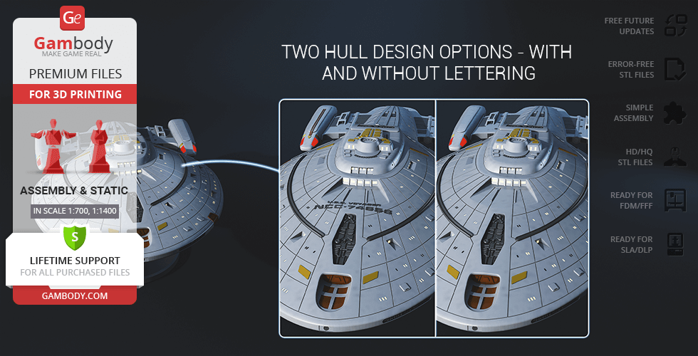
- Features two distinct hull options, including one variant with embossed Starfleet registry markings and a clean, smooth alternative.
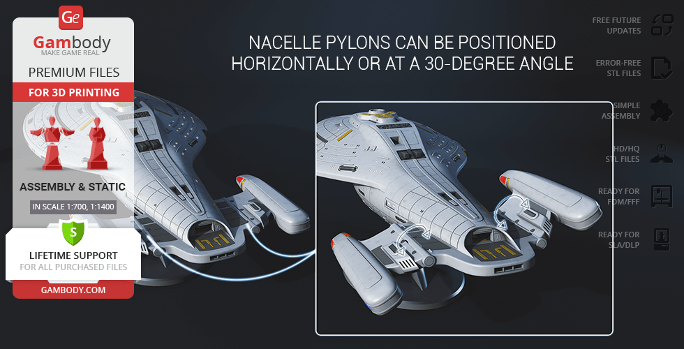
- Engineered with variable-geometry warp nacelles that can be positioned horizontally or tilted at a screen-accurate 30-degree angle.
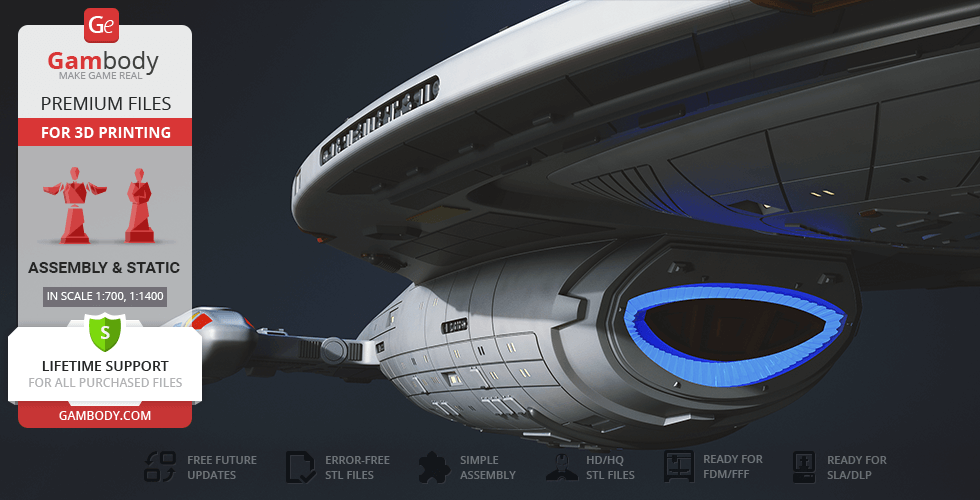
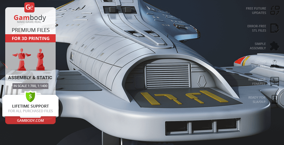
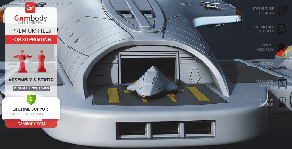
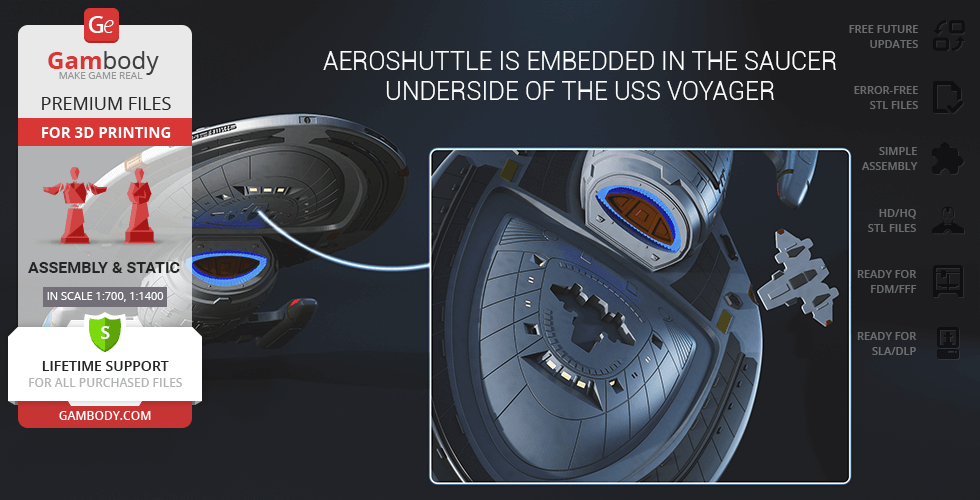
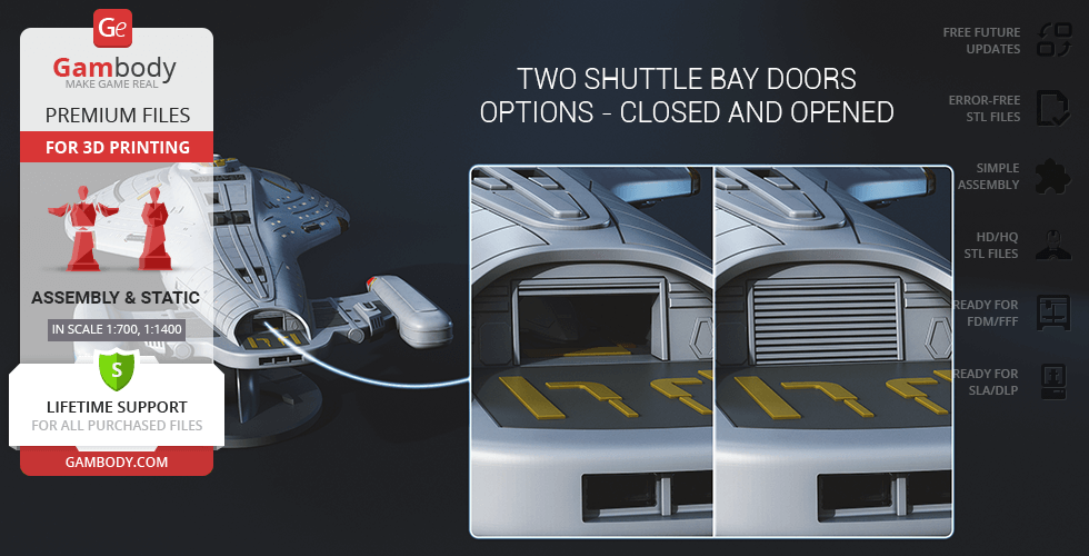
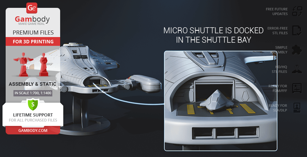
- Includes a highly detailed, open or closed shuttlebay door configuration complete with a tiny dockable micro shuttle, alongside an Aeroshuttle embedded into the saucer underside.
- Phaser arrays are separated from the main hull segments, vastly improving painting accessibility and allowing for sharp, flawless light-blocking edges.
- Built with optimized internal hollowing for clean electronics routing, paired with integrated anti-bleed seam rims to completely eliminate light leakage.
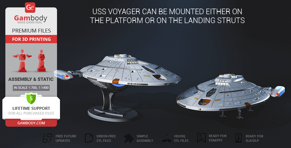
- The starship can be mounted directly on its advanced planetary landing struts or presented dynamically on a themed display stand designed to showcase the ship at an aggressive, cinematic angle.
Printing & assembly details:
- Provided as error-free STL files compatible with most 3D printers;
- Optimized part division minimizes support material and ensures smooth and precise surface detailing;
- The assembly parts in the FFF/FDM version come in the recommended print orientations for easy bed placement;
- Assembly manual in PDF and video formats is included for the FFF/FDM and DLP/SLA versions;
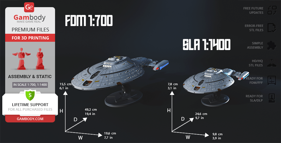
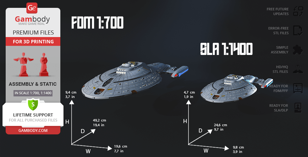
- The model is available in recommended scales — 1:700 for the FFF/FDM version and 1:1400 for the DLP/SLA versions.
What will you get after purchase?
- 4 versions of USS VoyagerSTL files for FFF/FDM and DLP/SLA — files for all versions are available for download after the purchase;
- STL files of high-poly USS Voyager model for 3D printing consist of 203 files;
- Sizes for:
- FFF/FDM Model Size: 196 mm wide, 118 mm high, 490 mm deep;
- FFF/FDM Platform Size: 114 mm wide, 77 mm high, 190 mm deep;
- DLP/SLA Model Size: 98 mm wide, 47 mm high, 246 mm deep;
- DLP/SLA Platform Size: 57 mm wide, 39 mm high, 99 mm deep;
- Assembly Manual for FFF/FDM and DLP/SLA versions in PDF and video formats;
- Detailed settings that we provide as a recommendation for Bambu Studio, Cura, Orca Slicer, PrusaSlicer, Simplify3D, and Slic3r for the best print;
- Full technical support from the Gambody Support Team.
Average customer rating (13 reviews)
4
Ratings breakdown
Click a star rating to filter reviews
Overall experience
Level of detail in the model
4.1
Model cut quality and assembly guide
4
Clarity and accuracy of the model page
4


 Verified purchase
 Level of detail in the model
5
Model cut quality and assembly guide
5
Clarity and accuracy of the model page
5


 Community Support Team
 The Maquis ship is a great suggestion and would definitely make a nice addition for Voyager fans. We’ve added this idea to our Wishlist so it can be considered by the contributing artists for future modeling.
Thank you again for sharing your idea and for your support. We’d be happy to see your finished Voyager build once it’s ready!
 Verified purchase
 Level of detail in the model
5
Model cut quality and assembly guide
3
Clarity and accuracy of the model page
4
Furthermore, printing the model as a solid piece created problems during assembly; the parts no longer fit together with perfect precision. I had to use modeling putty to fill the gaps. Even then, light still managed to leak through the seams. I ultimately had to use a type of sealant in conjunction with wide heat-shrink tubing to prevent any light from shining through the cracks. In the midsection of the ship, I was able to resolve this issue by installing a printed ring. The command bridge section was similarly affected, but I was able to make it light-tight using the same sealant method. COB LEDs were used to illuminate the entire forward and aft sections of the hull. The impulse engines were a real test of my patience; for these, I utilized rectangular LEDs. My goal was to ensure that the impulse thrusters would glow at both the rear and the front.
Consequently, three rectangular LEDs were installed on each side of the aft section: two LEDs for the wider rear portion and one LED for the narrower front portion. I carefully staggered the placement of the LEDs to achieve a nearly flawless, uniform glow. To prevent light bleed within this particularly narrow section, I encased the LEDs in heat-shrink tubing a very tight squeeze indeed. For the warp nacelles, a single red LED was installed at the front of each unit. However, preventing light bleed in this area also required the use of custom-cut heat-shrink tubing.
The blue lighting was likewise achieved using COB LEDs. To achieve this, I specifically designed a custom conduit to allow for the neat installation of this highly flexible LED. I also utilized a COB LED for the navigation deflector. To prevent light bleed into the interior of the *Voyager*, I employed a specialized shielding kit. I installed similar conduits within both the forward and lateral hull sections a technique I also applied to the aft section. The COB LEDs are seated within a conduit channel, with their connecting wires running alongside them. These conduits were glued in place in such a way that the COB LEDs project their light inward, thereby helping to diffuse the illumination. Naturally, it would be preferable if the design did not feature such narrow internal tunnels; ideally, the interior structure would be designed to remain open and accessible, making it much easier to work on. Nevertheless, painting the interior with black acrylic was not a viable option due to the presence of the small windows; even a minor slip of the brush would result in paint seeping out through the openings. To prevent light leakage through the exterior slits, it would be beneficial to incorporate a recessed groove on one side of the design and a corresponding cutout on the other, thereby ensuring that the internal light tunnels are completely sealed against the outside world.
I sincerely hope that revisions will be made to this model kit. If such improvements are implemented, I would gladly purchase a second unit to build the definitive, perfectly illuminated *Voyager* model.
I´m in Contact with Gambody to make this Model better it is :) I hope to get a new Model with some Fixes.
Community Support Team We truly appreciate how thoroughly you described the challenges with light bleed, wiring, internal channels, seams, LED placement, and the additional solutions you used during assembly. It is clear that a lot of time, testing, and creativity went into your build, and the final result looks very impressive.
We have forwarded your feedback to the model’s author, Paul Walther. He confirmed that your notes about preventing light bleed and making the model more hollow and accessible for wiring will be taken into consideration for a future update of the USS Voyager 3D Model.
Thank you again for taking the time to share your experience in such detail. Feedback like this helps us improve our models and provide better projects for the whole 3D printing community.
Verified purchase Level of detail in the model
4.9
Model cut quality and assembly guide
5
Clarity and accuracy of the model page
5


 This comment is from a user who hasn't purchased this model
 Verified purchase
 Level of detail in the model
4
Model cut quality and assembly guide
5
Clarity and accuracy of the model page
4.5
Community Support Team While lighting is an optional upgrade and depends on personal preference, it can significantly enhance the final look of the model. Although we don't offer an official lighting guide, you can follow this general suggestion to light up this 3D printing model in the attached scheme:
For additional tips on installing LED lights into your 3D printing projects, you can check out our blog article: https://www.gambody.com/blog/how-to-install-led-lights-in-a-3d-printed-model/
Here are some useful resources that cover the LED basics:
- https://www.smallscalelights.co.uk/led-basics/
- https://www.instructables.com/LED-Lighting-in-Plastic-Models/
- https://evandesigns.com/collections/hobby-leds
Here are some examples of the finished Starship projects from our Facebook community (feel free to join), where the enthusiasts showcase their works and share their setups.
- https://www.facebook.com/groups/183216945475583/posts/2380295805767675/
- https://www.facebook.com/groups/183216945475583/posts/1850258672104727/
- https://www.facebook.com/groups/183216945475583/posts/1752329141897681/
- https://www.facebook.com/groups/183216945475583/posts/1292967561167177/
Also, there is a Lighting video guide for the Enterprise D 3D model, as they share any design similarities, it may also be useful for you: https://www.youtube.com/watch?v=Ecz8ksf6wfc
You can also check out additional discussions on the LED topic in our Facebook group for some inspiration and insights from fellow hobbyists:
- https://www.facebook.com/groups/183216945475583/posts/1104024863394782/
- https://www.facebook.com/groups/183216945475583/posts/1210963856034215/
- https://www.facebook.com/groups/183216945475583/posts/1005241923273077/
Should you have any questions or need assistance with your Star Trek 3D printing project, don't hesitate to contact us – we're happy to help!
 Verified purchase
 Level of detail in the model
4
Model cut quality and assembly guide
4
Clarity and accuracy of the model page
4
This feedback is from a user who hasn't purchased this model Level of detail in the model
5
Model cut quality and assembly guide
5
Clarity and accuracy of the model page
5
 This feedback is from a user who hasn't purchased this model
 Level of detail in the model
1
Model cut quality and assembly guide
1
Clarity and accuracy of the model page
1
Verified purchase Level of detail in the model
5
Model cut quality and assembly guide
5
Clarity and accuracy of the model page
5
Verified purchase Level of detail in the model
4
Model cut quality and assembly guide
4
Clarity and accuracy of the model page
4
Verified purchase Level of detail in the model
4
Model cut quality and assembly guide
4
Clarity and accuracy of the model page
4
 This feedback is from a user who hasn't purchased this model
 Level of detail in the model
1
Model cut quality and assembly guide
1
Clarity and accuracy of the model page
1
Verified purchase Level of detail in the model
5
Model cut quality and assembly guide
5
Clarity and accuracy of the model page
5
 This feedback is from a user who hasn't purchased this model
 Level of detail in the model
5
Model cut quality and assembly guide
5
Clarity and accuracy of the model page
5
Below you'll find detailed slicing settings for Bambu Studio 2.0+, Orca Slicer 2.0+, UltiMaker Cura 5.0+, PrusaSlicer 2.0+, Slic3r 1.3+, Simplify3D 5.0+ to help you get the best results when printing this model. These settings are optimized specifically for this 3D model, but please note they may need slight adjustments depending on your printer or filament. When in doubt, refer to your printer's user manual.
To avoid printing issues and achieve the best quality, we highly recommend applying the following settings:
 Bambu Studio 2.0+
 For better quality use 0.12 mm layer height, for fast printing use 0.2 mm layer height. For pins and the Ge connectors, use 0.2 layer height.
120-150% of your Layer Height
But you can paint the seam if you want.
You have to calibrate this parameter
You have to calibrate this parameter
You have to calibrate this parameter
For pins and power elements of the structure, such as the vehicle frame, use 3 loop
Disabled for vehicles and enabled for characters
For 0,2 Layer Height
The parameters in this tab vary greatly, it all depends on the quality of your printer. For example, if you have a classic Ender3, stick to the minimum parameters, but if you have a newer printer, for example Anycubic cobra 3 v2, you can select the maximum recommended values
Settings for advanced users, change these parameters only if you have sufficient 3D printing expertise
Enable this parameter if your model requires supports
We also recommend placing and removing supports manually in some places using special button
1-2 loops for more thick support
Top Z distance = 1-1.3 layer Height. If the supports are hard to remove, try increasing this setting by 0.1-0,4 mm
Bottom Z distance = 1-1.3 layer Height. If the supports are hard to remove, try increasing this setting by 0.1-0,4 mm
You have to calibrate this parameter which one is better for your filament
Increase this parameter if the supports are hard to remove from walls
For PLA and PETG filament types
5-8 mm is optional for small prints that have bad adhesion to the build plate
You have to calibrate this parameter
Read the description on your filament roll
Read the description on your filament roll and increase this parameter for fast printers
Read the description on your filament roll and increase this parameter for fast printers
 Orca Slicer 2.0+
 For better quality use 0.12 mm layer height, for fast printing use 0.2 mm layer height. For pins and the Ge connectors, use 0.2 layer height.
120-150% of your Layer Height
But you can paint the seam if you want.
0.01-0.05 You have to calibrate this parameter
0.01-0.05 You have to calibrate this parameter
0.1-0.2 You have to calibrate this parameter
For pins and power elements of the structure, such as the vehicle frame, use 3 loop
Disabled for vehicles and ships, enabled for characters
For 0,2 Layer Height
For 0,2 Layer Height
The parameters in this tab vary greatly, it all depends on the quality of your printer. For example, if you have a classic Ender3, stick to the minimum parameters, but if you have a newer printer, for example, Anycubic Kobra 3 Or Bambulab A1, you can select the maximum recommended values.
Settings for advanced users, change these parameters only if you have sufficient 3D printing expertise
Enable this parameter if your model requires supports
We also recommend placing and removing supports manually in some places using special button
Top Z distance = 1-1.3 layer Height. If the supports are hard to remove, try increasing this setting by 0.1-0,4 mm
Bottom Z distance = 1-1.3 layer Height. If the supports are hard to remove, try increasing this setting by 0.1-0,4 mm
Increase this parameter if the supports are hard to remove from walls
For PLA and PETG filament types
5-8 mm is optional for small prints that have bad adhesion to the build plate
Read the description on your filament roll
Read the description on your filament roll and increase this parameter for fast printers
You have to calibrate this parameter
Read the description on your filament roll and increase this parameter for fast printers
Read the description on your filament roll
This field is filled in according to your printer specifications when you add it to the slicer.
You can add custom G-code here for the start and end of the print. However, be careful - this is for advanced users only!
You have to calibrate your printer using Ge retraction test models
Retraction Length: For direct-drive setups use 0.5 mm to 2.5 mm; for Bowden extruders use 5 to 7 mm
This is how fast the filament is pulled back—40-60 mm/s for direct drive and 30-50 mm/s for Bowden setups.
You have to calibrate this parameter: Reduce it until the printer starts to hit the parts with the nozzle during printing, then increase it by 0.2.
 UltiMaker Cura 5.0+
 For better quality use 0.12 mm layer height, for fast printing use 0.2 mm layer height. For pins and the Ge connectors, use 0.2 layer height.
120-150% of your Layer Height
To increase the strength of the print parts, use wall line count: 3
For pins and connectors use 50% Infill
These parameters are for standard PLA plastic. If you are using a different type of plastic, check the printing temperature recommended by the manufacturer. Also, read the description on your filament spool. For fast printers, add +30 °C to the current parameters.
The parameters in this tab vary greatly, it all depends on the quality of your printer. For example, if you have a classic Ender3, stick to the minimum parameters, but if you have a newer printer, for example Anycubic cobra 3 v3, you can select the maximum recommended values
Settings for advanced users, change these parameters only if you have sufficient 3D printing expertise.
You need to calibrate this parameter using Gambody test models. These values are average values for a Direct Drive extruder; for a Bowden extruder, the values should be increased.
You need to calibrate this parameter using Gambody test models. These values are average values for a Direct Drive extruder; for a Bowden extruder, the values should be increased.
Use this value other than 0 if your nozzle catches on the internal infill during travel moves. Try to keep this value as low as possible in height.
Use normal supports to support large, straight surfaces (most mechanical or technical parts).
You have to calibrate this parameter according to the capabilities of your printer and your filament, using a Gambody test models.
Use 1 instead of 0 if your supports are thin and tall. They will be harder to remove, but much stronger.
Top Z distance = 1-1.3 layer Height. If the supports are hard to remove, try increasing this setting by 0.1-0,4 mm
Increase this parameter if the supports are hard to remove from walls
Use tree supports to support complex objects, such as characters.
You have to calibrate this parameter according to the capabilities of your printer and your filament, using a Gambody test models.
Top Z distance = 1-1.3 layer Height. If the supports are hard to remove, try increasing this setting by 0.1-0,4 mm
Increase this parameter if the supports are hard to remove from walls
Use a skirt for all parts when printing on outdated printers.
Use a brim when printing thin but tall parts, as well as parts with a small bed adhesion area.
 PrusaSlicer 2.0+
 For better quality use 0.12 mm layer height, for fast printing use 0.2 mm layer height. For pins and the Ge connectors, use 0.2 layer height.
120-150% of your Layer Height
for 0.2 Layer Height
But you can paint the seam if you want.
(for PLA and PETG)
(5-8 mm is optional for small prints that have bad adhesion to the build plate)
Enable this parameter if your model requires supports
(45-50 degree)You have to calibrate this parameter according to the capabilities of your printer
and your filament, using a Gambody test models.
Top contact Z distance = 1-1.3 layer Height. If the supports are hard to remove, try
increasing this setting by 0.1-0,4 mm
Top contact Z distance = 1-1.3 layer Height. If the supports are hard to remove, try
increasing this setting by 0.1-0,4 mm
Increase this parameter if the supports are hard to remove from walls
The parameters in this tab vary greatly, it all depends on the quality of your printer. For example, if you have a classic Ender3, stick to the minimum parameters, but if you have a newer printer, for example Anycubic cobra 3 v3, you can select the maximum recommended values
Settings for advanced users, change these parameters only if you have sufficient 3D printing expertise. Use the minimum value for outdated printers without acceleration calibration, and the maximum value for modern printers if you need it.
These settings only work for 3D printers with multiple extruders
You can try setting all parameters in this section, except the First layer, to values between 0.75% of your nozzle diameter and 1.25% of your nozzle diameter. Adjusting them will help you work out the optimal parameters for the best quality for your print. As for the First layer, you can set it to 150% of the diameter of your nozzle for better adhesion to the build plate (for a nozzle with a diameter of 0.4 mm, the First layer extrusion width can be from 0.3 mm to 0.5 mm)
For better printing quality you have to calibrate this parameter using Gambody test model.
Check your filament manufacturer's temperature recommendations on the spool.
Cooling parameters depends on the material you use for printing.
*for PLA
 Slic3r 1.3+
 For better quality use 0.12 mm layer height, for fast printing use 0.2 mm layer height. For pins and the Ge connectors, use 0.2 layer height.
120-150% of your Layer Height
For 0.12 Layer Height
For 0.12 Layer Height
For pins and connectors use 50% Infill
Use skirt for outdated 3d printers
(5-8 mm is optional for small prints that have bad adhesion to the build plate)
Enable this parameter if your model requires supports
(45-60 degree)You have to calibrate this parameter according to the capabilities of your printer and your filament, using a Gambody test models
Contact Z distance = 1-1.3 layer Height. If the supports are hard to remove, try increasing this setting by 0.1-0,4 mm
The parameters in this tab vary greatly, it all depends on the quality of your printer. For example, if you have a classic Ender3, stick to the minimum parameters, but if you have a newer printer, for example Anycubic cobra 3 v3, you can select the maximum recommended values
Settings for advanced users, change these parameters only if you have sufficient 3D printing expertise. Use the minimum value for outdated printers without acceleration calibration, and the maximum value for modern printers if you need it.
You have to calibrate this parameter from 0.9 to 1.1 according to the capabilities of your printer and your filament, using a Gambody test models.
Check your filament manufacturer's temperature recommendations on the spool.
Cooling parameters depends on the material you use for printing.
Calibrate this value if you need to reduce or improve the adhesion between the plastic and the heat bed
Your current nozzle diameter
You need to calibrate this parameter using Gambody test models. These values are average values for a Direct Drive extruder; for a Bowden extruder, the values should be increased.
 Simplify3D 5.0+
 Your current nozzle diameter
You have to calibrate this parameter using Gambody test models.
You need to calibrate this parameter using Gambody test models. These values are average values for a Direct Drive extruder; for a Bowden extruder, the values should be increased.
For better quality use 0.12 mm layer height, for fast printing use 0.2 mm layer height. For pins and the Ge connectors, use 0.2 layer height.
For 0,2 Layer Height
For 0,2 Layer Height
To increase the strength of the print parts, use Outline Perimeters: 3
You can enable this parameter to print rounded or spherical models, as well as character models.
Use this option only if your parts are too tight. but better calibrate your printer extrusion
Use this option only if your parts are too tight. but better calibrate your printer extrusion
Use 2 and more if you want to create skirt instead brim
1-2 for skirt and 10-20 for brim
Use for wipe nozzle if you need
Use For ABS filament
For pins and connectors use 50% Infill
Top Z distance = 1-1.3 layer Height. If the supports are hard to remove, try increasing this setting by 0.1-0,4 mm
Calibrate your filament and detect optimal temperature for it
Average temperature for PLA filament
The parameters in this tab vary greatly, it all depends on the quality of your printer. For example, if you have a classic Ender3, stick to the minimum parameters, but if you have a newer printer, for example Anycubic cobra 3 v3, you can select the maximum recommended values
Settings for advanced users, change these parameters only if you have sufficient 3D printing expertise.
DLP/SLA
- Retains all versatility from the 1.0 version, including two hull options (smooth or with lettering), open/closed shuttlebay doors with the micro shuttle, an embedded Aeroshuttle, and positional warp nacelles.
- Completely hollowed-out internal hull design for unobstructed, bright LED placement instead of narrow wiring channels.
- Engineered with built-in anti-bleed internal rims along the seams to completely block light leakage between printed parts.
- Phaser arrays are now separated from the main hull segments, vastly improving painting accessibility and enabling clean, precise backlighting edges.
- Features a completely redesigned display stand that presents the starship at an aggressive, cinematic angle (can alternatively still be mounted on landing struts).
- Some model parts use separate connectors (part "_40_pin_a_X6_SLA" requires 6 copies; part "_41_pin_b_X4_SLA" requires 4 copies; part "_42_pin_c_X2_SLA" requires 2 copies).
FFF/FDM
- Retains all versatility from the 1.0 version, including two hull options (smooth or with lettering), open/closed shuttlebay doors with the micro shuttle, an embedded Aeroshuttle, and positional warp nacelles.
- Completely hollowed-out internal hull design for unobstructed, bright LED placement instead of narrow wiring channels.
- Engineered with built-in anti-bleed internal rims along the seams to completely block light leakage between printed parts.
- Phaser arrays are now separated from the main hull segments, vastly improving painting accessibility and enabling clean, precise backlighting edges.
- Features a completely redesigned display stand that presents the starship at an aggressive, cinematic angle (can alternatively still be mounted on landing struts).
- Some model parts use separate connectors (part "_50_pin_a_X6" requires 6 copies; part "_51_pin_b_X4_FDM" requires 4 copies; part "_52_pin_c_X2_FDM" requires 2 copies).
DLP/SLA
- Two hull design variants (smooth or with lettering), choice of closed or open shuttlebay doors with a micro shuttle, and an embedded Aeroshuttle.
- Standard horizontal display stand or deployable planetary landing struts.
- Positional nacelle pylons for flat or 30-degree warp-speed display.
- Built with internal structural tunnels and channels to route custom LED wiring loops through the ship's frame.
- The assembly parts are connected using specially designed integrated connectors that fit securely into the corresponding slots. Optionally, for added strength and rigidity, the static connections can be glued together.
FFF/FDM
- Two hull design variants (smooth or with lettering), choice of closed or open shuttlebay doors with a micro shuttle, and an embedded Aeroshuttle.
- Standard horizontal display stand or deployable planetary landing struts.
- Positional nacelle pylons for flat or 30-degree warp-speed display.
- Built with internal structural tunnels and channels to route custom LED wiring loops through the ship's frame.
- The assembly parts are connected using specially designed integrated connectors that fit securely into the corresponding slots. Optionally, for added strength and rigidity, the static connections can be glued together.
- Some model parts use separate connectors (part "_49_standPin_V1_X3_FDM" requires 3 copies; part "_50_pin_V1_X10_FDM" requires 10 copies; part "_51_pin_V2_X4_FDM" requires 4 copies; part "_52_pin_V3_X2_FDM" requires 2 copies; part "_53_standPin_V2_X2_01_FDM" requires 2 copies).