


Files
3D model format
Stereolithography (.stl)
Total files
Slicer settings
Mesh error check
Netfabb
Support
Lifetime support from Gambody team
Update requests
Available to verified buyers
Model complexity
Standard: balanced printing difficulty and moderate part count with assembly steps.
Model versions
FFF/FDM
Assembly method
Connectors, Glue
Features
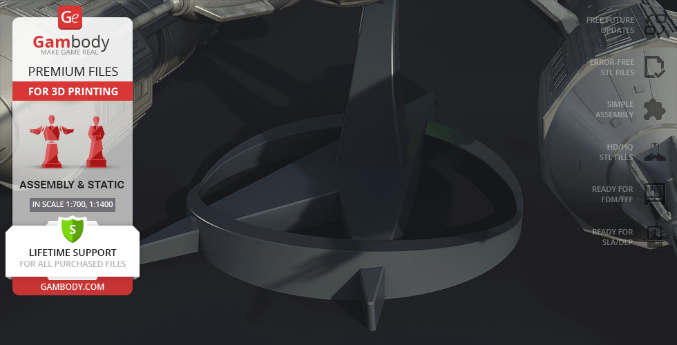
- The updated central nacelle has 4 vanes;
- Updated neutron blasters.
DLP/SLA
Assembly method
Connectors, Glue
Features
- The updated central nacelle has 4 vanes;
- Updated neutron blasters.
FFF/FDM
Assembly method
Connectors, Glue
Features
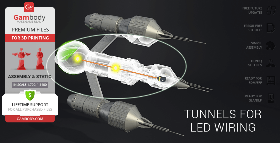
- Tunnels for LED wiring are provided to the Engine; the battery can be stored inside the main body;
DLP/SLA
Assembly method
Connectors, Glue
Features
- Tunnels for LED wiring are provided to the Engine; the battery can be stored inside the main body;
Additional details
Part of diorama
No
Special pack included
No
You will get instant access to the STL files of Liberator Blake's 7 3D Printing Model | Assembly after completing your purchase. Simply add the model to your cart and check out using PayPal, credit or debit card, Apple Pay, Google Pay, Alipay, or other available payment methods.
Watch the assembly video for Liberator Blake's 7 3D Printing Model | Assembly, and explore more tutorials, behind-the-scenes content, 3D printing timelapses, and painting guides on the official Gambody YouTube channel.
This 3D Model of Liberator Blake's 7 consists of files in StereoLithography (.Stl) format that is optimized for 3D printing.
Before printing the files, we strongly recommend reading the PRINTING DETAILS section.
WHAT WILL YOU GET AFTER PURCHASE?
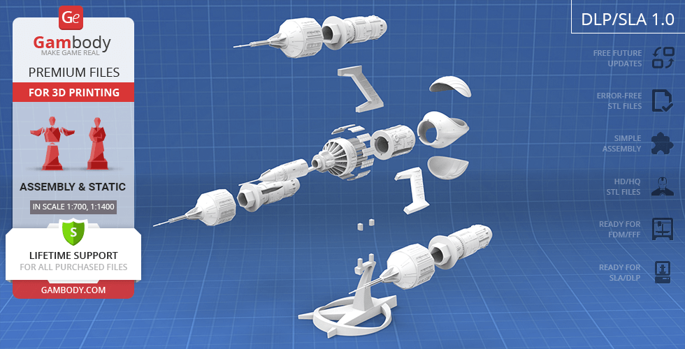
- 4 versions of Liberator Blake's 7 STL files for FFF/FDM and DLP/SLA - files for all versions are available for download after the purchase;
- STL files of high-poly Liberator Blake's 7 3D Model for 3D printing consist of 66 files;
- Sizes for:
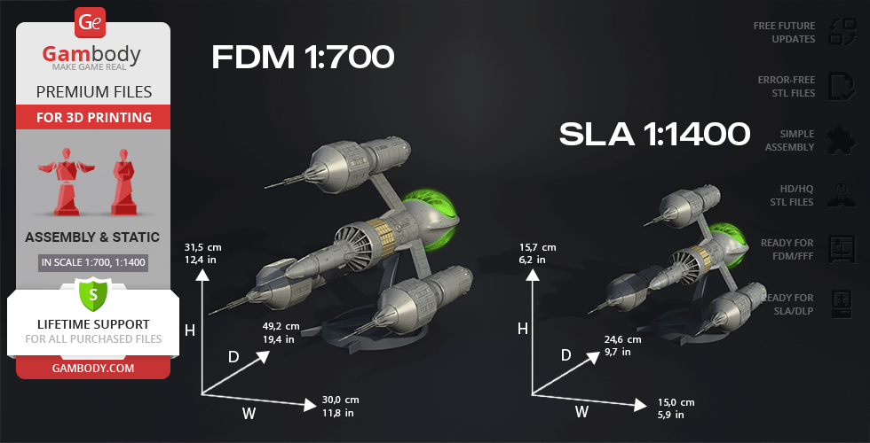
- FFF/FDM: 315 mm tall, 300 mm wide, 492 mm deep;
- DLP/SLA: 157 mm tall, 246 wide, 150 mm deep;
- AssemblyManual for FFF/FDM 1.0 and DLP/SLA 1.0 versions in PDF and video formats;
- Detailed settings that we provide as a recommendation for Cura, Simplify3D, Slic3r and PrusaSlicer for the best print;
- Full technical support from the Gambody Support Team.
Detailed information about this 3D printing model is available in the DESCRIPTION section.
Before printing, take a look at Printing Details for recommended settings and tips to achieve better results.
ABOUT THIS 3D MODEL
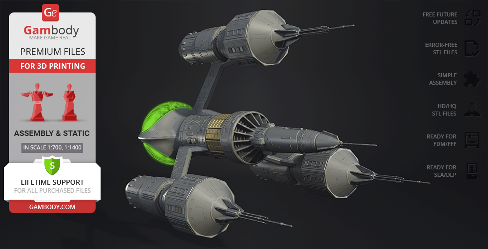
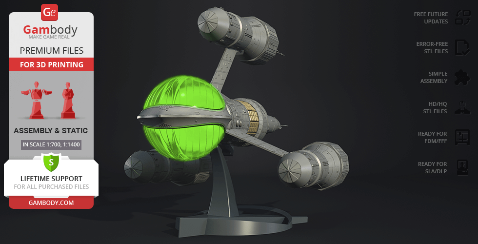
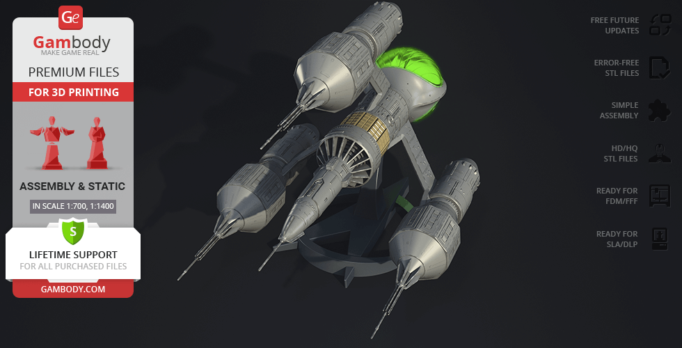
Blake's 7 is a British science fiction television series that ran for four seasons from 1978 to 1981. The show was created by Terry Nation, who is best known as the creator of the Daleks in the long-running BBC series Doctor Who. The series follows the adventures of a group of seven criminals and outcasts who band together to fight against the oppressive Terran Federation.
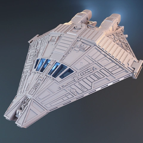
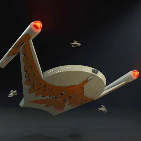
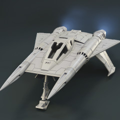
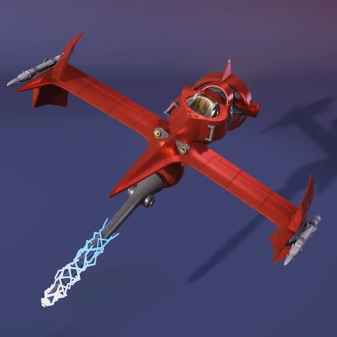
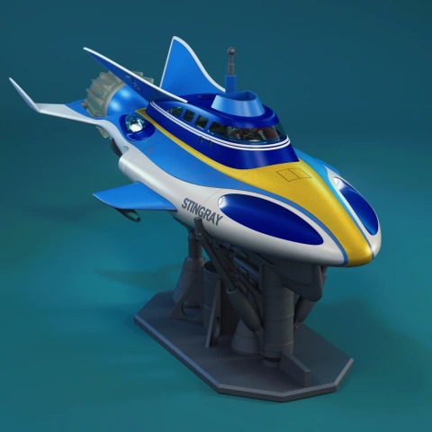
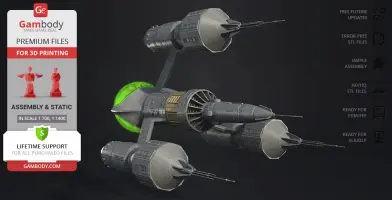
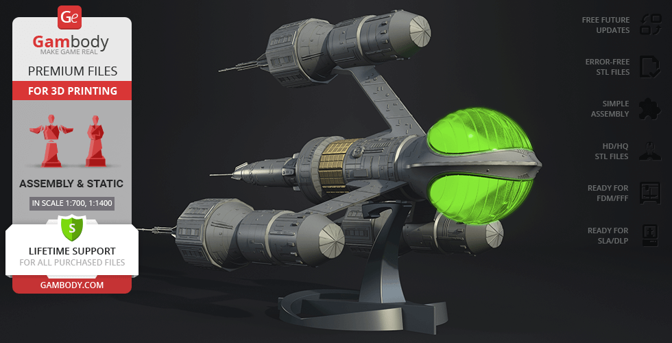
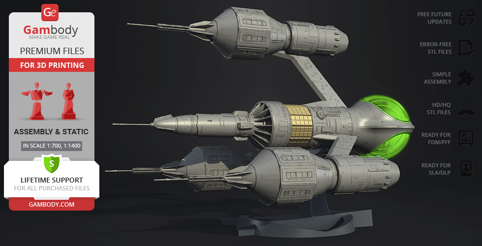
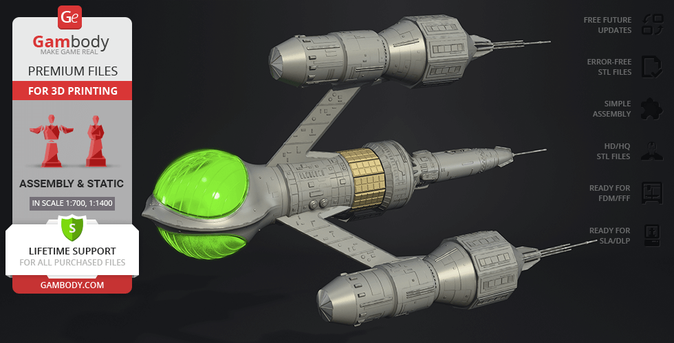
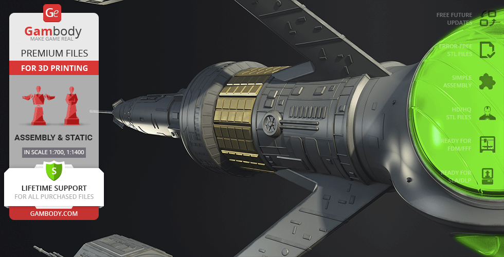
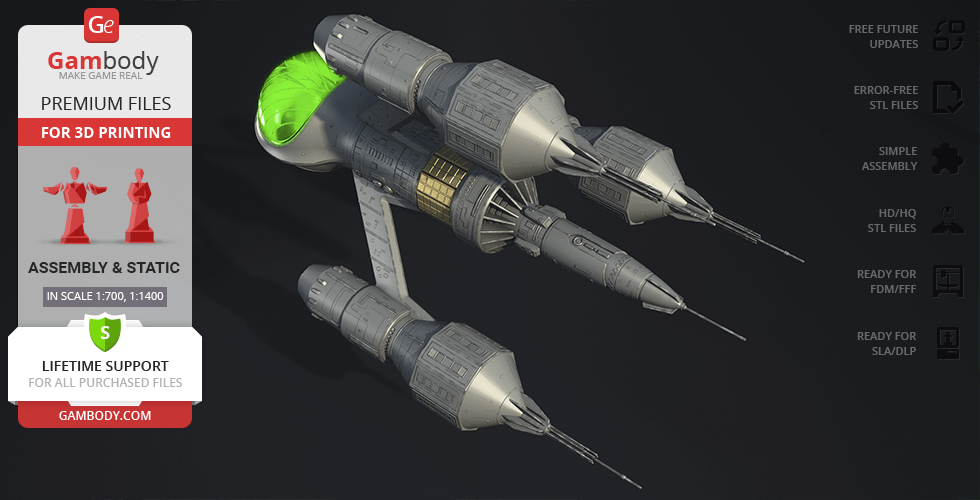
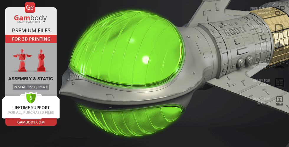
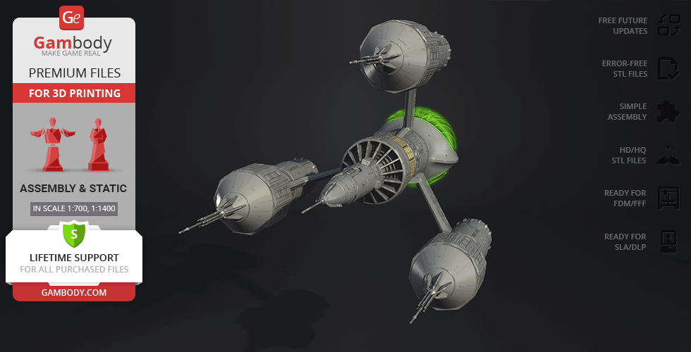
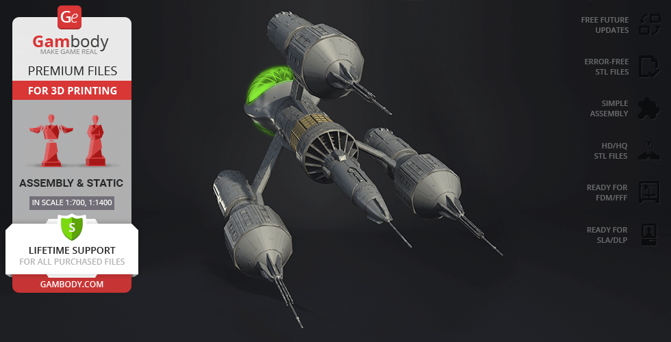
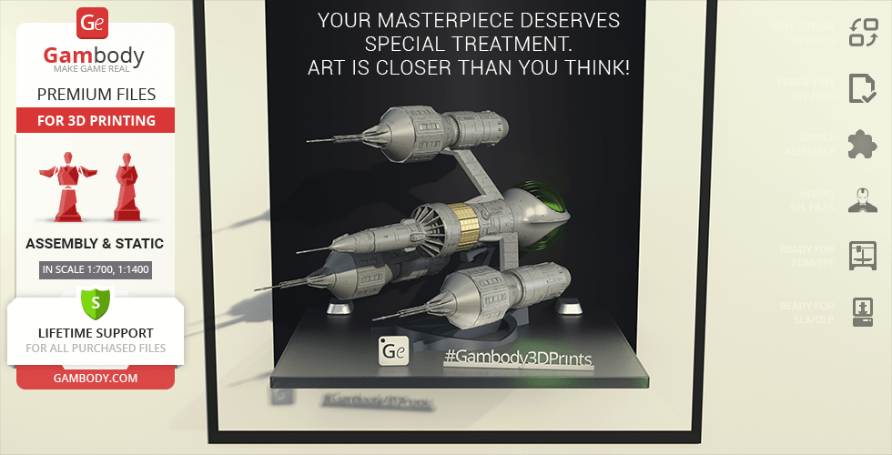
In the series Blake's 7, the Liberator is a highly advanced and powerful spaceship that serves as the primary setting and mode of transportation for the main characters. It is said to be "the most powerful fighting ship in the galaxy" and is equipped with a wide range of weapons and technology. The Liberator is also able to travel faster than the speed of light, allowing the crew to quickly cover vast distances and evade pursuit. The ship's design is sleek and angular, with a distinctive, elongated shape. The Liberator plays a crucial role in the series, as it serves as both a symbol of the crew's freedom and a tool in their fight against the oppressive Terran Federation.
ADAPTATION FOR 3D PRINTING
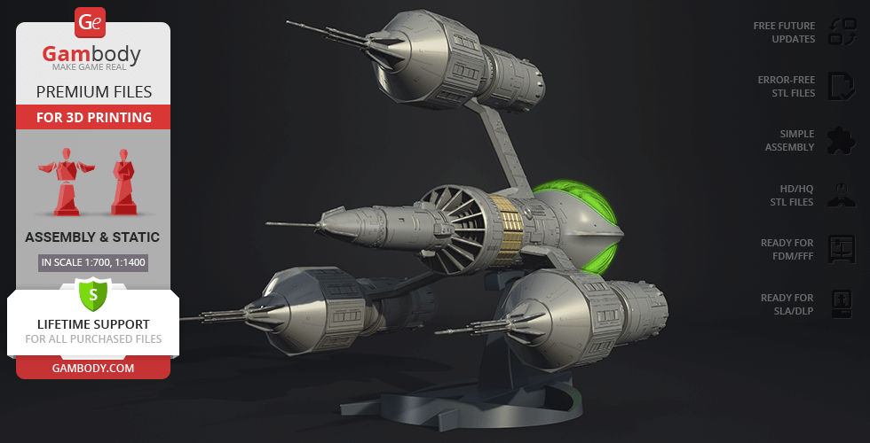
Liberator Blake’s 7 for 3D printing is a static assembly model and its moderation and adaptation for different types of 3D printers took the Gambody team 24 hours in total.
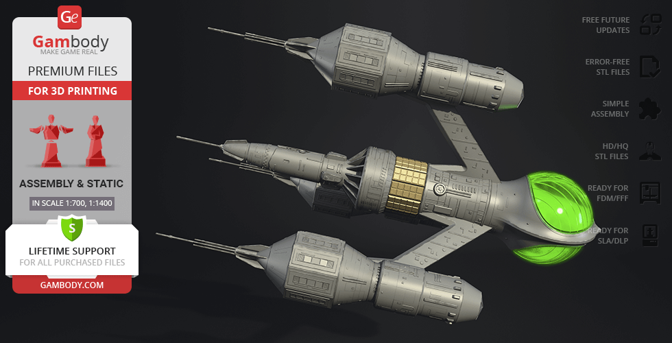
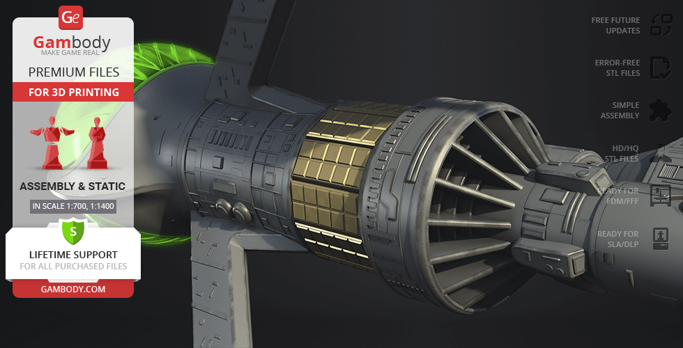
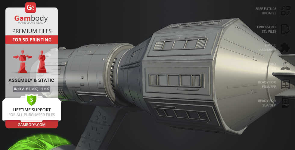
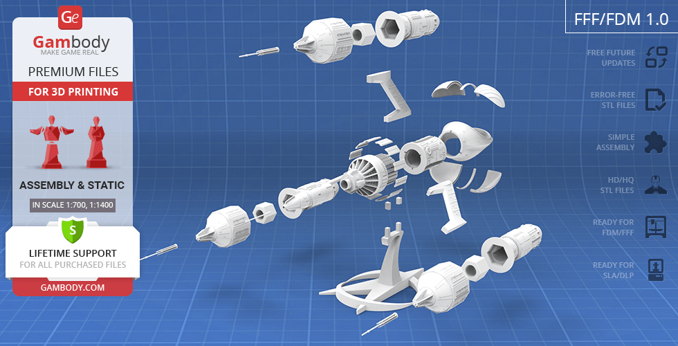
For you to receive the cleanest 3D printing result possible, minimize the amount of filament needed for generated support, the spaceship was divided into convenient assembly parts.
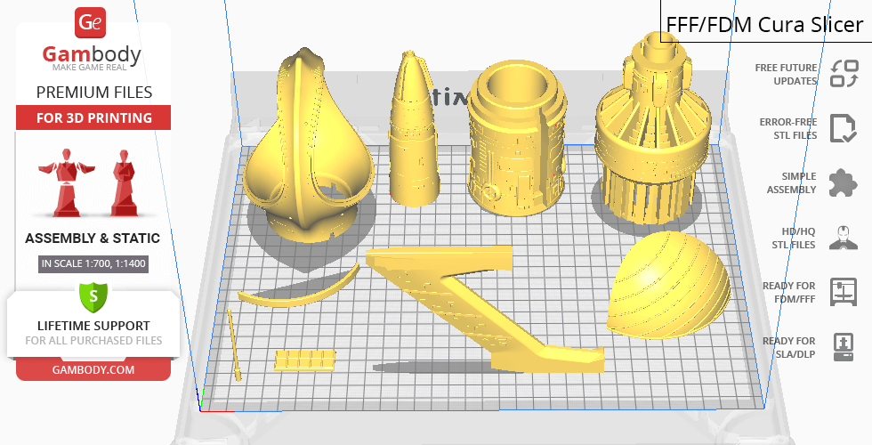
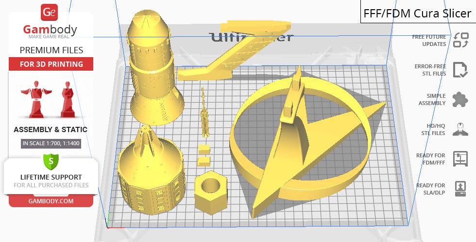
All assembly parts in the FFF/FDM 1.0 version are provided in STL files in recommended positions that were worked out in order to ensure the smoothness of the details’ surfaces after printing and that the 3D printing beginners won't face difficulties when placing the parts on a build plate. When downloading any model's file you will also receive "Assembly Manual" for FFF/FDM 1.0 and DLP/SLA 1.0 versions in PDF format. We highly recommend that you get acquainted with the “Assembly video” and "Assembly Manual" before getting down to Liberator Blake’s 7.
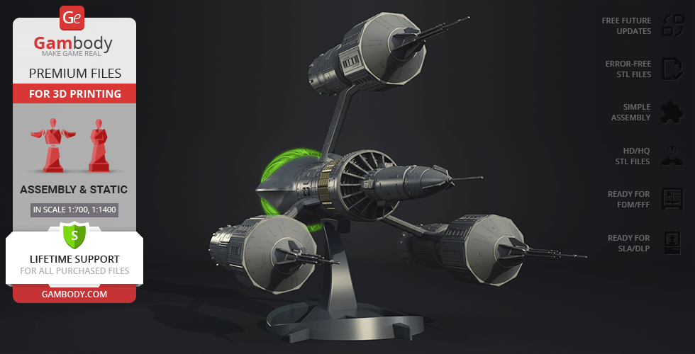
The model is saved in STL files, a format supported by most 3D printers. All STL files for 3D printing have been checked in Netfabb and no errors were shown.
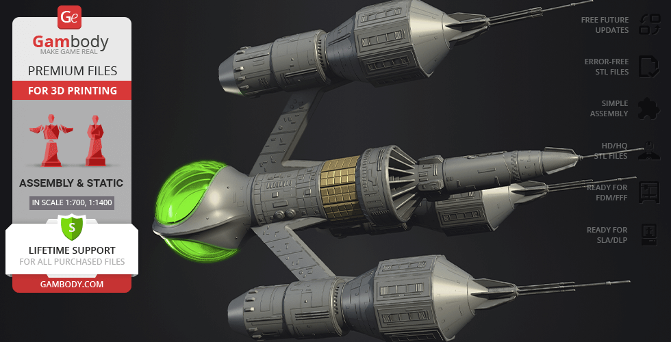
The model’s scale was calculated from the length of Liberator Blake’s 7. The 3D printing model’s chosen scales are 1:700 for the FFF/FDM version and 1:1400 for the DLP/SLA version.
VERSIONS’ SPECIFICATIONS
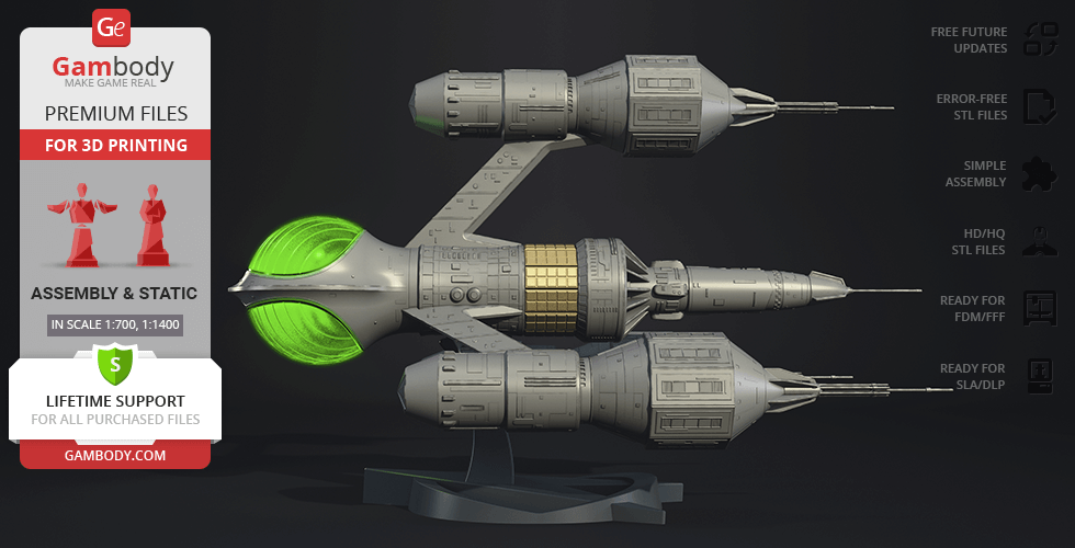
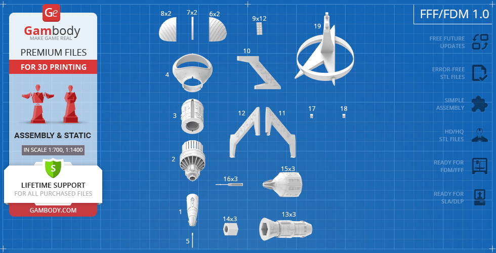
FFF/FDM 1.1 version features:
- Contains 19 parts;
- A printed model is 315 mm tall, 300 mm wide, 492 mm deep;
- The updated central nacelle has 4 vanes;
- Updated neutron blasters.
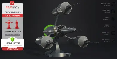
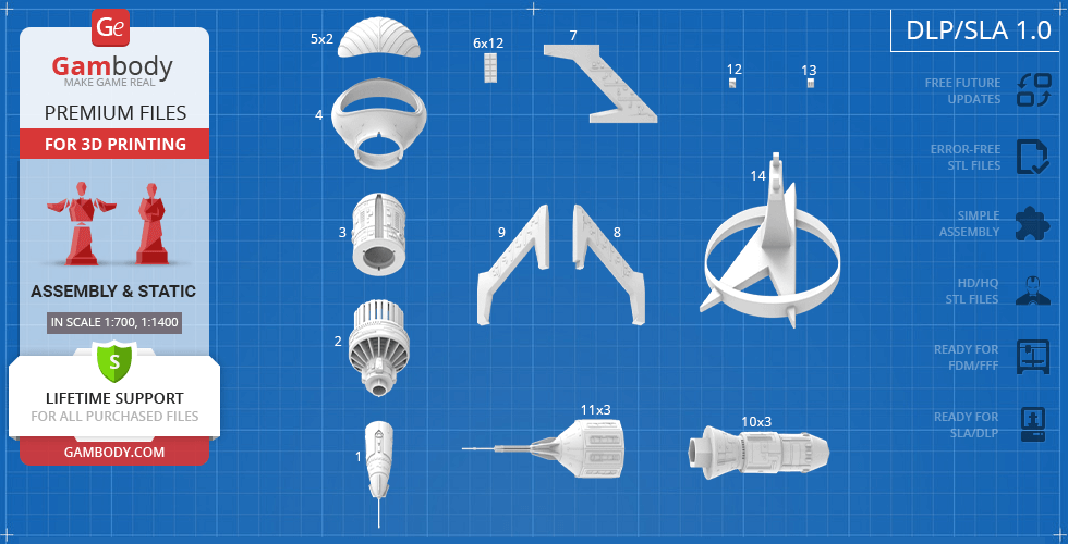
DLP/SLA 1.1 version features:
- Contains 14 parts;
- A printed model is 157 mm tall, 150 wide, 246 mm deep;
- The updated central nacelle has 4 vanes;
- Updated neutron blasters.
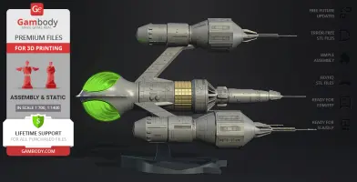
FFF/FDM 1.0 version features:
- Contains 19 parts;
- A printed model is 315 mm tall, 300 mm wide, 492 mm deep;
- Tunnels for LED wiring are provided to the Engine; the battery can be stored inside the main body;
- All parts are divided in such a way that you will print them with the smallest number of support structures.
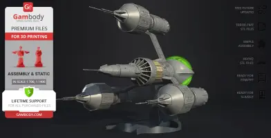
DLP/SLA 1.0 version features:
- Contains 14 parts;
- A printed model is 157 mm tall, 150 wide, 246 mm deep;
- Tunnels for LED wiring are provided to the Engine; the battery can be stored inside the main body;
- All parts are divided in such a way to fit the build plates and to ensure that support structures are generated where needed.
You can get the model of Liberator Blake’s 7 for 3D Printing immediately after the purchase! Just click the green Buy button in the top-right corner of the model’s page. You can pay with PayPal or your credit card.
Watch the tutorial on how to assemble Liberator Blake’s 7 3D Printing Model on Gambody YouTube channel.
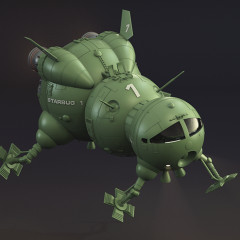
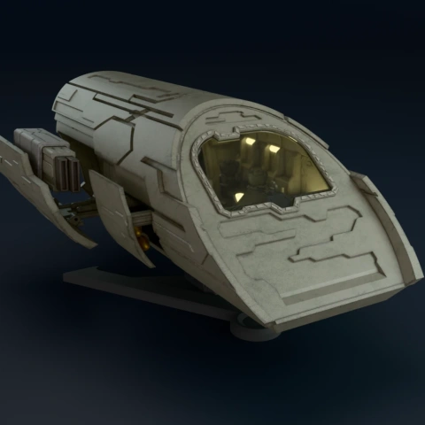
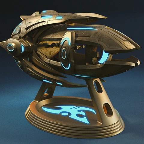
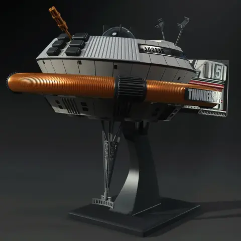
Also, you may like the Red Dwarf and Starbug3D Printing Models,andother Spaceships models and figurines for 3D Printing.
_______
FAQ:
Where can I print a model if I have no printer?
How to get started with 3D printing?
Average customer rating (3 reviews)
5
Ratings breakdown
Click a star rating to filter reviews
Overall experience
Level of detail in the model
4.8
Model cut quality and assembly guide
4.9
Clarity and accuracy of the model page
4.9
Level of detail in the model
4.5
Model cut quality and assembly guide
4.8
Clarity and accuracy of the model page
4.7
Notes:
- It's a big model!! Which is awesome
- Lots of detail!
- The front antenna had a tendency to break (it's quite a small piece) and when printed was a bit bubbly but that's barely noticeable
- Pieces 2 and 3 of the main body slot together but the connecting protrusion/groove is quite short, meaning you need a lot of glue to hold it together, it would be great if the connection section was longer/depper to make that connection more robust
Question for the team: I used your Bambu Settings guide PDF to chnge the default settings of my P2S to print this, b ut I noticed some of those settings were quite conservative (the full model took a few days of printing to complete). Is the guide up-to-date and does it take into account to P2S model?
All in all an amazing model and I'm proud tofinally have my own Liberator, which has been my favourtie spacecraft since i was a child!
We appreciate your comments regarding the front antenna and the connection between parts #2 and #3 of the main body. Your note about the connection depth is especially helpful, and we’ll be sure to forward this suggestion to the model’s designer for consideration in future updates.
Regarding the Bambu settings guide: yes, you’re absolutely right – the Gambody-recommended settings are intentionally more conservative than the default Bambu profiles. These settings are designed to be universal, taking into account a wide range of models, printers, and user experience levels. They prioritize print reliability, reduced vibration, and higher success rates, especially for complex geometry, thin elements, and fine details. This approach is also meant to be safer and more forgiving for beginners.
For more experienced users, like yourself as you continue to grow in the hobby, you’re always welcome to fine-tune and optimize these settings based on your printer’s capabilities and your own experience. Faster speeds and more aggressive parameters can absolutely be achieved once you’re confident with how your machine behaves.
Thank you again for your thoughtful feedback and kind words. It’s great to know the Liberator has finally taken its place in your collection – and we’re proud to have been part of that journey. If you have any further questions or ideas, we’re always happy to hear them.
Level of detail in the model
5
Model cut quality and assembly guide
5
Clarity and accuracy of the model page
5
Level of detail in the model
5
Model cut quality and assembly guide
5
Clarity and accuracy of the model page
5
Below you'll find detailed slicing settings for Bambu Studio 2.0+, Orca Slicer 2.0+, UltiMaker Cura 5.0+, PrusaSlicer 2.0+, Slic3r 1.3+, Simplify3D 5.0+ to help you get the best results when printing this model. These settings are optimized specifically for this 3D model, but please note they may need slight adjustments depending on your printer or filament. When in doubt, refer to your printer's user manual.
To avoid printing issues and achieve the best quality, we highly recommend applying the following settings:
For better quality use 0.12 mm layer height, for fast printing use 0.2 mm layer height. For pins and the Ge connectors, use 0.2 layer height.
120-150% of your Layer Height
But you can paint the seam if you want.
You have to calibrate this parameter
You have to calibrate this parameter
You have to calibrate this parameter
For pins and power elements of the structure, such as the vehicle frame, use 3 loop
Disabled for vehicles and enabled for characters
For 0,2 Layer Height
The parameters in this tab vary greatly, it all depends on the quality of your printer. For example, if you have a classic Ender3, stick to the minimum parameters, but if you have a newer printer, for example Anycubic cobra 3 v2, you can select the maximum recommended values
Settings for advanced users, change these parameters only if you have sufficient 3D printing expertise
Enable this parameter if your model requires supports
We also recommend placing and removing supports manually in some places using special button
1-2 loops for more thick support
Top Z distance = 1-1.3 layer Height. If the supports are hard to remove, try increasing this setting by 0.1-0,4 mm
Bottom Z distance = 1-1.3 layer Height. If the supports are hard to remove, try increasing this setting by 0.1-0,4 mm
You have to calibrate this parameter which one is better for your filament
Increase this parameter if the supports are hard to remove from walls
For PLA and PETG filament types
5-8 mm is optional for small prints that have bad adhesion to the build plate
You have to calibrate this parameter
Read the description on your filament roll
Read the description on your filament roll and increase this parameter for fast printers
Read the description on your filament roll and increase this parameter for fast printers
For better quality use 0.12 mm layer height, for fast printing use 0.2 mm layer height. For pins and the Ge connectors, use 0.2 layer height.
120-150% of your Layer Height
But you can paint the seam if you want.
0.01-0.05 You have to calibrate this parameter
0.01-0.05 You have to calibrate this parameter
0.1-0.2 You have to calibrate this parameter
For pins and power elements of the structure, such as the vehicle frame, use 3 loop
Disabled for vehicles and ships, enabled for characters
For 0,2 Layer Height
For 0,2 Layer Height
The parameters in this tab vary greatly, it all depends on the quality of your printer. For example, if you have a classic Ender3, stick to the minimum parameters, but if you have a newer printer, for example, Anycubic Kobra 3 Or Bambulab A1, you can select the maximum recommended values.
Settings for advanced users, change these parameters only if you have sufficient 3D printing expertise
Enable this parameter if your model requires supports
We also recommend placing and removing supports manually in some places using special button
Top Z distance = 1-1.3 layer Height. If the supports are hard to remove, try increasing this setting by 0.1-0,4 mm
Bottom Z distance = 1-1.3 layer Height. If the supports are hard to remove, try increasing this setting by 0.1-0,4 mm
Increase this parameter if the supports are hard to remove from walls
For PLA and PETG filament types
5-8 mm is optional for small prints that have bad adhesion to the build plate
Read the description on your filament roll
Read the description on your filament roll and increase this parameter for fast printers
You have to calibrate this parameter
Read the description on your filament roll and increase this parameter for fast printers
Read the description on your filament roll
This field is filled in according to your printer specifications when you add it to the slicer.
You can add custom G-code here for the start and end of the print. However, be careful - this is for advanced users only!
You have to calibrate your printer using Ge retraction test models
Retraction Length: For direct-drive setups use 0.5 mm to 2.5 mm; for Bowden extruders use 5 to 7 mm
This is how fast the filament is pulled back—40-60 mm/s for direct drive and 30-50 mm/s for Bowden setups.
You have to calibrate this parameter: Reduce it until the printer starts to hit the parts with the nozzle during printing, then increase it by 0.2.
For better quality use 0.12 mm layer height, for fast printing use 0.2 mm layer height. For pins and the Ge connectors, use 0.2 layer height.
120-150% of your Layer Height
To increase the strength of the print parts, use wall line count: 3
For pins and connectors use 50% Infill
These parameters are for standard PLA plastic. If you are using a different type of plastic, check the printing temperature recommended by the manufacturer. Also, read the description on your filament spool. For fast printers, add +30 °C to the current parameters.
The parameters in this tab vary greatly, it all depends on the quality of your printer. For example, if you have a classic Ender3, stick to the minimum parameters, but if you have a newer printer, for example Anycubic cobra 3 v3, you can select the maximum recommended values
Settings for advanced users, change these parameters only if you have sufficient 3D printing expertise.
You need to calibrate this parameter using Gambody test models. These values are average values for a Direct Drive extruder; for a Bowden extruder, the values should be increased.
You need to calibrate this parameter using Gambody test models. These values are average values for a Direct Drive extruder; for a Bowden extruder, the values should be increased.
Use this value other than 0 if your nozzle catches on the internal infill during travel moves. Try to keep this value as low as possible in height.
Use normal supports to support large, straight surfaces (most mechanical or technical parts).
You have to calibrate this parameter according to the capabilities of your printer and your filament, using a Gambody test models.
Use 1 instead of 0 if your supports are thin and tall. They will be harder to remove, but much stronger.
Top Z distance = 1-1.3 layer Height. If the supports are hard to remove, try increasing this setting by 0.1-0,4 mm
Increase this parameter if the supports are hard to remove from walls
Use tree supports to support complex objects, such as characters.
You have to calibrate this parameter according to the capabilities of your printer and your filament, using a Gambody test models.
Top Z distance = 1-1.3 layer Height. If the supports are hard to remove, try increasing this setting by 0.1-0,4 mm
Increase this parameter if the supports are hard to remove from walls
Use a skirt for all parts when printing on outdated printers.
Use a brim when printing thin but tall parts, as well as parts with a small bed adhesion area.
For better quality use 0.12 mm layer height, for fast printing use 0.2 mm layer height. For pins and the Ge connectors, use 0.2 layer height.
120-150% of your Layer Height
for 0.2 Layer Height
But you can paint the seam if you want.
(for PLA and PETG)
(5-8 mm is optional for small prints that have bad adhesion to the build plate)
Enable this parameter if your model requires supports
(45-50 degree)You have to calibrate this parameter according to the capabilities of your printer
and your filament, using a Gambody test models.
Top contact Z distance = 1-1.3 layer Height. If the supports are hard to remove, try
increasing this setting by 0.1-0,4 mm
Top contact Z distance = 1-1.3 layer Height. If the supports are hard to remove, try
increasing this setting by 0.1-0,4 mm
Increase this parameter if the supports are hard to remove from walls
The parameters in this tab vary greatly, it all depends on the quality of your printer. For example, if you have a classic Ender3, stick to the minimum parameters, but if you have a newer printer, for example Anycubic cobra 3 v3, you can select the maximum recommended values
Settings for advanced users, change these parameters only if you have sufficient 3D printing expertise. Use the minimum value for outdated printers without acceleration calibration, and the maximum value for modern printers if you need it.
These settings only work for 3D printers with multiple extruders
You can try setting all parameters in this section, except the First layer, to values between 0.75% of your nozzle diameter and 1.25% of your nozzle diameter. Adjusting them will help you work out the optimal parameters for the best quality for your print. As for the First layer, you can set it to 150% of the diameter of your nozzle for better adhesion to the build plate (for a nozzle with a diameter of 0.4 mm, the First layer extrusion width can be from 0.3 mm to 0.5 mm)
For better printing quality you have to calibrate this parameter using Gambody test model.
Check your filament manufacturer's temperature recommendations on the spool.
Cooling parameters depends on the material you use for printing.
*for PLA
For better quality use 0.12 mm layer height, for fast printing use 0.2 mm layer height. For pins and the Ge connectors, use 0.2 layer height.
120-150% of your Layer Height
For 0.12 Layer Height
For 0.12 Layer Height
For pins and connectors use 50% Infill
Use skirt for outdated 3d printers
(5-8 mm is optional for small prints that have bad adhesion to the build plate)
Enable this parameter if your model requires supports
(45-60 degree)You have to calibrate this parameter according to the capabilities of your printer and your filament, using a Gambody test models
Contact Z distance = 1-1.3 layer Height. If the supports are hard to remove, try increasing this setting by 0.1-0,4 mm
The parameters in this tab vary greatly, it all depends on the quality of your printer. For example, if you have a classic Ender3, stick to the minimum parameters, but if you have a newer printer, for example Anycubic cobra 3 v3, you can select the maximum recommended values
Settings for advanced users, change these parameters only if you have sufficient 3D printing expertise. Use the minimum value for outdated printers without acceleration calibration, and the maximum value for modern printers if you need it.
You have to calibrate this parameter from 0.9 to 1.1 according to the capabilities of your printer and your filament, using a Gambody test models.
Check your filament manufacturer's temperature recommendations on the spool.
Cooling parameters depends on the material you use for printing.
Calibrate this value if you need to reduce or improve the adhesion between the plastic and the heat bed
Your current nozzle diameter
You need to calibrate this parameter using Gambody test models. These values are average values for a Direct Drive extruder; for a Bowden extruder, the values should be increased.
Your current nozzle diameter
You have to calibrate this parameter using Gambody test models.
You need to calibrate this parameter using Gambody test models. These values are average values for a Direct Drive extruder; for a Bowden extruder, the values should be increased.
For better quality use 0.12 mm layer height, for fast printing use 0.2 mm layer height. For pins and the Ge connectors, use 0.2 layer height.
For 0,2 Layer Height
For 0,2 Layer Height
To increase the strength of the print parts, use Outline Perimeters: 3
You can enable this parameter to print rounded or spherical models, as well as character models.
Use this option only if your parts are too tight. but better calibrate your printer extrusion
Use this option only if your parts are too tight. but better calibrate your printer extrusion
Use 2 and more if you want to create skirt instead brim
1-2 for skirt and 10-20 for brim
Use for wipe nozzle if you need
Use For ABS filament
For pins and connectors use 50% Infill
Top Z distance = 1-1.3 layer Height. If the supports are hard to remove, try increasing this setting by 0.1-0,4 mm
Calibrate your filament and detect optimal temperature for it
Average temperature for PLA filament
The parameters in this tab vary greatly, it all depends on the quality of your printer. For example, if you have a classic Ender3, stick to the minimum parameters, but if you have a newer printer, for example Anycubic cobra 3 v3, you can select the maximum recommended values
Settings for advanced users, change these parameters only if you have sufficient 3D printing expertise.
DLP/SLA
- The updated central nacelle has 4 vanes;
- Updated neutron blasters.
FFF/FDM
- The updated central nacelle has 4 vanes;
- Updated neutron blasters.
DLP/SLA
- Tunnels for LED wiring are provided to the Engine; the battery can be stored inside the main body;
FFF/FDM
- Tunnels for LED wiring are provided to the Engine; the battery can be stored inside the main body;