


Files
3D model format
Stereolithography (.stl)
Total files
Slicer settings
Mesh error check
Netfabb
Support
Lifetime support from Gambody team
Update requests
Available to verified buyers
Model complexity
Standard: balanced printing difficulty and moderate part count with assembly steps.
Model versions
FFF/FDM
Assembly method
Ge-Locks
Features
DLP/SLA
Assembly method
Glue
Features
SLS
Assembly method
Solid
Features
Additional details
Part of diorama
No
Special pack included
No
You will get instant access to the STL files of USS Sulaco 3D Printing Model | Assembly after completing your purchase. Simply add the model to your cart and check out using PayPal, credit or debit card, Apple Pay, Google Pay, Alipay, or other available payment methods.
Watch the assembly video for USS Sulaco 3D Printing Model | Assembly, and explore more tutorials, behind-the-scenes content, 3D printing timelapses, and painting guides on the official Gambody YouTube channel.
This 3D Model consists of files in StereoLithography (.Stl) format that is optimized for 3D printing.
Before printing the files, we strongly recommend reading the PRINTING DETAILS section.
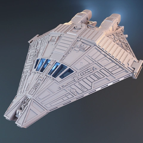
USS Sulaco 3D Printing Model comes in 3 versions for FFF/FDM and DLP/SLA/SLS 3D printers. STL files of all versions are available for download after the purchase.
Detailed information about this 3D printing model is available in the DESCRIPTION section.
Before printing, take a look at Printing Details for recommended settings and tips to achieve better results.
ABOUT THIS 3D MODEL
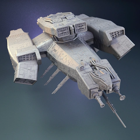
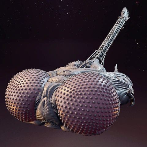
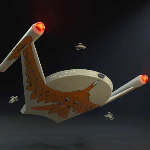
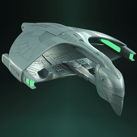
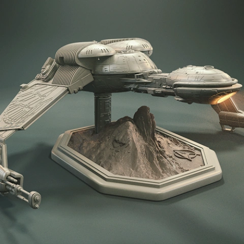
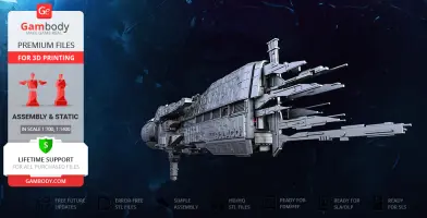
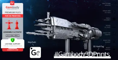
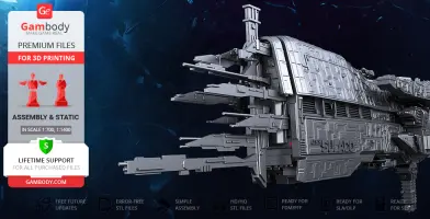
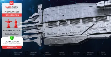
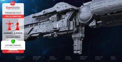
The USS Sulaco is a fictional spacecraft that appears within Alien vs. Predator universe, namely was an important setting in the course of 1986 American sci-fi film ‘Aliens’. Aside from being a troop transport ship, this Conestoga-class vessel mainly served as a carrier for rapid deployment of two UD4L Cheyenne dropships. While exploring the vast distances of space the USS Sulaco earned rather an infamous reputation being the most unlucky ship of the Colonial Marines fleet and was eventually destroyed in a confrontation with the USS Sephora. Nevertheless, the carrier of the 2nd Battalion Bravo Team with its unique shark-like design remained well-loved by franchise fans and still serves as a source of inspiration for creators. The author of the USS Sulaco model for 3D printing dedicated to the project 136 hours in total and made sure to capture the trademark elongated form of the frigate that makes it look like a 'gun in space'. The 3D printing spacecraft is depicted bulky and heavily armoured with its sensor array full of long and sharp antennae. The exterior design of the multi-role space vessel for 3D printing was thoroughly considered for your future model in the collection to boast of highly-detailed spaceframe composition of the hull armour. The 3D artist made sure that the USS Sulaco is ready to add to your impressive AvP 3D printed collection - the model’s design allows you to introduce the LEDs that would significantly enhance the way the spaceship will be displayed on the special two-part stand. You must already be eager to start printing - go order the STL files!
ADAPTATION FOR 3D PRINTING
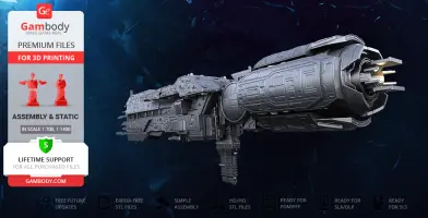
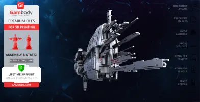
USS Sulaco for 3D printing is a static assembly model and its moderation and adaptation for different types of 3D printers took Gambody team 44 hours in total. For you to receive the cleanest printing result possible and to minimise the amount of filament needed for generated support the Conestoga-class starship model was divided into many assembly parts, e.g. its twin railguns located in dorsal and ventral turrets, each sensor and antennae that comprise the sensor array etc. are provided as separate STL files. There can be found special tunnels throughout the body of the USS Sulaco leading into the Westingland A-59 3.6 terawatt fusion reactor and sensor array area that were designed by our team for you to easily introduce LED wiring. For you to conveniently display the model among your 3D printed starship or AvP collection there was prepared a special two-piece stand for the ship with the design made to resemble the hull armour of Sulaco. All assembly parts are provided in STL files in recommended positions that were worked out so to ensure the smoothness of the details’ surfaces after printing and so that the 3D printing beginners won't face difficulties when placing the parts on a build plate.
The model is saved in STL files, a format supported by most 3D printers. All STL files for 3D printing have been checked in Netfabb and no errors were shown.
The model's scale was calculated from the actual length of the USS Sulaco that is 385000 mm. The 3D printing model's chosen scale is 1/700 for FFF/FDM version and 1/1400 for DLP/SLA/SLS version.
VERSIONS' SPECIFICATIONS
FFF/FDM 1.0 version features:
- Contains 24 parts;
- A printed ship is 165 mm tall, 76 mm wide, 548 mm deep;
- Assembly kit includes lock 24_Ge_lock_10H_x18 to connect the model's parts securely without glue that needs to be printed 18 times;
- Model is made hollow for you to introduce LED wiring throughout the spaceship's body;
- Made with a two-part stand to conveniently display the ship among your spacecraft fleet;
- All parts are divided in such a way that you will print them with the smallest number of support structures.
DLP/SLA 1.0 version features:
- Contains 12 parts;
- A printed model is 83 mm tall, 38 mm wide, 274 mm deep;
- Made with a two-part stand to conveniently display the ship among your spacecraft fleet;
- All parts are divided in such a way to fit the build plates and to ensure that support structures are generated where needed.
SLS 1.0 version features:
- Made as a solid one-piece model;
- A printed model is 83 mm tall, 38 mm wide, 274 mm deep;
- Contains 3 parts - a one-piece model with both parts of the platform separated.
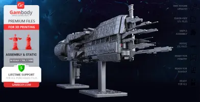
WHAT WILL YOU GET AFTER PURCHASE?
- STL files of USS Sulaco Model for 3D printing which consist of 39 parts;
- 3 versions of files for this model for FFF/FDM and DLP/SLA/SLS printers;
- High-poly detailed model of USS Sulaco;
- Detailed settings that we provide as a recommendation for Cura , Simplify3D and Slic3r for the best print;
- Full technical support from the Gambody Support Team.
You can get the model of USS Sulaco for 3D Printing immediately after the purchase! Just click the green Buy button in the top-right corner of the model’s page. You can pay with PayPal or your credit card.
Watch the tutorial on how to assemble the USS Sulaco 3D Printing Model at Gambody YouTube channel.
Also, you may like other Space Ships 3D Printing Models as well as Alien vs Predator 3D Printing Figurines.
_______
FAQ:
Where can I print a model if I have no printer?
How to get started with 3D printing?
How to set up my 3D printer?
How to choose right 3D model print bed positioning?
How to paint printed figurine?
Average customer rating (14 reviews)
4.2
Ratings breakdown
Click a star rating to filter reviews
Overall experience
Level of detail in the model
4.2
Model cut quality and assembly guide
4.2
Clarity and accuracy of the model page
4.2
Level of detail in the model
5
Model cut quality and assembly guide
0.5
Clarity and accuracy of the model page
1
We hope your upcoming 3D projects bring you nothing but enjoyment!
Part #2 has been reworked and is now divided into four separate components: part #2 and parts #25–27. This change significantly reduces the need for difficult supports and makes orientation and post-processing more manageable. In addition, where technically possible, the internal geometry has been smoothed to further ease printing and support removal.
We continuously strive to maintain a high standard for all Premium models created by contributing artists, and feedback like yours plays an important role in refining both the models and the overall printing experience for the community.
Thank you again for taking the time to share your observations, we truly appreciate it and remain open to further suggestions.
First, concerning part orientation and supports, the orientations shown in the files or manuals are recommendations, not strict requirements. With this specific geometry and segmentation, there is unfortunately no single “perfect” orientation for part #2 that completely avoids supports on all visible surfaces. Different hobbyists prioritize different areas depending on whether they plan to sand, fill, or paint certain sections. Your experience here is valid, but it’s not unique to this model and reflects the inherent complexity of large FDM ship hulls.
As for the way the model is segmented: the cutting standards have evolved since this model was originally created. We acknowledge that modern approaches allow for better optimization, and we plan to improve the segmentation in line with current standards as part of a future update.
Regarding the hollow structure and lighting: the model does not include dedicated wire tunnels. Instead, the interior is intentionally hollow to allow for lighting setups using LEDs or fiber optics and to reduce overall weight without compromising structural strength. While this can make support removal more challenging in some configurations, many hobbyists have successfully printed the model in FDM. In practice, careful support tuning is important. We recommend using tree supports and slightly increasing the Top Z Distance by about 0.2 mm, which helps supports detach more easily while still providing adequate support during printing. Alternatively, supports can be manually blocked in certain internal areas in the slicer. Printing without internal supports may slightly affect the interior surface quality, but it significantly simplifies wire routing for lighting and does not affect the external appearance of the part.
We would also like to clarify the statement that the model was never FDM-printed before. This ship is not new, and there is a large number of completed FDM prints from the community that demonstrate successful results. Here are just a few examples shared by makers:
https://www.facebook.com/groups/183216945475583/posts/2153360245127900/
https://www.facebook.com/groups/183216945475583/posts/1303043216826278/
https://www.facebook.com/groups/183216945475583/posts/1048280342302568/
https://www.facebook.com/groups/183216945475583/posts/1883539838776610/
Your feedback is valuable, and we will absolutely forward it to our team as input for a future upgrade of the model.
The key point we want to emphasize is that while the model is complex and demanding, it is not unprintable in FDM, as proven by many completed builds. At the same time, we acknowledge that it requires experience, tuning, and patience, and it may not align with every maker’s expectations.
Thank you again for sharing your experience. We genuinely appreciate honest criticism, and it helps us continue improving models and support. If you’d like any assistance with your project, please feel free to reach out. We’re here to help.
Level of detail in the model
5
Model cut quality and assembly guide
5
Clarity and accuracy of the model page
5
Level of detail in the model
4
Model cut quality and assembly guide
4
Clarity and accuracy of the model page
4
Level of detail in the model
3
Model cut quality and assembly guide
3
Clarity and accuracy of the model page
3
Level of detail in the model
2
Model cut quality and assembly guide
2
Clarity and accuracy of the model page
2
Level of detail in the model
4
Model cut quality and assembly guide
4
Clarity and accuracy of the model page
4
Level of detail in the model
5
Model cut quality and assembly guide
5
Clarity and accuracy of the model page
5
Level of detail in the model
4
Model cut quality and assembly guide
4
Clarity and accuracy of the model page
4
Level of detail in the model
4
Model cut quality and assembly guide
4
Clarity and accuracy of the model page
4
Level of detail in the model
5
Model cut quality and assembly guide
5
Clarity and accuracy of the model page
5
Level of detail in the model
5
Model cut quality and assembly guide
5
Clarity and accuracy of the model page
5
Level of detail in the model
4
Model cut quality and assembly guide
4
Clarity and accuracy of the model page
4
Level of detail in the model
5
Model cut quality and assembly guide
5
Clarity and accuracy of the model page
5
Level of detail in the model
5
Model cut quality and assembly guide
5
Clarity and accuracy of the model page
5
Below you'll find detailed slicing settings for Bambu Studio 2.0+, Orca Slicer 2.0+, UltiMaker Cura 5.0+, PrusaSlicer 2.0+, Slic3r 1.3+, Simplify3D 5.0+ to help you get the best results when printing this model. These settings are optimized specifically for this 3D model, but please note they may need slight adjustments depending on your printer or filament. When in doubt, refer to your printer's user manual.
To avoid printing issues and achieve the best quality, we highly recommend applying the following settings:
For better quality use 0.12 mm layer height, for fast printing use 0.2 mm layer height. For pins and the Ge connectors, use 0.2 layer height.
120-150% of your Layer Height
But you can paint the seam if you want.
You have to calibrate this parameter
You have to calibrate this parameter
You have to calibrate this parameter
For pins and power elements of the structure, such as the vehicle frame, use 3 loop
Disabled for vehicles and enabled for characters
For 0,2 Layer Height
The parameters in this tab vary greatly, it all depends on the quality of your printer. For example, if you have a classic Ender3, stick to the minimum parameters, but if you have a newer printer, for example Anycubic cobra 3 v2, you can select the maximum recommended values
Settings for advanced users, change these parameters only if you have sufficient 3D printing expertise
Enable this parameter if your model requires supports
We also recommend placing and removing supports manually in some places using special button
1-2 loops for more thick support
Top Z distance = 1-1.3 layer Height. If the supports are hard to remove, try increasing this setting by 0.1-0,4 mm
Bottom Z distance = 1-1.3 layer Height. If the supports are hard to remove, try increasing this setting by 0.1-0,4 mm
You have to calibrate this parameter which one is better for your filament
Increase this parameter if the supports are hard to remove from walls
For PLA and PETG filament types
5-8 mm is optional for small prints that have bad adhesion to the build plate
You have to calibrate this parameter
Read the description on your filament roll
Read the description on your filament roll and increase this parameter for fast printers
Read the description on your filament roll and increase this parameter for fast printers
For better quality use 0.12 mm layer height, for fast printing use 0.2 mm layer height. For pins and the Ge connectors, use 0.2 layer height.
120-150% of your Layer Height
But you can paint the seam if you want.
0.01-0.05 You have to calibrate this parameter
0.01-0.05 You have to calibrate this parameter
0.1-0.2 You have to calibrate this parameter
For pins and power elements of the structure, such as the vehicle frame, use 3 loop
Disabled for vehicles and ships, enabled for characters
For 0,2 Layer Height
For 0,2 Layer Height
The parameters in this tab vary greatly, it all depends on the quality of your printer. For example, if you have a classic Ender3, stick to the minimum parameters, but if you have a newer printer, for example, Anycubic Kobra 3 Or Bambulab A1, you can select the maximum recommended values.
Settings for advanced users, change these parameters only if you have sufficient 3D printing expertise
Enable this parameter if your model requires supports
We also recommend placing and removing supports manually in some places using special button
Top Z distance = 1-1.3 layer Height. If the supports are hard to remove, try increasing this setting by 0.1-0,4 mm
Bottom Z distance = 1-1.3 layer Height. If the supports are hard to remove, try increasing this setting by 0.1-0,4 mm
Increase this parameter if the supports are hard to remove from walls
For PLA and PETG filament types
5-8 mm is optional for small prints that have bad adhesion to the build plate
Read the description on your filament roll
Read the description on your filament roll and increase this parameter for fast printers
You have to calibrate this parameter
Read the description on your filament roll and increase this parameter for fast printers
Read the description on your filament roll
This field is filled in according to your printer specifications when you add it to the slicer.
You can add custom G-code here for the start and end of the print. However, be careful - this is for advanced users only!
You have to calibrate your printer using Ge retraction test models
Retraction Length: For direct-drive setups use 0.5 mm to 2.5 mm; for Bowden extruders use 5 to 7 mm
This is how fast the filament is pulled back—40-60 mm/s for direct drive and 30-50 mm/s for Bowden setups.
You have to calibrate this parameter: Reduce it until the printer starts to hit the parts with the nozzle during printing, then increase it by 0.2.
For better quality use 0.12 mm layer height, for fast printing use 0.2 mm layer height. For pins and the Ge connectors, use 0.2 layer height.
120-150% of your Layer Height
To increase the strength of the print parts, use wall line count: 3
For pins and connectors use 50% Infill
These parameters are for standard PLA plastic. If you are using a different type of plastic, check the printing temperature recommended by the manufacturer. Also, read the description on your filament spool. For fast printers, add +30 °C to the current parameters.
The parameters in this tab vary greatly, it all depends on the quality of your printer. For example, if you have a classic Ender3, stick to the minimum parameters, but if you have a newer printer, for example Anycubic cobra 3 v3, you can select the maximum recommended values
Settings for advanced users, change these parameters only if you have sufficient 3D printing expertise.
You need to calibrate this parameter using Gambody test models. These values are average values for a Direct Drive extruder; for a Bowden extruder, the values should be increased.
You need to calibrate this parameter using Gambody test models. These values are average values for a Direct Drive extruder; for a Bowden extruder, the values should be increased.
Use this value other than 0 if your nozzle catches on the internal infill during travel moves. Try to keep this value as low as possible in height.
Use normal supports to support large, straight surfaces (most mechanical or technical parts).
You have to calibrate this parameter according to the capabilities of your printer and your filament, using a Gambody test models.
Use 1 instead of 0 if your supports are thin and tall. They will be harder to remove, but much stronger.
Top Z distance = 1-1.3 layer Height. If the supports are hard to remove, try increasing this setting by 0.1-0,4 mm
Increase this parameter if the supports are hard to remove from walls
Use tree supports to support complex objects, such as characters.
You have to calibrate this parameter according to the capabilities of your printer and your filament, using a Gambody test models.
Top Z distance = 1-1.3 layer Height. If the supports are hard to remove, try increasing this setting by 0.1-0,4 mm
Increase this parameter if the supports are hard to remove from walls
Use a skirt for all parts when printing on outdated printers.
Use a brim when printing thin but tall parts, as well as parts with a small bed adhesion area.
For better quality use 0.12 mm layer height, for fast printing use 0.2 mm layer height. For pins and the Ge connectors, use 0.2 layer height.
120-150% of your Layer Height
for 0.2 Layer Height
But you can paint the seam if you want.
(for PLA and PETG)
(5-8 mm is optional for small prints that have bad adhesion to the build plate)
Enable this parameter if your model requires supports
(45-50 degree)You have to calibrate this parameter according to the capabilities of your printer
and your filament, using a Gambody test models.
Top contact Z distance = 1-1.3 layer Height. If the supports are hard to remove, try
increasing this setting by 0.1-0,4 mm
Top contact Z distance = 1-1.3 layer Height. If the supports are hard to remove, try
increasing this setting by 0.1-0,4 mm
Increase this parameter if the supports are hard to remove from walls
The parameters in this tab vary greatly, it all depends on the quality of your printer. For example, if you have a classic Ender3, stick to the minimum parameters, but if you have a newer printer, for example Anycubic cobra 3 v3, you can select the maximum recommended values
Settings for advanced users, change these parameters only if you have sufficient 3D printing expertise. Use the minimum value for outdated printers without acceleration calibration, and the maximum value for modern printers if you need it.
These settings only work for 3D printers with multiple extruders
You can try setting all parameters in this section, except the First layer, to values between 0.75% of your nozzle diameter and 1.25% of your nozzle diameter. Adjusting them will help you work out the optimal parameters for the best quality for your print. As for the First layer, you can set it to 150% of the diameter of your nozzle for better adhesion to the build plate (for a nozzle with a diameter of 0.4 mm, the First layer extrusion width can be from 0.3 mm to 0.5 mm)
For better printing quality you have to calibrate this parameter using Gambody test model.
Check your filament manufacturer's temperature recommendations on the spool.
Cooling parameters depends on the material you use for printing.
*for PLA
For better quality use 0.12 mm layer height, for fast printing use 0.2 mm layer height. For pins and the Ge connectors, use 0.2 layer height.
120-150% of your Layer Height
For 0.12 Layer Height
For 0.12 Layer Height
For pins and connectors use 50% Infill
Use skirt for outdated 3d printers
(5-8 mm is optional for small prints that have bad adhesion to the build plate)
Enable this parameter if your model requires supports
(45-60 degree)You have to calibrate this parameter according to the capabilities of your printer and your filament, using a Gambody test models
Contact Z distance = 1-1.3 layer Height. If the supports are hard to remove, try increasing this setting by 0.1-0,4 mm
The parameters in this tab vary greatly, it all depends on the quality of your printer. For example, if you have a classic Ender3, stick to the minimum parameters, but if you have a newer printer, for example Anycubic cobra 3 v3, you can select the maximum recommended values
Settings for advanced users, change these parameters only if you have sufficient 3D printing expertise. Use the minimum value for outdated printers without acceleration calibration, and the maximum value for modern printers if you need it.
You have to calibrate this parameter from 0.9 to 1.1 according to the capabilities of your printer and your filament, using a Gambody test models.
Check your filament manufacturer's temperature recommendations on the spool.
Cooling parameters depends on the material you use for printing.
Calibrate this value if you need to reduce or improve the adhesion between the plastic and the heat bed
Your current nozzle diameter
You need to calibrate this parameter using Gambody test models. These values are average values for a Direct Drive extruder; for a Bowden extruder, the values should be increased.
Your current nozzle diameter
You have to calibrate this parameter using Gambody test models.
You need to calibrate this parameter using Gambody test models. These values are average values for a Direct Drive extruder; for a Bowden extruder, the values should be increased.
For better quality use 0.12 mm layer height, for fast printing use 0.2 mm layer height. For pins and the Ge connectors, use 0.2 layer height.
For 0,2 Layer Height
For 0,2 Layer Height
To increase the strength of the print parts, use Outline Perimeters: 3
You can enable this parameter to print rounded or spherical models, as well as character models.
Use this option only if your parts are too tight. but better calibrate your printer extrusion
Use this option only if your parts are too tight. but better calibrate your printer extrusion
Use 2 and more if you want to create skirt instead brim
1-2 for skirt and 10-20 for brim
Use for wipe nozzle if you need
Use For ABS filament
For pins and connectors use 50% Infill
Top Z distance = 1-1.3 layer Height. If the supports are hard to remove, try increasing this setting by 0.1-0,4 mm
Calibrate your filament and detect optimal temperature for it
Average temperature for PLA filament
The parameters in this tab vary greatly, it all depends on the quality of your printer. For example, if you have a classic Ender3, stick to the minimum parameters, but if you have a newer printer, for example Anycubic cobra 3 v3, you can select the maximum recommended values
Settings for advanced users, change these parameters only if you have sufficient 3D printing expertise.